1
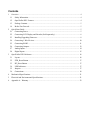
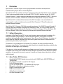
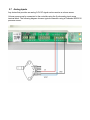
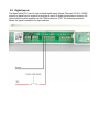
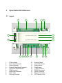
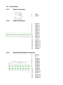
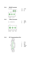
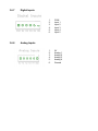
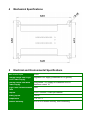
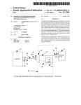
OpenTroller DX1 User Manual Document Revision 1.0 July 2, 2012 © 2012 Open Source Control Systems, Inc. All Rights Reserved. Product warranty or service will not be extended if: (1) the product is repaired, modified or altered, unless such repair, modification of alteration is authorized in writing by Open Source Control Systems, Inc. (“OSCSYS”); or (2) the serial number of the product is defaced or missing. OSCSYS PROVIDES THIS MANUAL “AS IS” WITHOUT WARRANTY OF ANY KIND AND MAKES NO OTHER REPRESENTATIONS OR WARRANTIES EITHER EXPRESS OR IMPLIED AS TO FITNESS FOR PURPOSE, MERCHANTABILITY OR OTHERWISE IN RESPECT OF THE PRODUCT. IN NO EVENT SHALL OSCSYS, ITS DIRECTORS, OFFICERS, EMPLOYEES OR AGENTS BE LIABLE FOR ANY DIRECT, INDIRECT, SPECIAL, INCIDENTAL, OR CONSEQUENTIAL DAMAGES (INCLUDING DAMAGES FOR LOSS OF PROFITS, LOSS OF BUSINESS, LOSS OF USE OR DATA, INTERRUPTION OF BUSINESS AND THE LIKE) WHETHER SUCH DAMAGES ARE INCURRED BY THE PERSON TO WHOM THIS WARRANTY EXTENDS OR A THIRD PARTY, EVEN IF OSCSYS HAS BEEN ADVISED OF THE POSSIBILITY OF SUCH DAMAGES ARISING FROM ANY DEFECT OR ERROR IN THIS MANUAL OR PRODUCT. SPECIFICATIONS AND INFORMATION CONTAINED IN THIS MANUAL ARE FURNISHED FOR INFORMATIONAL USE ONLY, AND ARE SUBJECT TO CHANGE AT ANY TIME WITHOUT NOTICE, AND SHOULD NOT BE CONSTRUED AS A COMMITMENT BY OSCSYS. OSCSYS ASSUMES NO RESPONSIBILITY OR LIABILITY FOR ANY ERRORS OR INACCURACIES THAT MAY APPEAR IN THIS MANUAL, INCLUDING THE PRODUCTS AND SOFTWARE DESCRIBED IN IT. Products and corporate names appearing in this manual may or may not be registered trademarks or copyrights of their respective companies, and are used only for identification or explanation and to the owners’ benefit, without intent to infringe. Contents 1 2 3 Overview ........................................................................................................................................... 4 1.1 Safety Information ...................................................................................................................... 4 1.2 OpenTroller DX1 Features ......................................................................................................... 4 1.3 Package Contents ....................................................................................................................... 5 1.4 Before You Proceed .................................................................................................................... 5 Quick Start Guide .............................................................................................................................. 5 2.1 Connecting Power ...................................................................................................................... 5 2.2 Connecting LCD Display and Encoder (Sold separately) .......................................................... 6 2.3 Installing/Upgrading Firmware .................................................................................................. 8 2.4 Connecting 1-Wire Devices ..................................................................................................... 10 2.5 Connecting RS485.....................................................................................................................11 2.6 Connecting Outputs .................................................................................................................. 12 2.7 Analog Inputs ........................................................................................................................... 14 2.8 Digital Inputs ............................................................................................................................ 15 OpenTroller DX1 Reference ............................................................................................................ 16 3.1 Layout ....................................................................................................................................... 16 3.2 ETH_Reset Button ................................................................................................................... 17 3.3 BT_Reset Button ...................................................................................................................... 17 3.4 LED Indicators ......................................................................................................................... 17 3.5 Jumpers ..................................................................................................................................... 17 3.6 Connections .............................................................................................................................. 18 4 Mechanical Specifications ............................................................................................................... 21 5 Electrical and Environmental Specifications ................................................................................... 21 6 Appendix A – Warranty ................................................................................................................... 22 1 Overview OpenTroller is a series of open source, programmable controllers developed and manufactured by Open Source Control Systems: OpenTroller BX1: The smallest and least expensive model in the OpenTroller series. The BX1 is sold as an assembled printed circuit board (PCB). The BX1 features include: 6x 12VDC Sourced Outputs (1 output supporting hardware controlled high-frequency PWM), 1-Wire bus interface, I2C bus interface, RS-485 bus interface and USB (virtual serial port) interface. OpenTroller EX1: Includes all the features of the BX1 but ships as an assembled unit complete with a wall-mountable enclosure with 20x4 Character LCD and Encoder and optional Ethernet interface. OpenTroller DX1: Features: DIN Rail mountable enclosure, 14x 12VDC Sourced Outputs (6 outputs supporting hardware controlled high frequency PWM), 4x 5VDC Analog Inputs, 5x 12VDC Digital Inputs + Dedicated E-Stop Input, 1-Wire bus interface, I2C bus interface, RS485 bus interface, USB (virtual serial port) interface and optional Ethernet interface. 1.1 Safety Information Integration of the OpenTroller DX1 into a control system requires electrical knowledge. It is solely the installer’s responsibility to assure that the system is configured in a manner consistent with applicable safety requirements. Open Source Control Systems, Inc. does not control how this board is integrated into the control system and cannot be responsible for guaranteeing the safety of your system. This device is not guaranteed to be fail-safe. For example, the microcontroller could fail leaving an output active. The system into which the device is installed should provide fail-safe protection and emergency stop capability. If the device is to be used with dangerous voltages care must be taken to prevent an operator or installer from coming into contact with these voltages. An enclosure that allows for modest ventilation, but prevents intrusion by operator’s hands and foreign objects should be utilized with this board. 1.2 OpenTroller DX1 Features • • • • • • • • • Atmel 8-bit AVR RISC-based microcontroller with 128KB flash, 4KB EEPROM and 16KB SRAM (14) Transistor based sourced 12V DC Outputs (4) 5V DC Analog Inputs (5) 12V DC Digital Inputs + (1) Dedicated E-Stop Input I2C port for connection to expansion modules RS485 Communications port USB Communications port 1-Wire Communications port DIN Rail Mountable Case 1.3 Package Contents OpenTroller DX1 Device • 1.4 Before You Proceed Please review all safety and connection information before attempting to connect and power on your OpenTroller DX1. Open Source Control Systems, Inc. is not responsible for damage caused to boards by improper connections. If you have any questions please do not hesitate to contact support. You can find phone numbers and contact forms on our website (http://www.oscsys.com). 2 Quick Start Guide 2.1 Connecting Power Power is supplied to the OpenTroller DX1 via the power connection JP2 The OpenTroller DX1 requires a 12V DC power supply of at least 500mA. Additional devices such as relay boards will increase the power supply requirements. A 3A or greater power supply is recommended to ensure external device support. It is recommended to measure the power supply output with a voltmeter prior to connecting it to the OpenTroller DX1. Damage caused by connecting the OpenTroller DX1 to improper power supply voltages will not be covered under warranty. WARNING: NEVER CONNECT OPENTROLLER DX1 TO AC POWER OR DC POWER SUPPLIES GREATER THAN 12VDC. 2.2 Connecting LCD Display and Encoder (Sold separately) The OpenTroller DX1 can be connected to a 20x4 character LCD and Encoder via the OpenTroller Display Module connected to the I2C port: Connect the 5 pin polarized, locking I2C cable into the OpenTroller's I2C Port (Connector X4). Connect the other end to the I2C port on the display module. Connect the encoder to the encoder port of the display module and then connect the display module to the LCD using the 16-pin connector. Refer to the following examples: 2.3 Installing/Upgrading Firmware Multiple firmware solutions are available for the OpenTroller platform to support specific applications. The latest stable release is always recommended for production systems however the following list identifies the minimum versions required to support the OpenTroller DX1: BrewTroller 2.5 Build 917 FermTroller TBD 2.3.1 Connect to PC A mini-B USB cable is required to connect the OpenTroller DX1 board to your PC/Mac for firmware upgrading. The OpenTroller DX1 uses a FTDI FT232RL module that installs as a Virtual COM Port (VCP) device. Drivers are usually available within current versions of available Operating Systems. If necessary you may download drivers form the FTDI website (http://www.ftdichip.com). 2.3.2 Download Required Files Arduino Integrated Development Environment (IDE) – A custom version of the Arduino IDE is required to support the OpenTroller DX1 to provide support for the ATMEGA1284P microcontroller and external libraries used by the firmware. The customized IDE is available under the ‘Downloads’ section of the BrewTroller website (http://www.brewtroller.com). Extract the ZIP file to a location on your hard drive. Firmware Source – The firmware source code for your target application (ie BrewTroller or FermTroller) is available under the ‘Downloads’ section of the BrewTroller website (http://www.brewtroller.com). There are often multiple versions of each firmware application available for download: o Stable – This is the current version recommended for production systems. Start with this release for a new system. o Testing – This is a feature-frozen release of the development firmware that is in the process of moving to stable. Often users are encouraged to download and test this release to help identify any bugs prior to the release being moved to ‘Stable’. It is important to start with ‘Stable’ first to ensure your system is working properly before installing a ‘Testing’ release. o Development (Trunk) – This is the current release still under development. It is recommended for developers only. Extract the ZIP to a location on your hard drive. 2.3.3 Select Hardware Profile Note: The following provides generic instructions not specific to either FermTroller or BrewTroller firmware. Your firmware download may contain multiple hardware profiles for the OpenTroller DX1. Refer to the specific firmware documentation for more details regarding selecting a hardware profile. In the HWProfiles folder of the firmware source open the ‘OpenTroller DX1’ subfolder and copy the HWProfile.h file to the root folder of the firmware source (ie ‘FermTroller’ or ‘BrewTroller’ depending on the firmware used). You will replace the HWProfile.h included in the root folder of the firmware source. 2.3.4 Configure and Upload Note: The following provides generic instructions not specific to either FermTroller or BrewTroller firmware. Refer to the specific firmware documentation for more details regarding available compile options. Launch the Arduino executable from the Arduino IDE folder extracted previously Select ‘Open’ from the ‘File’ menu, browse to the folder where you extracted the firmware source and open the BrewTroller.pde or FermTroller.pde as appropriate. Select the ‘Sanguino w/ ATMEGA1284P’ from the ‘Board’ menu under ‘Tools’. Select the serial port for the device from the ‘Serial Port’ menu under ‘Tools’. Review the Config.h tab for compile options if necessary (refer to firmware documentation) Select ‘Upload to I/O Board’ from the ‘File’ menu. 2.4 Connecting 1-Wire Devices The OpenTroller provides a 1-Wire device bus to interface to temperature sensors and other IO devices. The 1-Wire network uses a single shared data line to communicate with many devices. Each 1-Wire device has a unique 48-bit address that is used to when sending and receiving data to individual network nodes. The JP4 connector provides access to the 1-Wire bus. A constant 5VDC (VCC) connection is provided in addition to the data and ground pins. The recommended topology for 1-Wire networks is a bus. A single cable should connect from the OpenTroller to the first device with the smallest length stub for each device (<1m). The second deviceis connected via a cable from the first device and so on. Open Source Control Systems sells a series of M12 cables and splitters that are perfect for connecting 1-Wire networks. For more information, visit www.oscsys.com. 2.5 Connecting RS485 The OpenTroller provides an RS485 serial bus to interface with other IO devices. RS485 uses a differential pair of lines (A and B) for communication. Connect the COM, A and B terminals to the same terminals on the external IO board. When connecting more than two devices a daisy chain or bus topology is recommended as illustrated below: 2.6 Connecting Outputs The outputs on the OpenTroller DX1 provide up to 100mA @ 12V per channel. Important: The OpenTroller DX1 does not provide any back EMF protection when used with standard mechanical relays. You must install a reverse protection diode onto the relay coil terminals to prevent noise and potential damage to the OpenTroller DX1. 2.6.1 Solid State Relay Example To connect devices such as a solid state relay refer to the diagram below. Connect the OpenTroller output to the positive input terminal of the SSR. Connect the negative input terminal of the SSR to your power supply ground. 2.6.2 2 Way Motorized Ball Valve Example 2.7 Analog Inputs Any device that provides an analog 0-5V DC signal can be used as a volume sensor. Volume sensors can be connected to the controller using the 6 pole analog input screw terminal block. The following diagram shows a typical connection using a Freescale MPX5010 pressure sensor: 2.8 Digital Inputs The OpenTroller DX1 has five opto-isolated digital inputs (Screw Terminals JP10). A 12VDC signal to a digital input is required to activate an input. All digital inputs share a common DC ground which must be supplied via the COM terminal on JP10. The following schematic shows the typical connection for input switches. 3 OpenTroller DX1 Reference 3.1 Layout 2 3 4 6 5 1 7 8 18 9 17 1. 2. 3. 4. 5. 6. 7. 8. 9. 16 15 14 E-Stop Header Power Input Terminals Output Terminals External Relay Board Connector Auto Reset Enable/Disable USB Connector OpenTroller Heartbeat Power Light Ethernet Heartbeat 13 10. 11. 12. 13. 14. 15. 16. 17. 18. 12 11 10 Ethernet Reset OpenTroller Reset Analog Inputs Digital Inputs 1-Wire Connector RS485 Termination RS485 Connector Ethernet Connector I2C Expansion Port 3.2 ETH_Reset Button Used to restart the embedded Ethernet module. 3.3 BT_Reset Button Used to restart (reboot) the firmware. 3.4 LED Indicators 3.4.1 Power Indicates power is connected to controller. 3.4.2 OpenTroller Heatbeat Indicates proper operation of the controllers firmware. The heartbeat indicator should toggle on/off every 750ms. 3.4.3 Ethernet Heartbeat Indicates proper operation of embedded Ethernet module. 3.5 Jumpers 3.5.1 Auto-Reset Allows automatic reset of board via serial port DTR for uploading firmware during microcontroller boot process. May be disconnected to avoid resets caused by serial port activation when not uploading firmware. 3.5.2 RS485 Termination This jumper needs to be connected if the OpenTroller DX1 is the first or last device on the RS485 bus. 3.6 Connections 3.6.1 3.6.2 3.6.3 Power Connector 1. 2. GND 12VDC 1. 2. 3. 4. 5. 6. 7. 8. 9. 10. 11. 12. 13. 14. 15. 16. 17. 18. Ground Output 1 Output 2 Output 3 Output 4 Output 5 Ground Output 6 Output 7 Output 8 Output 9 Ground Output 10 Output 11 Output 12 Output 13 Output 14 Ground Output Terminals External Relay Board Connector 1. 2. 3. 4. 5. 6. 7. 8. 9. 10. 11. 12. 13. 14. 15. 16. Ground 12V Output 1 Output 2 Output 3 Output 4 Output 5 Output 6 Output 7 Output 8 Output 9 Output 10 Output 11 Output 12 Output 13 Output 14 3.6.4 3.6.5 3.6.6 RS485 Terminals 17. 18. 19. COM A B 1. 2. 3. GND 1Wire 5V 1. 2. 3. 4. 5. SDA SCL N/C 12VDC GND 1-Wire Connector I2C Communications Port 3.6.7 3.6.8 Digital Inputs 1. 2. 3. 4. 5. 6. COM Input 1 Input 2 Input 3 Input 4 Input 5 1. 2. 3. 4. 5. 6. 5V Analog 1 Analog 2 Analog 3 Analog 4 Ground Analog Inputs 4 Mechanical Specifications 5 Electrical and Environmental Specifications Main Power Input 12VDC External Loads from Logic Level Power Supply Regulated +5V supply (referenced to PC ground) External Loads from Main Power Supply Unregulated +12V supply on connector I2CLCD Maximum current 1A Logic-Level Communication 5VDC Ports Outputs 12VDC Sourced, 150mA per channel Analog Inputs 0-5VDC Temperature 0° to +55° C Relative Humidity 20% to 80% relative humidity, non-condensing 6 Appendix A – Warranty Open Source Control Systems, Inc. (OSCSYS) warrants that this hardware product is in good working condition, according to its specifications at the time of shipment, for a period of 90 days from the date it was shipped from OSCSYS. Should the product, in OSCSYS's opinion, malfunction within the warranty period, OSCSYS will repair or replace the product without charge. Any replaced parts become the property of OSCSYS. This warranty does not apply to the software component of a product or to a product which has been damaged due to accident, misuse, abuse, improper installation, usage not in accordance with product specifications and instructions, natural or personal disaster or unauthorized alterations, repairs or modifications. All warranties for this product, expressed or implied, are limited to 90 days from the date of purchase and no warranties, expressed or implied, will apply after that period. All warranties for this product, expressed or implied, shall extend only to the original purchaser. The liability of Open Source Control Systems, Inc. in respect of any defective product will be limited to the repair or replacement of such product. Open Source Control Systems, Inc. may use new or equivalent to new replacement parts. Open Source Control Systems, Inc. makes no other representations or warranties as to fitness for purpose, merchantability or otherwise in respect of the product. No other representations, warranties or conditions, shall be implied by statute or otherwise. In no event shall Open Source Control Systems, Inc. be responsible or liable for any damages arising (a) from the use of the product; (b) from the loss of use of the product; (c) from the loss of revenue or profit resulting from the use of the product; or (d) as a result of any event, circumstance, action or abuse beyond the control of Open Source Control Systems, Inc. whether such damages be direct, indirect, consequential, special or otherwise and whether such damages are incurred by the person to whom this warranty extends or a third party.