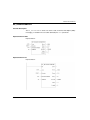
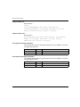
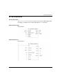
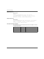
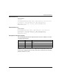
1
Unity Pro
35010605 07/2011
Unity Pro
Motion Function Blocks
Block Library
35010605.07
07/2011
www.schneider-electric.com
The information provided in this documentation contains general descriptions and/or
technical characteristics of the performance of the products contained herein. This
documentation is not intended as a substitute for and is not to be used for
determining suitability or reliability of these products for specific user applications. It
is the duty of any such user or integrator to perform the appropriate and complete
risk analysis, evaluation and testing of the products with respect to the relevant
specific application or use thereof. Neither Schneider Electric nor any of its affiliates
or subsidiaries shall be responsible or liable for misuse of the information contained
herein. If you have any suggestions for improvements or amendments or have found
errors in this publication, please notify us.
No part of this document may be reproduced in any form or by any means, electronic
or mechanical, including photocopying, without express written permission of
Schneider Electric.
All pertinent state, regional, and local safety regulations must be observed when
installing and using this product. For reasons of safety and to help ensure
compliance with documented system data, only the manufacturer should perform
repairs to components.
When devices are used for applications with technical safety requirements, the
relevant instructions must be followed.
Failure to use Schneider Electric software or approved software with our hardware
products may result in injury, harm, or improper operating results.
Failure to observe this information can result in injury or equipment damage.
© 2011 Schneider Electric. All rights reserved.
2
35010605 07/2011
Document Set
Related Documents
Related Documentation:
z Unity Pro Online Help
z Unity Pro Online Help (MFBs using Unity Pro, Start-Up Guide)
z Lexium 05 Documentation CD delivered with the product
z Lexium 15 Documentation CD delivered with the product
z ATV 31 User Manual
z ATV 32 User Manual
z ICLA, IFxx User Manual
z ATV 71 User Manual
z Unilink L for Lexium 15LP and Unilink MH for Lexium 15MP/HP Online Help
z Lexium 32 documentation
35010605 07/2011
3
4
35010605 07/2011
Table of Contents
Safety Information . . . . . . . . . . . . . . . . . . . . . . . . . . . . . .
About the Book . . . . . . . . . . . . . . . . . . . . . . . . . . . . . . . . .
Part I General . . . . . . . . . . . . . . . . . . . . . . . . . . . . . . . . . . . .
Chapter 1 Block Types and their Applications . . . . . . . . . . . . . . . .
Block Types. . . . . . . . . . . . . . . . . . . . . . . . . . . . . . . . . . . . . . . . . . . . . . . .
FFB Structure . . . . . . . . . . . . . . . . . . . . . . . . . . . . . . . . . . . . . . . . . . . . . .
EN and ENO . . . . . . . . . . . . . . . . . . . . . . . . . . . . . . . . . . . . . . . . . . . . . . .
Chapter 2 Availability of the blocks on the various hardware
platforms . . . . . . . . . . . . . . . . . . . . . . . . . . . . . . . . . . . . . .
7
9
11
13
14
16
19
23
Availability of Blocks on the Various Servodrives . . . . . . . . . . . . . . . . . . .
23
Part II MFB blocks . . . . . . . . . . . . . . . . . . . . . . . . . . . . . . . .
27
Chapter 3 The RefAxis parameter. . . . . . . . . . . . . . . . . . . . . . . . . . .
The Axis_Ref. . . . . . . . . . . . . . . . . . . . . . . . . . . . . . . . . . . . . . . . . . . . . . .
The status chart of the axis . . . . . . . . . . . . . . . . . . . . . . . . . . . . . . . . . . . .
Chapter 4 Motion Function Block . . . . . . . . . . . . . . . . . . . . . . . . . . .
MFB blocks and basic parameters . . . . . . . . . . . . . . . . . . . . . . . . . . . . . .
CAN_HANDLER . . . . . . . . . . . . . . . . . . . . . . . . . . . . . . . . . . . . . . . . . . . .
MC_READPARAMETER . . . . . . . . . . . . . . . . . . . . . . . . . . . . . . . . . . . . .
MC_WRITEPARAMETER. . . . . . . . . . . . . . . . . . . . . . . . . . . . . . . . . . . . .
MC_READACTUALPOSITION . . . . . . . . . . . . . . . . . . . . . . . . . . . . . . . . .
MC_READACTUALVELOCITY. . . . . . . . . . . . . . . . . . . . . . . . . . . . . . . . .
MC_READACTUALTORQUE . . . . . . . . . . . . . . . . . . . . . . . . . . . . . . . . . .
MC_TORQUECONTROL . . . . . . . . . . . . . . . . . . . . . . . . . . . . . . . . . . . . .
MC_RESET. . . . . . . . . . . . . . . . . . . . . . . . . . . . . . . . . . . . . . . . . . . . . . . .
MC_STOP . . . . . . . . . . . . . . . . . . . . . . . . . . . . . . . . . . . . . . . . . . . . . . . . .
MC_POWER . . . . . . . . . . . . . . . . . . . . . . . . . . . . . . . . . . . . . . . . . . . . . . .
MC_MOVEABSOLUTE . . . . . . . . . . . . . . . . . . . . . . . . . . . . . . . . . . . . . . .
MC_MOVERELATIVE. . . . . . . . . . . . . . . . . . . . . . . . . . . . . . . . . . . . . . . .
MC_MOVEADDITIVE . . . . . . . . . . . . . . . . . . . . . . . . . . . . . . . . . . . . . . . .
MC_MOVEVELOCITY . . . . . . . . . . . . . . . . . . . . . . . . . . . . . . . . . . . . . . .
MC_JOG . . . . . . . . . . . . . . . . . . . . . . . . . . . . . . . . . . . . . . . . . . . . . . . . . .
MC_READAXISERROR . . . . . . . . . . . . . . . . . . . . . . . . . . . . . . . . . . . . . .
35010605 07/2011
29
30
31
33
35
39
41
43
45
47
49
51
53
54
56
58
60
62
65
67
71
5
6
MC_READSTATUS . . . . . . . . . . . . . . . . . . . . . . . . . . . . . . . . . . . . . . . . .
MC_HOME. . . . . . . . . . . . . . . . . . . . . . . . . . . . . . . . . . . . . . . . . . . . . . . .
LXM_GEARPOS . . . . . . . . . . . . . . . . . . . . . . . . . . . . . . . . . . . . . . . . . . .
LXM_GearPosS . . . . . . . . . . . . . . . . . . . . . . . . . . . . . . . . . . . . . . . . . . . .
TE_UPLOADDRIVEPARAM . . . . . . . . . . . . . . . . . . . . . . . . . . . . . . . . . .
TE_DOWNLOADDRIVEPARAM . . . . . . . . . . . . . . . . . . . . . . . . . . . . . . .
LXM_UPLOADMTASK . . . . . . . . . . . . . . . . . . . . . . . . . . . . . . . . . . . . . .
LXM_DOWNLOADMTASK . . . . . . . . . . . . . . . . . . . . . . . . . . . . . . . . . . .
LXM_STARTMTASK . . . . . . . . . . . . . . . . . . . . . . . . . . . . . . . . . . . . . . . .
Units and Servodrives . . . . . . . . . . . . . . . . . . . . . . . . . . . . . . . . . . . . . . .
Messaging Service. . . . . . . . . . . . . . . . . . . . . . . . . . . . . . . . . . . . . . . . . .
Memory size. . . . . . . . . . . . . . . . . . . . . . . . . . . . . . . . . . . . . . . . . . . . . . .
75
78
80
83
86
88
90
92
94
96
98
100
Appendices . . . . . . . . . . . . . . . . . . . . . . . . . . . . . . . . . . . . . . . . . . .
103
Appendix A Error Codes and Values . . . . . . . . . . . . . . . . . . . . . . . . . .
105
Tables of Error Codes for the Motion Function Block Library . . . . . . . . .
105
Appendix B MFB performances . . . . . . . . . . . . . . . . . . . . . . . . . . . . . .
109
MFB Performance Table . . . . . . . . . . . . . . . . . . . . . . . . . . . . . . . . . . . . .
109
Glossary . . . . . . . . . . . . . . . . . . . . . . . . . . . . . . . . . . . . . . . . . . .
Index . . . . . . . . . . . . . . . . . . . . . . . . . . . . . . . . . . . . . . . . . . .
113
133
35010605 07/2011
Safety Information
§
Important Information
NOTICE
Read these instructions carefully, and look at the equipment to become familiar with
the device before trying to install, operate, or maintain it. The following special
messages may appear throughout this documentation or on the equipment to warn
of potential hazards or to call attention to information that clarifies or simplifies a
procedure.
35010605 07/2011
7
PLEASE NOTE
Electrical equipment should be installed, operated, serviced, and maintained only by
qualified personnel. No responsibility is assumed by Schneider Electric for any
consequences arising out of the use of this material.
A qualified person is one who has skills and knowledge related to the construction
and operation of electrical equipment and its installation, and has received safety
training to recognize and avoid the hazards involved.
8
35010605 07/2011
About the Book
At a Glance
Document Scope
This manual presents the Motion Function Block (MFB) library using Unity Pro.
Validity Note
This documentation is valid from Unity Pro v6.0.
Product Related Information
WARNING
UNINTENDED EQUIPMENT OPERATION
The application of this product requires expertise in the design and programming
of control systems. Only persons with such expertise should be allowed to
program, install, alter, and apply this product.
Follow all local and national safety codes and standards.
Failure to follow these instructions can result in death, serious injury, or
equipment damage.
User Comments
We welcome your comments about this document. You can reach us by e-mail at
[email protected].
35010605 07/2011
9
10
35010605 07/2011
Unity Pro
General
35010605 07/2011
General
I
Overview
This section contains general information about the Motion Function Blocks (MFB).
What’s in this Part?
This part contains the following chapters:
Chapter
35010605 07/2011
Chapter Name
Page
1
Block Types and their Applications
13
2
Availability of the blocks on the various hardware platforms
23
11
General
12
35010605 07/2011
Unity Pro
Block Types and their Applications
35010605 07/2011
Block Types and their
Applications
1
Overview
This chapter describes the different block types and their applications.
What’s in this Chapter?
This chapter contains the following topics:
Topic
35010605 07/2011
Page
Block Types
14
FFB Structure
16
EN and ENO
19
13
Block Types and their Applications
Block Types
Block Types
Different block types are used in Unity Pro. The general term for the block types is
FFB.
There are the following types of block:
Elementary Function (EF)
z Elementary Function Block (EFB)
z Derived Function Block (DFB)
z Procedure
z
NOTE: Motion Function Blocks are not available on the Quantum platform.
Elementary Function
CAUTION
UNEXPECTED BEHAVIOR OF EQUIPMENT
Do not use links to connect function blocks outputs, when your application relies
on persistent output data of an EF.
Failure to follow these instructions can result in injury or equipment damage.
Elementary functions (EF) have no internal status and one output only. If the input
values are the same, the output value is the same for the executions of the function,
e.g. the addition of two values gives the same result at every execution.
An elementary function is represented in the graphical languages (FBD and LD) as
a block frame with inputs and an output. The inputs are represented on the left and
the outputs on the right of the frame. The name of the function, i.e. the function type,
is shown in the center of the frame.
The number of inputs can be increased with some elementary functions.
NOTE: The deactivation of an EF (EN=0) causes links connected to its Input/Output
to be reset. To transfer the state of the signal do not use a link. A variable must be
connected to the EF’s output and must be used to connect the input of the element.
14
35010605 07/2011
Block Types and their Applications
Elementary Function Block
Elementary function blocks (EFB) have an internal status. If the inputs have the
same values, the value on the outputs can have another value during the individual
executions. For example, with a counter, the value on the output is incremented.
An elementary function block is represented in the graphical languages (FBD and
LD) as a block frame with inputs and outputs. The inputs are represented on the left
and the outputs on the right of the frame. The name of the function block, i.e. the
function block type, is shown in the center of the frame. The instance name is
displayed above the frame.
Derived Function Block
Derived function blocks (DFBs) have the same properties as elementary function
blocks. They are created by the user in the programming languages FBD, LD, IL
and/or ST.
Procedure
Procedures are functions with several outputs. They have no internal state.
The only difference from elementary functions is that procedures can have more
than one output and they support variables of the VAR_IN_OUT data type.
Procedures do not return a value.
Procedures are a supplement to IEC 61131-3 and must be enabled explicitly.
There is no visual difference between procedures and elementary functions.
35010605 07/2011
15
Block Types and their Applications
FFB Structure
Structure
Each FFB is made up of an operation (name of the FFB), the operands are required
for the operation (formal and actual parameters) and an instance name for
elementary/derived function blocks.
Call of a function block in the FBD programming language:
CAUTION
UNEXPECTED APPLICATION BEHAVIOR
Do not call several times the same block instance within a PLC cycle
Failure to follow these instructions can result in injury or equipment damage.
Formal call of a function block in the ST programming language:
16
35010605 07/2011
Block Types and their Applications
Operation
The operation determines which function is to be executed with the FFB, e.g. shift
register, conversion operations.
Operand
The operand specifies what the operation is to be executed with. With FFBs, this
consists of formal and actual parameters.
Formal/actual parameters
Inputs and outputs are required to transfer values to or from an FFB. These are
called formal parameters.
Objects are linked to formal parameters; these objects contain the current process
states. They are called actual parameters.
At program runtime, the values from the process are transferred to the FFB via the
actual parameters and then output again after processing.
The data type of the actual parameters must match the data type of the input/output
(formal parameters). The only exceptions are generic inputs/outputs whose data
type is determined by the actual parameter. If the actual parameters consist of
literals, a suitable data type is selected for the function block.
FFB Call in IL/ST
In text languages IL and ST, FFBs can be called in formal and in informal form.
Details can be found in the Reference manual.
Example of a formal function call:
out:=LIMIT (MN:=0, IN:=var1, MX:=5);
Example of an informal function call:
out:=LIMIT (0, var1, 5);
NOTE: The use of EN and ENO is only possible for formal calls.
VAR_IN_OUT variable
FFBs are often used to read a variable at an input (input variables), to process it and
to output the altered values of the same variable (output variables).
This special type of input/output variable is also called a VAR_IN_OUT variable.
The input and output variable are linked in the graphic languages (FBD and LD)
using a line showing that they belong together.
35010605 07/2011
17
Block Types and their Applications
Function block with VAR_IN_OUT variable in FBD:
Function block with VAR_IN_OUT variable in ST:
MY_EXAMP1 (IN1:=Input1, IN2:=Input2, IO1:=Comb_IN_OUT,
OUT1=>Output1, OUT2=>Output2);
The following points must be considered when using FFBs with VAR_IN_OUT
variables:
z The VAR_IN_OUT inputs must be assigned a variable.
z Literals or constants cannot be assigned to VAR_IN_OUT inputs/outputs.
The following additional limitations apply to the graphic languages (FBD and LD):
When using graphic connections, VAR_IN_OUT outputs can only be connected
with VAR_IN_OUT inputs.
z Only one graphical link can be connected to a VAR_IN_OUT input/output.
z Different variables/variable components can be connected to the VAR_IN_OUT
input and the VAR_IN_OUT output. In this case the value of the variables/variable
component on the input is copied to the output variables/variable component.
z No negations can be used on VAR_IN_OUT inputs/outputs.
z A combination of variable/address and graphic connections is not possible for
VAR_IN_OUT outputs.
z
18
35010605 07/2011
Block Types and their Applications
EN and ENO
Description
An EN input and an ENO output can be configured for the FFBs.
If the value of EN is equal to "0" when the FFB is invoked, the algorithms defined by
the FFB are not executed and ENO is set to "0".
If the value of EN is equal to "1" when the FFB is invoked, the algorithms defined by
the FFB will be executed. After the algorithms have been executed successfully, the
value of ENO is set to "1". If certain error conditions are detected when executing
these algorithms, ENO is set to "0".
If the EN pin is not assigned a value, when the FFB is invoked, the algorithm defined
by the FFB is executed (same as if EN equals to "1"), Please refer to Maintain output
links on disabled EF (see Unity Pro, Operating Modes).
If the algorithms are executed successfully, then value of ENO is set to "1", else ENO
is set to "0".
If ENO is set to "0" (caused by EN=0 or a detected error condition during execution
or unsuccessful algorithm execution):
z Function blocks
z EN/ENO handling with function blocks that (only) have one link as an output
parameter:
z
If EN from FunctionBlock_1 is set to "0", the output connection OUT from
FunctionBlock_1 retains the status it had in the last correctly executed
cycle.
EN/ENO handling with function blocks that have one variable and one link as
output parameters:
If EN from FunctionBlock_1 is set to "0", the output connection OUT from
FunctionBlock_1 retains the status it had in the last correctly executed
cycle. The variable OUT1 on the same pin, either retains its previous status or
can be changed externally without influencing the connection. The variable
and the link are saved independently of each other.
35010605 07/2011
19
Block Types and their Applications
z
Functions/Procedures
As defined in IEC61131-3, the outputs from deactivated functions (EN-input set
to "0") is undefined. (The same applies to procedures.)
Here is an explanation of the output status in this case:
z EN/ENO handling with functions/procedures that (only) have one link as an
output parameter:
z
If EN from Function/Procedure_1 is set to "0", the output connection OUT
from Function/Procedure_1 is also set to "0".
EN/ENO handling with function blocks that have one variable and one link as
output parameters:
If EN from Function/Procedure_1 is set to "0", the output connection OUT
from Function/Procedure_1 is also set to "0". The variable OUT1 on the
same pin, either retains its previous status or can be changed externally
without influencing the connection. The variable and the link are saved
independently of each other.
The output behavior of the FFBs does not depend on whether the FFBs are called
up without EN/ENO or with EN=1.
Conditional/Unconditional FFB Call
"Unconditional" or "conditional" calls are possible with each FFB. The condition is
realized by pre-linking the input EN.
z EN connected
conditional calls (the FFB is only processed if EN = 1)
z EN shown, hidden, and marked TRUE, or shown and not occupied
unconditional calls (FFB is processed independent from EN)
NOTE: For disabled function blocks (EN = 0) with an internal time function (e.g.
DELAY), time seems to keep running, since it is calculated with the help of a system
clock and is therefore independent of the program cycle and the release of the block.
20
35010605 07/2011
Block Types and their Applications
CAUTION
UNEXPECTED APPLICATION EQUIPMENT
Do not disable function blocks with internal time function during their operation.
Failure to follow these instructions can result in injury or equipment damage.
Note for IL and ST
The use of EN and ENO is only possible in the text languages for a formal FFB call,
e.g.
MY_BLOCK (EN:=enable, IN1:=var1, IN2:=var2,
ENO=>error, OUT1=>result1, OUT2=>result2);
Assigning the variables to ENO must be done with the operator =>.
With an informal call, EN and ENO cannot be used.
35010605 07/2011
21
Block Types and their Applications
22
35010605 07/2011
Unity Pro
Availability of the blocks
35010605 07/2011
Availability of the blocks on the
various hardware platforms
2
Availability of Blocks on the Various Servodrives
Motion Function Blocks
Not all blocks are available on all hardware platforms. The blocks available on your
Modicon M340 platform with CANopen fieldbus can be found in the following tables.
35010605 07/2011
23
Availability of the blocks
Type
Block name
ATV 31 ATV 32 ATV 71 Lexium Lexium 05 Lexium 15 IclA
IFA,
32
HP, MP,
ATV31
IFE,
LP
2 (7.)
IFS
MC_ReadParameter
PLCopen
motioncontrol MC_WriteParameter
V1.1
MC_ReadActualPosition
X
X
X
X
X
X
X
X
X
X
X
X
X
X
X
X
X
X
MC_ReadActualVelocity
(1.)
X
X
X
X
X
X
X
MC_Reset
X
X
X
X
X
X
X
MC_Stop
X
X
X
X
X
X
X
MC_Power
X
X
X
X
X
X
X
MC_MoveAbsolute
X
X
X
X
MC_MoveRelative
X
X
X
MC_MoveAdditive
X
X
MC_Home
X
X
X
X
X
X
X
X
X
MC_ReadAxisError
X
X
X
X
X
X
X
MC_ReadStatus
X
X
X
MC_ReadActualTorque
(1.)
X
X
X
X
X
X
X
X
X
X (3.)
X
X
X
X
X
X
X
X
(3.),except
15 LP
MC_Jog (2.)
24
X
MC_MoveVelocity
MC_TorqueControl (1.)
Parameter
set save and
restore
functions for
management
of recipes or
replacement
of faulty
servodrives
X
X
TE_UploadDriveParam
X
X
X
X(6.)
X
X
X
TE_DownloadDriveParam
X
X
X
X(6.)
X
X
X
35010605 07/2011
Availability of the blocks
Type
Block name
Advanced
functions for
the Lexium
Lxm_GearPos
ATV 31 ATV 32 ATV 71 Lexium Lexium 05 Lexium 15 IclA
IFA,
32
HP, MP,
ATV31
IFE,
LP
2 (7.)
IFS
Lxm_GearPosS
X
X(4.)
X(5.)
X(4.)
X(5.)
Lxm_UploadMTask
X
Lxm_DownloadMTask
X
Lxm_StartMTask
System
function
CAN_Handler
X
X
X
X
X
X
X
X
X
1. PLCopen V0.99 extension part 2
2. Not PLCopen standard
3. Only for firmware version >= 6.73
4. Only for firmware version >= 1.403
5. Only for firmware version >= 2.36
6. The parameter list is a Lexium32Advanced drive parameter list
7. Through an ATV 31 V1.7 CANopen Device configuration.
35010605 07/2011
25
Availability of the blocks
26
35010605 07/2011
Unity Pro
MotionFunctionBlock
35010605 07/2011
MFB blocks
II
Subject of this Section
This section describes the MotionFunctionBlock library’s functions and elementary
function blocks.
What’s in this Part?
This part contains the following chapters:
Chapter
35010605 07/2011
Chapter Name
Page
3
The RefAxis parameter
29
4
Motion Function Block
33
27
MotionFunctionBlock
28
35010605 07/2011
Unity Pro
Abbreviated title of Chapter
35010605 07/2011
The RefAxis parameter
3
Subject of this Chapter
This chapter describes in detail the RefAxis parameter.
What’s in this Chapter?
This chapter contains the following topics:
Topic
35010605 07/2011
Page
The Axis_Ref
30
The status chart of the axis
31
29
Abbreviated title of Chapter
The Axis_Ref
Description
An axis is defined using an AXIS_REF type object.
From the user’s viewpoint, an AXIS_REF object is:
z
z
z
A structured variable with all the data needed by the MFBs to work with an axis
(logical status, mapping, messaging status, etc.),
A variable created automatically during the creation (see MFB using Unity Pro,
Start-up Guide) of the axis in the Unity Pro browser Movement (see Unity Pro,
Operating Modes) directory,
A variable to be addressed to MFB blocks.
The AXIS_REF object is represented by a DDT type structure that contains public
data, which can therefore be modified by the axis configuration, as well as data that
is not visible and that cannot be modified.
The visible data in AXIS_REF is:
Data
Type
Description
AxisReady
BOOL
Provides information on the initialization of Axis_Ref, as well as
the availability of the device on the network.
AxisType
UINT
Servodrive type 1=Lexium, 2=Ifx, 3=ATV31, etc.
Axis_Reference
UINT
Device reference 1=MHDA1004, 2=MHDA1008, etc.
Used to check data when using UploadParam and
DownloadParam functions.
PlcTask
UINT
Task identification (1=MAST, 2=FAST).
NetworkType
UINT
Reserved
AxisMajorVersion
UINT
Integer part of the minimum version that the servodrive must
have (e.g. the digit 6 in the number 6.43).
AxisMinorVersion
UINT
Decimal part of the minimum version that the configured
servodrive must have (e.g. the number 43 in 6.43).
AxisMajorVersionRead
UINT
Integer part of the minimum version of the present servodrive
(e.g. the number 6 in the number 6.5).
AxisMinorVersionRead
UINT
Decimal part of the minimum version that the servodrive has
(e.g. the number 5 in the number 6.5).
30
35010605 07/2011
Abbreviated title of Chapter
The status chart of the axis
At a Glance
The inverters and servodrives are managed by the standard DRIVECOM state
diagram. The Motion Function Blocks defines the behavior of the axis at a high level
by a standard PLCopen state diagram. The MFB commands act on the axis’ state
diagram. The axis is always in one of the defined states. Any motion command is a
transition that changes the states of the axis and, as a consequence, the way the
current motion is computed.
There are four main status values in this chart:
z
z
z
z
disabled
standstill
errorstop
stopping.
Other status values are described below.
The Chart
The Axis_Ref state chart is shown below:
35010605 07/2011
31
Abbreviated title of Chapter
Status Values
The following table describes the status values:
Status
32
Corresponds to
Disabled
Idle or initial status of the axis.
Standstill
Waiting status of the axis, it is powered up and is error-free.
Discrete Motion
Discrete motion in progress.
Continuous Motion
Continuous motion in progress.
Synchronized Motion
Synchronized motion in progress.
MotionTask Motion
Current motion task program.
Downloading
Parameters or motion tasks currently being transferred between
the PLC and the servodrive memory.
Homing
The axis is executing a homing.
Stopping
Valid during the execution of the axis’ MC_STOP, the Done and the
non-execution of MC_STOP brings the Axis_Ref to the Standstill
status.
Errorstop
Valid during the axis stop due to an error, before the error has been
acknowledged.
35010605 07/2011
Unity Pro
Motion Function Block
35010605 07/2011
Motion Function Block
4
Overview
This chapters presents the various blocks in the Motion Function Blocks library.
What’s in this Chapter?
This chapter contains the following topics:
Topic
35010605 07/2011
Page
MFB blocks and basic parameters
35
CAN_HANDLER
39
MC_READPARAMETER
41
MC_WRITEPARAMETER
43
MC_READACTUALPOSITION
45
MC_READACTUALVELOCITY
47
MC_READACTUALTORQUE
49
MC_TORQUECONTROL
51
MC_RESET
53
MC_STOP
54
MC_POWER
56
MC_MOVEABSOLUTE
58
MC_MOVERELATIVE
60
MC_MOVEADDITIVE
62
MC_MOVEVELOCITY
65
MC_JOG
67
MC_READAXISERROR
71
MC_READSTATUS
75
MC_HOME
78
LXM_GEARPOS
80
LXM_GearPosS
83
33
Motion Function Block
Topic
TE_UPLOADDRIVEPARAM
86
TE_DOWNLOADDRIVEPARAM
88
LXM_UPLOADMTASK
90
LXM_DOWNLOADMTASK
92
LXM_STARTMTASK
94
Units and Servodrives
96
Messaging Service
Memory size
34
Page
98
100
35010605 07/2011
Motion Function Block
MFB blocks and basic parameters
General
The majority of blocks use the same input and output parameters, deemed basic.
The operating principle of the basic input and output parameters is explained below.
Representation in FBD
Representation:
Description of the Standard Input Parameters
The following table describes the input parameters:
35010605 07/2011
Parameter
Type
Comment
Axis
AXIS_REF
Axis_Ref (see page 30) type object, which defines the
device
Enable
BOOL
When Enable is TRUE, the parameters are taken into
account and the function is executed.
As soon as Enable is FALSE, the output parameters,
Error, Done and CommandAborted, are immediately
set to FALSE.
Execute
BOOL
On an Execute rising edge, the parameters are taken
into account and the function is executed.
When Execute is TRUE, the output parameters,
Error, Done, CommandAborted and Busy are
controlled by the block.
When Execute is FALSE, the Busy output parameter
is TRUE until the end of the block execution. As soon as
one of the Error, Done, or CommandAborted output
parameters changes to TRUE, they all become FALSE.
35
Motion Function Block
Description of the Standard Output Parameters
The following table describes the output parameters:
Parameter
Type
Comment
Error
BOOL
Error is TRUE when an execution error is detected by
the function block.
Done
BOOL
Done is TRUE when the execution of the function is
completed.
Valid
BOOL
Valid is TRUE when the others are enabled.
Busy
BOOL
Busy is TRUE to indicate that the execution of the
function block is in progress.
Busy is set to TRUE when Execute switches to TRUE
(on a rising edge), and is set to FALSE when one of the
following status values, Done, Error, or
CommandAborted switches to TRUE.
ErrorId
INT
Error identifier.
CommandAborted BOOL
CommandAborted is TRUE when the execution of the
block is cancelled. This cancellation is due to the
execution of another command.
NOTE: The type of the output parameter ErrorId (Error Identifier (see page 105))
is UDINT for the blocks that use messaging (MC_READ...,
MC_WriteParameter and CAN_HANDLER).
All blocks have the propriety of recording the last ERRID error in the Unity DIAG
BUFFER.
Block operation with an Execute input parameter.
The figure below shows the time diagram of a block including an Execute input
parameter set to 1 until the block execution has completed (DONE=0 and BUSY=0),
the block executes without any errors:
36
35010605 07/2011
Motion Function Block
The figure below shows the time diagram of a block including an Execute input
parameter set to 1 until the block execution has completed (ERROR=0 and BUSY=0),
the block executes with errors:
The figure below shows the time diagram of a block including an Execute input
parameter set to 1 until the block execution has completed (COMMANDABBORTED=0
and BUSY=0), the block execution was cancelled:
The figure below shows the time diagram of a block including an Execute input
parameter set to 1 on a PLC cycle, the block executes without any errors:
35010605 07/2011
37
Motion Function Block
The figure below shows the time diagram of a block including an Execute input
parameter set to 1 on a PLC cycle, the block executes with any errors:
Block operation with an Enable input parameter
The figure below shows the time diagram of a block including an Enable input
parameter, execution is fast:
The figure below shows the time diagram of a block including an Enable input
parameter, execution is normal (more than one PLC cycle):
38
35010605 07/2011
Motion Function Block
CAN_HANDLER
Function Description
The CAN_HANDLER function is used to check the CANopen communication and that
the software and physical configurations are consistent.
This function must be called before any call to any MFB, because it determines the
correct operation of all other MFBs.
NOTE: This block must not be instantiated manually.It is automatically created when
an axis is created in the Motion directory (see MFB using Unity Pro, Start-up Guide).
NOTE: The axis parameter must be the corresponding AxisRef defined when the
axis is created in the Motion directory.
Representation in FBD
Representation:
Representation in LD
Representation:
Representation in IL
Representation:
CAL CAN_HANDLER(NETOP:=NetworkOperational, AXIS:=Axis,
AXISRD=>AxisReady, ERRID=>ErrorId)
35010605 07/2011
39
Motion Function Block
Representation in ST
Representation:
CAN_HANDLER(AXIS:=Axis, NETOP:=NetworkOperational,
AXISRD=>AxisReady, ERRID=>ErrorId);
Description of the Input Parameters
The following table describes the input parameter that is in addition to the basic
parameters (see page 35):
Parameter
Type
Comment
NetworkOperational
BOOL
Correct operation of the CANopen bus’
equation result.
NOTE: Assignment of this parameter is left to the discretion of the developer. It
depends on the CANopen bus management philosophy.
It is recommended to use an object (or an equation) taken from the IODDT of the
TSX CPP110 card (type T_COM_CPP110) for Premium and of the Modicon M340
CANopen port (type T_COM_CO_BMX). For example, it is possible to assign the
SLAVE_ACTIV_X bit taken from the IODDT T_COM_CPP110 (where X is the
device’s CANopen address).
Description of the Output Parameters
The following table describes the output parameter that is in addition to the basic
parameters (see page 35):
40
Parameter
Type
Comment
AxisReady
BOOL
The software configuration is consistent with the current
hardware configuration and the CANopen bus is OK.
35010605 07/2011
Motion Function Block
MC_READPARAMETER
Function Description
The MC_READPARAMETER function is used to read, via Service Data Object (SDO)
messaging, a variable in the servodrive defined by the Axis parameter.
Representation in FBD
Representation:
Representation in LD
Representation:
35010605 07/2011
41
Motion Function Block
Representation in IL
Representation:
LD Axis
CAL MC_READPARAMETER (AXIS:=Axis, EXEC:=Execute,
PN:=ParameterNumber, SI:=SubIndex, ERR=>Error, DO=>Done,
B=>Busy, ERRID=>ErrorId, X=>Value, L=>Length)
Representation in ST
Representation:
MC_ReadParameter(AXIS:=Axis, EXEC:=Execute, PN:=ParameterNumber, SI:=SubIndex, ERR=>Error, DO=>Done, B=>Busy,
ERRID=>ErrorId, X=>Value, L=>Length);
Description of the Input Parameters
The following table describes the input parameters that are in addition to the basic
(see page 35) parameters:
Parameter
Type
Comment
ParameterNumber
UINT
CANopen Index number.
SubIndex
UINT
CANopen sub-index number.
Description of the Output Parameters
The following table describes the output parameters that are in addition to the basic
(see page 35) parameters:
Parameter
42
Type
Comment
Value
DINT
Value read.
Length
UINT
Length in bytes of the value read.
35010605 07/2011
Motion Function Block
MC_WRITEPARAMETER
Function Description
The MC_WRITEPARAMETER function is used to write, via System Data Object (SCO)
messaging, a variable in the servodrive defined by the Axis parameter.
Representation in FBD
Representation:
Representation in LD
Representation:
35010605 07/2011
43
Motion Function Block
Representation in IL
Representation:
LD Axis
CAL MC_WRITEPARAMETER(AXIS:=Axis, EXEC:=Execute,
PN:=ParameterNumber, SI:=SubIndex, X:=Value, L:=Length,
ERR=>Error, DO=>Done, B=>Busy, ERRID=>ErrorId)
Representation in ST
Representation:
MC_WRITEPARAMETER(AXIS:=Axis, EXEC:=Execute, PN:=ParameterNumber, SI:=SubIndex, X:=Value, L:=Length, ERR=>Error,
DO=>Done, B=>Busy, ERRID=>ErrorId);
Description of the Input Parameters
The following table describes the input parameters that are in addition to the basic
(see page 35) parameters:
44
Parameter
Type
Comment
ParameterNumber
UINT
CANopen index number to be written.
SubIndex
UINT
CANopen sub-index number.
Value
DINT
Value to write.
Length
UINT
Length in bytes of the value to write.
35010605 07/2011
Motion Function Block
MC_READACTUALPOSITION
Function Description
The MC_READACTUALPOSITION function is used to read the axis position.
Representation in FBD
Representation:
Representation in LD
Representation:
Representation in IL
Representation:
LD Axis
CAL MC_READACTUALPOSITION(AXIS:=Axis, ENB:=Enable,
ERR=>Error, VA=>Valid, B=>Busy, ERRID=>ErrorId,
POS=>Position)
35010605 07/2011
45
Motion Function Block
Representation in ST
Representation:
MC_READACTUALPOSITION(AXIS:=Axis, ENB:=Enable, ERR=>Error,
VA=>Valid, B=>Busy, ERRID=>ErrorId, POS=>Position);
Description of the Output Parameters
The following table describes the output parameter that is in addition to the basic
(see page 35) parameters:
46
Parameter
Type
Comment
Position
DINT
Position of the axis, if Valid is TRUE.
35010605 07/2011
Motion Function Block
MC_READACTUALVELOCITY
Function Description
The MC_READACTUALVELOCITY function is used to determine the current speed of
the axis.
Representation in FBD
Representation:
Representation in LD
Representation:
Representation in IL
Representation:
LD Axis
CAL MC_READACTUALVELOCITY(AXIS:=Axis, ENB:=Enable,
ERR=>Error, VA=>Valid, B=>Busy, ERRID=>ErrorId, V=>Velocity)
35010605 07/2011
47
Motion Function Block
Representation in ST
Representation:
MC_READACTUALVELOCITY(AXIS:=Axis, ENB:=Enable, ERR=>Error,
VA=>Valid, B=>Busy, ERRID=>ErrorId, V=>Velocity);
Description of the Output Parameters
The following table describes the output parameter that is in addition to the basic
(see page 35) parameters:
48
Parameter
Type
Comment
Velocity
DINT
Speed of the axis, when Valid is TRUE.
35010605 07/2011
Motion Function Block
MC_READACTUALTORQUE
Function Description
The MC_ReadActualTorque function is used to return the current torque.
Representation in FBD
Representation
Representation in LD
Representation
Representation in IL
Representation:
LD Slave
CAL MC_READACTUALTORQUE(AXIS:=Axis, ENB:=Enable, ERR=>Error,
DO=>Valid, B=>Busy, ERRID=>ErrorId), TORQ=>Torque
35010605 07/2011
49
Motion Function Block
Representation in ST
Representation:
MC_READACTUALTORQUE(AXIS:=Axis, EXEC:=Execute, ERR=>Error,
DO=>Valid, B=>Busy, ERRID=>ErrorId), TORQ=>Torque;
Description of the Output Parameters
The following table describes the output parameters that are in addition to the basic
parameters (see page 35):
Parameter
Type
Comment
Torque
INT
Updated every 200ms.
The following table describes the units for each drive
Drive
15MP/HP
15LP
Lex05 / Lex32 Icla
Unit
1/1000 rated
torque
1/100 Amp 0.01 Nominal
Motor Torque
-
ATV31
ATV71
0.01 Nominal 0.01 Nominal
Torque
Torque
NOTE: The returned value for the Lexium05 and Lexium32 is a current.
50
35010605 07/2011
Motion Function Block
MC_TORQUECONTROL
Function Description
The MC_TORQUECONTROL function is used to set the drive in TORQUECONTROL
mode if it is not already the case, and provide a torque command value.This function
block continuously applies a torque or force, and sets the InTorque output if the
torqur level is reached. This function block is applicable for force and torque. When
no external load is applicable, positive torque is in the positive direction of velocity.
Representation in FBD
Representation
Representation in LD
Representation
35010605 07/2011
51
Motion Function Block
Representation in IL
Representation:
LD Slave
CAL MC_TORQUECONTROL(AXIS:=Axis, EXEC:=Execute, TORQ:=Torque,
ERR=>Error, INTORQ=>InTorque, B=>Busy, AB=>CommandeAborted,
ERRID=>ErrorId)
Representation in ST
Representation:
MC_TORQUECONTROL(AXIS:=Axis, EXEC:=Execute, TORQ:=Torque,
ERR=>Error, INTORQ=>InTorque, B=>Busy, AB=>CommandeAborted,
ERRID=>ErrorId);
Description of the Input Parameters
The following table describes the input parameters that are in addition to the basic
parameters (see page 35):
Parameter
Type
Comment
Torque
INT
Torque value.
The following table describes units for each drive.
Drive
Lexium 15MM/ HP
Lexium 15LP
Lexium 05 /
Lexium 32
ATV 71
Unit
1/1000 rated torque
1/1000 rated torque
0.01 Amp
1/1000 nominal
motor torque
Description of the Output Parameters
The following table describes the output parameters that are in addition to the basic
parameters (see page 35):
Parameter
Type
Comment
InTorque
BOOL
InTorque is TRUE when the axis reaches the Torque
in TorqueControl mode, otherwise it remains set to
FALSE.(not significant for Lexium05).
NOTE: The ATV71 allows two ways to manage the torque mode: torque or speed
regulation. Switching beetween these two modes is possible either by LI or by
frequency level. LI is a digital or virtual input composed of the three MSB of the
ControlWord (Bit15 to 13). When activated, this MFB will always set the bit 15 to 1.
Depending on the drive configuration, both ways of switching will then be available.
52
35010605 07/2011
Motion Function Block
MC_RESET
Function Description
The MC_RESET function is used to acknowledge the internal defaults (AxisFault)
or internal alerts (AxisWarning) resulting of an execution of a MFB for the axis
(Axis_ref). The function resets the contents of the ReadAxisError block, which
contains the diagnostic information.
In the chart status, the function allows to change from the Errorstop state to the
Standstill (see page 31) state.
The input and output parameters (see page 35) are basic parameters.
Representation in FBD
Representation:
Representation in LD
Representation:
Representation in IL
Representation:
LD Axis
CAL MC_RESET(AXIS:=Axis, EXEC:=Execute, ERR=>Error, DO=>Done,
B=>Busy, ERRID=>ErrorId)
Representation in ST
Representation:
MC_RESET(AXIS:=Axis, EXEC:=Execute, ERR=>Error, DO=>Done,
B=>Busy, ERRID=>ErrorId);
35010605 07/2011
53
Motion Function Block
MC_STOP
Function Description
The MC_STOP function is used to stop any motion in progress and place the
Axis_Ref in Stopping status (see page 31).
As soon as the axis is at zero speed, the output parameter DONE is set to TRUE, and
the axis is therefore in stopping status. The Axis_Ref moves into Standby status if
the input parameter returns to FALSE.
The input and output parameters of the block are basic parameters (see page 35).
Representation in FBD
Representation:
Representation in LD
Representation:
Representation in IL
Representation:
LD Axis
CAL MC_STOP(AXIS:=Axis, EXEC:=Execute, ERR=>Error, DO=>Done,
B=>Busy, Abort=>CommandAborted, ERRID=>ErrorId)
54
35010605 07/2011
Motion Function Block
Representation in ST
Representation:
MC_STOP(AXIS:=Axis, EXEC:=Execute, ERR=>Error, DO=>Done,
B=>Busy, Abort=>CommandAborted, ERRID=>ErrorId);
Stop on Z Axis
The example below shows how the MC_STOP behaves in combination with
MC_MOVEVELOCITY.
The graph below shows the timing chart for the example with:
a) A rotating axis stopped with an MC_Stop MFB
b) The axis rejects the move command when the Execute parameter of the
MC_STOP block equals 1. The MC_MOVEVELOCITY MFB raises an error indicating
that the MC_STOP command is active.
The graph below shows the timing chart for stopping the axis:
35010605 07/2011
55
Motion Function Block
MC_POWER
Function Description
The MC_POWER function is used to move the Axis_Ref status from Disabled
(see page 31) to Standstill.
Representation in FBD
Representation:
Representation in LD
Representation:
Representation in IL
Representation:
LD Axis
CAL MC_POWER(AXIS:=Axis, ENB:=Enable, ERR=>Error, ST=>Status,
ERRID=>ErrorId)
Representation in ST
Representation:
MC_POWER(AXIS:=Axis, ENB:=Enable, ERR=>Error, ST=>Status,
ERRID=>ErrorId);
56
35010605 07/2011
Motion Function Block
Description of the Output Parameters
The following table describes the output parameter that is in addition to the basic
(see page 35) parameters:
35010605 07/2011
Parameter
Type
Comment
Status
BOOL
If Status is set to TRUE, the status is Standstill
(see page 31).
If Status is set to FALSE, the status is Disabled
(see page 31).
57
Motion Function Block
MC_MOVEABSOLUTE
Function Description
The MC_MOVEABSOLUTE function is used to execute a move to absolute position
command.
Done equals TRUE if the position is reached and the speed equals zero.
Representation in FBD
Representation:
Representation in LD
Representation:
58
35010605 07/2011
Motion Function Block
Representation in IL
Representation:
LD Axis
CAL MC_MOVEABSOLUTE(AXIS:=Axis, EXEC:=Execute, POS:=Position,
V:=Velocity, ACC:=Acceleration, DEC:=Deceleration,
ERR=>Error, DO=>Done, B=>Busy, AB=>CommandAborted,
ERRID=>ErrorId)
Representation in ST
Representation:
MC_MOVEABSOLUTE(AXIS:=Axis, EXEC:=Execute, POS:=Position,
V:=Velocity, ACC:=Acceleration, DEC:=Deceleration,
ERR=>Error, DO=>Done, B=>Busy, AB=>CommandAborted,
ERRID=>ErrorId);
Description of the Input Parameters
The following table describes the input parameters that are in addition to the basic
(see page 35) parameters:
Parameter
Type
Comment
Position
DINT
Value specifying the position of the servodrive.
Velocity
UDINT
Speed value.
Acceleration
UDINT
Acceleration value.
Deceleration
UDINT
Deceleration value.
NOTE: The value 0 for the acceleration and deceleration parameters allows you to
use the value configured in the servodrive. If the value is other than 0, the servodrive
takes this value into account.
NOTE: For the Icla, the acceleration value is the same for acceleration and
deceleration. The type is UINT. The deceleration parameter is not active.
35010605 07/2011
59
Motion Function Block
MC_MOVERELATIVE
Function Description
The MC_MOVERELATIVE function is used to execute a move to relative position
command (in relation to the current position of the servodrive).
Representation in FBD
Representation:
Representation in LD
Representation:
60
35010605 07/2011
Motion Function Block
Representation in IL
Representation:
LD Axis
CAL MC_MOVERELATIVE(AXIS:=Axis, EXEC:=Execute, DIS:=Distance,
V:=Velocity, ACC:=Acceleration, DEC:=Deceleration,
ERR=>Error, DO=>Done, B=>Busy, AB=>CommandAborted,
ERRID=>ErrorId)
Representation in ST
Representation:
MC_MOVERELATIVE(AXIS:=Axis, EXEC:=Execute, DIS:=Distance,
V:=Velocity, ACC:=Acceleration, DEC:=Deceleration,
ERR=>Error, DO=>Done, B=>Busy, AB=>CommandAborted,
ERRID=>ErrorId);
Description of the Input Parameters
The following table describes the input parameters that are in addition to the basic
(see page 35) parameters:
Parameter
Type
Comment
Distance
DINT
Value specifying the distance that the servodrive must
cover.
Velocity
UDINT
Speed value.
Acceleration
UDINT
Acceleration value.
Deceleration
UDINT
Deceleration value.
NOTE: The value 0 for the acceleration and deceleration parameters allows you to
use the value configured in the servodrive. If the value is other than 0, the servodrive
takes this value into account.
35010605 07/2011
61
Motion Function Block
MC_MOVEADDITIVE
Function Description
The MC_MOVEADDITIVE function is used to apply an additional move command to
a servodrive that is already in motion.
As soon as the block’s input parameter Execute is active:
z
z
z
the MC_MOVEADDITIVE block takes control over the currently moving block
(MC_MOVERELATIVE or MC_MOVE_ABSOLUTE),
the value entered in the Distance parameter is added to the target value of the
current movement,
the Velocity, Acceleration and Deceleration input parameters are taken
into account immediately.
Representation in FBD
Representation:
Representation in LD
Representation:
62
35010605 07/2011
Motion Function Block
Representation in IL
Representation:
LD Axis
CAL MC_MOVEADDITIVE(AXIS:=Axis, EXEC:=Execute, DIS:=Distance,
V:=Velocity, ACC:=Acceleration, DEC:=Deceleration,
ERR=>Error, DO=>Done, B=>Busy, AB=>CommandAborted,
ERRID=>ErrorId)
Representation in ST
Representation:
MC_MOVEADDITIVE(AXIS:=Axis, EXEC:=Execute, DIS:=Distance,
V:=Velocity, ACC:=Acceleration, DEC:=Deceleration,
ERR=>Error, DO=>Done, B=>Busy, AB=>CommandAborted,
ERRID=>ErrorId);
Description of the Input Parameters
The following table describes the input parameters that are in addition to the basic
(see page 35) parameters:
Parameter
Type
Comment
Distance
DINT
Value specifying the additional distance to cover.
Velocity
UDINT
Speed value.
Acceleration
UDINT
Acceleration value.
Deceleration
UDINT
Deceleration value.
NOTE: The value 0 for the acceleration and deceleration parameters allows you to
use the value configured in the servodrive. If the value is other than 0, the servodrive
takes this value into account.
NOTE: For the Icla, the acceleration value is the same for acceleration and
deceleration. The type is UINT. The deceleration parameter is not active.
35010605 07/2011
63
Motion Function Block
Example
The graph below illustrates the operation of the MC_MOVEADDITIVE block in
combination with a MC_MOVE_ABSOLUTE movement block.
64
35010605 07/2011
Motion Function Block
MC_MOVEVELOCITY
Function Description
The MC_MOVEVELOCITY function is used to execute an endless move command at
a given speed. To use this function, the current axis state must be continuous or
StandStill.
This block, in combination with the MC_STOP block (see page 54) can be used in
manual mode.
Representation in FBD
Representation:
Representation in LD
Representation:
35010605 07/2011
65
Motion Function Block
Representation in IL
Representation:
LD Axis
CAL MC_MOVEVELOCITY(AXIS:=Axis, EXEC:=Execute, V:=Velocity,
I:=Invert, ERR=>Error, IV=>InVelocity, B=>Busy,
AB=>CommandAborted, ERRID=>ErrorId)
Representation in ST
Representation:
MC_MOVEVELOCITY(AXIS:=Axis, EXEC:=Execute, V:=Velocity,
I:=Invert, ERR=>Error, IV=>InVelocity, B=>Busy,
AB=>CommandAborted, ERRID=>ErrorId);
Description of the Input Parameters
The following table describes the input parameters that are in addition to the basic
parameters (see page 35):
Parameter
Type
Comment
Velocity
DINT
Speed value.
For ICLA or ATV31 servodrives, the Velocity
parameter is used as INT type.
Invert
Bool
Direction of rotation.
If Invert is set to TRUE, the direction is the inverse of
the Velocity sign. When Invert is set to FALSE,
the direction is that of the Velocity.
Description of the Output Parameters
The following table describes the output parameters that are in addition to the basic
parameters (see page 35):
66
Parameter
Type
Comment
InVelocity
BOOL
InVelocity is TRUE when the Velocity speed is
reached, otherwise it remains set to FALSE.
35010605 07/2011
Motion Function Block
MC_JOG
Function Description
The MC_JOG function is used to set the drive in Position mode if it is not already the
case, and provide a direction and a speed command value. This function is accepted
only if the State diagram is in STANDSTILL state.
This function allows:
z Moving by position step or continuously (Lexium05, Lexium32 and Icla),
z Moving out of the LimitSwitch (Lexium05 and Icla) in case of LimitSwitch
detected error situation:
z When starting the movement in the appropriate direction, the axis state is
commuted into homing state.
z In case of release of MC_Home before being out of the LimitSwitch, an
errorID 8 will appear. A MC_Reset command is necessary before doing
another MC_JOG function.
Representation in FBD
Representation
35010605 07/2011
67
Motion Function Block
Representation in LD
Representation
Representation in IL
Representation:
LD Slave
CAL MC_JOG(AXIS:=Axis, FWRD:=Forward, BWRD:=Backward,
FST:=Fast, STEPPOS:=StepPos, WAITTIME:=WaitTime,
VSLW:=VelocitySlow, VFST:=VelocityFast, ERR=>Error, B=>Busy,
AB=>CommandAborted, ERRID=>ErrorId)
Representation in ST
Representation:
MC_JOG(AXIS:=Axis, FWRD:=Forward, BWRD:=Backward, FST:=Fast,
STEPPOS:=StepPos, WAITTIME:=WaitTime, VSLW:=VelocitySlow,
VFST:=VelocityFast, ERR=>Error, B=>Busy, AB=>CommandAborted,
ERRID=>ErrorId);
68
35010605 07/2011
Motion Function Block
Description of the Input Parameters
The following table describes the input parameters that are in addition to the basic
parameters (see page 35):
Parameter
Type
Comment
Forward
BOOL
Forward operating direction.
Backward
BOOL
Backward operating direction.
Fast
BOOL
Jog speed selection.
StepPos
INT
Jogging path until continuous running.
WaitTime
INT
Waiting period until continuous running.
VelocitySlow
UDINT
Speed for slow movement. Must always be
connected.
VelocityFast
UDINT
Speed for fast movement. Must always be
connected.
For Lexium15MP and Lexium 15HP, StepPos and WaitTime inputs are not
significant.
When both inputs are active, the block detects the mismatch and sets the value 10
as error code: Bad condition for Jog Direction (see page 105).
For Lexium05 and Lexium32 StepPos and WaitTime inputs:
z Must be set,
z Are sent by SDO,
z Are not sent if the value is equal to -1, it signifies that update of this parameter is
not required, and the MFB will work with the actual value of these parameter
already inside the drive.
The input Fast allows selecting between VelocitySlow and VelocityFast.
Function Behavior
Both inputs Forward/Backward are edge active:
z Rising edge makes the movement start,
z Falling edge makes the movement stop.
35010605 07/2011
69
Motion Function Block
Parameter Description for the Lexium 05
70
Group.Name
Index:Subindex
dec. (hex.)
Meaning
Bit assignment
Units
Range
?
FastSpeed
NFST
Speed for fast manual movement(8-16)
The adjustment value is limited in internal on the actual
parameters adjustment in RAMPn_max.
tr/min
1
180
13200
SlowSpeed
NSLW
Speed for slow manual movement(8-16)
The adjustment value is limited in internal on the actual
parameters adjustment in RAMPn_max.
tr/min
1
60
13200
StepPos
Jogging path with manual start before the continuous
running
0: direct activation of continuous running
>0: distance positining by manual cycle
usr
0
20
WaitTime
Waiting period until continuous running(8-16)
Only effective if jogging path is set not equal to 0
ms
1
500
32767
35010605 07/2011
Motion Function Block
MC_READAXISERROR
Function Description
The MC_READAXISERROR function is used to recover system errors.
Representation in FBD
Representation:
Representation in LD
Representation:
35010605 07/2011
71
Motion Function Block
Representation in IL
Representation:
LD Axis
CAL MC_READAXISERROR(AXIS:=Axis, ENB:=Enable, ERR=>Error,
DO=>Valid, B=>Busy, ERRID=>ErrorId, AXFLT=>AxisFault,
AXFLTID=>AxisFaultId, AXDIAG=>AxisDiag, AXDIAGID=>AxisDiagId,
AXWARN=>AxisWarning, AXWARNID=>AxisWarningId,
AXERRID=>AxisErrorId, MSGERRORID=>MSGErrorId)
Representation in ST
Representation:
MC_READAXISERROR(AXIS:=Axis, ENB:=Enable, ERR=>Error,
DO=>Valid, B=>Busy, ERRID=>ErrorId, AXFLT=>AxisFault,
AXFLTID=>AxisFaultId, AXDIAG=>AxisDiag, AXDIAGID=>AxisDiagId,
AXWARN=>AxisWarning, AXWARNID=>AxisWarningId,
AXERRID=>AxisErrorId, MSGERRORID=>MSGErrorId);
Description of the Output Parameters
The following table describes the output parameters that are in addition to the basic
(see page 35) parameters:
Parameter
72
Type
Comment
AxisFault
BOOL
Drive error.
AxisFaultId
UDINT
Drive error value.
AxisDiag
BOOL
Copy of the CPP110 diagnostic bit for the
slave.
AxisDiagId
UINT
AxisDiag value.
AxisWarning
BOOL
Drive warning.
AxisWarningId
UINT
Drive warning value.
AxisErrorId
WORD
MFB error number latching.
MSGErrorId
UINT
Error latching by messaging.
35010605 07/2011
Motion Function Block
Error Codes
The following table shows the list of diagnostic objects and the corresponding values
according to the drive types:
ATV31
ATV71
Lexium
15MP/HP
Lexium 05 /
Lexium 32
Icla
Lexium
15LP
AxisFaultId
LFT 2029:16
LFT 2029:16
ERRCODE
2070:16
SignLatched
301C:8
FaulSig_SR
301C:12
ERRCODE
385D:01
AxisWarningId
-
LRS6 2002:38
1002:00
WarnLatched
301C:0C
WarnSig
301C:A
1002:00
AxisDiagId
ERRD 603F:0
ERRD 603F:0
1003:01
StopFault
603F:0
StopFault
3020:7
1003:01
NOTE: Refer to the CANopen device documentation to identify themeaning of the
code.
Special feature: The Lexium 15MP ERRCODE refers to the ASCII object
documentation of the Lexium.
Diagnostic
The table below describes a procedure to diagnose the behavior following the
execution of a MFB. The Lexium 15MP is the device used in this example.
Step
1
35010605 07/2011
Action
The AxisFault output parameter equals 1.
The AxisFaultId output parameter displays an error code value.
The graph below shows how the diagnostic is given in this example through the
code values:
73
Motion Function Block
Step
74
Action
2
Refer to the ASCII object documentation of the Lexium 15MP, and look for the
ASCII ERRCODE 2070:16.
3
In the ASCII documentation, the value 16#0080 (128 in decimal) for
ERRCODE designates an overspeed.
4
Correct the speed constants.
5
Execute the MC_Reset block
35010605 07/2011
Motion Function Block
MC_READSTATUS
Function Description
The MC_READSTATUS function is used to determine the logical status of the
servodrive (see page 31).
Representation in FBD
Representation:
35010605 07/2011
75
Motion Function Block
Representation in LD
Representation:
Representation in IL
Representation:
LD Axis
CAL MC_READSTATUS(AXIS:=Axis, EXEC:=Execute, ERR=>Error,
DO=>Valid, B=>Busy, ERRID=>ErrorId, ERRSTOP=>ErrorStop,
STOP=>Stopping, ST=>StandStill, DM=>DiscretMotion,
CM=>ContinuousMotion, SM=>SynchronizedMotion,
MTM=>MotionTaskMotion, REF=>Referenced, DWNLD=>Downloading,
DIS=>Disabled, HOM=>Homing)
76
35010605 07/2011
Motion Function Block
Representation in ST
Representation:
MC_READSTATUS(AXIS:=Axis, EXEC:=Execute, ERR=>Error,
DO=>Valid, B=>Busy, ERRID=>ErrorId, ERRSTOP=>ErrorStop,
STOP=>Stopping, ST=>StandStill, DM=>DiscretMotion,
CM=>ContinuousMotion, SM=>SynchronizedMotion,
MTM=>MotionTaskMotion, REF=>Referenced, DWNLD=>Downloading,
DIS=>Disabled, HOM=>Homing);
Description of the Output Parameters
The following table describes the output parameters that are in addition to the basic
(see page 35) parameters:
35010605 07/2011
Parameter
Type
Comment
ErrorStop
BOOL
When ErrorStop is TRUE, stop with an error.
Stopping
BOOL
When Stopping is TRUE, MC_Stop is in progress.
StandStill
BOOL
When StandStill is TRUE, the servodrive is in
StandStill status.
DiscretMotion
BOOL
When DiscretMotion is TRUE, a move in absolute
or relative mode is in progress, or Jog.
ContinuousMotion
BOOL
When ContinuousMotion is TRUE, a move in
speed mode is in progress, or Torque.
SynchronizedMotion
BOOL
A synchronization operation is in progress, via the
gearing operating mode.
MotionTaskMotion
BOOL
An MotionTask operation is in progress via the
Lxm_StartMtask block.
Referenced
BOOL
The servodrive is referenced (homing performed).
Note: This bit is not taken into account for ATVx type
servodrives.
Downloading
BOOL
When Downloading is TRUE, downloading is in
progress.
Disabled
BOOL
Axis is in disable status.
Homing
BOOL
When Homing is TRUE:
MC_HOME is in progress.
Or for Lexium 05 / Icla MC_JOG going out of the
LimitSwitches is in progress.
77
Motion Function Block
MC_HOME
Function Description
The MC_HOME function is used to execute a homing command.
Representation in FBD
Representation:
Representation in LD
Representation:
Representation in IL
Representation:
LD Axis
CAL MC_HOME(AXIS:=Axis, EXEC:=Execute, HMT:=HType,
POS:=Position, HMS:=Speed, ERR=>Error, DO=>Done, B=>Busy,
AB=>CommandAborted, ERRID=>ErrorId)
78
35010605 07/2011
Motion Function Block
Representation in ST
Representation:
MC_HOME(AXIS:=Axis, EXEC:=Execute, HMT:=HType, POS:=Position,
HMS:=Speed, ERR=>Error, DO=>Done, B=>Busy,
AB=>CommandAborted, ERRID=>ErrorId);
Description of the Input Parameters
The following table describes the input parameters that are in addition to the basic
(see page 35) parameters:
Parameter
Type
Comment
HType
INT
Homing type.
For Lexium 15MP. HType: if the value is set to -1, no
change, the parameter is not transmitted.
Position
DINT
Position at the end of the homing.
Speed
DINT
Homing speed.
If the value is of 0, no change.
NOTE: The value of the homing type is described in the manual of the device to be
implemented (for the Lexium 15, refer to the ‘Lexium CANopen communication’ and
look for ‘Homing’).
35010605 07/2011
79
Motion Function Block
LXM_GEARPOS
Function Description
The LXM_GEARPOS function is used to synchronize the position of a slave axis with
a master axis, according to a coefficient (ratio).
NOTE: A physical connection to the auxiliary encoder command interface connector
(X5) between the 2 servodrives must be present.
Representation in FBD
Representation
Representation in LD
Representation
80
35010605 07/2011
Motion Function Block
Representation in IL
Representation:
LD Slave
CAL LXM_GEARPOS(AXIS:=Axis, EXEC:=Execute,
RN:=RatioNumerator, RD:=RatioDenominator, ERR=>Error,
IS=>InSynch, B=>Busy, ERRID=>ErrorId)
Representation in ST
Representation:
LXM_GEARPOS(AXIS:=Axis, EXEC:=Execute, RN:=RatioNumerator,
RD:=RatioDenominator, ERR=>Error, IS=>InSynch, B=>Busy,
ERRID=>ErrorId);
Description of the Input Parameters
The following table describes the input parameters that are in addition to the basic
(see page 35) parameters:
Parameter
Type
Comment
Axis
AXIS_REF
Axis_Ref (see page 30) type object, which defines
the slave device.
RatioNumerator
UINT
Motion synchronization ratio numerator (allowed
range 1-32767 for LXM05).
RatioDenominator
UINT
Motion synchronization ratio denominator.
Calcul of slave position for
Lexium15MP
Calcul of slave position for
Lexium15LP
35010605 07/2011
81
Motion Function Block
Description of the Output Parameters
The following table describes the output parameter that is in addition to the basic
(see page 35) parameters:
Parameter
Type
Comment
InSynch
BOOL
InSync is TRUE when the synchronization position, in
relation to the Master, is reached.
It remains TRUE as long as Execute is TRUE even if the
axis has stopped. (not significant for Lexium 05/32).
Description parameter for the Lexium 05 and Lexium 32
The following table describes the additional parameter for the Lexium 05 and
Lexium 32:
82
Parameter
Type
Comment
SyncMode
BOOL
SyncMode is an additional parameter for the
Lexium 05/32.The access to this parameter by
MC_ReadParameter or MC_WriteParameter before
calling MFB_Gear, is possible by using:
Index =0, Subindex=200 as object number for
SyncMode.
FALSE: immediate synchronization: the positioning
controller follows reference pulses from the time at
which the gear processing is activated.
TRUE: synchronization with compensation movement.
With activation of the gear processing, the motor
endeavours to retrieve the reference pulses
accumulated.
35010605 07/2011
Motion Function Block
LXM_GearPosS
Function Description
Similar to LXM_GearPos, the function LXM_GearPosS is also used to synchronize
the position of a slave axis with a master axis, according to a coefficient (ratio), but
it allows to use and obtain negative values for the coefficient ratio.
NOTE: A physical connection to the auxiliary encoder command interface connector
(X5) between the 2 servodrives must be present.
Representation in FBD
Representation
Representation in LD
Representation
35010605 07/2011
83
Motion Function Block
Representation in IL
Representation:
LD Slave
CAL LXM_GearPosS(AXIS:=Axis, EXEC:=Execute,
RN:=RatioNumerator, RD:=RatioDenominator, ERR=>Error,
IS=>InSynch, B=>Busy, ERRID=>ErrorId)
Representation in ST
Representation:
LXM_GearPosS(AXIS:=Axis, EXEC:=Execute, RN:=RatioNumerator,
RD:=RatioDenominator, ERR=>Error, IS=>InSynch, B=>Busy,
ERRID=>ErrorId);
Description of the Input Parameters
The following table describes the input parameters that are in addition to the basic
(see page 35) parameters:
Parameter
Type
Comment
Axis
AXIS_REF
Axis_Ref (see page 30) type object, which defines
the slave device.
RatioNumerator
INT
Motion synchronization ratio numerator.
RatioDenominator
INT
Motion synchronization ratio denominator.
Allowed values
Lexium 15MP/HP
Lexium 05/32
Lexium 15LP
Range for
RatioNumerator
-32768,32767
-32768,32767.
1,32767.
Range for
RatioDenominator
1,32767
1,32767.
-32768,32767.
For Lexium 15LP/MP
The value 0 means “the value does not change” and so the parameter inside the
drive is not updated
z When one of inputs value is out of range, the block goes on error with the already
existing error code value 8: AXIS_COMMAND_REFUSED
z
Calcul of slave position for
Lexium15MP
84
35010605 07/2011
Motion Function Block
Calcul of slave position for
Lexium15LP
Description of the Output Parameters
The following table describes the output parameter that is in addition to the basic
(see page 35) parameters:
Parameter
Type
Comment
InSynch
BOOL
InSync is TRUE when the synchronization position, in
relation to the Master, is reached.
It remains TRUE as long as Execute is TRUE even if the
axis has stopped. (not significant for Lexium 05/32).
Description parameter for the Lexium 05 and Lexium 32
The following table describes the additional parameter for the Lexium 05 and
Lexium 32:
35010605 07/2011
Parameter
Type
Comment
SyncMode
BOOL
SyncMode is an additional parameter for the
Lexium 05/32.The access to this parameter by
MC_ReadParameter or MC_WriteParameter before
calling MFB_Gear, is possible by using:
Index =0, Subindex=200 as object number for
SyncMode.
FALSE: immediate synchronization: the positioning
controller follows reference pulses from the time at
which the gear processing is activated.
TRUE: synchronization with compensation movement.
With activation of the gear processing, the motor
endeavours to retrieve the reference pulses
accumulated.
85
Motion Function Block
TE_UPLOADDRIVEPARAM
Function Description
The TE_UPLOADDRIVEPARAM function is used to save the parameters of one
servodrive to a memory zone of a PLC.
NOTE: Before executing this function, the servodrive status must be Disabled
(see page 31).
Representation in FBD
Representation:
Representation in LD
Representation:
86
35010605 07/2011
Motion Function Block
Representation in IL
Representation:
LD Axis
CAL TE_UPLOADDRIVEPARAM(AXIS:=Axis, EXEC:=Execute,
AxisParamDesc_xx:=ParameterList, ERR=>Error, DO=>Done,
B=>Busy, AB=>CommandAborted, ERRID=>ErrorId,
PDS:=ParameterSet, S=>Size, ERRNB=>ErrParamNumber)
Representation in ST
Representation:
CAL TE_UPLOADDRIVEPARAM(AXIS:=Axis, EXEC:=Execute,
AxisParamDesc_xx:=ParameterList, ERR=>Error, DO=>Done,
B=>Busy, AB=>CommandAborted, ERRID=>ErrorId,
PDS:=ParameterSet, S=>Size, ERRNB=>ErrParamNumber)
Description of the Input Parameters
The following table describes the input parameter that is in addition to the basic
(see page 35) parameters:
Parameter
Type
Comment
ParameterList
ANY_ARRAY_UINT
List of parameters: address and length.
ParameterList is to be assigned to the
corresponding array created by the MTM
NOTE: ParameterList is to be assigned to the ParamDesc variable taken from
the configuration of the axis recipe in the Movement directory.
Description of the Output Parameters
The following table describes the output parameters that are in addition to the basic
(see page 35) parameters:
Parameter
Type
Comment
ParameterSet
ANY_ARRAY_BYTE
Parameter buffer. ParameterSet is to be
assigned to the corresponding array created
by the MTM
Size
UINT
ParameterSet size in bytes.
ErrParamNumber
UDINT
Faulty index and sub-index numbers.
NOTE: ParameterSet can be assigned to the Recipe variable if there is only one
recipe declared for the axis.
35010605 07/2011
87
Motion Function Block
TE_DOWNLOADDRIVEPARAM
Function Description
The TE_DOWNLOADDRIVEPARAM function is used to transfer the parameters of a
servodrive that have been saved previously in the servodrive’s PLC memory zone
(for a change of production or for the replacement of a defective servodrive).
NOTE: Before executing this function, the servodrive status must be Disabled
(see page 31).
Representation in FBD
Representation:
Representation in LD
Representation:
88
35010605 07/2011
Motion Function Block
Representation in IL
Representation:
LD Axis
CAL TE_DOWNLOADDRIVEPARAM(AXIS:=Axis, EXEC:=Execute,
AxisParamDesc_xx:=ParameterList, PS=>ParameterSet,
ERR=>Error, DO=>Done, B=>Busy, AB=>CommandAborted,
ERRID=>ErrorId, ERRNB=>ErrParamNumber)
Representation in ST
Representation:
TE_DOWNLOADDRIVEPARAM(AXIS:=Axis, EXEC:=Execute,
AxisParamDesc_xx:=ParameterList, PS=>ParameterSet,
ERR=>Error, DO=>Done, B=>Busy, AB=>CommandAborted,
ERRID=>ErrorId, ERRNB=>ErrParamNumber);
Description of the Input Parameters
The following table describes the input parameters that are in addition to the basic
(see page 35) parameters:
Parameter
Type
Comment
ParameterList
ANY_ARRAY_UINT
List of parameters: address and
length. ParameterList is to be assigned
to the corresponding array created by
the MTM.
ParameterSet
ANY_ARRAY_BYTE
Parameter buffer. ParameterSet is to
be assigned to the corresponding
array created by the MTM
Description of the Output Parameters
The following table describes the output parameters that are in addition to the basic
(see page 35) parameters:
35010605 07/2011
Parameter
Type
Comment
ErrParamNumber
UDINT
Faulty index and sub-index numbers.
89
Motion Function Block
LXM_UPLOADMTASK
Function Description
MotionTasks are created by a UniLink (by GMT) and saved directly to the EEPROM
memory of the Lexium 15MP/LP/HP.
The LXM_UPLOADMTASK function is used to save the MotionTask parameters of the
servodrive to a PLC memory zone.
This function is applicable on the Lexium 15MP/LP/HP servodrive only.
NOTE: Before executing this function, the servodrive status must be Disabled
(see page 31).
Representation in FBD
Representation:
Representation in LD
Representation:
90
35010605 07/2011
Motion Function Block
Representation in IL
Representation:
LD Axis
CAL LXM_UPLOADMTASK(AXIS:=Axis, EXEC:=Execute, ERR=>Error,
DO=>Done, B=>Busy, AB=>CommandAborted, ERRID=>ErrorId,
PS:=ParameterSet, S=>Size)
Representation in ST
Representation:
LXM_UPLOADMTASK(AXIS:=Axis, EXEC:=Execute, ERR=>Error,
DO=>Done, B=>Busy, AB=>CommandAborted, ERRID=>ErrorId,
PS:=ParameterSet, S=>Size);
Description of the Output Parameters
The following table describes the output parameters that are in addition to the basic
(see page 35) parameters:
35010605 07/2011
Parameter
Type
Comment
ParameterSet
ANY_ARRAY_BYTE
The byte table where the Motion Tasks are
saved (DDT structure). This table depends on
the number of Motion Function Block (used in
the project.
For Lexium 17/15MP the byte table is equal to :
12 + 27 MT number x bytes
For Lexium 15LP the byte table is equal to:
12 + 29 MT number x bytes
MT : Motion Task
Size
UINT
Size of the byte table corresponding to the
ParameterSet parameter.
91
Motion Function Block
LXM_DOWNLOADMTASK
Function Description
The LXM_DOWNLOADMTASK function is used to load a motion task from the memory
of the PLC to the servodrive.
This function is applicable on the Lexium 15 servodrive only.
NOTE: before executing this function, the servodrive status must be Disabled
(see page 31).
Representation in FBD
Representation:
Representation in LD
Representation:
92
35010605 07/2011
Motion Function Block
Representation in IL
Representation:
LD Axis
CAL LXM_DOWNLOADMTASK(AXIS:=Axis, EXEC:=Execute,
PS:=ParameterSet, ERASE:=Eraseunused, ERR=>Error, DO=>Done,
B=>Busy, AB=>CommandAborted, ERRID=>ErrorId)
Representation in ST
Representation:
LXM_DOWNLOADMTASK(AXIS:=Axis, EXEC:=Execute,
PS:=ParameterSet, ERASE:=Eraseunused, ERR=>Error, DO=>Done,
B=>Busy, AB=>CommandAborted, ERRID=>ErrorId);
Description of the Input Parameters
The following table describes the input parameter that is in addition to the basic
(see page 35) parameters:
35010605 07/2011
Parameter
Type
Comment
ParameterSet
ANY_ARRAY_BYTE
Motion tasks value (DDT structure).
Eraseunused
BOOL
Erases unused tasks.
93
Motion Function Block
LXM_STARTMTASK
Function Description
The LXM_STARTMTASK function is used to launch the execution of the Motion Task
for Lexium 15 whose number matches the value entered in the MTNumber input
parameter.
The LXM_STARTMTASK function can also be used to launch the execution of the
MotionSequence for Lexium 32.
Representation in FBD
Representation:
Representation in LD
Representation:
94
35010605 07/2011
Motion Function Block
Representation in IL
Representation:
LD Axis
CAL LXM_STARTMTASK(AXIS:=Axis, EXEC:=Execute,
MTNUM:=MTNumber, ERR=>Error, DO=>Done, AB=>CommandAborted,
B=>Busy, ERRID=>ErrorId)
Representation in ST
Representation:
LXM_STARTMTASK(AXIS:=Axis, EXEC:=Execute, MTNUM:=MTNumber,
ERR=>Error, DO=>Done, AB=>CommandAborted, B=>Busy,
ERRID=>ErrorId);
Description of the Input Parameters
The following table describes the input parameter that is in addition to the basic
(see page 35) parameters:
35010605 07/2011
Parameter
Type
Comment
MTNumber
INT
Motion Task or MotionSequence number.
95
Motion Function Block
Units and Servodrives
Units
The following table shows you the speed, position and direction units by servodrive:
Units
Lexium15MP/HP/LP
Icla
ATV31
ATV71
Lexium05 /
Lexium32
Position
PUNIT
inc
-
-
USR
Speed
VUNIT
rpm
rpm
rpm
rpm
Rotation
rpm
rpm
rpm
rpm
rpm
Torque
1/1000 rated torque
-
0.01 nominal
torque
0.01 nominal
torque
1/100 amp
USR is a unit that the user defines in Powersuite (by default, it is 16,384 units per
rev).
PUNIT is a position unit that the user defines in Unilink.
VUNIT is a unit to be defined by Unilink (by default, this is PUNIT/sec).
NOTE: Rotation units only concern the MC_MOVEVELOCITY block.
Speed Equation of the Lexium 15 MP/HP in Speed Mode
The rotation speed of the motor controlled in speed mode by a Lexium 15MP is the
setpoint speed multiplied by 0.5722 (0.5722=60*10000/220).
Example:
The value of the VELOCITY input parameter of the MC_MOVEVELOCITY block is
3000. The gearing rotation speed is therefore 1716.6 RPM (3000*0.5722).
Speed Equation of the Lexium 15 MP/HP in Position Mode
The rotation speed of an axis controlled in position mode by a Lexium 15MP is the
setpoint speed multiplied by a coefficient K.
K=PGearI/10000.
PGearI is the numerator of the resolution configured in the servodrive by Unilink.
Example:
The value of the VELOCITY input parameter of the MC_MOVEABSOLUTE block is
3000. PGearI is 5000. Punit is in μm format.
K=5000/10000=0.5
Thus the axis speed is 15000 μm/sec (30000*0.5).
96
35010605 07/2011
Motion Function Block
Speed Equation of the Lexium 15 LP in Position Mode and Speed Mode
The new MFB library available on Unity Pro V3.0, accepts the new Lexium 15 drives
range compatible on the M340 and PREMIUM PLC platform
Parameter VELOCITY equation of the Lexium 15 LP in Position mode for
MC_MOVEABSOLUTE and MC_MOVERELATIVE :
VELOCITY (rpm) = VELOCITY (inc/250 μs) * (60*4000) / 2 ^ 32
Parameter VELOCITY equation of the Lexium 15 LP in a Velocity mode for
MC_MOVEVELOCITY:
VELOCITY (rpm) = VELOCITY * 60 / P_GEARI
Unit of the status velocity of the Lexium 15 LP for MC_READACTUALVELOCITY:
PUNIT (Basic screen in Unilink) defines VELOCITY unit
Unit of the Position parameter and status of the Lexium 15 LP
VUNIT (Basic screen in Unilink) defines Position unit
We strongly advise the use of the speed units in rpm whatever the type of control is.
In the other cases of units (i.e. mm/min) the formulas are to be adapted to take into
account the linear dimension of the unit and no more the angular one, by integrating
the P_GEARI factor there.
Tab synthesys => VELOCITY unit in rpm position mode using MC_MOVEABSOLUTE
command for example:
VELOCITY Setpoint in rpm. Reading on Unilink in rpm
VELOCITY value returned by MC_READACTUALVELOCITY:
VELOCITY (inc/250 μs) = VELOCITY Setpoint (rpm) * 2 ^ 32 / (60 x 4000)
In velocity mode, using MC_MOVEVELOCITYcommand
VELOCITY Setpoint to be applied related to the velocity in rpm to be reached.
Reading on Unilink in rpm
VELOCITY Setpoint = VELOCITY (rpm) * P_GEARI / 60
VELOCITY value returned by MC_READACTUALVELOCITY:
VELOCITY = VELOCITY Setpoint * 2 ^ 32 / (P_GEARI x 4000)
35010605 07/2011
97
Motion Function Block
Messaging Service
Introduction
The blocks that use messaging slow down the PLC’s cycle time because they make
READ_VAR and WRITE_VAR type requests to the servodrive.
Motion Function Block
The below table shows you which blocks use the messaging service, by type of
servodrive:
Block name
Lexium
15MP/HP
Icla
ATV31
ATV71
Lexium05 /
Lexium32
Lexium15 LP
MC Jog
W2024:7
W:3029:4
W:3029:5
W:3029:7
W:3029:8
NA
NA
W:3029:4
W:3029:5
W:3029:7
W:3029:8
NA
MC_ReadActualPosition -
R position
-
-
-
-
MC_ReadActualTorque
NA
R:2002:6
R:6077
R:301E:3
R:6077
MC_ReadActualVelocity -
R velocity
-
-
-
-
MC_Stop
R Stopstate
-
R
Stopstate
R
Stopstate
X
R Stopstate
MC_TorqueControl
W:2060
NA
NA
W:6071
no SDO
R:2002:39
MC_MoveAbsolute
MC_MoveRelative
MC_MoveAdditive
W ACC 6083:0
W DEC 6084:0
W ACC
301D:1A
-
-
MC_ReadAxisError
R 2070:16
R 1002:0
R 1003:1
R 301C:12
R 301C:A
R 3020:7
R 2029:16 R 2029:16 R 301C:8
R 603F:0 R 603F:0 R 301C:C
R 603F:0
R 385D:1
R 1002:0
R 1003:1
MC_Home
W Hposition
607C:0
W Hspeed
6099:1
W HType 6098:0
W
Hposition
3028:B
W Hspeed
3028:4
-
W Hposition
607C:0
W Hspeed
6099:1
W HType
6098:0
98
-
-
W:6071
W ACC 6083:0 W ACC 6083:0
W DEC 6084:0 W DEC 6084:0
W Hposition
3028:B
W Hspeed
6099:1
35010605 07/2011
Motion Function Block
Block name
Lexium
15MP/HP
Lxm_GearPos
Lxm_GearPosS
ATV31
ATV71
Lexium05 /
Lexium32
Lexium15 LP
W GearI 3540:1 NA
W GearO 353E:1
NA
NA
no SDO
W:3540:1
W353E:1
Lxm_DownloadMTask
Equationf(MT)
-
-
-
-
Equationf(MT)
Lxm_UploadMTask
Equationf(MT)
-
-
-
-
Equationf(MT)
Lxm_StartMTask
Task number
-
-
-
-
Task number
Notes
R: Use of READ_VAR messaging service
W: Use of WRITE_VAR messaging service
R 2029:16: Read an SDO-type object with index 2029 and sub-index 16.
35010605 07/2011
Icla
99
Motion Function Block
Memory size
Memory size of the axis declaration
The amount of memory used during one AXIS_REF axis declaration in the Motion
directory without a recipe is 240 bytes.
Memory size of the recipe
The table below shows the memory size (in word) used by one or more recipe.
Device
Size used by
the first
recipe
Size used by the
following recipe, with
drive firmware current
version
Size used by the
following recipe, with
drive firmware previous
version
Lexium 15LP
1435
577
664
Lexium 15MP/HP
1268
510
Lexium 32
1428
394
ATV31
646
167
170
ATV71
1726
437
499
Lexium 05
314
96
133
Icla Ifa
303
99
Icla Ife
244
82
Icla Ifs
230
77
Memory size of MFB blocks for Premium platform
The table below shows on the Premium the memory size (in bytes) used by code,
data by instance and by upload information in the MFB blocks.
MFB block type
100
data by instance
code
CAN_HANDLER
336
15229
Lxm_DownloadMTask
112
3248
Lxm_GearPosS
112
3360
Lxm_GearPos
112
3296
Lxm_StartMTask
96
2528
Lxm_UploadMTask
96
2288
MC_TorqueControl
144
4336
MC_Home
112
4686
MC_Jog
192
6784
MC_MoveAbsolute
144
4752
35010605 07/2011
Motion Function Block
MFB block type
data by instance
code
MC_MoveAdditive
144
3376
MC_MoveRelative
144
4096
MC_MoveVelocity
128
3424
MC_Power
80
1232
MC_ReadActualPosition
80
944
MC_ReadActualTorque
96
1110
MC_ReadActualVelocity
96
976
MC_ReadAxisError
96
2048
MC_ReadParameter
96
1104
MC_ReadStatus
80
832
MC_Reset
80
2592
MC_Stop
128
3360
MC_WriteParameter
96
1248
TE_DownloadDriveParam
176
5792
TE_UploadDriveParam
160
2352
NOTE: On Premium Legacy PLC’s (TSX571x4, TSX572x4, TSX573x4), the
maxium code size for all EFB of the same family is limited to 64K byte. You must
check the code size used by MFB in your application, to ensure that it does not
involve a code size greater than 64K byte (otherwise it will not be possible to
generate the application).
Memory size of MFB blocks for Modicon M340 platform
The table below shows on the Modicon M340 the memory size (in bytes) used by
code, data by instance and by upload information in the MFB blocks.
35010605 07/2011
MFB block type
data by instance
Axis_ref
248
code
CAN_HANDLER
352
18992
Lxm_DownloadMTask
128
3032
Lxm_GearPos
128
3632
Lxm_GearPosS
128
3840
Lxm_UploadMTask
110
2480
Lxm_StartMTask
86
2832
MC_TorqueControl
148
4816
MC_Home
136
4688
MC_Jog
160
7984
101
Motion Function Block
MFB block type
102
data by instance
code
MC_MoveAbsolute
154
5056
MC_MoveAdditif
146
3552
MC_MoveRelatif
154
4320
MC_MoveVelocity
144
3888
MC_Power
78
1408
MC_ReadActualPosition
100
880
MC_ReadActualTorque
98
1264
MC_ReadActualVelocity
100
912
MC_ReadAxisError
116
2160
MC_ReadParameter
102
1216
MC_ReadStatus
89
912
MC_Reset
80
2624
MC_Stop
143
3296
MC_WriteParameter
104
1216
TE_DownloadDriveParam
176
7184
TE_UploadDriveParam
176
2240
35010605 07/2011
Unity Pro
35010605 07/2011
Appendices
Overview
This section contains the appendicies.
What’s in this Appendix?
The appendix contains the following chapters:
Chapter
35010605 07/2011
Chapter Name
Page
A
Error Codes and Values
105
B
MFB performances
109
103
104
35010605 07/2011
Unity Pro
Error Codes and Values
35010605 07/2011
Error Codes and Values
A
Tables of Error Codes for the Motion Function Block Library
Introduction
The tables presented in this section list the error codes and values generated by the
blocks in the MotionFunctionBlock library.
Motion Function Blocks
The following table contains the error codes and values generated in the ErrorId
output parameter of MFB blocks.
35010605 07/2011
Error_Id
(decimal format)
Meaning
0
Correct execution.
1
Premium and Atrium PLC messaging (see Unity Pro, Communication,
Block Library) or M340 PLC messaging (see Modicon M340 with Unity
Pro, CANopen, User manual) system deferred error, to see details use
MC_ReadAxisError (see page 71) block with the MSGERRORID
information.
2
-
3
The block was interrupted due to a power cut.
4
Cancelled block (Enable switched to 0 during execution).
5
-
6
Faulty axis or axis missing.
7
Axisref changed value during execution of block or the same
instance programmed with another Axis_Ref.
If the value belongs to the Can_Handler block, the Axis_Ref is not
intended for the CAN_Handler variable.
8
The servodrive has rejected the command (to see details, use
MC_ReadAxisError block).
9
This block cannot be executed in this axis mode (axis mode available
using MC_ReadStatus).
105
Error Codes and Values
Error_Id
(decimal format)
Meaning
10
Bad condition for jog direction: Both forward and backward inputs are
active. If the axis was moving, it will be stopped.
11
The block was interrupted by a MC_Stop.
12
The block was interrupted by another block (for example: one MC_MOVE
interrupting another).
13
The block has stopped because the servodrive has taken too long to
perform the command (e.g.: MC_POWER).
14
The servodrive should be enabled but it is not now.
15
-
16
-
17
During an implicit exchange with the servodrive, the block has either:
z lost the semaphore because a priority block took it,
z or the block has not been invoked for n cycles, the system has
therefore withdrawn the semaphore.
18
Unable to execute the MFB.
19
During an implicit exchange with the servodrive, the semaphore could
not be obtained in the time allowed (too many blocks waiting for the
servodrive, or servodrive too slow to react).
20
Internal error.
21
Parameter transfer error (corrupted data); TE_UpLoadDriveParam
and TE_DownLoadDriveParam blocks.
22
During an implicit messaging exchange with the servodrive, the block
has either:
z lost the semaphore because a priority block took it,
z or the block has not been invoked for n cycles, the system has
therefore withdrawn the semaphore.
106
23
Internal error.
24
During a messaging exchange with the servodrive, the PLC’s
messaging system was saturated for more than five PLC cycles.
25
Internal error.
26
The AMT has configured a servodrive that the MFB cannot program.
27
PLC messaging (see Unity Pro, Communication, Block Library) system
immediate error, see details using MC_ReadAxisError (see page 71)
block with the MSGERRORID information.
28
Axis programmed in two CAN_HANDLERs.
29
InitAxis: No network at the programmed network address.
30
-
31
Internal error.
35010605 07/2011
Error Codes and Values
Error_Id
(decimal format)
35010605 07/2011
Meaning
32
Temporary error sent back by MC_Readstatus during a warm restart.
33
SET variable is too small for the data to write.
34
SET variable is incompatible with this servodrive.
35
LIST variable is incompatible with this servodrive.
36
LIST variable corrupted (checksum error).
37
SET variable corrupted (checksum error).
38
Restarting of Can_handler
39
The TSX CPP 110 card does not see the device at the configured
address.
40
The family in the configuration does not match the one in the current
servodrive.
41
The reference in the configuration does not match the one in the current
servodrive.
42
Servodrive unknown.
43
The parameters List version does not match the Set version set of
parameters.
44
The servodrive is still faulty after a reset.
45
The device does not work correctly when the MFB command is
performed (only for Lexium 17).
107
Error Codes and Values
108
35010605 07/2011
Unity Pro
MFB Performances
35010605 07/2011
MFB performances
B
MFB Performance Table
At a glance
The table below presents for the differents tests with Motion Function Block the
performances for each servodrive.
Conditions and rules
CANopen baud rate configuration = 500kbds
PLC period task is :
z
z
5ms+ nb_axis_x1ms if nb_axis>3,
5ms if nb_axis<=3.
Test table
The test are done for the following servodrives: Lexium 05 / Lexium 32, Lexium 15
MP/HP, Lexium 15 LP, Icla, ATV31 and ATV71.
Performances (ms)
Test Type
Lexium 05 / Lexium 15 Lexium 15 LP Icla
Lexium 32 MP/HP
ATV31
ATV71
MC_MOVEABSOLUTE Start
(change mode, modification of
acceleration and deceleration)
(6 to 7)c
(6 to 7)c
(6 to 7)c
(4 to 5)c
X
X
MC_MOVEABSOLUTE Start (no
changes)
1c
1c
1c
1c
X
X
Time between 2
MC_MOVEABSOLUTE (1)
2c
2c + 3ms + 2c + 1ms +
TcMH
TcLP
2c
X
X
Time between 2
MC_MOVEABSOLUTE (second
motion task just after the first
motion task)
1c + 0.5 ms
1c + 3ms + 1c + 1ms +
TcMH
TcLP
1c + 0.5 ms
X
X
35010605 07/2011
109
MFB Performances
Performances (ms)
Test Type
Lexium 05 / Lexium 15 Lexium 15 LP Icla
Lexium 32 MP/HP
ATV31
ATV71
1c + 0.5 ms
Interruption delay
MC_MOVEABSOLUTE to the same
instance
1c + 5ms + 1c + 1ms +
TcMH
TcLP
1c + 0.5 ms
X
X
Interruption delay
MC_MOVEABSOLUTE with
another instance
1c + 0.5 ms
1c + 5ms + 1c + 1ms +
TcMH
TcLP
1c + 0.5 ms
X
X
Start motion task
X
1c + 5ms + 1c + 2ms +
TcMH
TcLP
X
X
X
Delay between two motion tasks X
(1)
1c + 5ms + 42 + TcLP
TcMH
X
X
X
Stop during Move
1c + 0.5 ms
1c + 1ms + 1c + 2ms +
TcMH
TcLP
1c + 0.5 ms
X
X
Change speed in the same
instance of MC_MOVEVELOCITY
1c + 0.5 ms
1c + 1ms + 1c + 1ms +
TcMH
TcLP
1c + 0.5 ms
1c +
10ms +
TcATV31
1c + 5ms
+
TcATV71
Save servodrives parameters
(TE_UPLOADDRIVEPARAM)
212
760
851
197
473
1283
Transfer of servodrives
parameters
(TE_DOWNLOADDRIVEPARAM)
219
1239
1460
204
502
1329
Save 20 motion tasks
(LXM_UPLOADMTASK)
X
1778
1739
X
X
X
Load 20 motion tasks
(LXM_DOWNLOADMTASK)
X
1237
583
X
X
X
Legend
(1): in the case of a program where the second comand comes before the first command, you have to add one PLC
period task on the equation.
c: PLC period task
TcMH: Lexium 15 MP/HP cycle time (0 to 3 ms)
TcLP: Lexium 15 LP cycle time (0 to 1 ms)
TcATV31: ATV31 cycle time (15 ms)
TcATV71: ATV71 cycle time (5 ms)
110
35010605 07/2011
MFB Performances
Examples
Applications with 3 axis (Lexium 05):
c = 5 ms
Time start a MC_MOVEABSOLUTE with no changes = 1c = 5ms
Interruption delay of the same instance of MC_MOVEABSOLUTE = 1c+0,5ms = 5+0,5
= 5,5ms
Applications with 1 axis (Lexium 15LP):
c = 5 ms
Time start a MC_MOVEABSOLUTE with changes = 6c +1c = 6x5+5 = 35ms
35010605 07/2011
111
MFB Performances
112
35010605 07/2011
Unity Pro
Glossary
35010605 07/2011
Glossary
0-9
%I
According to the CEI standard, %I indicates a language object of type discrete IN.
%IW
According to the CEI standard, %IW indicates a language object of type analog IN.
%KW
According to the CEI standard, %KW indicates a language object of type constant
word.
%M
According to the CEI standard, %M indicates a language object of type memory bit.
%MW
According to the CEI standard, %MW indicates a language object of type memory
word.
%Q
According to the CEI standard, %Q indicates a language object of type discrete OUT.
%QW
According to the CEI standard, %QW indicates a language object of type analog OUT.
35010605 07/2011
113
Glossary
A
ADDM_TYPE
This predefined type is used as an output for the ADDM function. This is an
ARRAY[0..8] OF Int. You can find it in the library, in the same family as the EFs that
use it.
ADDR_TYPE
This predefined type is used as an output for the ADDR function. This is an
ARRAY[0..5] OF Int. You can find it in the library, in the same family as the EFs that
use it.
ANL_IN
ANL_IN is the abbreviation of the analog input data type. It is used when processing
analog values. %IW addresses in the configured analog input module, which are
specified in the list of I/O components, are automatically assigned to data types, and
therefore must be occupied by unassigned variables only.
ANL_OUT
ANL_OUT is the abbreviation of the analog output data type. It is used when
processing analog values. %MW addresses in the configured analog input module,
which are specified in the list of I/O components, are automatically assigned to data
types, and therefore must be occupied by unassigned variables only.
114
35010605 07/2011
Glossary
ANY
There is a hierarchy among the various data types. In the DFBs, it is sometimes
possible to declare variables that can contain several types of values. In that case
we use ANY_xxx types.
The figure below describes this hierarchical structure:
35010605 07/2011
115
Glossary
ARRAY
An ARRAY is a table containing elements of a single type.
The syntax is as follows: ARRAY [<limits>] OF <Type>
Example:
ARRAY [1..2] OF BOOL is a one-dimensional table with two elements of type
BOOL.
ARRAY [1..10, 1..20] OF INT is a two-dimensional table with 10x20
elements of type INT.
Assigned variables
A variable whose position in the PLC memory can be known. For example, the
Water_pressure variable is associated with %MW102. Water_pressure is said
to be assigned.
B
BCD
BCD is the abbreviation of the Binary Coded Decimal format.
BCD can be used to represent decimal numbers between 0 and 9 using a set of four
bits (nybble).
In this format, the four bits used to encode decimal numbers have an unused range
of combinations.
Example of BCD encoding:
The number 2,450
z is encoded: 0010 0100 0101 0000
z
BOOL
BOOL is the abbreviation for the Boolean type. This is the basic data type in
computing. A BOOL variable can have either of the following two values: 0 (FALSE)
or 1 (TRUE).
A bit extracted from a word is of type BOOL, for example: %MW10.4.
BYTE
When 8 bits are grouped together, they are called a BYTE. You can enter a BYTE
either in binary mode or in base 8.
The BYTE type is encoded in an 8 bit format which, in hexadecimal format, ranges
from 16#00 to 16#FF.
116
35010605 07/2011
Glossary
D
DATE
The DATE type, encoded in BCD in a 32 bit format, contains the following
information:
z
z
z
the year encoded in a 16 bit field;
the month encoded in an 8 bit field;
the day encoded in an 8 bit field.
The DATE type must be entered as follows: D#<Year>-<Month>-<Day>
This table shows the upper/lower limits of each field:
Field
Limits
Comment
Year
[1990,2099]
Year
Month
[01,12]
The leading 0 is displayed; it can be omitted during data
entry.
Day
[01,31]
For months 01/03/05/07/08/10/12
[01,30]
For months 04/06/09/11
[01,29]
For month 02 (leap years)
[01,28]
For month 02 (non-leap years)
DATE_AND_TIME
See DT.
DBCD
Representation of a double integer in double BCD format.
BCD format can be used to represent decimal numbers between 0 and 9 using a set
of four bits.
In this format, the four bits used to encode decimal numbers have an unused range
of combinations.
Example of DBCD encoding:
z The number 78,993,016
z is encoded: 0111 1000 1001 1001 0011 0000 0001 0110
DDT
DDT is the abbreviation of Derived Data Type.
A derived data type is a set of elements with the same type (ARRAY) or with different
types (structure).
35010605 07/2011
117
Glossary
DFB
DFB is the abbreviation of Derived Function Block.
DFB types are function blocks that can be defined by the user in ST, IL, LD or FBD
language.
Using these DFB types in an application makes it possible to:
z
z
z
z
simplify the design and entry of the program;
make the program easier to read;
make it easier to debug;
reduce the amount of code generated.
DINT
DINT is the abbreviation of Double INTeger (encoded in 32 bits).
The upper/lower limits are as follows: -(2 to the power of 31) to (2 to the power of
31) - 1.
Example:
-2147483648, 2147483647, 16#FFFFFFFF.
DT
DT is the abbreviation of Date and Time.
The DT type, encoded in BCD in a 64 bit format, contains the following information:
z
z
z
z
z
z
the year encoded in a 16 bit field;
the month encoded in an 8 bit field;
the day encoded in an 8 bit field;
the time encoded in an 8 bit field;
the minutes encoded in an 8 bit field;
the seconds encoded in an 8 bit field.
NOTE: The 8 least significant bits are not used.
The DT type must be entered as follows:
DT#<Year>-<Month>-<Day>-<Hour>:<Minutes>:<Seconds>
118
35010605 07/2011
Glossary
This table shows the upper/lower limits of each field:
Field
Limits
Comment
Year
[1990,2099]
Year
Month
[01,12]
The leading 0 is displayed; it can be omitted during
data entry.
Day
[01,31]
For months 01/03/05/07/08/10/12
[01,30]
For months 04/06/09/11
[01,29]
For month 02 (leap years)
[01,28]
For month 02 (non-leap years)
Hour
[00,23]
The leading 0 is displayed; it can be omitted during
data entry.
Minute
[00,59]
The leading 0 is displayed; it can be omitted during
data entry.
Second
[00,59]
The leading 0 is displayed; it can be omitted during
data entry.
DWORD
DWORD is the abbreviation of Double Word.
The DWORD type is encoded in a 32 bit format.
This table shows the upper/lower limits of each of the bases that can be used:
Base
Lower limit
Upper limit
Hexadecimal
16#0
16#FFFFFFFF
Octal
8#0
8#37777777777
Binary
2#0
2#11111111111111111111111111111111
Examples of representation:
35010605 07/2011
Data
Representation in one of the bases
00000000000010101101110011011110
16#ADCDE
00000000000000010000000000000000
8#200000
00000000000010101011110011011110
2#10101011110011011110
119
Glossary
E
EBOOL
EBOOL is the abbreviation of Extended BOOLean. An EBOOL type has a value (0
(FALSE) or 1 (TRUE), but also rising or falling edges and forcing functions.
An EBOOL variable occupies one byte in memory.
The byte contains the following information:
z
z
z
one bit for the value;
one bit for the history (whenever the object changes state, the value is copied to
the history bit);
one bit for forcing (equal to 0 if the object is not forced, or 1 if the bit is forced).
The default value of each bit is 0 (FALSE).
EF
EF is the abbreviation of Elementary Function.
This is a block used in a program which performs a predefined logical function.
A function does not have any information on the internal state. Several calls to the
same function using the same input parameters will return the same output values.
You will find information on the graphic form of the function call in the "[functional
block (instance)]". Unlike a call to a function block, function calls include only an
output which is not named and whose name is identical to that of the function. In
FBD, each call is indicated by a unique [number ] via the graphic block. This number
is managed automatically and cannot be modified.
You position and configure these functions in your program in order to execute your
application.
You can also develop other functions using the SDKC development kit.
EFB
EFB is the abbreviation of Elementary Function Block.
This is a block used in a program which performs a predefined logical function.
EFBs have states and internal parameters. Even if the inputs are identical, the
output values may differ. For example, a counter has an output indicating that the
preselection value has been reached. This output is set to 1 when the current value
is equal to the preselection value.
Elementary function
See EF.
120
35010605 07/2011
Glossary
EN
EN stands for ENable; it is an optional block input. When the EN input is enabled, an
ENO output is set automatically.
If EN = 0, the block is not enabled; its internal program is not executed, and ENO is
set to 0.
If EN = 1, the block’s internal program is run and ENO is set to 1. If an error occurs,
ENO is set to 0.
If the EN input is not connected, it is set automatically to 1.
ENO
ENO stands for Error NOtification; this is the output associated with the optional input
EN.
If ENO is set to 0 (because EN = 0 or in case of an execution error):
the status of the function block outputs remains the same as it was during the
previous scanning cycle that executed correctly;
z the output(s) of the function, as well as the procedures, are set to "0".
z
F
FBD
FBD is the abbreviation of Function Block Diagram.
FBD is a graphical programming language that works like a flowchart. By adding
simple logical blocks (AND, OR, etc.), each function or function block in the program
is represented in this graphical format. For each block, the inputs are on the left and
the outputs on the right. Block outputs can be linked to inputs of other blocks in order
to create complex expressions.
FFB
Collective term for EF (elementary function), EFB (elementary function block) and
DFB (derived function block).
FTP
File Transfer Protocol.
Function
See EF.
35010605 07/2011
121
Glossary
Function Block Diagram
See FBD.
G
Global Data
Global Data provides the automatic exchange of data variables for the coordination
of PLC applications.
GRAY
The Gray code, or "reflected binary", is used to encode a numerical value developed
in a string of binary configurations that may be differentiated by changing the status
of a single bit.
For example, this code can be used to avoid the following random event: in pure
binary, changing the value 0111 to 1000 may produce a range numbers between 0
and 1,000, given that the bits do not all change value at the same time.
Equivalence between decimal, BCD and Gray:
H
HTTP
Hypertext Transfer Protocol
I
I/O scanning
An I/O scan continuously polls I/O modules to collect data bits and status, error, and
diagnostics information. This process monitors inputs and control outputs.
122
35010605 07/2011
Glossary
IEC 61131-3
International standard: programmable logic controllers
Part 3: programming languages
IL
IL is the abbreviation of Instruction List.
This language is a series of basic instructions.
It is very close to assembly language used to program processors.
Each instruction is made up of an instruction code and an operand.
INF
Used to indicate that a number exceeds the authorized limits.
For an integer, the value ranges (shown in gray) are as follows:
When a result is:
z
z
less than -3.402824e+38, the symbol -INF (for -infinity) is displayed;
greater than +3.402824e+38, the symbol INF (for +infinity) is displayed;
INT
INT is the abbreviation of single INTeger (encoded in 16 bits).
The upper/lower limits are as follows: -(2 to the power of 15) to (2 to the power of
15) - 1.
Example:
-32768, 32767, 2#1111110001001001, 16#9FA4.
IODDT
IODDT is the abbreviation of Input/Output Derived Data Type.
The term IODDT indicates a structured data type representing a module or a
channel of a PLC module. Each expert module has its own IODDTs.
35010605 07/2011
123
Glossary
K
Keyword
A keyword is a unique combination of characters used as a syntax element in a
programming language (see the definition provided in appendix B of the IEC 611313 standard. All the keywords used in Unity Pro and included in the IEC 61131-3
standard appear in appendix C of that standard. Keywords cannot be used as
identifiers [names of variables, sections, DFB types, etc.] in your program).
L
LD
LD is the abbreviation of Ladder Diagram.
LD is a programming language that represents instructions to be executed as
graphical diagrams very similar to electrical diagrams (contacts, coils, etc.).
Literal value in base 10
A literal value in base 10 is used to represent a decimal integer value. This value
may be preceded by the "+" and "-" signs. If the "_" character is used in the literal
value, it is not significant.
Example:
-12, 0, 123_456, +986
Literal value in base 16
A literal value in base 16 is used to represent a hexadecimal integer. The base is
determined by the number "16" and the "#" sign. The "+" and "-" signs are prohibited.
To make it easier to read, you can use the "_" sign between the bits.
Example:
16#F_F or 16#FF (decimal 255)
16#E_0 or 16#E0 (decimal 224)
124
35010605 07/2011
Glossary
Literal value in base 2
A literal value in base 2 is used to represent a binary integer. The base is determined
by the number "2" and the "#" sign. The "+" and "-" signs are prohibited. To make it
easier to read, you can use the "_" sign between the bits.
Example:
2#1111_1111 or 2#11111111 (decimal 255)
2#1110_0000 or 2#11100000 (decimal 224)
Literal value in base 8
A literal value in base 8 is used to represent an octal integer. The base is determined
by the number "8" and the "#" sign. The "+" and "-" signs are prohibited. To make it
easier to read, you can use the "_" sign between the bits.
Example:
8#3_77 or 8#377 (decimal 255)
8#34_0 or 8#340 (decimal 224)
Literal value of a real
A literal real value is a number expressed with one or more decimals.
Example:
-12,0, 0,0, +0,456, 3,14159_26
Literal value of a real with an exponent
Number that may be expressed using standard scientific notation. In that case the
representation is as follows: mantissa + exponent.
Example:
-1.34E-12 or -1.34e-12
1.0E+6 or 1.0e+6
1.234E6 or 1.234e6
Literal value of an integer
A literal value of an integer is used to enter integer values in the decimal system.
Values may be preceded by the "+" and "-" signs. Underscore signs (_) separating
numbers are not significant.
Example:
-12, 0, 123_456, +986
35010605 07/2011
125
Glossary
Literal value of time
The TIME type has the following units: days (d), hours (h), minutes (m), seconds (s)
and milliseconds (ms). A literal value of type TIME is represented by a combination
of the preceding types prefixed with T#, t#, TIME# or time#.
Examples: T#25h15m, t#14,7S, TIME#5d10h23m45s3ms
M
Multitoken
Operating mode of an SFC. In multitoken mode, the SFC can have several steps
that are active simultaneously.
N
Naming conventions (identifier)
An identifier is a series of letters, digits, and underscores starting with a letter or an
underscore (e.g. the name of a function block type, an instance, a variable, or a
section). Accented letters (such as ö, ü, é and õ) may be used, except in names of
projects and DFBs. Underscore signs are significant in identifiers. For example,
A_BCD and AB_CD are interpreted as different identifiers. You cannot use several
underscores in succession or at the start of an identifier.
Identifiers cannot contain spaces. They do not differentiate uppercase and
lowercase characters. For example, ABCD and abcd are interpreted as the same
identifier.
According to the IEC 61131-3 standard, leading digits are not authorized in
identifiers. However, you can use them if, from the Tools →Project options dialog
box, in the Language extensions tab, you check the Leading digits authorized
box.
Identifiers cannot be keywords.
126
35010605 07/2011
Glossary
NAN
Used to indicate that the result of an operation is not a number (NAN = Not A
Number).
Example: calculating the square root of a negative number.
NOTE: The CEI 559 standard defines two classes of NAN: the silent NAN (QNAN)
and the signaling NAN (SNAN). A QNAN is a NAN with a most significant fraction
bit while an SNAN is a NAN without a most significant fraction bit (bit number 22).
QNANs can be propagated via most arithmetic operations without throwing an
exception. As for SNANs, they generally indicate an invalid operation when they are
used as operands in arithmetic operations (see %SW17 and %S18).
Network
There are two meanings of the work "network".
z In LD:
a network is a set of interconnected graphic elements. The scope of a network
is local, concerning the organizational unit (section) of the program containing the
network.
z With expert communication modules:
a network is a set of stations that intercommunicate. The term "network" is also
used to define a group interconnected graphic elements. This group then makes
up part of a program that may comprise a group of networks.
P
Peer cop
Peer Cop service is a mechanism for automatic exchange between stations
connected on the same Modbus Plus segment.
Procedure
Procedures are technically functional views. The only difference with elementary
functions is the fact that procedures can include more than one output and that they
handle the VAR_IN_OUT data type. In appearance, procedures are no different from
elementary functions.
Procedures are an extension to the IEC 61131-3 standard.
35010605 07/2011
127
Glossary
R
REAL
The REAL type is encoded in a 32 bit format.
The possible value ranges are shown in the figure below:
When a result is:
z
z
z
z
between -1,175494e-38 and 1,175494e-38, it is considered to be a DEN;
less than -3.402824e+38, the symbol -INF (for - infinity) is displayed;
greater than +3.402824e+38, the symbol INF (for + infinity) is displayed;
undefined (square root of a negative number), the symbolNAN is displayed.
NOTE: The IEC 559 standard defines two classes of NAN: the silent NAN (QNAN)
and the signaling NAN (SNAN). A QNAN is a NAN with a most significant fraction
bit while an SNAN is a NAN without a most significant fraction bit (bit number 22).
QNANs can be propagated via most arithmetic operations without throwing an
exception. As for SNANs, they generally indicate n invalid operation when they are
used as operands in arithmetic operations (see %SW17 and %S18).
NOTE: When a DEN (non-standardized number) is used as an operand, the result is
not significant.
S
SFC
SFC is the abbreviation of Sequential Function Chart.
An SFC can be used to graphically represent in a structured manner the operation
of a sequential PLC. This graphical description of the PLC’s sequential behavior and
of the various resulting situations is created using simple graphic symbols.
128
35010605 07/2011
Glossary
SIL
Safety Integrity Level
Safety functions are executed to achieve and maintain the safe state of a system.
The IEC 61508 specifies 4 levels of safety performance for a safety function. These
are called safety integrity levels (SIL), ranging from 1 (the lowest) to 4 (the highest).
The Quantum Safety PLC is certified for use in SIL2 applications in which the deenergized state is the safe state, for example in an Emergency Shutdown (ESD)
system.
You can use the Schneider safety products for creating a Hot Standby (HSBY)
solution if you require high availability for a safety system.
Single token
Operating mode for an SFC diagram in which only one step can be active at a given
time.
SNMP
Simple Network Management Protocol.
ST
ST is the abbreviation of Structured Text.
The structured literal language is a developed language similar to computer
programming languages. It can be used to organize a series of instructions.
STRING
A STRING variable is a series of ASCII characters. The maximum length of a string
is 65,534 characters.
T
TIME
The TIME type expresses a time in milliseconds. Encoded in 32 bits, this type can
be used to obtain times from 0 to 2 32-1 milliseconds.
The TIME type has the following units: days (d), hours (h), minutes (m), seconds (s)
and milliseconds (ms). A literal value of type TIME is represented by a combination
of the preceding types prefixed with T#, t#, TIME# or time#.
Examples: T#25h15m, t#14,7S, TIME#5d10h23m45s3ms
35010605 07/2011
129
Glossary
TIME_OF_DAY
See TOD.
TOD
TOD is the abbreviation of Time Of Day.
The TOD type, encoded in BCD in a 32 bit format, contains the following information:
z
z
z
the hour encoded in an 8 bit field;
the minutes encoded in an 8 bit field;
the seconds encoded in an 8 bit field.
NOTE: The 8 least significant bits are not used.
The TOD type must be entered as follows: TOD#<Hour>:<Minutes>:<Seconds>
This table shows the upper/lower limits of each field:
Field
Limits
Comment
Hour
[00,23]
The leading 0 is displayed; it can be omitted during data entry.
Minute
[00,59]
The leading 0 is displayed; it can be omitted during data entry.
Second
[00,59]
The leading 0 is displayed; it can be omitted during data entry.
Example: TOD#23:59:45.
Token
Active step in an SFC.
TOPO_ADDR_TYPE
This predefined type is used as an output for the READ_TOPO_ADDR function.
This is an ARRAY[0..4] OF Int. You can find it in the library, in the same family as
the EFs that use it.
U
UDINT
UDINT is the abbreviation of Unsigned Double INTeger (encoded in 32 bits). The
upper/lower limits are as follows: 0 to (2 to the power of 32) - 1.
Example:
0, 4294967295, 2#11111111111111111111111111111111, 8#37777777777,
16#FFFFFFFF.
130
35010605 07/2011
Glossary
UDP
user datagram protocol. UDP is a connectionless Internet communications protocol
defined by IETF RFC 768. This protocol facilitates the direct transmission of
datagrams on IP networks. UDP/IP messages do not expect a response, and are
therefore ideal for applications in which dropped packets do not require
retransmission (such as streaming video and networks that demand real-time
performance).
UINT
UINT is the abbreviation of the Unsigned INTeger format (encoded in 16 bits). The
upper/lower limits are as follows: 0 to (2 to the power of 16) - 1.
Example:
0, 65535, 2#1111111111111111, 8#177777, 16#FFFF.
Unassigned variables
A variable whose position in the PLC memory cannot be known. A variable that is
not linked to an address is called unassigned variable.
V
Variable
Memory entity of type BOOL, WORD, DWORD, etc., whose contents can be modified by
the program currently running.
W
WORD
The type WORD is encoded in a 16 bit format and is used to perform processing on
series of bits.
This table shows the upper/lower limits of each of the bases that can be used:
35010605 07/2011
Base
Lower limit
Upper limit
Hexadecimal
16#0
16#FFFF
Octal
8#0
8#177777
Binary
2#0
2#1111111111111111
131
Glossary
Examples of representation
132
Data
Representation in one of the bases
0000000011010011
16#D3
1010101010101010
8#125252
0000000011010011
2#11010011
35010605 07/2011
Unity Pro
Index
35010605 07/2011
B
AC
Index
A
M
availability of the instructions, 23
AXIS_REF, 30
MC_HOME, 78
MC_JOG, 67
MC_MOVEABSOLUTE, 58
MC_MOVEADDITIVE, 62
MC_MOVERELATIVE, 60
MC_MOVEVELOCITY, 65
MC_POWER, 56
MC_READACTUALPOSITION, 45
MC_READACTUALTORQUE, 49
MC_READACTUALVELOCITY, 47
MC_READAXISERROR, 71
MC_READPARAMETER, 41
MC_READSTATUS, 75
MC_RESET, 53
MC_STOP, 54
MC_TORQUECONTROL, 51
MC_WRITEPARAMETER, 43
B
basic parameters, 35
C
CAN_HANDLER, 39
I
instructions
availability, 23
L
Lexium-instructions
LXM_DOWNLOADMTASK, 92
LXM_GEARPOS, 80
LXM_GearPosS, 83
LXM_STARTMTASK, 94
LXM_UPLOADMTASK, 90
LXM_DOWNLOADMTASK, 92
LXM_GEARPOS, 80
LXM_GearPosS, 83
LXM_STARTMTASK, 94
LXM_UPLOADMTASK, 90
35010605 07/2011
133
Index
motion-instructions
CAN_HANDLER, 39
MC_HOME, 78
MC_JOG, 67
MC_MOVEABSOLUTE, 58
MC_MOVEADDITIVE, 62
MC_MOVERELATIVE, 60
MC_MOVEVELOCITY, 65
MC_POWER, 56
MC_READACTUALPOSITION, 45
MC_READACTUALTORQUE, 49
MC_READACTUALVELOCITY, 47
MC_READAXISERROR, 71
MC_READPARAMETER, 41
MC_READSTATUS, 75
MC_RESET, 53
MC_STOP, 54
MC_TORQUECONTROL, 51
MC_WRITEPARAMETER, 43
TE_DOWNLOADDRIVEPARAM, 88
TE_UPLOADDRIVEPARAM, 86
S
status chart, 31
T
TE_DOWNLOADDRIVEPARAM, 88
TE_UPLOADDRIVEPARAM, 86
134
35010605 07/2011