1
■
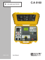
C.A 6160
APPLIANCE MULTITESTER
ENGLISH
User’s Manual
1
CONTENTS
1. GENERAL INTRODUCTION.....................................................................................................................................................................p. 3
1.1
Safety in use...................................................................................................................................................................................p. 3
1.2
Warranty............................................................................................................................................................................................p. 4
1.3
List of measurements carried out by the instrument................................................................................................................p. 4
1.4
List of applicable standards........................................................................................................................................................p. 4
2. DESCRIPTION OF THE INSTRUMENT.................................................................................................................................................p. 5
3. TECHNICAL SPECIFICATIONS..............................................................................................................................................................p. 6
3.1
Withstanding test (PROG. HV and HV position).......................................................................................................................p. 6
3.2
Burn out (HV position)..................................................................................................................................................................p. 6
3.3
Low resistance (Continuity position).........................................................................................................................................p. 7
3.4
Voltage drop scaled to 10A~ (option in Continuity position)..................................................................................................p. 8
3.5
Insulation resistance......................................................................................................................................................................p. 8
3.6
Leakage current..............................................................................................................................................................................p. 9
3.6.1 Leakage current................................................................................................................................................................p. 9
3.6.2 Touch Leakage current.....................................................................................................................................................p. 9
3.6.3 Substitute Leakage current..............................................................................................................................................p. 9
3.7
Functional test.................................................................................................................................................................................p. 9
3.8
Discharge time (DISC. TIME position).......................................................................................................................................p. 10
3.9
General............................................................................................................................................................................................p. 10
4. MEASUREMENTS......................................................................................................................................................................................p. 11
4.1
Withstanding test............................................................................................................................................................................p. 11
4.2
Withstanding test with preset voltage/time diagram..............................................................................................................p. 14
4.3
Low resistance test with current of > 0.1A / 0.2A / 10A / 25A~...............................................................................................p. 16
4.4
Voltage drop scaled to test current of 10A~.............................................................................................................................p. 17
4.5
Insulation resistance......................................................................................................................................................................p. 18
4.6
Discharge time - external (input MAINS TEST)......................................................................................................................p. 20
4.7
Discharge time - internal..............................................................................................................................................................p. 21
4.8
Leakage current.............................................................................................................................................................................p. 22
4.8.1 Leakage current..................................................................................................................................................................p. 22
4.8.2 Touch Leakage current.....................................................................................................................................................p. 23
4.8.3 Substitute Leakage current..............................................................................................................................................p. 24
4.9
Functional test.................................................................................................................................................................................p. 25
4.10 Autotest.............................................................................................................................................................................................p. 26
5. OPERATION.................................................................................................................................................................................................p. 30
5.1
Warnings...........................................................................................................................................................................................p. 30
5.2
Results memorizing.......................................................................................................................................................................p. 31
5.3
Recalling of stored results...........................................................................................................................................................p. 32
5.4
RS 232 Communication...............................................................................................................................................................p. 32
5.5
System configuration.....................................................................................................................................................................p. 33
5.6
Contrast of the display..................................................................................................................................................................p. 36
5.7
Use of remote control pedal.......................................................................................................................................................p. 36
5.8
Use of WRANING LAMP...............................................................................................................................................................p. 37
5.9
Use of barcode reader..................................................................................................................................................................p. 38
5.10 Use of EXT / DOOR input...........................................................................................................................................................p. 38
5.10.1 DOOR input..........................................................................................................................................................................p. 38
5.10.2 EXTERNAL input................................................................................................................................................................p. 38
6. MAINTENANCE..........................................................................................................................................................................................p. 40
6.1
Metrological check........................................................................................................................................................................p. 40
6.2
Service..............................................................................................................................................................................................p. 40
6.3
Cleaning...........................................................................................................................................................................................p. 40
6.4
Replacing the fuses (by properly trained service personnel only!).....................................................................................p. 40
6.5
Replacing the battery (by properly trained service personnel only!)..................................................................................p. 40
6.6
Repairs..............................................................................................................................................................................................p. 40
7. PC SOFTWARE - CE LINK......................................................................................................................................................................p. 41
7.1
Installing CE Link...........................................................................................................................................................................p. 41
7.2
Introduction notes...........................................................................................................................................................................p. 41
7.3
Download data................................................................................................................................................................................p. 42
7.4
Open data file.................................................................................................................................................................................p. 44
7.5
Printing documents........................................................................................................................................................................p. 47
7.5.1 Printing selected rows.......................................................................................................................................................p. 47
7.5.2 Print separately....................................................................................................................................................................p. 48
7.6
Header programming....................................................................................................................................................................p. 49
7.7
Sequence editor..............................................................................................................................................................................p. 50
8. TO ORDER..................................................................................................................................................................................................p. 54
2
1. GENERAL PRESENTATION
1.1
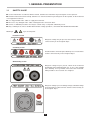
SAFETY IN USE
■ Use the instrument in accordance with the manual, otherwise the instrument may be dangerous for the operator!
■ Read this instruction manual carefully, otherwise use of the instrument may be dangerous for the operator, for the instrument
or
■
■
■
for equipment under test!
Use only grounded mains outlets to supply the instrument!
Do not use any damaged mains outlet or damaged mains connection cable!
Service or calibration procedure must only be carried out by a competent authorized person!
■ Only a skilled person, who is familiar with hazardous voltage operations, can handle APPLIANCE MULTITESTER!
Meaning of
,
signs on front panel :
Insulation section
Dangerous voltage may be present; measurements shall be
carried out only on de-energized object.
Continuity section
Read instructions on how to replace blown-up fuse, measurements
shall be carried out only on de-energized object.
Withstanding section
Dangerous voltage may be present, switch off the instrument
immediately if the red warning lamp (pos. 12, fig. 1) does not light
after switching on HV generator, and service the instrument.
Always handle as the test leads are energized.
Dangerous voltage is present during Leakage, Substitute leakage
and Functional test. Measurements shall be carried out only on
de-energized object.
3
Main plug
Dangerous voltage is present on the FUSES - switch off the
instrument and disconnect all test cables and mains cord before
replacing the fuses or opening the instrument.
1.2
WARRANTY
Unless stated differently, our instruments are guaranteed against any manufacturing or material defect. They do not bear the
specification known as the safety specification. Our guarantee, which may not under any circumstances exceed the amount of the
invoiced price, is for the repair of our faulty equipment only, carriage paid to our workshops. It is applicable for normal use of our
instruments and does not apply to any damage or destruction caused, notably by error in mounting, mechanical accident, faulty
maintenance, defective use, overload or excess voltage.
Our responsibility is strictly limited to the pure and simple replacement of the faulty parts of our equipment; the buyer expressly
renounces any attempt to find us responsible for damages or losses caused directly or indirectly.
Our guarantee is applicable for twelve (12) months after the date at which the equipment is made available. The repair,
modification or replacement of a part during the guarantee period will not result in this guarantee being extended.
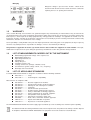
1.3
LIST OF MEASUREMENTS CARRIED OUT BY THE INSTRUMENT
■
■
■
■
■
■
■
■
■
1.4
Withstanding programmed voltage - time sequence test
Withstanding voltage test
High voltage burn-out test
Continuity test
Voltage drop test
Insulation resistance test
Leakage current tests (leakage, substitute, touch)
Functional tests (power, voltage, current, cos ϕ, frequency)
Discharge time measurement
LIST OF APPLICABLE STANDARDS
C.A APPLIANCE MULTITESTER is designed in accordance with the following standards:
■
■
EN 61010-1 ............. safety
EN 61326-1 ............. electromagnetic compatibility
Measurements in compliance with:
■
■
■
■
■
■
■
■
■
■
■
■
■
IEC 60204-1 ............ Electrical equipment of machines
IEC 60335-1 ............ Household and similar electrical appliances
IEC 60439-1 ............ Switch-gear and control-gear assemblies
IEC 60598-1 ............ Luminaries
IEC 60745 ............... Hand-held motor-operated tools
IEC 60755 ............... Residual current operated protect. devices
IEC 60950 ............... Safety of information technology equipment
IEC 61010-1 ............ Safety requirements for electrical equipment
IEC 61029 ............... Transportable motor-operated tools
IEC 61558-1 ............ Transformers and power supply units
EN 60065 ................ Audio, video, and similar electronic apparatus
VDE 701 T1 ............. Repair and modification inspections
VDE 702 T1 ............. Repeat tests of electrical appliances
The APPLIANCE MULTITESTER instrument supply upper standards up to 16A according to its maximum power capability.
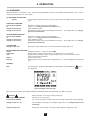
The rubbish bin with a line through it indicates that, in the European Union, the product must undergo selective disposal
in compliance with Directive WEEE 2002/96/EC. This equipment must not be treated as household waste.
4
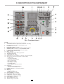
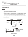
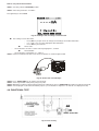
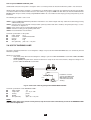
2. DESCRIPTION OF THE INSTRUMENT
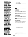
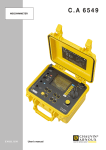
Fig.1. Front panel layout
Legend:
1
LCD dot matrix display with continuous backlight
2
T16A 250V 6.3x32 fuses protect test socket from overloading
3
RS 232 connector to connect external printer or PC
4
EXT/DOOR IN connector
5
BAR CODE READER connector
6
REMOTE connector to connect REMOTE CONTROL PEDAL
7
WARNING LAMP connector to connect WARNING LAMP
8
F 2.5A 250V fuses protect instrument’s power supply
9
POWER ON/OFF indication lamp
10
Mains connector
11
POWER ON/OFF switch with key protection
12
TEST ON warning lamp
13
START/STOP push button
14
General keys F1 to F4 (function of each key is shown on display)
15
SET key (press when the instrument is switched ON):
- Set date / time
- Set serial port baud rate
- Set barcode reader baud rate
- Clear records memory
- Clear devices / records
- Clear program memory
- Load default setting
- INPUT DOOR IN disabled / enabled
16
RS232 key:
- Select RS 232 communication mode
- Transmit memorized data to PC
17
ROTARY SWITCH to select desired function
18
HELP key:
19
MEM key:
- Memorize results
- Recall memorized results
20
WITHSTANDING test terminals
21
DISCHARGE TIME test terminals
22
CONTINUITY current test terminals
23
CONTINUITY potential test terminals
24
INSULATION test terminals
25
TEST SOCKET 230V /16 A
26
TOUCH leakage test terminal
5
3. TECHNICAL SPECIFICATIONS
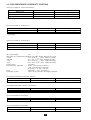
3.1 WITHSTANDING TEST (PROG. HV AND HV POSITION)
Nominal test voltage :
Open circuit test voltage :
Output differential :
Voltage shape:
adjustable (100/5000) V (50,60) Hz at Umains = 230V, Pload = 500VA
Un (nominal test voltage) (-1% / +10%) at Umains = 230V
2HV plugs
sinusoidal
Test voltage readout
Range (kV)
0.100 - 0.999
1.000 - 5.000
Resolution (kV)
0.001
0.001
Accuracy
±(2 % of reading + 5 dig.)
±(3 % of reading + 5 dig.)
Two different voltage procedure modes :
■ Standard voltage mode
■ Programmable voltage mode (parameters t1, t2, t3, U1, U2)
Trip-out out test current for nominal test voltages up to 1000 V adjustable to 0.5, 1.0, 1.5 2.0, 2.5, 3.0, 3.5, 4.0, 4.5, 5.0, 5.5, 6.0, 6.5,
7.0, 7.5, 8.0, 8.5, 9.0, 9.5, 10, 20, 30, 40, 50, 60, 70, 80, 90, 100, 150, 200, 250, 300, 350, 400, 450, 500 mA.
For test voltages greater than 1000 V, maximum current limit depends on max high voltage power characteristic (500 VA = max
power).
Accuracy of trip-out test current: .......................... ±10 % of set value.
Test current readout (sin wave)
Range (mA)
0.0 - 500.0
0.0 - 500.0
Resolution (mA)
0.1
0.1
Accuracy
±(5 % of reading + 5 digit) absolute value
±(30 % of reading +10 digit) resistive or capacitive value**
** not displayed at ‘Trip out ’ STOP
Absolute value of test current is always displayed ( I
A
= I 2R + I C2
) together with selected resistive (
component.
Trip out time: < 30 ms after break through.
Timer: adjustable 1 s - 9 min 59 s with resolution of 1 s. Timer OFF function available.
3.2. BURN OUT (HV POSITION)
Selectable voltage :
Minimum burnout time before overheating:
I max.:
(100 - 5000) V
10 s
(50 - 60) mA
6
) or capacitive (
)
3.3. LOW RESISTANCE (CONTINUITY POSITION)
Resistance readout for current 10 A and 25 A
Range R (Ω)*
0.000 - 0.999
1.000 - 2.000
2.001 - 9.999
Resolution (Ω)
0.001
0.001
0.001
Accuracy
±(3 % of reading + 3 dig.)
±(3 % of reading + 10 dig.)
indicator only
* autoranging
Resistance readout for current 0.10 A
Range R (Ω)*
0.00- 9.99
10.0- 100.0
Resolution (Ω)
Accuracy
0.01
0.1
±(5 % of reading + 12 dig.)
±(5 % of reading + 6 dig.)
* autoranging
Resistance readout for current 0.20 A
Range R (Ω)*
0.00 - 9.99
10.0- 100.0
Resolution (Ω)
Accuracy
0.01
0.1
±(5 % of reading + 6 dig.)
±(5 % of reading + 6 dig.)
* autoranging
Max. output voltage:
<6 V∼
Measuring curr. (electronically stabilized). selectable 100 mA, 200 mA, 10 A, 25 A
- 10 mA
at R < 50 Ω (Umains : 230 V, original test leads)
- 200 mA
at R < 8 Ω (Umains : 230 V, original test leads)
- 10 A
at R < 0.5 Ω (Umains : 230 V, original test leads)
- 25 A
at R < 0.2 Ω (Umains : 230 V, original test leads)
Current shape:
sinusoidal
Threshold value adjustable:
10 mΩ - 1.0 Ω (in steps of 10 mΩ ),
1.0 Ω - 2.0 Ω (in steps of 100 mΩ),
or ignored (*** Ω sign is selected)
Timer:
adjustable 1 s - 59 s, resolution 1 s
Connection system:
4 wire, safety connectors, electrically separated
Test voltage readout with current 10A and 25A
Range (V)
0.000 – 10.000
Resolution (V)
0.001
Accuracy
±(3 % of reading + 0.05 V)
Resolution (V)
0.001
Accuracy
±(5 % of reading + 0.1 V)
Resolution (A)
0.1
Accuracy
±(3 % of reading + 5 dig.)
Resolution (A)
0.001
Accuracy
±(5 % of reading + 5 dig.)
Test voltage readout with current 0.1 A and 0.2 A
Range (V)
0.000 – 10.000
Test current readout 10 A and 25 A
Range (A)
0.0 – 30.0
Test current readout 0.1A and 0.2A
Range (A)
0.000 – 1.000
7
3.4. VOLTAGE DROP SCALED TO 10 A~ (OPTION IN CONTINUITY POSITION)
Voltage drop readout (scaled to 10A~)
Range ∆U (V)
0.00 – 10.00
10.00 – 99.99
Resolution (V)
0.01
0.01
Accuracy
±(3 % of reading + 3 dig.)
indicator only
Resolution (A)
0.1
Accuracy
±(3 % of reading + 3 dig.)
Test current readout
Range (A)
0.0 – 30.0
Threshold value of voltage drop versus wire section:
2
Wire section (mm
0.5
0.75
1
1.5
2.5
4
≥6
Threshold voltage drop (V)
)
5.0
5.0
3.3
2.6
1.9
1.4
1.0
Any of the wire sections in the previous table can be selected in order to evaluate voltage drop result.
Max. output voltage: .................................. 10 V∼
Electronically stabilized current
Current shape: .......................................... sinusoidal
Measuring current (external resist. of (0 - 0.5) Ω connected to original test
cable : ....................................................... >10 A∼
Timer: ........................................................ adjustable (1 - 59) s, resolution 1 s
Connection system: .................................. 4 wire, safety connectors, electrically separated
3.5. INSULATION RESISTANCE
■
Nominal voltage 250 V, 500 V, 1000 V
Insulation resistance readout:
Range* (MΩ)
0.000 - 1.999
2.000 – 199.9
200 - 999
Resolution ** (MΩ)
0.001
0.001, 0.01, 0.1
1
Accuracy
±(5 % of reading + 10 dig.)
±(3 % of reading + 3 dig.)
±(10 % of reading + 10 dig.)
* autoranging, depends on test voltage
** depends on test voltage
Measuring range (stable and accurate result even with capacitive load):
............................................... typ. @ 250 V 5 µF // 1.4 MΩ ; @ 500 V & 1000V 5 µF // 4.2 MΩ
Nominal voltage: ................... (250, 500, 1000) V (+30 % / - 0 %)
Short circuit current: ............... 3.5 mA max.
Measuring current: ................ 1 mA min. at (250, 500, 1000) kΩ load
Settable limits: ....................... (0.2 - 200.0) MΩ (resolution 0.1 MΩ), no limit
(*** MΩ sign is selected)
Timer: ..................................... adjustable 1 s - 9 min 59 s with resolution of 1 s
Timer OFF function available.
Subresult: ............................... measuring voltage
Output: ................................... 2 safety plugs, grounded
Auto-discharge after test.
8
3.6. LEAKAGE CURRENT
3.6.1. LEAKAGE CURRENT
Leakage current readout:
Range (mA)
0.00 – 3.99
4.0 – 20.0
Resolution (mA)
0.01
0.1
Accuracy
±(5 % of reading + 3 dig.)
±(5 % of reading + 3 dig.)
Settable limits: .......................................... (0.1 – 20.0) mA (in step of 0.1 mA)
Output: ...................................................... 16 A power test socket
Timer: ........................................................ adjustable 1 s - 9 min 59 s with resolution 1 s
Timer OFF function available.
3.6.2. TOUCH LEAKAGE CURRENT
Touch leakage current readout:
Range (mA)
0.00 – 2.00
Resolution (mA)
0.01
Accuracy
±(5% of reading + 3digit)
Settable limits:………………. (0.1 – 2.0) mA (in step of 0.1 mA)
Output: ……………………….16 A power test socket + TOUCH safety plug
RAmeter: 2 kΩ
3.6.3. SUBSTITUTE LEKAGE CURRENT
Substitute leakage current readout:
Range (mA)
0.00 –20.0
Resolution (mA)
0.01
Accuracy
±(5% of reading + 3digit)
Settable limits: …………………… (0.1 – 20.0) mA (in step of 0.1 mA)
Short circuit current:……………… < 30 mA
Open circuit voltage :……………. 40 V
Output: …………………………….16 A power test socket
Displayed current is calculated to 230 V
3.7. FUNCTIONAL TEST
Active Power, Apparent Power, Voltage, Current and Frequency monitoring on the test socket :
Active Power, Apparent Power
Range (W)
0 – 199.9
200 – 3500
Resolution (W)
0.1
1
Accuracy
±(5 % of reading + 10 digit)
±(5 % of reading + 3 digit)
Resolution (V)
1
Accuracy
±(2 % of reading + 2 digit)
Resolution (A)
0.001
0.01
Accuracy
±(3 % of reading + 5 dig.)
±(5 % of reading + 5 dig.)
Resolution
0.01
Accuracy
±(3 % of reading + 3 dig.)
Test voltage readout
Range (V)
0 – 400 V
Test current readout
Range (A)
0 – 0.999
1.00 – 15.99
Cos ϕ readout
Range
0 – 1.00
9
Frequency readout
Range (Hz)
45.00 – 65.00
Resolution (Hz)
0.01
Accuracy
±(0.1% of reading +3 dig.)
Threshold Apparent Power: ................................. adjustable
(10 - 3500) VA
(10 - 100) VA (resolution 1 VA)
(100 - 3500) VA (resolution 10 VA)
Output: ................................................................. 16 A power test socket
Timer: ................................................................... adjustable 1 s - 9 min 59 s with resolution 1 s
Timer OFF function available.
3.8. DISCHARGE TIME (DISC.TIME POSITION)
■
Discharge time on power plug (external)
Max. working voltage ....................................................... 600 V p
Min. working voltage ........................................................ (60, 120) V p
Measuring range ............................................................. (0 - 10) s
Resolution ....................................................................... 0.1 s
Threshold of discharging time ......................................... 1 s
Accuracy .......................................................................... ±(2 % of reading + 0.2 s)
Safe voltage level ............................................................ 60 V, 120 V
Internal resistance of input .............................................. 96 MΩ
■
Discharge time on internal electronic components (internal)
Max. working voltage ....................................................... 600 V p
Min. working voltage ........................................................ (60,120) V p
Measuring range ............................................................. (0 - 10) s
Resolution ....................................................................... 0.1 s
Threshold of discharging time ......................................... 5 s
Accuracy .......................................................................... ±(2% of reading + 0.2 s)
Safe voltage level ............................................................ 60 V, 120 V
Internal resistance of input .............................................. 96 MΩ
3.9. GENERAL
Mains voltage: ................................................................. 230 V (-10 % - +6 %) / (50,60) Hz
Max. power consumption: ................................................ 660 VA (without load on TEST SOCKET)
Display: ............................................................................ LCD dot matrix, (160 x 116) dots with cont. backlight
RS232 interface: .............................................................. 1 start bit, 8 data bits, 1 stop bit
RS232 baud rate adjustable: .......................................... 9600, 19200, 38400 Baud
Memories: ........................................................................ 1638 memory locations
Remote control signals: ................................................... START / STOP, SAVE
EXT/ Door in signals: ....................................................... Next test, Good / Bad result, External input, Door in
Bar code reader: .............................................................. EAN13
Bar code baud rate adjustable: ....................................... 2400, 4800 or 9600 Baud
Measurement circuitry protection:
F3 .................................................................................. F 2.5 A / 250 V (5 × 20) mm (general protection of the instrument)
F4 .................................................................................. F 2.5 A / 250 V (5 × 20) mm (general protection of the instrument)
NOTE !
For correct operation of the instrument fuses F3 and F4 must be in good condition because the test socket is the point from
which the instrument observes the input voltage (zero crossing for soft start of internal generator).
Case: ............................................................................... shock proof plastic / portable
Dimensions (w × h × d): ................................................... (410 × 175 × 370) mm
Mass (without accessories): ............................................ 13.5 kg
Pollution degree: ............................................................. 2
Degree of protection (at closed cover): ........................... IP 50
Overvoltage category: ..................................................... Cat III / 300V, Cat II / 600V
Protection classification: .................................................. I
Working temp. range: ....................................................... (0 - +40) 0C
Ref. temp. range: .............................................................. (+5 - +35) 0C
Ref. humidity range: ......................................................... (+40 - +70) % RH
Storage temp. range: ....................................................... (-10 - +60) 0C
Max. working humidity: .................................................... 85% RH (0 - +40) 0C
Max. storage humidity: ..................................................... 90% RH (-10 - +40) 0C
80% RH (+40 - +60) 0C
10
Accuracies apply for 1 year in reference conditions. Temperature coefficient outside this limits is 0.1% of measured value per 0C°
and 1 digit.
Withstanding proof test:
■ Between mains and withstanding terminals
7500 Veff / 1 min
Between mains and other terminals or accessible metallic parts 2200 Veff / 1 min
4. MEASUREMENTS
4.1. WITHSTANDING TEST:
WARNING !
•
•
•
•
•
•
Only a skilled person, who is familiar with hazardous voltage operations, can perform this measurement!
Check instrument and test leads for any sign of damage or abnormality before connecting them to the instrument.
DO NOT use test probes in case of any damage or abnormality!
Always handle the instrument and connected accessories as the Withstanding test sockets and leads are under
the hazardous voltage!
Never touch exposed probe tip, connected equipment under test or any other energized part during the
measurements. Make sure that NOBODY can contact them either!
Connect test probes only for withstanding measurement, and disconnect them immediately after the test!
DO NOT touch any part of test probe in front of the barrier (keep your fingers behind the finger guards on the probe)
– possible danger of electric shock!
Always set the lowest possible trip-out current.
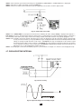
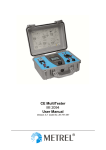
HV (high voltage) position
APPLIANCE MULTITESTER
C.A 6160
OBJECT UNDER TEST
iC
0 - 230V / 50,60 Hz
regulated
V
iR
100V - 5 kV
CLOAD
A
RLOAD
iA
Fig. 2. Test circuitry
0
iR
Re
iA
iA= iC + iR
iA.....absolute value of test current
iC
iC.....capacitive current
iR.....resistive current
-jIm
Fig. 3. Test current diagram
11
How to carry out the measurement
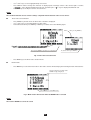
STEP 1. Set rotary switch to HV (high voltage) position. The following heading is displayed:
Function name
Tripping out current
Nominal test voltage
Leakage current
(main result)
Character of selected part of leakage current
Selected (resistive or capacitive)
part of leakage current
Set timer value
Test voltage
Timer key to set timer
value or to switch it on/off
Un key to select
nominal test voltage
Burn key to set burn mode
Ilim key to select tripping out
current or to select character
of displayed leakage current
Fig. 4. Main menu in HV function
STEP 2. Select test parameters as follows:
■ Test voltage
Use UN key to select appropriate test voltage that can be set using ↑ ↓ keys from 100 V to 1000 V in 10 V steps and from
1000 V to 5000 V in 50 V steps.
Selected test voltage
Fig. 5. Test voltage selection menu
■
Press Exit key to exit Test voltage selection menu.
Trip-out current / character of displayed part of leakage current
Press Ilim key in order to reach menu for trip-out current selection and character of displayed part of leakage current
(resistive or capacitive). See the following figure.
Selected tripping out current
Absolute value of test current
Character of selected part of leakage current
Fig. 6. Trip-out current selection menu
12
-
Use ↑ and ↓ keys to select appropriate trip-out current.
Press Chr I in order to change the character of displayed part of leakage current. If the selected part is resistive,
sign is displayed behind mA unit. For capacitive part
sign is displayed behind mA unit.
Press Exit key to exit Trip-out current selection menu.
NOTE !
The set threshold value of test current is always compared with the absolute value of test current.
Timer value / timer OFF/ON
■
-
Press Timer key and the menu for timer value selection is displayed.
Use ↑ and ↓ keys to select appropriate test time value.
To deactivate the timer press Toff key or Ton key to activate it. See the following figure.
After pressing Toff key
After presing Toff key test time is not displayed
To activate timer press Ton key
Fig. 7. Timer value selection menu
-
Press Exit key to exit Timer value selection menu.
BURN mode
■
-
Press Burn key to select Burn out mode. In this mode current is limited only by the internal generator characteristics.
Instead of tripping out current value
BURN message is displayed
Press Ilim key to cancel Burn mode
Fig. 8. Main menu in HV function when the BURN mode is selected
NOTE !
The result of BURN test cannot be saved
13
STEP 3. Connect test probes (pistols) to the instrument as shown in figure below.
Fig. 9. Connection of test probes
STEP 4. Close DOOR IN safety connector, if enabled. (CONTINUITY test terminals must be open).
STEP 5. Press START/STOP key to start high voltage generator and carry out the test using test probes.
STEP 6. Wait for the test time to elapse (if the timer has been switched on) or press START/STOP key again to stop high voltage
generator.
NOTES !
■
■
■
■
■
Take care when using HV test pistols - hazardous voltage!
Use timer ON mode or optional REMOTE CONTROL pedal to stop the measurement when test probes are still
connected to equipment under test. The displayed result obtained in this way can be stored to memory for
documentation purposes.
It is advisable to connect test pistols to the equipment under test before pressing START/STOP pedal to avoid
sparking and trip out of the HV generator.
It is advisable to use the optional WARNING LAMP connected to the instrument, especially if the measurements
are to be done away from the instrument using optional test probes with longer cables.
If there is a test current higher than the preset limit, HV generator trips automatically after reaching that value.
Preset limit value is displayed as a result in this instance.
STEP 7. Save displayed result for documentation purpose (see instruction in chapter 5.2. on how to save displayed result).
4.2. WITHSTANDING TEST WITH PRESET VOLTAGE/TIME DIAGRAM:
WARNING !
■
Only a skilled person, who is familiar with hazardous voltage operations, can perform this measurement!
■
Check instrument and test leads for any sign of damage or abnormality before connecting them to the instrument.
DO NOT use test probes in case of any damage or abnormality!
■
Always handle the instrument and connected accessories as the Withstanding test sockets and leads are under
the hazardous voltage!
■
Never touch exposed probe tip, connected equipment under test or any other energized part during the
measurements. Make sure that NOBODY can contact them either!
■
Connect test probes only for withstanding measurement, and disconnect them immediately after the test!
DO NOT touch any part of test probe in front of the barrier (keep your fingers behind the finger guards on the probe)
– possible danger of electric shock!
Always set the lowest possible trip-out current.
■
PROG.HV (programmed HV) position
How to carry out the measurement
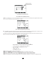
STEP 1. Set rotary switch to PROG.HV (high voltage) position, the following heading is displayed:
14
Tripping out current
Prog key to select programing menu
Fig. 10. Main menu in PROG.HV function
STEP 2. Press Prog. key to set or to check programmed ramp values in order to prevent damage to the equipment under test (last
values used are memorized). Select test parameters as follows:
Fig. 11. Menu for programming ramp values
■
Press Ilim key in order to reach menu for trip-out current selection and character of displayed part of leakage current
(resistive or capacitive). The same procedure as for Ilim selection at HV function applies.
To change U and T values press U/T key. Value T2 represent time from t1 to t2 and value T3 represent time from t2 to t3. (fig. 12).
Menu for selection and changing values is displayed, see the following figure:
Fig. 12. Timer T1 is selected, change value by using ↑ ↓ keys
-
To select ramp times or voltage values press Sel. key.
Use ↑ and ↓ keys to set appropriate test value:
Time: (1 s - 240 s)
Voltage: 100 V –5 kV
Press Exit key (2x) to exit.
STEP 3. Connect test probes (pistols) to the instrument.
STEP 4. Close DOOR IN safety connector, if enabled. (CONTINUITY test terminals must be open).
STEP 5. Press START/STOP key to start high voltage generator and carry out the test using test probes.
STEP 6. Wait for the test time to elapse or press START/STOP key again to stop high voltage generator.
STEP 7. Save displayed result for documentation purpose (see instruction in chapter 5.2. on how to save displayed result).
15
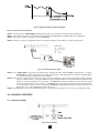
4.3. LOW RESISTANCE TEST WITH CURRENT OF >0.1A / 0.2A / 10A / 25A~
CONTINUITY position
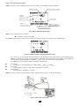
Fig. 13. Test circuitry
How to carry out the measurement
STEP 1. Set rotary switch to Continuity position. The following heading is displayed.
Function name;
CONTINUITY for continuity mode
VOLT. DROP for voltage drop mode
Threshold resistance
Resistance
(main result)
Test current
Test voltage
Set timer value
In key to select
test current
Timer key to set timer
value or to set AUTO mode
Rmax key to set
threshold resistance
Vdrop key to select Voltage drop mode
Fig. 14. Main menu in Continuity function
STEP 2. Select test parameters as follows:
■Measurement current
Use In key to select appropriate measurement current.
■Resistance threshold
Press Rmax key in order to reach the menu for selection of resistance threshold (see the following figure).
Fig. 15. Low resistance threshold selection menu
16
- Use ↑ and ↓ keys to select appropriate threshold value. If the displayed result is higher than the set threshold limit, the result will
be accompanied by an error sound signal (after completion of the measurement). No threshold value will be selected and no
sound signal will be activated when « ∗∗∗ Ω» is selected instead of threshold limit.
- Press Exit key to exit Low resistance threshold selection menu.
■Timer value + AUTO start option
Press Timer key and the menu for selection of timer value is displayed.
After pressing Exit
"Make connection !"message
will be displayed
Fig.16. Timer value selection menu with auto option
-
Use ↑ and ↓ keys to select appropriate test time value.
To activate the measurement automatically when the instrument is connected to the equipment under test press the
Auto key. In this mode a small voltage value is always present on the continuity test terminals. The flow of a small current
across the tested item when the test terminals are connected will activate the measurement. By turning the ROTARY
SWITCH or switching off the instrument the AUTO function is automatically disabled.
STEP 3. Connect test probes to the instrument and to the tested item as shown in the figure below.
Fig. 17. Connection of test leads
STEP 4. Press START/STOP key to start the measurement.
STEP 5. Wait for the set time to elapse or press START/STOP key again to stop the measurement.
STEP 6. Save displayed result for documentation purpose (see instruction in chapter 5.2. on how to save displayed result).
NOTE !
Test results can be adversely affected by impedances of additional operating circuits connected in parallel with the tested
device or by transient currents.
4.4. VOLTAGE DROP SCALED TO TEST CURRENT OF 10 A~
CONTINUITY position
How to carry out the measurement
STEP 1. Set rotary switch to CONTINUITY position, press Vdrop key. The following heading is displayed.
17
Threshold voltage drop/wire section
Voltage drop scaled
to 10A (main result)
Set timer value
Test current
Test voltage
AUTO mode is selected
dU/S key to set threshold
value of voltage drop
Timer key to set timer
value or to cancel AUTO mode
Rcont key to return into Continuity menu
Fig. 18. Main menu in Voltage drop function
STEP 2. Select test parameters as follows:
-
Voltage drop threshold.
Use dU/S key to select appropriate threshold, see the table in paragr. 3.4.
■ Timer value + AUTO start option
See instructions in paragraph 4.3.
STEP 3. Connect test probes to the instrument and to equipment under test as shown in the following figure:
Fig. 19. Connection of test leads
STEP 4. Press START/STOP key to start the measurement.
STEP 5. Wait for the set time to elapse or press START/STOP key again to stop the measurement.
STEP 6. Save displayed result for documentation purpose (see instruction in chapter 5.2. on ow to save displayed result).
NOTE !
Test results can be adversely affected by impedances of additional operating circuits connected in parallel with the tested
device or by transient currents.
4.5. INSULATION RESISTANCE
Fig. 20. Test circuitry
18
How to carry out the measurement
STEP 1. Set rotary switch to ISO (insulation resistance) position, the following heading is displayed
Nominal test voltage
Threshold insulation resistance
Insulation
resistance
Measured test voltage
Set timer value
Un key to set
nominal test voltage
Timer key to set timer
value or to switch it on/off
Rmin key to set
threshold insulation resistance
Fig. 21. Basic heading in ISO function
STEP 2. Select test parameters as follows:
■ Insulation resistance threshold
Press Rmin key in order to reach menu for selection of insulation resistance threshold, see the following figure.
Fig. 22. Insulation resistance threshold selection menu
-
■
■
■
Use ↑ and ↓ keys to select appropriate threshold value. If the displayed result is lower than the set threshold limit value,
it will be accompanied by an error sound signal (after completion of the measurement). There will be no threshold value
selected and no sound signal will be activated if «*** MΩ» sign is selected instead of threshold limit.
Press Exit key to exit Insulation resistance threshold selection menu.
Test voltage
Use Un key to select appropriate test voltage (250V , 500V
or 1000V
Timer value
See instructions on how to set the value in paragraph 4.1. STEP 2.
Timer ON/OFF
See instruction in paragraph 4.1. STEP 2.
).
STEP 3. Connect test probes to the instrument and to equipment to be tested as shown in figure below:
Fig. 23. Connection of test leads
19
STEP 4. Press START/STOP key to start the measurement.
STEP 5. Wait for test time to elapse (if the timer has been switched on) or press START/STOP key again to stop the
measurement.
STEP 6. Save displayed result for documentation purpose (see instruction in chapter 5.2. on how to save displayed result).
NOTE !
Do not disconnect measured object before it is discharged.
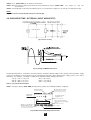
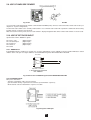
4.6. DISCHARGE TIME - EXTERNAL (INPUT MAINS TEST)
Fig. 24. Test circuitry
, 120V
Fig. 25. Voltage on MAINS TEST input
External discharge time is calculated as the input voltage is maximum allowed voltage of the currently connected mains supply
system. The instrument is constructed to measure external discharge time in three different mains supply systems (115 V, 230 V
and 400 V). The voltage is calculated according to the following nominal voltage peak values:
179 Vp = (115 V + 10 %)x√2
(60 V < Up < 235 V)
344 Vp = (230 V + 6 %)x√2
(235 V < Up < 425 V)
596 Vp = (400 V + 6 %)x√2
(425 V < Up < 600 V)
How to carry out the measurement
STEP 1. Set rotary switch to DISC.TIME (discharge time) position. The following heading is displayed.
External measuring
Threshold values in external
Discharge time
(main result)
Present voltage peak
during the test
Line reserved for messages:
ready, start, repeat, low Voltage,
timeout
Ulim
Syst. key to select internal or
external measuring system
Ulim key to select 60 V or 120 V
measuring system
Fig. 26. Main menu in Discharge time function
20
STEP 2. Select external system measurement by pressing SYST. key (exter. 60 V 1 s or exter. 120 V 1 s is displayed).
STEP 3. Select 60 V or 120 V measuring system using Ulim key.
STEP 4. Connect test cable to the instrument and to the equipment to be tested as shown in figure below.
Fig. 27. Connection of test cable
STEP 5. Press START/STOP key to prepare the instrument for switching off mains voltage. Ready is displayed after approx 1 s.
Low Voltage message is displayed if the voltage on input mains is not appropriate (less than min working voltage) or the input is
not connected to the mains (check input circuit, mains voltage, double connection element is not properly plugged in, etc.).
STEP 6. Pull out double connection element and wait for the result to be displayed. If the disconnection voltage is high enough
to carry out a measurement, (see fig. 25) Start message is displayed and the measurement will be performed. If the
voltage is not high enough then the result of 0.0 s and Repeat message are displayed. In this instance repeat
measurement from STEP 3. If the result 0.0 s and Repeat message reappears repeat measurement 5 to 10 times
successively, the result 0.0. it can be accepted as valid. Timeout is displayed if the double connection element is not
pulled out in 10 s, or discharging time is higher than 10 s.
STEP 7. Save displayed result for documentation purposes (see instructions in chapter 5.2. on how to save displayed result).
4.7. DISCHARGE TIME-INTERNAL
Fig. 28. Test circuitry
expected
Line voltage
Fig. 29. Expected voltage on tested object input
21
,120 V
Fig. 30. Expected voltage on discharge input
How to carry out the measurement
STEP 1. Set rotary switch to DISC.TIME (discharge time) position. The heading according to fig.26 is displayed.
STEP 2. Select internal system measurement by pressing SYST. key (inter. 60 V 5 s or inter. 120 V 5 s is displayed).
STEP 3. Select 60 V or 120 V measuring system using Ulim key.
STEP 4. Connect test cables to equipment under test and the tested item to line voltage as shown in figure below.
Fig. 31. Connection of test cables
STEP 5. Press START/STOP key to prepare the instrument for switching off mains voltage. Ready is displayed after 1 s approx.
Low Voltage message is displayed if the voltage on input mains is not appropriate (less than min working voltage)
or not connected (check input circuit, mains voltage).
STEP 6. Pull out power supply connector and wait for the result to be displayed. If the disconnection voltage is high enough to
carry out a measurement, (see fig. 25) Start message is displayed and the measurement will be performed. If the
voltage is not high enough then the result 0.0 s and Repeat message are displayed. In this instance repeat
measurement from STEP 3. If the result 0.0 s and Repeat message reappears repeat measurement 5 to 10 times
successively, the result 0.0. it can be accepted as valid. Timeout is displayed if the double connection element is not
pulled out in 10 s, or discharging time is higher than 10 s.
STEP 7. Save displayed results for documentation purpose (see instruction in chapter 5.2. on how to save displayed results).
4.8. LEAKAGE CURRENTS
4.8.1. LEAKAGE CURRENT
Fig. 32. Test circuitry
22
How to carry out the measurement
STEP 1. Set rotary switch to LEAKAGE position. The following heading is displayed.
Threshold value of leakage current
Measured
leakage current
Syst. key to select desired
type of leakage measurement
(Leakage, Substitute, Touch)
Timer key to set timer
value or to switch it on/off
Ilim key to set
threshold leakage current
Fig. 33. Main menu in Leakage current function
STEP 2. Select test parameters as follows:
■
■
Pres Syst. key to select leak
Leakage current threshold
Press Ilim key to open menu to change leakage current threshold value.
Use ↑ and ↓ keys to select appropriate threshold value.
Press Exit key to exit menu.
■
Timer value
See instructions on how to set the value in paragraph 4.1., STEP 2.
■
Timer ON/OFF
See instructions in paragraph 4.1., STEP 2.
STEP 3. Connect tested item into test socket on the instrument as shown in figure below.
Pmax = 3.5 kVA
Fig. 34. Connection of tested object
STEP 4. Press START/STOP key to start the measurement.
STEP 5. Wait for the test time to elapse (if the timer has been switched on) or press START/STOP key again to stop the measurement.
STEP 6. Save displayed result for documentation purpose (see instructions in chapter 5.2. on how to save displayed result).
4.8.2. SUBSTITUTE LEAKAGE CURRENT
Fig. 35. Test circuitry
23
How to carry out the measurement
STEP 1. Set rotary switch to LEAKAGE position.
STEP 2. Select test parameters as follows:
Pres Syst. Key to select subst
Fig. 36. Heading in Substitute Leakage current function
Set Leakage current threshold
Press Ilim key to open menu to change leakage current threshold value.
Use ↑ and ↓ keys to select appropriate threshold value.
Press Exit key to exit menu.
■
-
■
Timer value
See instructions on how to set the value in paragraph 4.1. STEP 2.
-
■
Timer ON/OFF
See instructions in paragraph 4.1. STEP 2.
STEP 3. Connect tested item into test socket on the instrument as shown in figure below.
Fig. 37. Connection of tested object
STEP 4. Press START/STOP key to start the measurement.
STEP 5. Wait for the test time to elapse (if the timer has been switched on) or press START/STOP key again to stop the measurement.
STEP 6. Save displayed result for documentation purpose (see instruction in chapter 5.2. on how to save displayed result).
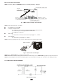
4.8.3. TOUCH LEAKAGE CURRENT
APPLIANCE MULTITESTER
C.A 6160
TOUCH
Touch leakage
cca 2K
TEST
SOCKET
Fig. 38. Touch leakage test circuitry
24
separated metal
part
How to carry out the measurement
STEP 1. Set rotary switch to LEAKAGE position.
STEP 2. Select test parameters as follows:
Pres Syst. Key to select touch
Fig. 39. Heading in Touch Leakage current function
Set Leakage current threshold
Press Ilim key to open menu to change touch leakage current threshold value.
Use ↑ and ↓ keys to select appropriate threshold value.
Press Exit key to exit menu.
■
-
■
Timer value
See instructions on how to set the value in paragraph 4.1., STEP 2.
■
Timer ON/OFF
See instructions in paragraph 4.1., STEP 2.
STEP 3. Connect tested item into test socket on the instrument as shown in figure below.
Fig. 40. Connection of tested object
STEP 4. Press START/STOP key to start the measurement.
STEP 5. Touch ungrounded metal part by using test probe.
STEP 6. Wait for the test time to elapse (if the timer has been switched on) or press START/STOP key again to stop the measurement.
STEP 7. Save displayed result for documentation purpose (see instruction in chapter 5.2. on how to save displayed result).
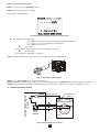
4.9. FUNCTIONAL TEST
Fig. 41. Test circuitry
25
How to carry out the measurement
STEP 1. Set rotary switch to FUNCTION. TEST position, the following heading is displayed.
Values related to tested object
Apparent power threshold value
Tested object current
Line voltage
Active power
Apparent power
Frequency
Power factor
Timer key to set timer
value or to switch it on/off
Limit key to set
threshold value
Fig. 42. Main menu in Functional test function
STEP 2. Select test parameters as follows:
■
Apparent power threshold value
Press Limit key to open menu for changing power threshold value.
Use ↑ and ↓ keys to select appropriate threshold value.
Press Exit key to exit menu.
■
Timer value
See instructions on how to set the value in paragraph 4.1., STEP 2.
■
Timer ON/OFF
See instructions in paragraph 4.1. STEP 2.
STEP 3. Connect the tested equipment into test socket on the instrument as shown in Leakage current paragraph.
STEP 4. Press START/STOP key to start the measurement.
STEP 5. Wait for the test time to elapse (if the timer has been switched on) or press START/STOP key again to stop the measurement.
STEP 6. Save displayed result for documentation purposes (see instructions in chapter 5.2. on how to save displayed result).
NOTE !
A message ‘’ Load on TEST SOCKET ‘’ is displayed if the ROTARY SWITCH is in positions PROG. HV, HV, CONTINUITY, ISO,
or AUTO, and load is present on TEST SOCKET.
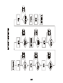
4.10. AUTOTEST
Autotest is a very powerful tool, which is constructed to make the process of measurement easier, more flexible or even automatic.
It gives an assurance that the complete measurement procedure is carried out. Any previously designed sequence by CE Link
software (up to 10 sequences, each composed of up to 50 steps can be saved in APPLIANCE MULTITESTER memory) will be
executed step by step. Every measurement result, which has not passed, will be signaled and the automatic procedure will be
stopped. When the user removes the cause of the error, he can continue the procedure by pressing START button. In this way the
user is sure that every step will be completed with PASS result. The user can decide to skip the failed measurement using SKIP
command on the instrument. The result of skipped measurement is not saved into the memory.
When REMOTE CONTROL PEDAL is used and the procedure is stopped at PAUSE or MESSAGE step of sequence, you can
continue the procedure only by pressing START button on the instrument.
Rotating the rotary switch during autotest sequence execution is not allowed, otherwise the instrument can block up.
Autotest is a very useful tool for the production line output check of manufactured products, or for laboratory verification that the
tested electrical machine meets the appropriate standard. The results of output check can be downloaded (or auto-downloaded
, after every tested product) to PC for documentation purpose. Auto-repeat and auto print function after each sequence can be
selected in PC software. It is intended to automate the product line checking.
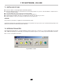
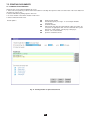
The only way to create autotest sequence is to use Sequence editor in CE Link PC software (32-bit application for Windows) see
picture below.
26
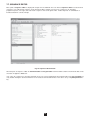
Fig. 43. Main CE Link window
For more information on options in sequence editor see chapter 7, PC software - CE Link. When the sequence is completed it
must be sent to APPLIANCE MULTITESTER by using serial RS232 interface. After sending it, the PC does not need to be
connected to the APPLIANCE MULTITESTER.
How to carry out the measurement
STEP 1. Install CE Link PC software on your PC.
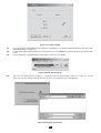
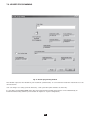
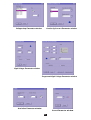
STEP 2. Using Sequence editor, create the desired sequence. Max. number of steps for each sequence is 50 including
programmed pause, messages, barcode reader sequence, sound signals etc.
Fig. 44. Sequence editor window
STEP 3. Set rotary switch on the instrument to AUTOTEST position, the heading in fig.45 is displayed.
Fig. 45. Main menu in Autotest function
(initially no program loaded)
27
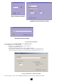
STEP 4. Send programmed sequence to DIELECTRIC STRENGTH TESTER from “List of instrument’s programs” menu by
using Send button. After the transfer is completed the name of the user designed procedure is displayed on the list of
programs. Up to 10 sequences can be sent to the instrument.
Press View key to
view sequence steps
Fig. 46. Sequence name is displayed, to display individual steps press View key
STEP 5. Press START/STOP key to start the measurements that compose the sequence.
NOTE !
Do not rotate the rotary switch during executing autotest sequence, otherwise the instrument can block up!
SEQUENCE EXAMPLE
Sequence example illustrates usage of AUTOTEST function at testing Luminaries according to IEC 60598-1 standard.
STEP 1. BAR CODE READER (optional reading of bar code to memory),
STEP 2. PAUSE {(1 - 600) s or Wait for key} (to check device is ready for CONT test),
STEP 3. CONTINUITY 10 A {I: 10 A; Rlim: 0.5 E; time: 1 s},
STEP 4. MESSAGE {ISO: L+N to PE} (notice to prepare device for ISO test),
STEP 5. INSULATION 500 V {Rlim: 2 M; time: 10 s},
STEP 6. MESSAGE {HV: L+N to grounded case} (notice to prepare device for HV test),
STEP 7. WITHSTANDING {U: 1.5 kV; Ilim: 5 mA; time: 60 s},
STEP 8. MESSAGE {HV: L+N to nongr. case} (notice to prepare device for HV test),
STEP 9. WITHSTANDING {U: 3.7 kV; Ilim: 5 mA; time: 60 s},
STEP 10. WAIT FOR EXTERNAL INPUT sequence will be continued after external impulse,
STEP 11. DISCHARGE Internal {U: 60 V; t: 5 s},
STEP 12. MESSAGE {LEAK.: L to PE; FUNCT.} (notice to prepare device for DISCH test and after PAUSE for FUNCT. Test),
STEP 13. LEAKAGE CURR. {Ilim: 1 mA; time: 5 s},
STEP 14. PAUSE {2 s},
STEP 15. FUNCTIONAL TEST {Plim: depend on luminary; t: 10 s},
STEP 16. SOUND SIGNAL {t: 1 s} (notice after conclusion of testing),
STEP 17. MESSAGE {Testing successfully done}.
STEP 18. WAIT FOR EXTERNAL INPUT sequence will be continued after external user’s signal,
STEP 19. PROGRAM SETTINGS {Luminary test 1},
How to create sequence
Define all requested tests with their limits according to desired standard and tested device and arrange them into a sequence by
logical order. Use PAUSE, MESSAGE, or WAIT FOR EXTERNAL INPUT functions between different tests to notify operator to
prepare tested device for the appropriate following test.
Select Auto repeat option in Program settings to restart the sequence after it is done without pressing START button. Select Save
measurements and Auto send options to send memorized results to PC after the sequence is done. CE Link enables to print Test
Report after the results are received. All this functions together enable fully automated testing of products in production line.
It is possible to manufacture test accessory (relay matrix) for suitable connection between tested device and APPLIANCE
MULTITESTER. The equipment must be manufactured by customer according to their needs. It can be controlled by EXT output
of APPLIANCE MULTITESTER through PIN 3 (Wait for external input) input signal and PIN 4 (Next test) output signal.
28
29
5. OPERATION
5.1. WARNINGS
Different warnings or information can be reported during manipulation with the APPLIANCE MULTITESTER. Here is a list of
warnings and information for each function.
HV AND PROG.HV FUNCTION:
Trip out
CONTINUITY FUNCTION:
Load on TEST SOCKET
or
Voltage on term. C1-C2
Voltage on term. P1-P2
VOLTAGE DROP FUNCTION:
Load on TEST SOCKET
or
Voltage on term. C1-C2
Voltage on term. P1-P2
ISO FUNCTION:
Voltage on term. ISO
The HV generator tripped-out due to the test current, which was higher than the set threshold
value.
External AC voltage connected to CONTINUITY
input C1 – C2 (voltage present on P1 and P2 too), or
TEST SOCKET loaded.
External AC voltage connected to CONTINUITY input P1 – P2 is higher than 12 V (voltage
present on C1 and C2 too).
External AC voltage connected to CONTINUITY
input C1 – C2, (voltage present on P1 and P2 too) or
TEST SOCKET loaded.
External AC voltage connected to CONTINUITY input P1 – P2 is higher than 12 V (voltage
present on C1 and C2 too).
External AC or DC voltage connected to ISO terminals is higher than 30 V.
DISCHARGING TIME FUNCTION:
Ready
displayed for approx. 1 s after pressing START.
Low Voltage
displayed if the voltage on input mains is not appropriate or not connected.
Start
displayed if disconnection voltage is high enough to carry out measurement, and the
measurement will be performed.
Repeat
repeat measurement.
Time out
displayed if the connection element is not pulled out in 10 s or discharging time is higher then
10 s.
GENERAL:
HOT
The instrument is overheated (CONTINUITY, VOLT.DROP, HV and PROG.HV);
sign is
also displayed.
Fig. 47. Example of hot message
Measurements in functions ISO, LEAK.CURRENT, FUNCTION. TEST and DISC.TIME can still be carried out.
No Earth
Earth connection is missing on mains power plug.
No Voltage on TEST SOCKET
Load on TEST SOCKET
Check Fuses F3, F4 (16 A T).
Test socket is loaded in functions other then Leakage, Disch. time and Functionality.
Voltage on term. P1 - P2
Ext. AC voltage connected to P1-P2 input is higher than 12 V (voltage present on C1
and C2 too).
Voltage on term. ISO
External AC or DC voltage connected to ISO terminals is higher than 30V.
30
5.2. RESULTS MEMORIZING
Each displayed result can be stored to one of 1638 memory locations. In addition to the main result all subresults and test
parameters are also saved and can be recalled and downloaded to PC. Each result is marked with memory index (Memory:______),
device number (Device:______) and device barcode number (Barcode:______).
Memory: z
Memory: 0003
Memory: 0002
Memory: 0001
Memory: y
Memory: 0003
Memory: 0002
Memory: x
Barcode: from device 255
Memory: 0003
Device: 255
Barcode: from device 002
Memory: 0002
Device: 002
Barcode: from device 001
Memory: 0001
Device: 001
Memory: 0001
The device number can be set from 001 up to 255 and there are memory indexes that belong to each device, which can be set
from 001 up to 1638 until the whole storage is occupied.
Fig. 48. Presentation of memory organization
How to save displayed results
The displayed result can be saved only after the measurement is complete.
STEP 0. Carry out the measurement.
STEP 1. Press MEM key in order to reach memory menu for saving results (see fig. below).
Device number
Bar code number for
displayed device
Number of memorized results
under displayed device number
MEM key to select
memory operation menu
Fig. 49. Memory heading for saving results
STEP 2. Select device using ↑ and ↓ keys (default device is the last device used).
■ Device number, Barcode from device and number of saved measurement on this device is displayed.
■ See instruction in chapter 5.9. for how to get barcode number .
STEP 3. Press MEM key to save measured values / (Press Exit key to skip saving).
■ After pressing MEM key memory menu will be automatically closed.
NOTES !
Memorizing procedure can be easily accomplished by pressing MEM key twice when the user does not want to change the
device (in this case the user can skip the procedure for device setting because the instrument will automatically set the
last device used).
■ Each displayed result can be stored only once (in order to avoid double storing by mistake).
■ Any further pressing of MEM key will enable only memory recall (recall from memory menu will be displayed).
■ The result of BURN test cannot be saved.
31
5.3. RECALLING OF STORED RESULTS
The results can be recalled only before the measurement is performed or after the result is saved.
STEP 1. Press MEM key in order to reach memory menu for recalling results (see fig. below).
Fig. 50. Memory heading for recalling from memory
STEP 2. Select device using ↑ and ↓ keys.
■ If for some reason the device has to be cleared press ClrDev key, (“press ClrDev to confirm” message will be displayed
to prevent clearing by mistake). Press ClrDev key to confirm or Exit to cancel clearing procedure.
STEP 3. Press MEM key to recall saved results under chosen device.
Fig. 51. Recalled result under device 001
STEP 4. Select result you are looking for by using ↑ and ↓ keys.
■ To clear memory location press ClrMem key.
STEP 5. Press Exit key to exit menu.
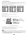
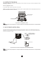
5.4. RS 232 COMMUNICATION
In order to transfer stored data to PC, RS 232 communication feature must be used.
front view
front view
2
2
3
3
5
5
9 pin female connectorto serial port on PC
9 pin male connectorto APPLIANCE MULTITESTER
Fig. 52. RS 232 communication cable
NOTE !
Use original RS 232 communication cable or connect only pins on serial DB9 connectors according to Fig. 52 to avoid
damages (pin 2, 3, 5).
32
RS232 Communication cable
Fig. 53. Connection of APPLIANCE MULTITESTER to PC
How to transfer stored data to PC
STEP 1. Connect APPLIANCE MULTITESTER to PC as shown in fig. 53 using appropriate RS 232 communication cable.
STEP 2. Open CE Link program on your PC.
STEP 3. Set baud rate (the same on PC and APPLIANCE MULTITESTER).
STEP 4. Use ↑ and ↓ keys to select one of displayed options and press Enter key
STEP 5. After pressing Enter key the selected function submenu is displayed at the bottom of menu:
5.5. SYSTEM CONFIGURATION
To reach System configuration menu the following procedure must be carried out:
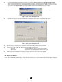
STEP 1. Switch off the instrument turning ON/OFF key to OFF position.
STEP 2. Press SET UP key and keep it pressed while switching on the instrument.
STEP 3. System configuration menu is displayed (see figure below).
Fig. 54. Basic system configuration heading
STEP 4. Use ↑ and ↓ keys to select one of displayed options and press Enter key
STEP 5. After pressing Enter key on selected function message on the bottom of heading is displayed:
DATE and TIME setup:
■
Use Sel. and ↑, ↓ keys to set day, month, year,
hour, minutes and seconds. Year must be set manually
at the beginning of each year when the time passes from
31.12 to 1.1. The warning “SYSTEM ERROR” is displayed
otherwise.
After Exit is selected the change will be confirmed and the
main system menu is offered to allow selection of other
functions or to exit to normal measuring mode.
SERIAL PORT BAUD RATE setup:
■
Use Sel. key to select appropriate baud rate from
9600, 19200 or 38400.
After exit, the new baud rate will be confirmed and basic
menu is displayed.
33
BARCODE READER BAUD RATE setup:
■
■
Use Sel. keys to select appropriate baud rate from:
2400, 4800 or 9600.
After exit, the new baud rate will be confirmed and
basic menu is displayed.
CLEAR all RECORDS:
■
Press Enter to confirm or Exit to cancel.
NOTE !
Device and bar code numbers will not be erased.
To clear individual records use Recall from memory menu
or CE link software.
CLEAR all DEVICES:
■
Press Enter to confirm or Exit to cancel clearing of
memory.
NOTE !
Before clearing, download all memorized results to PC to
avoid losing important data.
CLEAR all PROGRAMS:
■
Press Enter to confirm or Exit to cancel clearing of
memory.
NOTE !
Before clearing, download all memorized results to PC to
avoid losing important data.
LOAD DEFAULT SETTING :
Sets all adjustable test parameters to their initial values.
■
Press Enter key to confirm or Exit key to exit.
INPUT DOOR IN:
Enables or to disables DOOR IN input.
■
After selecting this option press Enter to switch
between ENABLE and DISABLE
EARTH CONTROL:
If one wishes to enable or to disable EARTH CONTROL .
■
After selecting this option press enter to switch
between ENABLE and DISABLE
NOTE !
It is advisable to disable this option only in protected IT
systems. For TN systems you should always enable it.
34
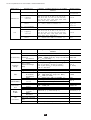
List of test parameters for each function, and their initial values:
F u n c tio n
P a ra m e te r
te s t v o lta g e
100 V - 5 kV ~
U 1= 1 k V
U 2= 3 ,7 k V
Im ax
trip p in g
c u rre n t
(0 .5 , 1 .0 , 1 .5 2 .0 , 2 .5 , 3 .0 , 3 .5 , 4 .0 ,
4 .5 , 5 .0 , 5 .5 , 6 .0 , 6 .5 , 7 .0 , 7 .5 , 8 .0 ,
8 .5 , 9 .0 , 9 .5 , 1 0 , 2 0 , 3 0 , 4 0 , 5 0 , 6 0 ,
70, 80, 90, 100, 150, 200, 250, 300,
350, 400, 450, 500) mA
2 mA
T
tim e r
1 s - 2 4 0 s w ith re s o lu tio n 1 s
T 1= 1 0 s
T 2= 1 0 s
T 3= 1 0 s
te s t v o lta g e
100 V - 5 kV ~
1 kV
2 mA
UN
( f o r I lim it a n d b u r n m o d e )
Im ax
trip p in g
c u rre n t
(0 .5 , 1 .0 , 1 .5 2 .0 , 2 .5 , 3 .0 , 3 .5 , 4 .0 ,
4 .5 , 5 .0 , 5 .5 , 6 .0 , 6 .5 , 7 .0 , 7 .5 , 8 .0 ,
8 .5 , 9 .0 , 9 .5 , 1 0 , 2 0 , 3 0 , 4 0 , 5 0 , 6 0 ,
70, 80, 90, 100, 150, 200, 250, 300,
350, 400, 450, 500) mA
T
tim e r
1 s - 9 m in 5 9 s w ith re s o lu tio n 1 s
10 s
R a n g e o f a d ju s tm e n t o r p o s s ib le
v a lu e s
100 mA, 200 mA, 10 A, 25 A∼
(1 0 - 9 9 0 ) m Ω (b y s te p s o f 1 0 m Ω )
(1 0 0 0 - 2 0 0 0 ) m Ω (b y s te p s o f 1 0 0 m Ω
o r *** Ω (n o lim it)
(1 - 5 9 ) s
5 .0 V (0 .5 0 m m 2 ), 5 .0 V (0 .7 5 m m 2 ),
3 .3 V (1 .0 m m 2 ), 2 .6 V (1 .5 m m 2 ),
1 .9 V (2 .5 m m 2 ), 1 .4 V (4 .0 m m 2 ),
1 .0 V ≥ 6 .0 m m 2
(1 - 5 9 ) s
250 V, 500 V, 1000V =
(0 .2 - 9 .9 ) M Ω (b y s te p s o f 0 .1 M Ω )
(1 0 - 2 0 0 ) M Ω (b y s te p s o f 1 M Ω )
o r *** M Ω (n o lim it)
1 s - 9 m in 5 9 s w ith re s o lu tio n 1 s
L e a k a g e , S u b s titu t (0 .0 0 - 2 0 .0 ) m A
T o u c h (0 .0 0 - 2 .0 0 ) m A
1 s - 9 m in 5 9 s w ith re s o lu tio n 1 s
In itia l v a lu e
F u n c tio n
P a ra m e te r
IN
C o n tin u ity
V o lta g e
D ro p
IS O
D IS C .
T IM E
A ll
fu n c tio n s
te s t c u rre n t
R m ax m a x.
a llo w e d
re s ista n c e
t
tim e r
∆ U m ax .m a x.
a llo w e d v o lta g e
d ro p
t
tim e r
UN
te s t v o lta g e
R m in . m in . a llo w e d
in s u la tio n
re s ista n c e
t
tim e r
Im a x
th re sh o ld
c u rre n t
t
tim e r
LEAKAG E
F u n c tio n .
te s t
In i t i a l v a l u e
UN
P R O G .H V
HV
R a n g e o f a d ju s tm e n t o r p o s s ib le
v a lu e s
S m a x th re sh o ld
pow er
t
tim e r
S y s t m e a s u rin g
s y s te m
t
tim e r
O N /O F F
R S 2 3 2 b a u d ra te
B a rc o d e r. b a u d
ra te
C o n tra st
10 A
100 mΩ
10 s
3 .3 V
(1 m m 2 )
10 s
500 V =
1 MΩ
10 s
1m A
10 s
(1 0 - 3 5 0 0 ) V A
1000 VA
1 s - 9 m in 5 9 s w ith re s o lu tio n 1 s
10 s
e xte rn a l (1 s ), in te rn a l (5 s )
e xte rn a l (1 s )
O N or O FF
ON
9600, 19200, 38400
38400
2400, 4800, 9600
9600
(0 - 1 0 0 ) % (b y s te p s o f 2 % )
50 %
35
5.6. CONTRAST OF THE DISPLAY
Where there is insufficient readability of the display (display too dark or intensity of messages too weak), the appropriate contrast
of the display should be set.
How to set appropriate contrast
It is possible to adjust contrast in all positions of main switch.
STEP 1. Press SET key together with F3 to make the display darker or together with F2 to make the display brighter (keep the keys
pressed until the desired contrast is achieved)
Keep pressed together to
make display darkest
Keep pressed together to
make display brightest
Fig. 55. How to set appropriate contrast
NOTE !
The selected contrast may change due to a change in temperature of the display (instrument heat or changed ambient
temperature).
5.7. USE OF REMOTE CONTROL PEDAL
The pedal is intended to start and stop the measurement (in each function) as well as to save displayed results by foot. It is
advisable to use the pedal when both hands are occupied with test probes, or when tests are to be carried out away from the
instrument using longer test cables.
START/STOP
IDENT
3
2
GND
1
4
5
Instrument connector
(female) type MAB 6100
DIN 45322 (front view)
SAVE
1
3
Pedal switches
SAVE
2
START/
STOP
front view
5
Fig. 56. Connection of remote control pedal to APPLIANCE MULTITESTER
NOTE !
The selected contrast may change due to a change in temperature of the display (instrument heat or changed ambient
temperature).
36
How to operate REMOTE CONTROL pedal
START/STOP function on the pedal is exactly the same as on front panel of the instrument when the pedal is not connected.
SAVE function on the pedal is automatic, so a double press to SAVE pedal is required to save displayed result to the next location
of set device number. The device number must be set in advance. If you press SAVE more than twice, the instrument will throw into
Recall function and you cannot exit it by using REMOTE PEDAL. You can exit this function only by pressing front panel key on the
instrument.
The following procedure is to be used:
STEP 1. Connect REMOTE CONTROL pedal to the instrument as it is shown in fig.56 and carry out the measurement by pressing
START/STOP pedal.
STEP 2. Save the first result to desired memory location (memory number and device number) using front panel keys, see the
instructions in chapter 5.2.
STEP 3. Carry out the next test using START/STOP pedal.
STEP 4. Save the result by pressing SAVE pedal twice.
STEP 5. Proceed with the measurements.
Technical specifications of the pedal:
■
Cable length
10 m
■
Commands
START/STOP, SAVE
■
Casing
metal
■
Weight
2 kg
■
Size (W×H×D) (300 × 55 × 175) mm
5.8. USE OF WARNING LAMP
The lamp is intended to inform the user if dangerous voltages are present when WITHSTANDING tests are carried out (HV and
PROG.HV position).
Meaning of each lamp:
Red (TEST) lamp on means that dangerous voltage is present at WITHSTANDING test terminals. Take care when
using test pistols!
Green (READY) lamp on means that the instrument is ready for the next measurement, dangerous voltage is not
present at WITHSTANDING test terminals.
READY
-
TEST
12V DC
F6
+
2
1
34
5
Instrument connector
(female) type MAB 5100
DIN 41524 (front view)
and internal instrument
circuitry
front view
Fig. 57. Connection of warning lamp to APPLIANCE MULTITESTER
Technical specifications of the WARNING LAMP:
■
Cable length
1m
■
Lamp bulbs
(12 - 15) V / 4 W
■
Casing
plastic
■
Weight
0.3 kg
■
Size (W×H×D)
(200 × 95 × 110) mm
NOTE !
If no lamp lights when rotary switch is in HV position, stop the measurements immediately and check the WARNING LAMP
connection and light bulbs.
37
5.9. USE OF BARCODE READER
Fig. 58. Connection of barcode reader to APPLIANCE MULTITESTER
Use a barcode reader that includes RS232 communication with DB9 (male) connector. Select baud rate for barcode reader (see
chapter 5.5 System configuration)
To add a barcode number to the currently enabled device use serial barcode reader. This operation is allowed in all measuring
positions before or after the measurement.
After this action in memory menu, the bar code number is displayed together with device number and number of saved results.
5.10. USE OF EXT/DOOR INPUT
Specification of EXT. / DOOR IN signals:
Pin 2: Pass / Fail
Pin 3: External input
Pin 4: Next test
Pin 5: Door in
Pin 6: Gnd
(digital
(digital
(digital
(digital
output)
input)
output)
input)
5.10.1. DOOR INPUT
If the DOOR IN input is enabled (see chapter 5.5 – System configuration), tests in PROG. HV and HV position will not be started
until the door is not open. See figure bellow to connect DOOR IN signal to APPLIANCE MULTITESTER.
front view
READY
5
6
9 pin male connectorto APPLIANCE MULTITESTER
EXT / DOOR IN
Fig. 59. Connection of DOOR IN signal to APPLIANCE MULTITESTER
5.10.2 EXTERNAL INPUT
EXT port is intended to
- show the result (PASS / FAIL) of measurement,
- give information during sequenced measurements (for AUTOTEST sequence),
- allow external control of AUTOTEST sequence execution.
Fig. 60. Signals of EXT port
38
PASS / FAIL:
In autotest and individual measurements the status of measurement (PASS / FAIL) is given on pin 2 of EXT / DOOR IN connector.
If the measurement result is inside the range of limit then pin 2 is HI level. If the measurement is out of limit range then pin 2 is LO
level.
pin 2 – HI level:
- the next program step of the autotest will be executed
pin 2 – LO level:
- press START key to restart measurement
- press Skip key - program will continue with the next step
- press Exit key to stop program execution and return to
AUTOTEST menu
External:
Pin 3 of DOOR IN input is supported by Autotest program command ‘ Wait for external input’.
Generally the user can define four different kind of pause between too sequent measurements.
1.
Predefined time pause - common equal pause between measurements (it can be set from 1 s to 5 s in sequence editor:
Program name / Pause).
2.
Time pause – it has to be inserted as a ‘Pause’ command as the last command in the *.SQC program. In this case the total
pause between two sequent measurements is predefined time pause + Time of ‘Pause’ command.
3.
Message - it has to be inserted as a ‘Message’ command in the*.SQC program. The instrument waits for the user reaction
(connect test leads to tested object and press START).
4.
Wait for external input – this command waits for change from HI to LO on pin 3 of DOOR / IN input (see figure below.)
Fig. 61. Wait for external input diagram
Application example – unpredictable pause time for the same action (manual action is part of preparation for another measurement).
Next test:
Pin 4 indicates the end of execution of each measurement (change from LO to HI). Immediately after the start of another
measurement it changes from HI to LO state.
Fig. 62. Next test signal diagram
39
6. MAINTENANCE
6.1. METROLOGICAL CHECK
It is essential that all measurement instruments are regularly calibrated.
We recommend an annual calibration to be carried out.
6.2. SERVICE
Repairs under or out of guarantee: Please return the products to your distributor.
6.3. CLEANING
To clean the surface of teh instrument, use a soft cloth slightly moistened with soapy water or alcohol. Then leave the instrument
to dry totally before use.
■
Do not use liquids based on petrol or hydrocarbons!
■
Do not spill cleaning liquid over the instrument! Always moisten the cloth and then clean the instrument!
6.4. REPLACING THE FUSES (BY PROPERLY TRAINED SERVICE PERSONNEL ONLY!)
In the case of instrument malfunction, send the instrument to an appropriate service center for all four fuses to be checked.
See the purpose of each fuse in paragraph 3.9.
Use original fuses only as declared in paragraph 3.9!
Disconnect all test cables and mains cord before opening the instrument.
Hazardous voltage may be present inside the instrument.
Properly trained service personnel only should carry out operation.
Position of fuses inside instrument:
F5
F6
T 32A (10.3x38) mm 400V~ (inside instrument on front panel, protect continuity circuitry)
F 500mA / 250V (on main PCB board, protect warning lamps outputs)
6.5. REPLACING THE BATTERY (BY PROPERLY TRAINED SERVICE PERSONNEL ONLY!)
This product contains a lithium battery the user must not remove.
6.6. REPAIRS
Repairs under or out of guarantee.
Please return the product to your distributor.
40
7. PC SOFTWARE - CE LINK
7.1. INSTALLING CE LINK
■
■
■
■
■
■
CE Link software is 32-bit application for Windows platforms.
Before installing CE Link it is recommended to close all running programs on your PC. After installation is complete there is
no need to restart computer
Insert installation disc in your computer and run SETUP.EXE.
Standard Install Shield Wizard will guide you through installing process.
Program will be installed in directory ‘’C:\Program Files\CE Link’’ or in directory you select.
After installation is done you are able to run CE Link.exe from Start menu.
WARNING:
This program is protected by copyright law and international treaties.
Unauthorized reproduction or distribution of this program, or any portion of it, may result in severe civil and criminal penalties, and
will be prosecuted to the maximum possible under law.
7.2. INTRODUCTION NOTES
APPLIANCE MULTITESTER has a powerful Windows platform support tool – “CE Link”. It is used for downloading of recorded
data, additional analyzing of recorded data, for creating measurement sequences, for creating report documentation, and more.
Basic screen is start point for all actions.
Fig. 63. Basic screen
41
Download data:
Port settings:
Opens window for
downloading or auto downloading data from
Appliance MultiTester to
PC.
Opens window for port and
baud rate settings.
Shortcut key:
Alt S + P
Shortcut key:
Alt F + D
Open data file:
Help:
Opens window for analyzing recorded data file.
Opens help window.
Shortcut key:
Alt F + O
Shortcut key: Alt H
Header programing:
Exit:
W ith this tool user can
define header for printed
documents.
Exits CE Link.
Shortcut key:
Alt F + E
Shortcut key:
Alt F + H
Sequence editor:
Tool for programing
AUTOTEST sequences.
Shortcut key:
Alt F + S
Table. 1. Fast access buttons
7.3. DOWNLOAD DATA
Before starting ‘’Download data’’ window it is necessary to:
■
■
Connect APPLIANCE MULTITESTER to PC according to figure 53 (chapter 5.4. RS 232 Communication) using
appropriate RS 232 communication cable (Fig. 52).
heck et baud rate (same value must be set in CE Link and APPLIANCE MULTITESTER is necessary)
Set baud rate in CE Link software by using Port settings window.
42
Fig. 64. Port settings window
■
■
■
Check baud rate on APPLIANCE MULTITESTER by using SET key (see SERIAL PORT BAUD RATE setup in SYTEM
CONFIGURATION in chapter 5.5)
Prepare APPLIANCE MULTITESTER for communication by pressing RS232 key (instrument will go in communication
mode).
Choose Download \ Standard download data option in main CE Link window
Fig. 65. Standard download mode
■
After message “Downloading in progress...” is displayed and if the downloading is done successfully, the user will
define name for this data file and it will be saved on disc in desired folder by pressing Save key.
Fig. 66. Downloading data windows
43
■
For auto download from instrument (instrument must be in the Autotest mode) choose AutoReceive download
option. In this mode PC waits to receive record from the instrument. Instrument sends record to the PC at the end of
each sequence procedure. After downloading the sequence will be executed again. For details of sequence creating
see chapter 7.6 Sequence editor (in program definition window AutoSend option has to be enabled)
Fig. 67. Auto receive download mode
■
After the file name for storing downloaded data is defined the ‘Auto receive mode’ window will appear.
Fig. 68. Auto receive download mode
■
■
■
Before starting of the autotest you should press Start button in the Auto receive mode window.
There is a counter for the number of received records since Start pressed.
Auto receive mode enables two different ways for printing received results:
- Auto print
( automatically prints the results after each reception)
- Manual print
(print results after Print button in the Auto receive mode
is pressed)
At the end of auto download you should press Stop button in the Auto receive mode window.
7.4. OPEN DATA FILE
To open one of downloaded data files press “Open data file” button in basic screen. Window for file selection will be displayed.
44
Fig. 69. Selecting file “example2. DTA”
After selecting the desired data file and pressing Open downloaded data will be displayed in the table form. Table
organization is same as in instruments internal memory; from Device 1 to last Device (max 255) with saved results, - see
chapter 5.2. Memorizing of results.
Fig. 70. Data file window
In the table all failed measurements will be marked by red color. By using search button (see table 2) the user can easily jump from
one to another failed measurement.
For table editing (for example if a measurement result is saved during measuring under wrong device index by mistake) standard
utilities are available, such as copy, cut, paste, delete etc. All those operations affect selected row.
After table editing device and memory numbers can be rearranged from top to bottom by pressing Rearrange button.
45
New / Edit Device:
Copies selected row.
Adds description, edits
dev ice or barcode num ber
or creates new dev ice.
Shortcut key:
Ctrl+C, Alt E + C
Shortcut key:
Alt E + N
Copy:
Insert / Edit comment:
Cut:
Cuts selected row.
Inserts row with com m ent or
edit existed com m ent.
Shortcut key:
Ctrl+X, Alt E + U
Shortcut key:
Alt E + O
Paste:
Save table:
Paste last cut or copied row.
To sav e edited table.
Shortcut key:
Ctrl+V, Alt E + P
Shortcut key:
Alt F+S
Delete:
Export to clipboard:
Deletes selected row (after
delete paste is not av ailable).
Exports selected rows on
clipboard.
Shortcut key:
Delete, Alt E + S
Shortcut key:
Alt E
Mark / Unmark row:
Print:
M arks or unm arks im portant
row.
Prints open data fille.
Shortcut key:
Alt E + D
Shortcut key:
Alt F + P
ReArrange numbers:
Main window:
Rearranges from top to
bottom dev ice and m em ory
num bers (often used after
editing table).
Jum ps to m ain window
without closing.
Shortcut key:
Alt F + M
Shortcut key:
Alt E + R
Search:
Close:
Jum ps on next row with error
v alue.
Closes window and return to
m ain window.
Shortcut key:
Alt E + S
Shortcut key:
Alt F + C
Table. 2. Fast access buttons
The user can insert a new row with comment or edit existing comments (Insert / Edit comment button). To export measurement
to other programs, the user can use Export to clipboard option (Copy / Paste commands do not work with Windows clipboard).
Note: only selected rows will be exported.
46
7.5. PRINTING DOCUMENTS
7.5.1 PRINTING SELECTED ROWS
Selected rows can be printed following this steps:
1. Select rows to be printed (use Shift + left mouse button for selecting subsequent records to record or Ctrl + left mouse button for
selecting one row by one).
2. Choose Window for printing option in File men.
3. To create header select Define header in File menu.
4. Choose Print form Print menu.
Header options
■
■
■
■
■
■
define header height,
include bitmap file (user logo - in our example windows
clouds.bmp),
underline header,
write header text (first line above bitmap, other five under), for
every line set appropriate font or insert commands like system
date, time, serial number, current page, total pages,
load or save created header,
preview created document.
Fig. 71. Creating Header for printed documents
47
Our example will create header bellow.
Fig. 72. PRINT preview
7.5.2 PRINT SEPARATELY
Print separately function prints each measured device results to its own document. It is intended to print separate reports for
each tested object (production line testing).
48
7.6. HEADER PROGRAMMING
Fig. 73. Header programming window
This window represents info window for your instrument (called header). To see instrument header the instrument has to be
connected to PC.
User can change “User string” (max 48 characters), send system time (time and date set on the PC).
It is possible to change User string only in this way. Instrument time and date or baud rates can be edited directly on
instrument without using software (see instruction in chapter 5.5. System configuration).
49
7.7. SEQUENCE EDITOR
Basic point of Sequence editor is displayed in chapter 4.10. AUTOTEST. The user will use Sequence editor to create desired
sequences or to edit existing sequence on the instrument. Max. number of steps in one sequence is 50, including
programmed pause, messages, barcode reader sequence and sound signals. Max. number depends on combination of
included function in current example.
Fig. 74. Sequence editor window
Two main parts of Sequence editor are Command table and Program table. Command table contains all commands that can be
executed on Appliance Multitester.
User crates his sequence by selecting command one by one, and assigning them into program table using Get command key
or by double clicking the desired command. For all selected commands limit values have to be set by using Edit parameters
key.
50
Voltage drop Parameter window
Continuity Current Parameter window
High Voltage Parameter window
Programed High Voltage Parameter window
Insulation Parameter window
Sound Parameter window
51
Pause Parameter window
Leakage Current Parameter window
Message Parameter window
Fig. 75. Parameter windows
To set program name in Command table select Program name.
In this dialog box user can also enable:
- pause (0 s – 5 s) between each test of the sequent,
- saving of measurement results,
- increment device number for successive sequence results,
- auto send each sequence results to PC (suitable for automate of production lines).
- auto repeat (autotest sequence is circularly repeated after defined Pause 0-5 sec).
Fig. 76. Program name – definition window
Created sequence can be sent to Appliance Multitester, and saved to disc with extension SQC.
52
List of instrument
programs:
Clear row data:
Clears only data, not whole
row.
Reads, delete and sends
sequence to instrument.
Shortcut key:
Alt S + P
Shortcut key:
Alt F + D
Get command:
Insert empty row:
Copies selected command
from command table to
program table.
Inserts an empty row at
selected row (for a new
command).
Shortcut key:
Alt F + O
Shortcut key:
Alt H
Edit parameters:
Set limits and other
parameters for selected
type of measurement.
Shortcut key:
Alt F + H
Table. 3. Fast access buttons
53
8. TO ORDER
■
■
C.A 6160 APPLIANCE MULTITESTER (GB) ------------------------------------------------------------------------------- P01145801A
C.A 6160 APPLIANCE MULTITESTER (EURO) --------------------------------------------------------------------------- P01145801
Standard supply :
- 1 power supply lead (Euro or GB)
- 2 dielectric test guns (probes) with cable 2m
- 2 insulation test leads, 3m (1 red, 1 black)
- 4 crocodile clips (2 red, 2 black)
- 2 test probes (1 red, 1 black)
- 4 continuity test leads, 2.5m (2 red, 2 black)
- 1 discharge time cable (EURO or GB)
- 1 bag for the accessories
- 5 user’s manuals (5 languages)
■
ACCESSORIES
- PC software + communication cable DB9F-DB9F -------------------------------------------------------------------------------- P01101996
- Remote control probe --------------------------------------------------------------------------------------------------------------------- P01101916
- Warning lamps (green / red) ------------------------------------------------------------------------------------------------------------ P01101917
- 2 dielectric test guns with cable 6m --------------------------------------------------------------------------------------------------- P01101918
- 1 adapter DB9M/DB9F -------------------------------------------------------------------------------------------------------------------- P01101941
■
SPARE PARTS
- 1 bag for accessories --------------------------------------------------------------------------------------------------------------------- P01298061A
- 2 dielectric test guns (probes) with cable 2m --------------------------------------------------------------------------------------- P01101919
- 2 insulation test leads, 3m (1 red, 1 black) ------------------------------------------------------------------------------------------ P01295097
- 2 crocodile clips (1 red, 1 black) ------------------------------------------------------------------------------------------------------- P01295457Z
- 2 test probes (1 red, 1 black) ------------------------------------------------------------------------------------------------------------ P01295458Z
- 2 continuity test leads, 2.5m (1 red, 1 black) ---------------------------------------------------------------------------------------- P01295236
- 1 discharge time cable (EURO) -------------------------------------------------------------------------------------------------------- P01295141
- 1 discharge time cable (GB) ------------------------------------------------------------------------------------------------------------- P01295142
- 1 power supply lead (EURO) ----------------------------------------------------------------------------------------------------------- P01295234
- 1 power supply lead (GB) ---------------------------------------------------------------------------------------------------------------- P01295235
- 1 RS232 communication cable DB9F-DB9F --------------------------------------------------------------------------------------- P01295172
- 10 fuses 16A-250V 6x32T --------------------------------------------------------------------------------------------------------------- P01297086
- 10 fuses 2.5A-250V 5x20T -------------------------------------------------------------------------------------------------------------- P01297085
54
06 - 2014
Code 691030A02- Ed. 7
DEUTSCHLAND - Chauvin Arnoux GmbH
Straßburger Str. 34 - 77694 Kehl / Rhein
Tel: (07851) 99 26-0 - Fax: (07851) 99 26-60
SCHWEIZ - Chauvin Arnoux AG
Moosacherstrasse 15 - 8804 AU / ZH
Tel: +41 44 727 75 55 - Fax: +41 44 727 75 56
ESPAÑA - Chauvin Arnoux Ibérica SA
C/ Roger de Flor N° 293, Planta 1
08025 Barcelona
Tel: +34 902 20 22 26 - Fax: +34 93 459 14 43
UNITED KINGDOM - Chauvin Arnoux Ltd
Unit1 Nelson Court - Flagship Square- Shaw Cross Business Park
DEWSBURY - West Yorkshire - WF12 7TH
Tel: +44 1924 460 494 - Fax: +44 1924 455 328
ITALIA - Amra SpA
Via Sant’Ambrogio, 23 - 20846 MACHERIO (MB)
Tel: +39 039 245 75 45 - Fax: +39 039 481 561
MIDDLE EAST - Chauvin Arnoux Middle East
P.O. BOX 60-154 - 1241 2020 JAL EL DIB (Beirut) - LEBANON
Tel: +961 1 890 425 - Fax: +961 1 890 424
ÖSTERREICH - Chauvin Arnoux Ges.m.b.H
Slamastrasse 29/2/4- 1230 Wien
Tel:+43 1 61 61 9 61 - Fax: +43 1 61 61 961-61
CHINA - Shanghai Pu-Jiang - Enerdis Instruments Co. Ltd
3 F, 3 rd Building - N° 381 Xiang De Road - 200081 SHANGHAI
Tel: +86 21 65 21 51 96 - Fax: +86 21 65 21 61 07
SCANDINAVIA - CA Mätsystem AB
Box 4501 - SE 18304 TÄBY
Tel: +46 8 50 52 68 00 - Fax: +46 8 50 52 68 10
USA - Chauvin Arnoux Inc - d.b.a AEMC Instruments
200 Foxborough Blvd. - Foxborough - MA 02035
Tel: +1 (508) 698-2115 - Fax: +1 (508) 698-2118
http://www.chauvin-arnoux.com
190, rue Championnet - 75876 PARIS Cedex 18 - FRANCE
Tél. : +33 1 44 85 44 85 - Fax : +33 1 46 27 73 89 - [email protected]
Export : Tél. : +33 1 44 85 44 86 - Fax : +33 1 46 27 95 59 - [email protected]
55