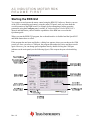
1
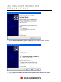
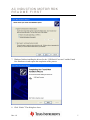
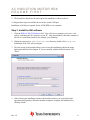
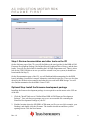
AC INDUCTION MOTOR RDK README FIRST Stellaris® AC Induction Motor RDK Stellaris reference design kits (RDKs) from Texas Instruments accelerate product development by providing ready-to-run hardware, a typical motor, and comprehensive documentation that includes hardware design files. Using the AC induction motor (ACIM) RDK designers without prior motor control experience can successfully implement a sophisticated motor-control system. Installing and Starting the AC Induction Motor This section describes how to connect and run the motor and also how to connect the tachometer cable. In addition, important safety information is included to prevent damage to the motor and injury to anyone working with the motor. Safety Information This RDK operates from AC line voltage. Improper use or application carries electric shock, fire, and other risks that may result in serious injury or death. Please read and follow these safety notices: • This documentation and kit must only be used by people with training and experience in working with voltage potentials up to 230 V. • The control board has both high-voltage potential and safety low-voltage sections. • Do not connect high-voltage potential circuits to safety low-voltage circuits or to groundreferenced equipment such as computers or test equipment. • After power is removed, high voltages remain until the bus capacitors discharge. Wait at least one minute after removing power before working with high-voltage circuitry. • Use caution when using the on-board controls to adjust motor speed etc. High-voltage circuits are in close proximity. • Never perform work on the control board, motor or, wiring while power is applied. Always wear eye protection and use care when operating the motor. In addition to safety risks, other factors that may damage the control hardware, the motor, and its load include improper configuration, wiring, or software. Minimize the risk of damage by following the information in the AC Induction Motor RDK User’s Manual. Kit Contents The RDK includes the following items: • • Motor control board, complete with heat-sink plate Selni AC motor, three-phase, 0-190 V, 0-340 Hz, with power cable Rev. 1.5 1 AC INDUCTION MOTOR RDK README FIRST • • • • 6-foot IEC power cord (North American) 3-foot USB cable, mini-B to USB-A 3-foot tachometer cable assembly CD-ROM containing AC Induction Motor RDK User’s Manual, RDK GUI, source code, and data sheets Step 1: Connecting and Running the Motor 1. Connect the motor power cable to the control board by inserting the four-position plug into the MOTOR socket on the control board. The connectors are polarized. 2. Select 115-V or 230-V input voltage. The control board has inputs for 115-V and 230-V AC. The factory default setting is 230-V. To operate the control board from 115-V, move the two-position plug to the socket labeled 115-V Line. CAUTION: You can damage the power-supply control by connecting to a 230-V power source when it is configured for a 115-V power source. Rev. 1.5 2 AC INDUCTION MOTOR RDK README FIRST 3. Apply power by connecting the IEC power cord to the line filter module. If the included cable is not compatible with local AC outlets, you can use any standard equipment cable (such as a desktop computer power cable). When power is applied the green Power LED is ON. As the DC bus charges, the Fault Status LED flashes red momentarily; this is normal operation and avoids excessively high start-up currents. 4. Control the motor by pressing the Mode switch to start and stop the motor or change motor direction. The first press starts the motor, the second press stops the motor, the third press starts the motor in the opposite direction, and the fourth press stops the motor. Use the Speed POT (potentiometer) to adjust motor speed between 60 and 340 Hz. Step 2: Installing the Tachometer Cable The tachometer cable allows the RDK control board to monitor and actively control actual motor speed. For this step, you need a small, flat-head screwdriver. 1. Connect the tachometer cable’s spade connectors to the motor terminal block (terminals 4 and 5). The polarity is not important. Rev. 1.5 3 AC INDUCTION MOTOR RDK README FIRST 2. Connect the bare wires to the RDK control board screw terminals. The black wire connects to 0-V. The red wire connects to ENA. CAUTION: Ensure that the tachometer cable is connected only to motor terminals 4 and 5. Terminals 1, 2 and 3 are only for motor-power wiring. Installing and Using the RDK GUI Software Using the RDK GUI provides a greater level of control than the on-board interface. Through the RDK GUI, you can set specific values for speed, acceleration, and deceleration, as well as a number of other parameters that further tune the operation of the motor. The RDK GUI program communicates with the RDK board using a virtual serial port over a USB cable. Features • • • Real-time display of control board parameters Control of motor speed and direction Over 40 configuration parameters that allow operation customization for specific applications Software Installation Requirements • • • Completion of the steps for “Installing and Starting the AC Induction Motor” from page 1 of this Quickstart document. A computer with a USB interface, running Microsoft® Windows 98, 2000, XP, or 2003 The ACIM RDK documentation and software CD-ROM Rev. 1.5 4 AC INDUCTION MOTOR RDK README FIRST Step 1: Insert CD 1. Insert the RDK Documentation and Software CD into the CD-ROM drive of your computer. If Autoplay is enabled on your PC, the index.htm file automatically opens in your default web browser. If not, use Windows Explorer or other browser to open the index.htm file manually. 2. From the CD menu, select the Software button to open a page from which you will be able to download the GUI software and RDK firmware. To install the GUI software and RDK firmware, you will perform the following steps: • • • • Install the USB serial and virtual COM port drivers Install the GUI software Review documentation and other tools on the CD Install the firmware development package (optional, not required to run the motor or GUI out of the box) Step 2: Install the USB serial and virtual COM port drivers You must install the USB driver software before you can use the GUI. This includes the drivers for the two parts of the included composite USB device, which are the USB serial converter and the Virtual COM port. To do this: 1. Connect the mini-b (smaller) end of the USB cable to the connector labeled USB on the RDK 2. Connect the other end (Type A) to a free USB port on your host computer. 3. When you plug in the EVB for the first time, Windows starts the Found New Hardware Wizard and asks if Windows can connect to Windows Update to search for software. 4. Select No, not this time and then click “Next.” Rev. 1.5 5 AC INDUCTION MOTOR RDK README FIRST 5. Select Install from a list or specific location and click Next. If needed, insert the documentation and software CD into the CD-ROM drive. 6. Select Search for the best driver in these locations and Search removable media. Click Next. Rev. 1.5 6 AC INDUCTION MOTOR RDK README FIRST 7. Windows finishes installing the drivers for the “USB Serial Converter” and the Found New Hardware wizard reports the completion of the process. 8. Click “Finish.” The dialog box closes. Rev. 1.5 7 AC INDUCTION MOTOR RDK README FIRST 9. The Found New Hardware Wizard reopens for installation of the next driver. 10. Repeat these steps to install the driver for the virtual COM port. Installation of all drivers required for the ACIM RDK is now complete. Step 3: Install the GUI software 1. Click the RDK-ACIM GUI Software link. Your web browser prompts you to save a zip archive containing the GUI software to your PC. Once downloaded, extract the contents of this file to a convenient location (for example, your Desktop). 2. Within the extracted SW-RDK-ACIM-gui-nnn directory, double-click setup.exe. Installation of the GUI software begins. 3. The first screen of the installer allows you to select the installation path for the target application and Run-Time Engine. If you are satisfied with the default location, click “Next”. 4. After selecting the installation location, the installer assumes you accept the license agreement and continues. When the installer completes, complete the installation by clicking “Finish.” Rev. 1.5 8 AC INDUCTION MOTOR RDK README FIRST Step 4: Review documentation and other tools on the CD On the Software page of the CD, you will find links to the user's guides for the RDK-ACIM Firmware Development Package, the StellarisWare® Peripheral Driver Library, and the boot loader. You will also find a link for installing the LM Flash Programmer tool. There is also a link for the FTDI USB driver in case you need to reinstall it on your system (it should have been installed in Step 2). On the Documentation page of the CD, you will find detailed documentation for the RDK board, including a board user's manual, schematics, and other design files. There are also data sheets for the Stellaris microcontroller and other devices used in the RDK design. You will also find documentation for the ARM® Cortex™-M3. Optional Step: Install the firmware development package Installing the firmware development package is not required to run the motor or the GUI out of the box. 1. Click the "Install" link next to "StellarisWare RDK-ACIM Firmware Development Package". Your web browser prompts you to save an executable file containing the Firmware Development Package to your PC. 2. Find the location where the SW-RDK-ACIM-nnnn.exe file was saved (for example, your Desktop), and double-click the file name. The installer should run and show you the opening screen. Click the Next button. Rev. 1.5 9 AC INDUCTION MOTOR RDK README FIRST 3. Read the license agreement. Select the button that says "I accept ..." and then click the Next button. Rev. 1.5 10 AC INDUCTION MOTOR RDK README FIRST 4. The installation path for the RDK firmware package displays. You can use the suggested path or change it. When you are satisfied with the location, click the Next button. 5. You are now ready to install the Firmware Development Package. Click the Next button to begin the installation. Rev. 1.5 11 AC INDUCTION MOTOR RDK README FIRST 6. You will be shown a progress screen as the software is installed. 7. When the installation is finished, click the Finish button to close the installer. The RDK firmware development package is now installed on your system. Rev. 1.5 12 AC INDUCTION MOTOR RDK README FIRST Starting the RDK GUI You connect to and operate the motor control using the RDK GUI software. Restrict your use of the GUI to monitoring and control, using the main GUI panel, until you learn about the overall operation of the RDK board. For example, before attempting to adjust operating parameters using the Configure panel, read the AC Induction Motor Control RDK User’s Manual and familiarize yourself with the capabilities of the RDK not covered in this Quickstart guide. When you start the RDK GUI program, the on-board interface is disabled and the Speed POT and Mode button have no effect. If the program has not been used before, a dialog box appears where you can choose the COM port to use. Once you select a COM port, the program remembers the choice and does not ask again. However, you can change port assignment later by double-clicking the COM port indicator on the main panel (see the following figure). This reopens the port selection dialog box. Rev. 1.5 13 AC INDUCTION MOTOR RDK README FIRST Basic ACIM RDK GUI Operation Some of the tasks you can perform using the ACIM RDK main GUI window include: Task Action Start the motor. Click Run. Stop the motor. Click Stop. Change motor direction. Select Reverse Direction. Set motor speed (in Hz). Reconnect to RDK board. In the Frequency (Hz) pane, enter a new Target value between 60 and 340. In the Speed (rpm) pane, enter a new Target value between 1800 and 20400. Double-click Target button. Change COM port. Double-click Port Indicator button. Clear a fault indicator. In the Fault Indicator bar, double-click the name of the indicator you want cleared. Set motor speed (in RPM) For details on the use of other window controls, see the ACIM RDK User’s Manual. Troubleshooting In addition to the troubleshooting information in the ACIM RDK User’s Manual, the following provides workarounds to common problems. Power LED is not ON when power is applied Confirm that the power connector to the printed circuit board (PCB) is properly inserted in the correct location (115-V or 230-V). Check the fuse. See the ACIM RDK User’s Manual for instructions on fuse replacement. Ensure any circuits connected to the 5-V terminal do not exceed 40 mA Unable to connect to control using RDK GUI over USB Check virtual COM port assignment using the Windows Device Manager. Windows may periodically assign a different COM port number when the ACIM RDK is connected. Remove any other virtual COM port devices from the PC Reset the motor control board by pressing the RESET button. Do this carefully as high voltages are nearby. Rev. 1.5 14 AC INDUCTION MOTOR RDK README FIRST Conclusion You have now successfully operated a three-phase AC induction motor using the reference design kit in both stand-alone and RDK GUI-controlled modes. Be sure to read the ACIM RDK User’s Manual, which explains each of the parameters accessible using the RDK GUI. The ACIM RDK User’s Manual provides information on how you can adapt the software and hardware for a specific application. References The following references are included on the AC Induction Motor RDK documentation CD and are also available for download at www.luminarymicro.com: Stellaris ACIM Control RDK User’s Manual, publication number RDK-ACIM Stellaris AC Induction Motor RDK Software Reference Manual, publication number RDK-ACIM-srm Copyright © 2007–2009 Texas Instruments, Inc. All rights reserved. Stellaris and StellarisWare are registered trademarks of Texas Instruments. ARM and Thumb are registered trademarks, and Cortex is a trademark of ARM Limited. Other names and brands may be claimed as the property of others. Texas Instruments 108 Wild Basin Rd., Suite 350 Austin, TX 78746 Main: +1-512-279-8800 Fax: +1-512-279-8879 http://www.luminarymicro.com Rev. 1.5 12/8/2009 IMPORTANT NOTICE Texas Instruments Incorporated and its subsidiaries (TI) reserve the right to make corrections, modifications, enhancements, improvements, and other changes to its products and services at any time and to discontinue any product or service without notice. Customers should obtain the latest relevant information before placing orders and should verify that such information is current and complete. All products are sold subject to TI’s terms and conditions of sale supplied at the time of order acknowledgment. TI warrants performance of its hardware products to the specifications applicable at the time of sale in accordance with TI’s standard warranty. Testing and other quality control techniques are used to the extent TI deems necessary to support this warranty. Except where mandated by government requirements, testing of all parameters of each product is not necessarily performed. TI assumes no liability for applications assistance or customer product design. Customers are responsible for their products and applications using TI components. To minimize the risks associated with customer products and applications, customers should provide adequate design and operating safeguards. TI does not warrant or represent that any license, either express or implied, is granted under any TI patent right, copyright, mask work right, or other TI intellectual property right relating to any combination, machine, or process in which TI products or services are used. Information published by TI regarding third-party products or services does not constitute a license from TI to use such products or services or a warranty or endorsement thereof. Use of such information may require a license from a third party under the patents or other intellectual property of the third party, or a license from TI under the patents or other intellectual property of TI. Reproduction of TI information in TI data books or data sheets is permissible only if reproduction is without alteration and is accompanied by all associated warranties, conditions, limitations, and notices. Reproduction of this information with alteration is an unfair and deceptive business practice. TI is not responsible or liable for such altered documentation. Information of third parties may be subject to additional restrictions. Resale of TI products or services with statements different from or beyond the parameters stated by TI for that product or service voids all express and any implied warranties for the associated TI product or service and is an unfair and deceptive business practice. TI is not responsible or liable for any such statements. TI products are not authorized for use in safety-critical applications (such as life support) where a failure of the TI product would reasonably be expected to cause severe personal injury or death, unless officers of the parties have executed an agreement specifically governing such use. Buyers represent that they have all necessary expertise in the safety and regulatory ramifications of their applications, and acknowledge and agree that they are solely responsible for all legal, regulatory and safety-related requirements concerning their products and any use of TI products in such safety-critical applications, notwithstanding any applications-related information or support that may be provided by TI. Further, Buyers must fully indemnify TI and its representatives against any damages arising out of the use of TI products in such safety-critical applications. TI products are neither designed nor intended for use in military/aerospace applications or environments unless the TI products are specifically designated by TI as military-grade or "enhanced plastic." Only products designated by TI as military-grade meet military specifications. Buyers acknowledge and agree that any such use of TI products which TI has not designated as military-grade is solely at the Buyer's risk, and that they are solely responsible for compliance with all legal and regulatory requirements in connection with such use. TI products are neither designed nor intended for use in automotive applications or environments unless the specific TI products are designated by TI as compliant with ISO/TS 16949 requirements. Buyers acknowledge and agree that, if they use any non-designated products in automotive applications, TI will not be responsible for any failure to meet such requirements. Following are URLs where you can obtain information on other Texas Instruments products and application solutions: Products Amplifiers Data Converters DLP® Products DSP Clocks and Timers Interface Logic Power Mgmt Microcontrollers RFID RF/IF and ZigBee® Solutions amplifier.ti.com dataconverter.ti.com www.dlp.com dsp.ti.com www.ti.com/clocks interface.ti.com logic.ti.com power.ti.com microcontroller.ti.com www.ti-rfid.com www.ti.com/lprf Applications Audio Automotive Broadband Digital Control Medical Military Optical Networking Security Telephony Video & Imaging Wireless www.ti.com/audio www.ti.com/automotive www.ti.com/broadband www.ti.com/digitalcontrol www.ti.com/medical www.ti.com/military www.ti.com/opticalnetwork www.ti.com/security www.ti.com/telephony www.ti.com/video www.ti.com/wireless Mailing Address: Texas Instruments, Post Office Box 655303, Dallas, Texas 75265 Copyright © 2009, Texas Instruments Incorporated