1
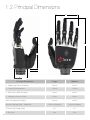
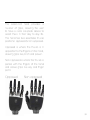
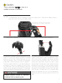
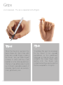
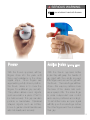
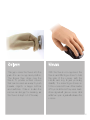
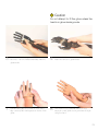
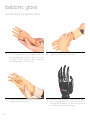
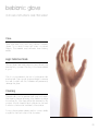
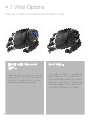
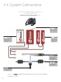
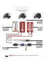
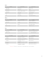
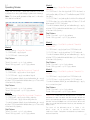
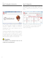
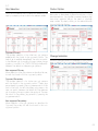
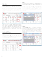
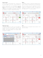
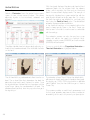
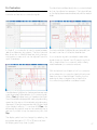
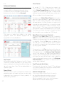
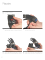
technical information
technical information
2
Contents
1.0 Introduction............................................................................................................. 04-07
1.1 In the Box
1.2 Principal Dimensions
1.3 Specifications
2.0 bebionic Grips......................................................................................................... 09-19
2.1 Factory Settings
2.2 Programme Switch
2.3 Thumb Adjustment
2.4 Opposed Grips
2.5 Non-opposed Grips
2.6 Further Grips and Hand Positions
3.0 bebionic Glove.......................................................................................................... 21-25
3.1 How to fit a bebionic Glove
3.2 Removing a bebionic Glove
3.3 Care Instructions for bebionic Glove
4.0 Connections & Compatibility...................................................................................... 27-35
4.1 Wrist Options
4.2 Battery Options
4.3 Power Information
4.4 System Connections
4.5 System Compatibility
5.0 bebalance ...............................................................................................................37-49
5.1 Introduction
5.2 Installation
5.3 Start up
5.4 Language Selection
5.5 Radio Frequency Module Configuration
5.6 Operating Modes
5.7 Hand Configuration
5.8 Grip Selection
5.9 Advanced
6.0 Additional Information, Warranty, Repairs and Returns...................................................51-63
6.1 Gaiter Removal
6.2 Gaiter Refitting
6.3 Clevis Link Replacement
6.4 Quality Assurance
6.5 Warranty
6.6 Returns
3
1.0 Introduction
This document contains important information
for the correct use and set up of the bebionic3
hand. Please note some of the images may
differ as this document applies to both the
medium and large size of hands. Read this
document throughly before fitting a bebionic3
hand.
A bebionic system is completed by adding from
a selection of compatible system components
including myo electrodes (or other input
devices), battery systems, wrists and cables.
We recommend RSLSteeper components for
all of these requirements.
The bebionic3 hand is designed for mild to
moderate activities. Its use in situations where
heavy loads, vibrations or impacts may be
encountered must be avoided.
Key:
WARNING
Texts with this symbol need special
attention. They contain information to do
with safety.
! Caution
Texts with this symbol draw your attention
to potential sources of damage to the hand.
04
1.1 What’s in the box
5.
1.
2.
7.
3.
6.
4.
1. bebionic radio frequency (RF) module
2. bebionic3 hand
3. bebionic tool kit
4. bebionic in car charger
5. bebalance3 programming software
6. bebionic3 user guide
7. bebionic3 technical information
05
1.2 Principal Dimensions
C
A
B
X
X
D
Principal Dimensions
Large
Medium
A Middle Finger Tip to Hand Base
200mm
190mm
B Thumb Tip to Hand Base
125mm
121mm
C Max Chassis Width (no glove)
92mm
84mm
D Diameter of Chassis at Wrist
50mm
50mm
Palm Circumference (no glove)
220mm
204mm
105mm (with glove)
105mm (with glove)
68o
68o
5mm
5mm
Maximum Opening Width - Tripod Grip
Thumb Swing Through Angle
X EQD Only
06
1.3 Specifications
Part Number
Build Height †
Weight
Description
BBHLG*QD
125mm + 25mm
598g
bebionic3 Large Hand with EQD Wrist
BBHLG*FW
125mm + 37mm
557g
bebionic3 Large Hand with RSLSteeper Friction Wrist
BBHLG*SW
125mm + 12mm
577g
bebionic3 Large Hand with Short Wrist
BBHLG*EU
125mm + 16mm
574g
bebionic3 Large Hand with M12 Thread Stud
BBHLG*NA
125mm + 16mm
572g
bebionic3 Large Hand with 1/2 x 20 UNF Stud
BBHMD*QD
121mm + 25mm
591g
bebionic3 Medium Hand with EQD Wrist
BBHMD*FW
121mm + 37mm
550g
bebionic3 Medium Hand with RSLSteeper Friction Wrist
BBHMD*SW
121mm + 12mm
570g
bebionic3 Medium Hand with Short Wrist
BBHMD*EU
121mm + 16mm
567g
bebionic3 Medium Hand with M12 Thread Stud
BBHMD*NA
121mm + 16mm
565g
bebionic3 Medium Hand with 1/2 x 20 UNF Stud
†
Build height comprises of thumb tip to base of hand measure, followed by the build height for each wrist option.
The second number refers to the minimum allowance for the mating wrist unit.
*Denotes side of hand, i.e. insert L for a left hand, or R for a right hand.
Large
Medium
Maximum Power Grip Force
140.1N
140.1N
Maximum Tripod Grip Force
36.6N
36.6N
Maximum Key Grip Force
26.5N
26.5N
Maximum Time to Open or Close - Tripod Grip
0.5 Seconds
0.5 Seconds
Maximum Time to Open or Close - Power Grip
1.0 Seconds
1.0 Seconds
Maximum Time to Open or Close - Key Grip
1.0 Seconds
1.0 Seconds
Maximum Static Load - Hook Grip
45Kg
45Kg
Maximum Load Individual Finger - Hook Grip
25Kg
25Kg
Maximum Finger Tip Extension Load
6Kg
6Kg
Maximum Safe Vertical Load Taken Through Knuckles
90kg
90kg
07
2.0 bebionic grips
08
The bebionic3 hand provides a
number of grips, allowing the user
to have a more complete device to
assist them in their day to day life.
The hand has two selectable thumb
positions: opposed & non-opposed.
Opposed is where the thumb is in
opposition to the fingers on the hand,
allowing grips like pinch and power.
Non-Opposed is where the thumb is
parallel with the fingers of the hand
and allows grips like key and finger
point.
Opposed
Non-opposed
09
Introduction
2.1 Factory Settings
2.2 Programme Switch
The hand is supplied preset in Mode 4. This provides
two input operation with proportional control of grip and
speed. Speed & grip force are set to maximum.
To alternate between default and alternative grip pattern,
an OPEN OPEN signal must be applied (i.e. the hand
must be fully opened, the signal relaxed and then a
second open signal supplied). To alternate between the
primary grip pattern table and secondary grip pattern
table, press the Programme Switch for less than 2
seconds. The Auto Grip feature is turned off.
Primary Opposed
Default - Tripod
Alternative - Power
Primary Non-Opposed
Default - Key
Alternative - Finger Point
Secondary Opposed
Default - Active Index
Alternative - Tripod
Secondary Non-Opposed
Default - Column
Alternative - Mouse
A Programme Switch is provided on the back of the
hand. This has four functions;
1. Switch the hand ON and OFF
A single press for approximately three seconds will
switch the hand OFF. A single press for more than two
seconds will switch the hand ON.
2. Alternate between the primary and secondary
grip patterns
When the hand is switched ON, a single press of less
than two seconds will alternate between the primary and
secondary grip patterns. This will be accompanied by
a short bleep and vibration (if activated on bebalance).
3. Enable / disable the in-hand RF module
With the hand switched ON, a single press for more
than four seconds will enable the RF module. Pressing
the switch again for more than two seconds or
disconnecting the power to the hand will disable the RF
module.
4. Enter / exit glove mode as follows
With the hand switched OFF, press the button until the
thumb begins to drive in. Then release the button.
10
! Caution
Thumb adjustment MUST be done by a
qualified technician or practitioner.
Adjustment.
2.3 Thumb
To achieve certain grips it is necessary to adjust the thumb position. There are two different planes to
move the thumb in and they are detailed below.
Underside of Thumb Bracket
1. Thumb ML Adjuster
2. Thumb Contact Point Adjuster
An adjuster is provided to allow repositioning of the
thumb for contact with either the index and middle
fingers, as in Tripod Grip, or with index finger only, as in
Pinch and Precision Grips. The thumb pivot assembly
is fitted with a slotted screw as shown in diagram 1.
This acts to adjust the friction on an internal clamp and
is loosened by turning two complete turns and pushing
the screw inward. With the clamp slackened the thumb
position can be manually re-positioned. The assembly
must be retightened before electrically driving the thumb.
An adjuster has also been provided to alter the baseline
position of the thumb in order to optimise the contact
point of the thumb tip against the opposing finger(s)
for Tripod, Pinch and Precision Grips. This is done by
moving the thumb either towards the palm or away
from the palm. This adjuster is located under the thumb
bracket as shown above. Using a hex drive the adjuster
should be turned clockwise to move the thumb towards
the palm and anticlockwise to move the thumb away
from the palm. The effect will not be observed whilst
making the adjustment and can only be observed by
resetting the hand i.e. switching the hand OFF and ON
again.
WARNING
Please ensure screw is securely
tightened before resuming use.
11
Grips
2.4 Opposed - Thumb is opposite to the fingers
12
Tripod
Pinch
When the thumb is opposed, the
hand closes into Tripod Grip with
index and middle fingers meeting
the thumb. Ring and little fingers
continue to close until they meet
resistance or the close signal stops.
This type of grip allows users to pick
up, hold and manipulate a variety of
everyday objects such as car keys,
coins, jar lids and pens.
To achieve this grip it is necessary
for the thumb to be manually
repositioned by the practitioner/
technician so that the thumb only
contacts the index finger (See
section 2.3). The thumb only
contacts index finger and is used for
the fine manipulation of objects.
SERIOUS WARNING
NEVER use a bebionic hand with firearms.
Power
Active Index (Formerly Trigger)
With the thumb opposed, all four
fingers close into the palm until
they meet resistance or the close
signal stops. When fingers are
approaching a fully closed position,
the thumb drives in to cover the
fingers for additional grip security.
This pattern allows round objects
such as a ball or a piece of fruit to
be held securely. This grip can also
provide a handshake. Cylindrical
shaped objects such as bottles,
home & garden utensil handles are
also held easily and securely.
With the thumb opposed Active
Index Grip will grasp the handle of
an object with the middle, ring and
little fingers and secure the grip with
the thumb. The index finger will then
close – this may be positioned over
the lever of the device held such
as a spray bottle. The index finger
is under independent user control
and may be positioned accordingly.
To exit Active Index, an open signal
will fully open the index finger before
the other fingers and thumb release
their grip.
13
Grips
2.5 Non-Opposed - Thumb is inline with the palm.
14
Key
Finger Point
In the non-opposed thumb position,
the four fingers partially close. The
thumb then closes onto the side of
the index finger. The thumb position
may be raised and lowered without
moving the other four fingers allowing
for release, capture or reposition
of the object being gripped. This
pattern is ideal for carrying paper
or letters, using a spoon and for
holding a thin flat object such as a
plate, a credit card or a key.
With the thumb in the non-opposed
setting, the user can move to a
Finger Point position. The middle,
ring, and little fingers close against
the palm and the thumb moves
against the middle finger. With this
grip, typing on a keyboard or input
pad, pressing a bell or a button can
be achieved.
Column
Mouse
This grip moves the thumb into the
palm from a non-opposed position.
The fingers then close over the
thumb to provide a fixed column
that can be used as a way to push
heavier objects or larger buttons
and switches. Column is also the
recommended grip for dressing, as
the thumb is kept out of the way.
With the thumb non-opposed, the
thumb and little finger close to hold
the side of the mouse, with the
middle and ring fingers providing
stability. The index finger closes on
to the mouse button and then backs
off to provide the button press. Each
close signal will give a mouse click
whilst an open signal will release the
mouse.
15
Grips
2.6 Further functions of the bebionic3 hand.
16
Precision Open
Precision Closed
To achieve this grip it is necessary
for the thumb to be manually
repositioned by the practitioner/
technician so that the thumb only
contacts the index finger. With the
thumb opposed, the index finger
meets the static thumb allowing
the user to pick up and manipulate
small objects. When this grip is
selected and a close signal is
applied, the thumb closes to the
midpoint of its range and pauses.
The index is then active and under
user control. The middle, ring and
little fingers remain extended.
To achieve this grip it is necessary
for the thumb to be manually
repositioned by the practitioner/
technician so that the thumb only
contacts the index finger. This grip
can be used in situations similar
to the Precision Open Grip but
where extended fingers would be
obstructive, when working at a desk
for instance.
Initially the middle, ring and little
fingers close into the palm. The
thumb moves to the midpoint of its
range and pauses. The Index is then
active and under user control.
Hook
Finger Adduction
With the thumb in opposed, a
partially closed Power Grip gives the
Hook Grip.This is ideal for carrying a
shopping bag or briefcase.
The fingers of the bebionic hand
move together naturally as the
fingers close. This allows the user
to securely grip thin objects, such
as cutlery or a toothbrush, between
the fingers to achieve function in a
different plane. Finger Adduction
is most functional with the hand in
Power Grip but can also be achieved
with the hand in Key and Pinch.
17
Grips
2.6 Further functions of the bebionic3 hand.
Open Palm
Relaxed Hand
With the thumb in the non-opposed
position the hand may be fully
opened to provide a flat palm suitable
for carrying a tray or a plate.
The thumb is set to the non-opposed
position and partially driven in toward
the palm. All the fingers are driven to
a slightly flexed position.
Applying a further signal will drive the
fingers into a carrying position.
18
be yourself
19
3.0 bebionic glove
20
The bebionic glove is made from ! Caution
a multi-layered, variable hardness,
There is no alternative manufacturer
silicone based material, lined with
of cosmetic gloves for the bebionic
fabric mesh. This construction resists
hand and wrist. The use of other
soiling, wear and puncture damage.
gloves may damage the hand and
will void the warranty.
bebionic gloves provide high
compliance with gripped objects.
The fabric liner also allows the glove
to slide over the joints during motion,
this reduces the amount of power
need to drive the hand and increases
battery life.
The standard glove is supplied in 19
skin tones and also in a solid black
colour.
bebionic gloves provide an additional
barrier to dirt, dust and moisture
ingress to the hand. Direct exposure
to water, or situations where dirt and
dust are prevalent should be avoided
as these have the potential to interfere
or damage the hands performance.
21
bebionic glove
3.1 fitting the bebionic glove
1. Move the thumb into the opposed position.
the hand OFF by pressing down the
2. Switch
programme switch on the back of the hand for
approximately three seconds.
! Caution
Do not use talcum powder or lubricant when
fitting the glove.
5. Fold up the base of the glove.
22
6. Pull the glove over the hand
! Caution
Do not attempt to fit the glove unless the
hand is in glove donning mode.
and hold the programme switch for four
The thumb will be in the position shown above
3. Press
4.
seconds. The hand will automatically drive into
when the hand is in glove mode.
glove mode
the fingers and thumb of of the hand
down the programme switch for four
7. Ensure
8. Hold
align correctly with the fingers and thumb of the
seconds to exit glove donning mode and begin
glove.
using the hand.
23
bebionic glove
3.2 Removing the bebionic glove
oppose the thumb. Then turn the hand
Roll up the base of the glove and pull the whole
1. Firstly
2.
OFF by holding down the programme switch for
glove off from the back of the hand.
approximately three seconds. Next put the hand
into glove donning mode by holding down the
programme switch for 4 seconds.
not pull the fingers individually as this can
3. Dodamage
the glove and hand.
24
glove donning mode by pressing and holding
4. Exit
the programme switch for 4 seconds; the hand
will automatically drive out of glove donning mode
and will be active in the default grip.
bebionic glove
3.3 Care instructions and information
Care
Take care when fitting and using silicone cosmetic
gloves. Try to avoid contact with sharp or pointed
objects. The material used will resist most staining
media.
High Definition Nails
Silicone gloves have nails painted by hand following the
manufacturing process. Bonding to the base material
is good.
We do not recommend the use of polystyrene nails
attached with Cyano-acrylic glue as attempts to remove
the nails bonded with this adhesive will permanently
damage the glove.
Cleaning
General soiling can be removed with soap and water.
After cleaning remove all traces of the cleaner and wipe
the surface dry. Most dyes will be fully removed by this
process. A liquid domestic fabric softener can be used
in solution to reduce the ‘tackiness’ of the surface.
For any other enquiries please use the contact details
supplied on the back cover of this document.
25
4.0 connections & compatibility
26
A bebionic system is very versatile
and allows a number of different wrist,
power and connectivity options.
Most options are detailed in the
following section of this document.
However if you have a question
regarding a specific build not outlined
in this document please contact
RSLSteeper.
The bebionic hand may also be used
with other manufacturers electrodes
and wrists. This means the bebionic3
hand can be fitted into an existing
system without having to change
every single component of the
system.
27
4.1 Wrist Options
There are currently 4 wrist options for the bebionic hand.
28
Electric Quick Disconnect
(EQD) -
Short Wrist -
Allows the hand to be removed with a
rotating action. The EQD wrist allows
the patient to quickly rotate and remove/
attach terminal devices as required.
Low profile connector for applications
where there is a long residual limb. A
short wrist lamination assembly is supplied
attached to these hands. The hand can
be rotated against a constant friction,
which can be adjusted by the patient.
Threaded Stem -
Friction Wrist -
A hand plate with a threaded stud is prefitted. Two thread options can be supplied
USA or European standards are available.
Interfaces with a RSLSteeper 50mm,
friction wrist (part C12810). These hands
are supplied pre-fitted with a Friction Wrist
hand plate. The wrist has user adjustable
friction that can be adjusted at any time
through a simple twist action. This option
produces rotations through a range of
320 degrees.
29
4.2 Battery Options
WARNING
Only the following battery options
should be used with the bebionic3.
Use of other battery systems is not
recommended.
30
BBI=2200
BBI=1300S
BBI=2200S
Typical Capacity:
2200mAh
Typical Capacity:
1300mAh
Typical Capacity:
2200mAh
Voltage (Nominal): 7.4V
Voltage (Nominal): 7.4V
Voltage (Nominal): 7.4V
Size: 18.5mm x 36.5mm
x 70mm
Size: 8.6mm x 3mm x
66.5mm (x2)
Size: 18.5mm x 18.5mm
x 70mm (x2)
4.3 Power Information
WARNING
System cables MUST NOT be cut
while power is ON. This will short the
battery and will damage the system.
Any damage caused is considered to
be outside of the bebionic warranty.
Power Cables
A bebionic hand uses five actuators and therefore requires
a higher current supply than single motor devices. This
can be accommodated safely using bebionic power
cables. Other power cable types may not be efficient or
safe. However, cables from other manufacturers may be
adequate for signaling application.
Low Power Condition
When the battery capacity approaches its lower limit, the
hand will begin to slow. With continuous use it will eventually
stop. If the hand stops in a closed position the user can
apply a series of open signals to fully open the hand. The
hand will remain in an open position until the battery is
recharged.
WARNING
The prosthesis MUST NOT be worn
whilst the batteries are charging.
Battery Switch / Charging Module
A ON/OFF switch is integrated into the charge module.
The switch disconnects power completely, and has
2 positions. When the switch is positioned closest to
the charge point, power is OFF and the battery can
be charged by connecting the lead from the bebionic
charger. When the switch is furthest away from the
charge point, power is switched ON. Connecting the
charger to the charge plug will have no effect on the
battery.
The ON/OFF switch / charge module is fitted to the
battery and requires an additional connector cable to
link to the hand.
The connector cable for EQD hands, as shown on
page 32, is supplied with each battery. For short wrist,
friction wrist, or threaded stud wrist options a different
connector cable (CBBHA72), as shown on page 20,
will need to be ordered separately and connected to the
battery pack after removing B27804.
A small laminating dummy is included in the kit. Prior
to lamination this is placed in a suitable location and
orientation on the forearm model. The position is chosen
to allow sufficient space between the inner and outer
sockets and to allow easy access to the switch and
plug point by the user.
WARNING
It is NOT recommended to route the
power supply to the hand without
passing through the switch.
31
4.4 System Connections
The system detailed below is suitable for a
bebionic hand with an
Electronic Quick Disconnect Wrist
BBI=2200
bebionic 7.4v
2200mAH battery
BBI=1300S
bebionic 7.4v
1300mAH split
cell battery
BBI=2200S
bebionic 7.4v
2200mAH split
cell battery
B27804
Battery Switch
& Charge Point
with Cable.
E.50/E.60
2 X Electrode
50Hz or 60Hz
QDACO
Co-axial plug
Please note: Part B27804 is supplied with each battery pack and do not need to be ordered separately.
Components not to scale.
32
The system detailed below is suitable for a
bebionic hand with either a
Short Wrist, a Friction Wrist or a
Threaded Stem
BBI=2200
bebionic 7.4v
2200mAH battery
BBI=1300S
bebionic 7.4v
1300mAH split
cell battery
BBI=2200S
bebionic 7.4v
2200mAH split
cell battery
B27804
Battery Switch
& Charge Point
with Cable.
E.50/E.60
CBBHA72
2 X Electrode
50Hz or 60Hz
Connector Cable
Please note: Part B27804 is supplied with each battery pack and do not need to be ordered separately, however part
CBBHA72 will need to be ordered separately for hands with short wrist, friction wrist, or threaded stem wrist options.
Components not to scale.
33
4.5 System Compatibility
The bebionic hand is potentially compatible with a number of different parts
from other suppliers. A common list is shown on the page opposite.
Please adhere to the advice given below.
! Caution
The bebionic system has not been exhaustively tested with all alternative electrodes, wrists and
control systems. Any damage caused will be held to be outside of the design parameters of our
system.
The statements above do not imply that RSLSteeper recommend or warrant these combinations.
We believe that, on the basis of statements in the literature from these manufacturers
that these combinations will work effectively but it is for the bebionic practitioner to
test and warrant the combination. These combinations may invalidate warranties
given by other manufacturers. The practitioner should confirm the warranty
position with these manufacturers.
Electrodes
We recommend RSLSteeper E.50 or E.60.
Both are available to purchase and are optimised
for use with bebionic3
34
Inputs
Supplier
Part Number
Type of Input
RSLSteeper
E.50 & E.60
MyoElectrode
Otto Bock™
9X18, 9X37
Switch
Otto Bock™
13E125, 13E200, 13E202
MYOBOCK electrode
Otto Bock™
9X50, 9X52
Linear Transducer
LTI
DC200B=
MyoElectrode
LTI
TP01, TP02
Force Sensitive Resistor
Elbows
Supplier
Part Number
Name
Otto Bock™
12K44=
ErgoArm Hybrid plus™
Otto Bock™
12K50=
ErgoArm Electronic plus™
LTI
BE330
Boston Elbow Digital
Motion Control
Utah Arm™ 3 & 3+
Wrist
Supplier
Otto Bock™
Part Number
10S17 + 13E205
Motion Conrol
Wrist Mode
Name
Wrist Rotator and MyoRotronic
MC Wrist Rotator
Type
Compatibility
Program 1
2 Electrodes - Fast Rise
bebionic Mode 4
Program 2
2 Electrodes - Co-Contraction
bebionic Mode 4
Program 3
2 Electrodes - Safety CoContraction
bebionic Mode 4
Program 4
2 Electrodes + 1 Switch - Actuate
& Hold
bebionic Mode 4 & Mode 5
Program 5
1 Electrode - or 1 Linear
Transducer - Quick Pull
bebionic Mode 0 & Mode 3
Please note: Devices or components not listed above are not recommended.
35
5.0 operating instructions
36
bebalance3 has been designed to
give you optimum control over the
new bebionic3 hand. It features many
new tools which will help you and your
patients optimise and customise the
function of the hand.
Language selection, electrode
configuration with a simulation preview
and simplified menu systems are all
included in bebalance3.
Note: Installation disc is affixed to the
inside back cover.
! Caution
Please DO NOT programme or
control a bebionic system with
unapproved, alternative software
or hardware systems. Doing so will
void the warranty.
37
5.1 Introduction
Out of the box, the bebionic hand is pre-configured
with two site proportional myoelectric control (Mode 4)
where an OPEN OPEN signal is used to change grip
patterns. This mode has been chosen to provide a
standard solution that works well for the majority of users
who demonstrate two, well controlled muscle signals.
However, bebalance3 is particularly useful if muscles
produce limited or difficult to control signals, as is often
the case with the higher-level amputation.
With bebalance3 the practitioner may adjust the
operation of the electrode, reset co-contraction signals,
change signal timing features, choose between one or
two electrode or transducer control and enable the Auto
Grip feature. All are able to enhance the users natural
control capability.
bebalance3 software also provides the ability to record
patient information and to record a history of configuration
settings for each hand.
The programming of the hand requires a USB radio
dongle (supplied) to be plugged into the hosting
computer, which when activated, links to the radio
module in the bebionic3 hand.
There is also the capability to read the current
configuration back from the hand and store it against
the user record.
! Caution
This software is not intended for
patient use. Alterations should be
made by the practitioner ONLY.
! Caution
38
Only bebionic v2 and bebionic3
hands can be programmed using
bebalance3
5.2 Installation
1.
Close all open applications
2.
Insert CD into your CD-ROM
3.
Wait for Autorun
4.
Follow instructions on screen
default target directory is C:\users\
1. The
USERNAME\bebalance3 You can choose an
alternative should you wish; however it should
be noted that it is essential that the bebalance
application directory and sub-directories have
read & write permission.
CP210_Win2K_XP_Vista or CP210_Win7
folder. If using a retro operating system it may be
necessary to use software specific to the computer
build.
The latest version of the software can be found
at www.rslsteeper.com/downloads
If setup fails to automatically open, run it manually
from the BBsetup.exe
bebalance V2 can co-reside with bebalance3.
If you are re-installing bebalance3, the existing
version MUST be uninstalled. Although the
existing database will be retained, it is advised
that the previous version is backed up before
proceeding with this installation.
The bebalance3 application requires .Net
Framework 4.0 to operate. If not installed it can
be installed from the CD by opening dotNet
Framework folder and double clicking on
‘dotNetFx40_Full_x86_x64.exe’ Similarly the
radio dongle requires software to be installed
to operate. Specific versions can be found in
39
5.3
Start up
5.5
Radio Frequency (RF) Module Configuration
On opening the application the main screen shown
above will appear. Any greyed out options are currently
not operational. The area highlighted in red identifes the
bebalance version number.
bebalance now has an auto-detect feature for the radio.
You are advised to insert the RF dongle into a USB port
of the computer before starting the application as it will
be detected on start-up.
5.4
Language Selection
However, if you forget, just insert the dongle and either
return to the entry screen menu as highlighted above.
Or, on the configuration screen, click on the button
marked ‘Radio’.
When the radio dongle has been found the message
box will show ‘RF Dongle Found’ highlighted in green.
If not found the message box will show ‘No RF Dongle’
Enabling RF Module on the bebionic Hand
With the hand switched ON, press and hold the
programme switch on the back of the hand for
approximately three seconds until the RF dongle begins
to flash continually.
At the bottom of the entry screen there are hyperlinks
available to select the appropriate language. Those
available are: English, French, German, Spanish and
Portuguese.
40
Note: This function differs from the glove donning mode
as to enable the RF Module the hand must be switched
ON, whereas in glove donning mode the hand is first
switched OFF. The RF Module can be disabled by
pressing for more than 2 seconds. Alternatively you can
disconnect the power to the hand by using the battery
switch.
5.6
Operating Modes
There are six modes. These are selected from the
highlighted box, along with the appropriate control strategy.
Note: Grip change will generate a bleep and / or vibration
if this feature is enabled.
Mode 3
Control Strategy – Single Site Proportional / Threshold
Alternating
-To OPEN hand – the first signal will OPEN the hand; a
configurable delay of 50ms to 2.0s will allow repeat OPENS
if required.
-To CLOSE hand – a signal applied outside of the delay will
CLOSE the hand; a configurable delay of 50ms to 2.0s will
allow repeat CLOSES if required
-To switch between default grip and alternative grip – apply
a further OPEN signal within variable time (up to 2 seconds)
of the hand fully opening
Grip Patterns
Thumb Opposed - up to 4 grip patterns
Thumb Non-opposed - up to 4 grip patterns
Mode 0
Control Strategy – Single Site Threshold
-To OPEN hand – apply signal
-To CLOSE hand – remove signal
Grip Patterns
Thumb Opposed – up to 4 grip patterns
Thumb Non-opposed - up to 2 grip patterns
Mode 1
Control Strategy – Single Site Proportional / Threshold
-To OPEN hand – apply a short burst signal
-To CLOSE hand – apply a sustained signal
-To switch between default grip and alternative grip – apply
a further OPEN signal within variable time (up to 2 seconds)
of the hand fully opening.
Grip Patterns
Thumb Opposed – up to 4 grip patterns
Thumb Non-opposed - up to 4 grip patterns
Mode 2
Control Strategy – Single Site Proportional / Threshold
-To OPEN hand – apply a quick rising stimulus
-To CLOSE hand – apply a slow rising stimulus
-To switch between default grip and alternative grip – apply
a further OPEN signal within variable time (up to 2 seconds)
of the hand fully opening.
Grip Patterns
Thumb Opposed - up to 4 grip patterns
Thumb Non-opposed - up to 4 grip patterns
Mode 4
Control Strategy – Dual Site Proportional / Threshold
OPEN OPEN
-To OPEN hand – apply signal from OPEN electrode
-To CLOSE hand – apply signal from CLOSE electrode
-To switch between default grip and alternative grip – apply
a further OPEN signal within variable time (up to 2 seconds)
of the hand fully opening
Grip Patterns
Thumb Opposed – up to 4 grip patterns
Thumb Non-opposed – up to 4 grip patterns
Mode 5
Control Strategy – Dual Site Proportional / Threshold Cocontract
-To OPEN hand – apply signal from OPEN electrode
-To CLOSE hand – apply signal from CLOSE electrode
-To switch between default grip and alternative grip – apply
a co-contraction signal
Grip Patterns
Thumb Opposed – up to 4 grip patterns
Thumb Non-opposed – up to 4 grip patterns
Please note: Where more than one grip pattern is available, the
practitioner can select the default and alternative grips for both the
primary and secondary grip patterns using bebalance programming
software. Pressing the programme switch on the back of the hand
allows the user to alternate between the primary and secondary set
of grip patterns.
The hand will be delivered pre-set to Mode 4 with
default values set to provide an operational hand
straight out of the box. Configuration via bebalance may therefore not
be essential pre-fitting.
41
5.7
Hand Configuration Introduction
Hand Configuration
Select bebionic on the main menu to open the
configuration screen as shown below. The ‘No RF
Found’ message may be replaced with ‘RF Dongle
Found’.
For most patients, the factory settings on the bebonic
hand will be adequate. However, for experienced
practitioners bebalance software can be used to
customise each hand to each individual through the
bebionic menu option.
Configuration essentially changes the way the bebionic
hand operates. These changes are downloaded from
the computer to the hand to allow the user to try them.
Successful alterations can be loaded and saved in
the hands memory. Details of individual iteration, once
saved, are with the patient’s ID in the History file.
! Caution
Only bebionic v2 and bebionic3 hands can be
programmed using bebalance3
42
By default the configuration screen opens with dual
-site control strategy. You can change to single-site
by point & click on the single-site ‘radio button’
under Control Strategy.
5.8
Grip Selection
Grips can be selected and ordered as desired by the
user by a simple point and click in the relevant tables.
Opposed Primary
This enables selection of the initial two grip patterns
available with the thumb in the opposed position. The
default grip is available immediately, the user can switch
to the alternate grip by applying the appropriate change
signal e.g. in mode 4, an OPEN OPEN signal will switch
between the default and alternate grip patterns.
Control Option
The hand can be controlled by proportional or threshold
electrodes or alternatively by linear transducers or force
sensitive resistors. It is possible to reverse the electrode/
transducer operation without the need to physically
swap cables. By simply clicking on the electrode radio
buttons highlighted below.
Change Indication
Function change indication is available by ticking either
beep or vibrate, both or none as highlighted below.
Non-opposed Primary
Allows selection of the grip patterns as described above,
but with the thumb in the non-opposed position.
Opposed Secondary
This enables selection of a further two grip patterns
with the thumb in the opposed position. These grips
are activated by pressing the programme switch on the
back of the hand. As with the primary grip patterns, the
user can switch between the default and the alternate
grip by applying the appropriate change signal. The user
can return to the primary grip patterns by pressing the
programme switch.
Non-opposed Secondary
Allows selection of the grip patterns as described for
Opposed Secondary but with the thumb in the nonopposed position.
43
Auto Grip
This feature can be set to enabled or disabled. Note
that Auto Grip functions in Tripod Grip only. Auto Grip is
activated by providing three consecutive close signals.
De-activation occurs when the hand is opened. Reactivation is made again by three consecutive close
signals.
When Auto Grip is active, the electronics monitors
motor position for movement. If movement /slippage
of an object is detected, the finger position/grip force
is automatically altered to provide a more secure grip.
Electronic monitoring of this process occurs every
50ms.
Horizontal Buttons
Reset
If at any time you want to start again with your
configuration, clicking Reset, resets all the controls to
the default settings for the current mode.
44
Save
The hand can be configured and the settings sent to
the hand without saving if you want to give them a try. If
you wan to retain these settings for further amendment
or back-up you need to click Save. Before the data
is saved a patient identifier must be entered. There is
a description field for recording specific information as
necessary.
History
Clicking History opens a list of saved configurations.
By entering a patient identifier and clicking on the Find
button you can filter the records to only show the relevent
records. This feature enables the recovery of previous
settings for re-sending to the hand or providing a base
to work from.
Send to Hand
With the radio dongle inserted and configured and
the radio activated on the hand. It starts transmitting a
stream of signals, which can be identified by the rapid
flashing of the LED on the dongle. Clicking Send to
Hand starts the transmission of the current configuration
to the hand. On completion the message panel on the
right will show success or in failure of the process.
Radio
This enables connection of the radio module should you
forget to install the dongle before running the application.
When the dongle is found the message box will ‘RF
Dongle Found’ highlighted in green. If not found the
message box will show ‘No RF Dongle’ highlighted in
red. See section 8.1 for more information.
Read from Hand
This feature enables the current hand configuration to
be read from the hand and stored in the history file.
Following a read you are required to enter a patient
identifier. This enables retrieval of the specific patient
configuration, if desired.
Quit
This will close the configuration form and return to the
main entry screen.
45
Vertical Buttons
Electrodes
Selecting Electrodes from the vertical button menu
opens a form, shown second below. This allows
electrode signals to be monitored, reviewed and
adjusted.
With the signals displayed the electrode threshold and
maximum levels can be adjusted with the relevant
sliders, which reposition the blue and red horizontal
lines in the associated display panels. The strength of
the signal is displayed as a green vertical bar with the
peak signal indicated as single green line. On closing
the form the settings are retained for configuring the
hand using the Send to Hand option. The embedded
animation system enables modification
of the threshold settings to be sampled without the
need to keep sending data to the hand. These can
then be sent to the hand once the user is comfortable
with the settings.
The animation system can also be used as a pure
training aid without the need for a bebionic hand.
However a training tower (XXXXXXX) and radio module
(XXXXXXX) will be required.
46
The sliders identified are for independently adjusting onthreshold and maximum levels of the individual channels
on the hand.
To turn on, point & click on Proportional Animation or
Threshold Animation as highlighted below.
The off threshold is a predetermined offset from the on
level. The on level (blue line) determines the level the
electrode signal must reach before it is active. Once
the signal reaches this level the hand operates until the
signal drops below the predetermined off level. The
maximum level (red line) sets the proportional range of
the signal input.
The animation shows Tripod Grip as the default which,
will open and close in response to the electrode signals.
By applying an OPEN OPEN signal within a definable
period (default 1sec) the hand will change to / from a
Power Grip.
This system provides a useful ‘myo’ assessment tool
for the upper extremity amputee and also provides an
entertaining aid for use, both pre and post prescription.
Co-Contraction
Selecting Co-Contraction opens a form, shown below,
to monitor and set the co-contraction signals.
‘In Mode 5, co-contraction is used to move between
default and alternate grip patterns. The blue horizontal
lines show the on threshold level set during the myo
configuration process and can be adjusted from this
option if necessary.
The black horizontal lines identify the co-contraction level
and can be adjusted as necessary. The horizontal lines
on the display area move simultaneously with the vertical
slider.
The horizontal slider highlighted above (centre left) can
be used to set the co-contraction time window.
A co-contraction signal is considered to exist when
signals from both channel 1 and 2 pass through both
the on threshold and co-contraction within a designated timeframe (co-contraction window).
With the bebionic hand there is a 'soft' co-contraction
option where the co-contraction threshold can be set
lower than the on threshold level. Providing that the
peak signal does not exceed the on-threshold, a
co-contraction signal will be considered to exist.
The slider items highlighted on the image above are used
to set the required characteristics of co-contract signals.
Clicking Start will initiate tracing of the electrode signal.
One channel will be displayed with raising signals moving
upward and the second channel raising signals moving
downward. When the trace reaches the right hand side
of the display it will stop. To continue click Clear, this
will remove the previous trace and automatically start a
new one. If you wish to stop the trace at any point, click
Stop.
The display period can be changed by selecting the
appropriate time period (10, 20 or 30 seconds) from
the display period drop down (top left).
47
5.9
Advanced Features
In bebalance3 the basic features can be selected
by simply clicking on the appropriate radio button
or check box control. Adjustment of more specific
features can be done by clicking Advanced.
Timer Control
For modes 1, 2, 3 & 4 there are two numeric up/
down controls to change mode timings. The upper
control Mode Change Period sets the window of time
to search for a mode change signal. In these modes
additional signals received will have have no effect and
will be considered to be the same signal.
The lower control Mode Return Period sets the period
after which the mode reverts to default where there has
been no activity. Setting the slider to zero deactivates
the revert feature. For Mode 5 there is no upper control
as mode change is activated by a co-contraction signal.
Dwell Threshold (Upper & Lower) This feature is only
used on Mode 1. The Upper control sets the time that
the signal has to exist to be identified as a CLOSE signal.
The Lower control sets the value for the period a signal
has to be held once considered an OPEN signal.
This opens an overlay form similar to the screen
highlighted below. The features displayed will be
appropriate to the mode selected.
Grip Current
It is possible to selet High, Medium or Low Grip Current.
This setting provides adjustment of grip strength and
battery consumption; the lower the setting the lower the
grip and current draw. Note: This has minimal effect on
operation speed.
Speed Control
Should you want to open or close the hand at less than
maximum speed, the numeric up/down controls provide
independent hand opening and closing speeds; 40
(default) being maximum.
48
Signal Select & Increase on Threshold
This feature offers Open & First protocols. The default is
Open which means that the hand will move in response
to receipt of the larger signal if both exceed the electrode
on threshold. When the First option is selected, the
hand will open on receipt of the first signal to exceed
the threshold and remains with this signal even if a larger
opposing signal is received.
The exception to the First signal protocol is when an
opposite signal exceeds the value of the controlling signal
by the amount set on the Minimum Dwell Threshold
control. If this happens the larger signal becomes the
dominant signal. If multiple signals are received to open
and close, the hand will continue to open unless the
close signal exceeds the amount set on the Minimum
Dwell Threshold control, which is a value above the
standard electrode level.
Dwell Threshold (Min & Max)
This feature is only used on Mode 2. The minimum
control sets the level that the signal has to exceed within
a time set by the maximum control.
Direction Change Timer
This control is used in Mode 3 only. It is used to
set the additional time window when a second
signal will be accepted as an additional same
direction movement. If set to zero, hand movement
will alternate with the next detected signal.
be confident
49
6.0 additional information,
warranty, returns and
repairs
50
There are a number of field repairs and
replacement parts that are available for
the bebionic3. The instructions for how
to do this are described in this section.
For further advice on any repairs please
contact your bebionic distributor or
email: [email protected].
For both parts and service, please
mention that the hand is a bebionic3
hand; including details as the whether
it is Large or Medium, Left or Right
and the date of purchase.
51
Repairs
6.1 Gaiter Removal
the rear strap down and over the EQD to
Tilt the hand backward and stretch the strap
1. Pull
reveal the serial number on the back of the hand. 2. over the bottom of the EQD.
the gaiter away from the palm of the hand,
Taking care to avoid the thumb cable, pull the
5. Pull
6.
making sure that the thumb cable stays in position.
gaiter over the thumb and off the bebionic3 hand.
52
the screwdriver with the 1.50mm hex bit
4. Slide gaiter flaps out from under the rear cover.
3. Using
contained within the toolkit, loosen the screws in
the rear cover.
Note: Do not completely remove.
7. Completely remove the gaiter from the hand.
the thumb cable position, as this is key
8. Note
when refitting a new gaiter.
53
Repairs
6.2 Gaiter Refitting
the thumb section of the gaiter over the
Ensure the thumb section of the gaiter is pushed
1. Slide
thumb. Ensure the gaiter strap is under the thumb. 2. all the way to the gap shown in the image above.
Pay special attention to the thumb cable position.
push the flap all the way home under the
Ensure there is as small a gap as possible
6.
5. Carefully
rear cover.
between the gaiter and the rear cover.
54
the gaiter strap around to the rear of the hand
up the sections of the hand highlighted
3. Pull
4. Line
and up over the EQD.
with the sections of the gaiter highlighted when
pushing the gaiter flaps under the rear cover. Pay
special attention to the thumb cable position.
both of the screws in the rear cover.
Finished!
7. Retighten
8.
Note: Do NOT overtighten.
55
Repairs
6.3 Clevis Link Replacement
clevis link has been designed to bend, should
Firstly ensure the thumb is in the non-opposed
1. The
the hand be excessively loaded during use. If this 2. position and that all of the fingers are fully driven
should occur the part will need to be replace so
that the finger can be driven again.
5.1
Circle indicates correct side
for inserting pivot pin.
open. Then remove the pivot pin with the
bebionic pivot removal pliers (Part:508-27430*).
Alternatively the pivot can be removed with the pin
punch provided in the tool kit.
*available for purchase seperately.
the finger flexed, use needle point pliers
Using a pair of standard pliers ensure that the
6.
5. Keeping
pivot pin sits flush with the surface on both sides
to insert the pivot pin through both parts of the
56
link.
Note: The pin is tapered and can only be inserted
from the side with the circle detailed in image 5.1.
of the link.
a spare clevice link from the tool kit. Place it
Bend finger forward to align the holes for the pivot
3. Using
into the slot in the proximal. Ensure that the curve 4. pin.
of the clevice link curves away from the finger
towards the palm.
Note: Clevis curving towards the palm.
that the finger flexes fully forward and
Finished!
7. Ensure
8.
springs back to the upright position as shown in
the two images above.
57
6.4 Quality Assurance
RSLSteeper operate a UKAS approved quality management system and fully complies with the
requirements of BS EN ISO 9001:2008, ISO27001:2005 & TickIT Issue 5. This certifies that RSLSteeper
meet the appropriate international quality standards for design, manufacture and supply of prosthetic
products and user software.
RSLSteeper is registered with both the Medicines and Healthcare Regulatory Authority in the UK and
the Food and Drugs Administration of the United States Government for the manufacture and supply of
prosthetics and orthotics products.
MHRA Registration N°: CA001031
FCC Registration N° : PBBGC350616
FDA Registration N° : 9612243
IC : 10634A-RSLRFBB
Model N°: RSL-RP609
Continued compliance with the standard is monitored by a programme of internal and external based
audits.
All individual products are marked indicating that they comply with the requirements of the Medical
Devices Directive 93/42/EEC (MDD).
The
mark may be applied on packaging, accompanying literature or an enclosure, rather than the
product itself.
The bebionic hand and its associated components listed in this document are covered by test
certificates for:BS EN 60601-1-2-2007
Electromagnetic Compatibility for Electronic Hand (EMC)
BS EN 60601-1-2006
Medical Electrical Essential requirements for Safety
BS EN 60950-1-2006
Information Technology Equipment for Safety
ETSI 300 440-2 V1.3.1 (2009-03)
Electromagnetic Compatibility for RF Module
ETSI 301 489-3 V1.4.1 (2002-08)
Electromagnetic Compatibility for RF Module
Additional internal and external test results and associated project documentation can be found in the
Technical File RP609.
58
8747
FCC Warning Statement
• This device complies with Part 15 of the FCC Rules.
Operation is subject to the following two conditions:
1.This device may not cause harmful interference and
2.This device must accept any interference received, including
interference that may cause undesired operation.
• This equipment complies with FCC radiation exposure
limits set forth for an uncontrolled environment. End users
must follow the specific operating instructions for satisfying
RF exposure compliance. This transmitter must not be colocated or operating in conjunction with any other antenna or
transmitter.
• Changes or modifications not expressly approved by the
party responsible for compliance could void the user’s
authority to operate the equipment.
• The RSLSteeper bebionic Medium Hand, Model:
RSL-RP609, complies with Part 18 of the FCC Rules
(Section 18.212).
• The antenna(s) used for this transmitter must be installed
to provide a separation distance of at least 20cm from all
persons.
• The End product must have a label stating ‘Contains FCC
ID:PBBGC350616’ place on it inline with FCC labelling
regulations.
The FCC and IC information is located on the outside of the palm
of each hand (left and right) underneath the gaitor.
59
INDUSTRY CANADA STATEMENTS
This device complies with Industry Canada licence-exempt RSS standard(s). Operation is
subject to the following two conditions: (1) this device may not cause interference, and (2)
this device must accept any interference, including interference that may cause undesired
operation of the device.
Under Industry Canada regulations, this radio transmitter may only operate using an
antenna of a type and maximum (or lesser) gain approved for the transmitter by Industry
Canada. To reduce potential radio interference to other users, the antenna type and its
gain should be so chosen that the equivalent isotropically radiated power (e.i.r.p.) is not
more than that necessary for successful communication.
This radio transmitter (IC:ID : 10634A-RSLRFBB) has been approved by Industry Canada
to operate with the antenna types listed below with the maximum permissible gain and
required antenna impedance for each antenna type indicated. Antenna types not included
in this list, having a gain greater than the maximum gain indicated for that type, are strictly
prohibited for use with this device.
Name / Model
7488910245/Wurth
Gain
1,0
Impedance
50 Ohm
OEM Responsibilities
The RSL-RP609 Module has been certified for integration into products only by OEM
integrators under the following conditions:
1.
The antenna(s) must be installed such that a minimum separation distance of 20cm
is maintained between the radiator (antenna) and all persons at all times.
2.
The transmitter module must not be co-located or operating in conjunction with any
other antenna or transmitter.
As long as the two conditions above are met, further transmitter testing will not be
required. However, the OEM integrator is still responsible for testing their end-product for
any additional compliance requirements required with this module installed (for example,
digital device emissions, PC peripheral requirements, etc.).
60
IMPORTANT NOTE:
In the event that these conditions can not be met (for certain configurations or co-location
with another transmitter), then Industry Canada certification is no longer considered
valid and the IC Certification Number can not be used on the final product. In these
circumstances, the OEM integrator will be responsible for re-evaluating the end product
(including the transmitter) and obtaining a separate Industry Canada authorization.
End Product Labeling
The RSL-RP609 Module is labeled with its own IC Certification Number. If the IC Certification
Number is not visible when the module is installed inside another device, then the outside
of the device into which the module is installed must also display a label referring to the
enclosed module. In that case, the final end product must be labeled in a visible area with
the following:
“Contains Transmitter Module IC RSL-RP609
or
“Contains IC: RSL-RP609”
The OEM of the RSL-RP609 Module must only use the approved antenna(s) listed above,
which have been certified with this module.
The OEM integrator has to be aware not to provide information to the end user regarding
how to install or remove this RF module or change RF related parameters in the user’s
manual of the end product.
The user’s manual for the end product must include the following information in a prominent
location:
“To comply with Industry Canada RF radiation exposure limits for general population,
the antenna(s) used for this transmitter must be installed such that a minimum
separation distance of 20cm is maintained between the radiator (antenna) and all
persons at all times and must not be co-located or operating in conjunction with
any other antenna or transmitter.”
61
Radio Equipment - Canadian Warning
Statements
Radio Equipment - Canadian Warning Statements
English
"Under Industry Canada regulations, this radio transmitter may only operate
using an antenna of a type and maximum (or lesser) gain approved for the
transmitter by Industry Canada.
To reduce potential radio interference to other users, the antenna type and its
gain should be so chosen that the equivalent isotropically radiated power (e.i.r.p.)
is not more than that necessary for successful communication."
"This device complies with Industry Canada licence-exempt RSS standard(s).
Operation is subject to the following two conditions:
(1) this device may not cause interference, and
(2) this device must accept any interference, including interference that may
cause undesired operation of the device."
French
"Conformément à la réglementation d'Industrie Canada, le présent émetteur
radio peutfonctionner avec une antenne d'un type et d'un gain maximal (ou
inférieur) approuvé pour l'émetteur par Industrie Canada.
Dans le but de réduire les risques de brouillage radioélectrique à l'intention des
autres utilisateurs, il faut choisir le type d'antenne et son gain de sorte que
la puissance isotrope rayonnée équivalente (p.i.r.e.) ne dépasse pas l'intensité
nécessaire à l'établissement d'une communication satisfaisante."
"Le présent appareil est conforme aux CNR d'Industrie Canada applicables
aux appareils radio exempts de licence. L'exploitation est autorisée aux deux
conditions suivantes :
(1) l'appareil ne doit pas produire de brouillage, et
(2) l'utilisateur de l'appareil doit accepter tout brouillage radioélectrique subi,
même si le brouillage est susceptible d'en compromettre le fonctionnement."
“To comply with industry Canada RF radiation exposure limits for general
population, the antenna(s) used for this transmitter must be installed such that
a minimum separation distance of 20cm is maintained between the radiator
(antenna) and all persons at all times and must not be co-located or operating
in conjunction with any other antenna or transmitter.”
62
6.5 Warranty
Warranty Terms
Item
Warranty Period
Warranty Terms
bebionic Hand
12 months
Design and Manufacture
Cables
12 months
Design and Manufacture
Wrist
12 months
Design and Manufacture
Batteries / Chargers
12 months
Design and Manufacture, correct charging
Gloves
3 months
Design and Manufacture, not wear and tear
An extended warranty is available for the bebionic hand, providing additional cover for year 2 or years 2+3.
Hand Policy
Hands returned to the RSLSteeper bebionic service centres will be assessed and where deemed beyond
repair will be replaced where a claim is made under warranty, this claim must be supported by appropriate
documentation. The warranty will be void on all system components if any components have been subject
to abuse, repair or maintenance by an uncertified person, deliberate damage, loads beyond those for
which the product was designed or by modification or neglect. You must state that you wish us to supply
a replacement.
Glove Policy
Cosmetic gloves are only replaceable under warranty where the failure is due to a manufacturing fault as
we have no control over the environment in which they are used. Please inspect the glove at first fitting to
identify any faults so that we can provide a replacement where this is necessary.
To identify the hand serial number, lift the gaiter on the back of the hand. The serial number can be found
underneath.
Please note: Each bebionic hand is fitted with a passive Radio Frequency Identity Device to allow
identification and trace during manufacture and in case of return to our bebionic service centres.
6.6 Returns
If bebionic components are to be returned for servicing please contact us at: [email protected]
stating the hand serial number. We will issue a returns number and returns form that will need completeing
in full so that your request can be dealt with promptly.
Spare Parts Policy
Some components of a bebionic system are replaceable by bebionic accredited practitioners.
For further advice on any repairs please contact your bebionic distributor or email: [email protected].
For both parts and service, please mention that the hand is a bebionic3 hand; including details as the whether it is Large
or Medium, Left or Right and the date of purchase.
63
Notes
64
Notes
65
Notes
66
Installation Disc
Please refer to page 36 for installtion instructions
67
www.bebionic.com
be confident
Technical Support
Manufacturing Centre, Unit 7,
Hunslet Trading Estate,
Severn Road,
Leeds, LS10 1BL, UK
Tel: +44 (0) 113 270 4841
e: [email protected]
Technical Support
3619 Paesanos Parkway,
Shavano Center III, Suite 200,
San Antonio, 78231
Texas. USA
Tel: 210 481 4126
e: [email protected]
RSLLIT317 Issue 2 2012