1
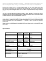
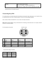
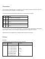
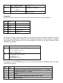
Pt104 Manual v1.0
1. Introduction
2. Connecting to PC
3. Specifications
4. Principles of Operation
5. Technical Information
Writing you own software overview
Other Information
Safety Warning
The ground of the pt104 is connected directly to the ground of your computer, in order to minimise
electrical interference.
Take care when using bare-wire platinum resistance thermometers that they do not come into
contact with voltages outside the operating range of the pt104, as you may risk damage to the
pt104 and your computer.
When measuring temperatures on mains equipment, we recommend the use of insulated
thermometer probes. If a sensor input is accidentally connected to mains, your computer chassis
may become live.
Introduction
The pt104 is a four channel, high resolution temperature converter for use with Pt100 and Pt1000
type sensors. It can also be used to measure resistance and voltage.
In Pt100/Pt1000/resistance mode, the unit uses a four-wire circuit and applies a continuous sense
current of 250uA. For Pt100 and 0..500 ohms, the signal passes through an amplifier with a gain
of 21: for Pt1000 and 0..10k, it feeds directly into the ADC. The sense current passes through the
input resistor and through and internal, 3ppm reference. The value of this resistor is stored in
EEPROM inside the unit. Yearly calibration is recommended.
In voltage mode, the input connector can be treated as a differential input with ground, or two
single ended inputs. Both inputs must be zero volts or above, though it does not matter which
input has the higher voltage. The accuracy on the 2.5V range depends on the accuracy of the
internal voltage reference. For the 113mV range, it also depends on the accuracy of the x21
amplifier. This may vary by 2%, and has a tempco of 100ppm/degC.
Principles of operation
Platinum resistance thermometers (PRTs) offer excellent accuracy over a wide temperature range (from -200
to 850 C). Sensors are interchangeable between different manufacturers, and are available in various accuracy
ratings in packages to suit most applications. Unlike thermocouples, it is not necessary to use special cables to
connect to the sensor.
The principle of operation is to measure the resistance of a platinum element. The most common type (PT100)
has a resistance of 100 ohms at 0 C and 138.4 ohms at 100 C. There are also PT1000 sensors that have a
resistance of 25 ohms and 1000 ohms respectively at 0 C.
The relationship between temperature and resistance is approximately linear over a small temperature range:
for example, if you assume that it is linear over the 0 to 100 C range, the error at 50C is 0.4 C. For precision
measurement, it is necessary to linearise the resistance to give an accurate temperature. The most recent
definition of the relationship between resistance and temperature is International Temperature Standard 90
(ITS-90). This linearisation is done automatically, in software, when using Pico signal conditioners.
The linearisation equation is
Rt = R0 * (1 + A* t + B*t2 +C*(t-100)* t3)
A = 3.9083 E-3
B = -5.775 E-7
C = (below 0 C) -4.183 E -12
(Above 0 C) zero
For a Pt100 sensor, a 1 C temperature change will cause a 0.384ohm change in resistance, so even a small
error in measurement of the resistance (for example, the resistance of the wires leading to the sensor) can
cause a large error in the measurement of the temperature. For precision work, sensors have four wires - two to
carry the sense current, and two to measure the voltage across the sensor element. It is also possible to obtain
three-wire sensors, although these operate on the (not necessarily valid) assumption that the resistance of each
of the three wires is the same.
The current through the sensor will cause some heating: for example, a sense current of 1mA through a 100
ohm resistor will generate 100uW of heat. If the sensor element is unable to dissipate this heat, it will report an
artificially high temperature. This effect can be reduced by either using a large sensor element, or by making
sure that it is in good thermal contact with its environment.
Using a 1mA sense current will give a signal of only 100mV. Because the change in resistance for a degree
celsius is very small, even a small error in the measurement of the voltage across the sensor will produce a
large error in the temperature measurement. For example, a 100uV voltage measurement error will give a 0.4 C
error in the temperature reading. Similarly, a 1uA error in the sense current will give 0.4 C temperature error.
Because of the low signal levels, it is important to keep any cables away from electric cables, motors, switch
gear and other devices that may emit electrical noise. Using screened cable, with the screen grounded at one
end, may help to reduce interference. When using long cables, it is necessary to check that the measuring
equipment is capable of handling the resistance of the cables. Most equipment can cope with up to 100 ohms
per core.
The type of probe and cable should be chosen carefully to suit the application. The main issues are the
temperature range and exposure to fluids (corrosive or conductive) or metals. Clearly, normal solder junctions
on cables should not be used at temperatures above about 170 C.
Sensor manufacturers offer a wide range of sensors that comply with BS1904 class B (DIN 43760): these
sensors offer an accuracy of ±0.3 C at 0 C. For increased accuracy, BS1904 class A (±0.15 C) or tenth-DIN
sensors (±0.03 C). Companies like Isotech can provide standards with 0.001 C accuracy. Please note that these
accuracy specifications relate to the SENSOR ONLY: it is necessary to add on any error in the measuring
system as well.
Related standards are IEC751 and JISC1604-1989. IEC751 also definesthe colour coding for PRT sensor
cables: the one or two wires atttached to one end of the sensor are red, and the one or two wires at the other
end are white.
Specification
Temperature
Sensor
Pt100*, Pt100
Range
-200..800C
Resistance
Voltage
0..375 ohms*
0..115mV
0..10k ohms
0..2.5V*
Linearity
10ppm
10ppm
TBA
Accuracy @25C
0.01C
20ppm
0.2%
Temperature coefficient
3ppm/degC
3ppm/degC
100ppm/degC
Noise
0.01C
10ppm
10ppm
0.001C
1uohm
0.156uV
(95% confidence limit)
Resolution
Number of inputs
4
Connectors
4-pin miniDIN
Input impedence
>>1MOhm
Overvoltage protection
+/-100V
Output
Environmental
RS232, D9 female
20-30C for stated accuracy
0-70C overall
20-90% RH
Software
PicoLog data logging software
Drivers for Windows 3.1/95/98/NT/2000/ME/Linux
Examples for C, Delphi, Excel, Labview, Labwindows, HP-VEE
Quoted accuracy is for options marked *
Connecting the pt104
To use the pt104, you should connect the D-connector on the pt104 to the serial port on your computer using
the cable provided. If you have a 25-way serial port, use the 9 to 25 way adaptor supplied.
Next, connect a Pt100 or Pt1000 PRT to one or more of the input connectors.
Note: When using the pt104 in noisy environments Pico Technology recommends the use of quality screened
sensors for accurate readings.
Pin Connections to the pt104
Pin
Mini-Din socket
Pt100, Pt1000
Pt100, Pt1000
Pt100, Pt1000
4 Wire
3 Wire
2 Wire
1
White
Connect to pin 3
Connect to pin 3
Do not connect
2
Red
Red
Red
V-
3
White
White
White
V+
4
Red
Red
Connect to pin 2
Gnd
Single ended voltage connection
Connector
1
2
Channel
Pin
1
3
5
2
2
3
Differential voltage
3
4
6
2
3
3
7
2
4
3
8
2
NOTE: Differential Mode.
The maximum input voltage range of the PT104 is 2.5V. Any voltage in excess of +/-30V on any input pin may
cause permanent damage to the unit.
In Differential Voltage Mode, the input connector should be treated as a differential input with reference to
ground. Both inputs (V+ and V-) must be zero volts or above (it does not matter which input has the higher
voltage) and must remain within the input range. A ground reference connection is also required for correct
operation.
The Ground connection of each MiniDIN socket consists of a 100 Ohm resistor to mains earth/ground via the
serial cable outer braiding and the PC chassis.
To check that the unit is working:
• start up PicoLog
• select the File menu
• select New Settings
• In the recording window, press OK
• In the sampling window, press OK
• In the converters window, Select pt104
• Select the port that the pt104 is connected to
• Press OK
• Select channel 1
• Type in a channel name
• Select the data type required i.e temperature, resistance or voltage
• Select circuit - for PT100 and PT1000
• Press OK
Readings from the pt104 should appear in the monitor window.
Note: on standard IBM compatible computers, only two interrupts are assigned for serial ports. If you wish to
use more than two pt104 units, each pt104 must have its own interrupt, so you will need a serial port
card which can be set to non-standard interrupt settings.
For more information on serial port see serial port settings.
To connect to a modem see modem operation
Overview
The pt104 is supplied with driver routines that you can build into your own programs.
Once you have installed the software, the DRIVERS directory contains the drivers and a selection of examples
of how to use the drivers. It also contains a copy of this manual as a pdf file. If you installed under Windows, the
Pico Technology group contains a help file for the drivers. See the Readme.doc file in the DRIVERS directory
for the filenames.
The driver routine is supplied as object files for DOS and protected mode, and as a Dynamic Link Library for
Windows.
The object files use Pascal linkage conventions and do not require any compiler run-time routines: they can
therefore be used with most real-mode and some protected-mode C and Pascal compilers.
The Windows DLL can be used with C, Delphi and Visual Basic programs: it can also be used with programs
like Microsoft Excel, where the macro language is a form of Visual Basic. More than one application can access
the Windows DLL at the same time, as long as the applications do not change the settings for channels that
they are not using.
Operating Systems
DOS
Windows 3.x
Windows 95/98/ME
Windows NT/2000
Linux
The following table specifies the function of each of the routines in the driver:
Routine
Function
pt104_open_unit
Open the driver to use a specified serial port(s)
pt104_close_unit
Close the port (ALWAYS DO THIS!)
pt104_poll_driver
Poll the driver (not usually necessary)
pt104_get_cycle
Find out when the driver has taken a new set of readings
pt104_set_channel
Specify the sensor type and filtering for a channel
pt104_set_mains
Specify the mains setting 50 or 60 Hz
pt104_get_value
Get the most recent data reading from a channel
pt104_get_version
Get the version number of this pt104
pt104_get_unit_info
Get the version number, calibration number, calibration date and
batch number of this pt104
pt104_get_driver_version
Get the version number of the driver
pt104_labview
Easy to use interface for Labview
The normal calling sequence for these routines is as follows:
Open driver
Set Channels
While you want to read data,
Get data
End While
Close Unit
Close Driver
pt104_open_unit
DOS version:
unsigned short pt104_open_unit (
unsigned short
port,
unsigned short
base,
unsigned short
irq);
Windows version:
unsigned short pt104_open_unit (
unsigned short
port);
This routine specifies the serial port number with an pt104 unit. If you wish to use more than one pt104, you
should call the routine once for each pt104.
The port must be 1 for COM1, 2 for COM2, etc.
Under DOS, this routine has extra parameters to specify the base address an interrupt number for the COM
port. These can be set to zero for the default base address and IRQ. Under Windows, the base address and
IRQ information is defined in your WIN.INI file, so it is not necessary to specify a value.
This routine returns TRUE if the driver successfully opens the pt104
pt104_close_unit
void pt104_close_unit (unsigned short port);
This routine disconnects the driver from the specified serial port.
If you successfully open any serial ports, you MUST call pt104_close_unit for each port before you exit from
your program. If you do not, your computer may misbehave until you next reboot it.
pt104_poll_driver
void pt104_poll_driver (void);
It is not normally necessary to call this routine, as the driver uses the timer to poll the pt104. Some programs,
like Excel, appear block the timer and so it is necessary to poll the driver periodically whilst waiting for data.
pt104_get_cycle
unsigned short pt104_get_cycle
(unsigned long far * cycle,
unsigned short
port);
This routine returns the number of complete cycles of readings taken from a particular pt104
When you call pt104_get_value, it returns immediately with the most recent reading for the specified
channel. If you call it repeatedly, it will return the same reading repeatedly, until the driver takes the next reading
from that channel.
If you wish to record values only when the driver has taken a new reading, you can use this routine to find out
how many complete cycles of readings the driver has taken, then you can call pt104_get_value only when a
cycle has completed.
Note: each pt104 is polled independently, so the cycle numbers for multiple pt104s may not keep in step.
pt104_set_channel
void pt104_set_channel (
unsigned short
port,
unsigned short
channel,
unsigned short
data_type
unsigned short
no_of_wires);
You should call this routine once for each channel that you would like to take readings from. You can do this any
time after calling pt104_open_unit.
The fewer channels are selected, the more frequently these channels will be updated: it takes about 1 second
per active channel.
channel specifies which channel you want to set the details for: it should be between 1 and 4 or between 1 and
8 if using single ended inputs in voltage mode.
data_type set to the type of reading you require (1 for pt100, 2 for pt1000, 3 for resistance 0..375R, 4 for
resistance 0..10k, 5 for differential voltage 0..100mv, 6 for differential voltage 0..2V5, 7 for single ended voltage
0..100mv and 8 for single ended voltage 0..2V5
no_of_wires specifies how many wires the pt100 or pt1000 has (set to 2, 3 or 4)
pt104_set_mains
void pt104_set_mains (
unsigned short
sixty_hertz);
This routine is used to select the mains frequency of 50 or 60Hz.
For fifty hertz set sixty_hertz to zero
For sixty hertz set sixty_hertz to one.
Choosing the incorrect frequency may increase suceptibility to electrical noise.
pt104_get_value
unsigned short pt104_get_value (
long far *
data,
unsigned short
port,
unsigned short
channel,
unsigned short
filtered);
Once you open the driver and define some channels, the driver constantly takes readings from the pt104. When
you call this routine, it immediately sets data to the most recent reading for the specified channel.
Temperatures are returned in thousandths of a degree Celsius, voltages (type X) in microvolts and resistances
in milliohms.
If a reading is available, it returns TRUE, otherwise it returns FALSE. It will normally return FALSE for a few
seconds after you open the driver, until the driver has taken a reading from the specified channel.
channel should be 1 for channel 1, 2 for channel 2 et cetera.
When measuring single ended voltages:
connector 1 pin 2 is channel 1
connector 2 pin 2 is channel 2
...
connector 1 pin 3 is channel 5
connector 2 pin 3 is channel 6
If you set filtered to TRUE, the driver returns a median filtered value of the data. Otherwise a non-filtered
value is returned.
pt104_get_version
unsigned short pt104_get_version (
unsigned short far *
version,
unsigned short
port);
This routine sets version to version number of the specified pt104
The upper byte of the version is always 104 for a pt104: the lower byte is the two hex digits of the version and
release. It provides a useful check that the link to the pt104 is working correctly.
pt104_get_unit_info
short
pt104_get_unit_info (char * str,unsigned short line, unsigned short port)
Call this routine to obtain information on the unit. Str is set to the infomation specified by line.
0 = Version number
1 = Calibration number
2 = Calibraton date
3 = Batch number
pt104_get_driver_version
short pt104_get_driver_version (void)
This routine returns the version number of the current driver
pt104_labview
short pt104_labview (
float *
result,
unsigned short
port,
unsigned short
channel,
unsigned short
data_type,
unsigned short
filtered
unsigned short
no_of_wires)
Easy to use interface for Labview.
DOS Driver
The DOS driver is supplied in two object files, pt104drv.obj and commdrv.obj. It can be used in both C and
Pascal programs.
Windows 3.x Driver
The windows 16-bit driver is the file pt10416.dll: it is installed in the drivers\win directory.
If an application is unable to find the DLL, try moving the DLL to windows\system
The 16-bit driver is intended for use with all applications running under Windows 3.11 and for 16bit applications running under windows 95.
Windows 95/98/ME
Windows 95, 98 and ME can run both 16-bit and 32-bit applications. For 16-bit applications, see Windows 3.1.
The windows 32-bit driver is the file pt10432.DLL: it is installed in the drivers\win32 directory. If an
application is unable to find the DLL, try moving the DLL to \windows\system.
Windows NT and 2000
Most applications running under Windows NT and 2000 are 32-bit applications. Windows NT and 2000 use the
same 32- bit driver as Windows 95. 32-bit driver is the file pt10432.DLL: it is installed in the
drivers\win32 directory. If an application is unable to find the DLL, try moving the DLL to
\windows\system.
Linux
At time of release Linux is not supported, please check website
C
DOS
To link the driver into you program, you should take the following steps:
add #define DOS at the top of your program
#include the header file pt104.h into your program
If you are using an IDE, include the file pt104drv.obj and commdrv.obj in you project.
If you are using a command-line compiler, include the file pt104drv.obj and commdrv.obj in your
linkfile.
Pascal
The pt104 is not supported unded Pascal
BASIC
The pt104 is not supported under DOS basic.
C/C++
C (16 Bit Windows applications)
You should find the following files in the C:\pico\drivers\win C: being the drive where your software is installed.
pt104tes.c - Demonstration file.
pt10416.dll - Windows 16-bit driver.
pt104.h - header file
Producing a library file(.lib)
For Borland and Watcom C, Microsoft Visual C version 1.5 or lower, use the implib program that
comes supplied with these compilers.
The command is:
Implib pt10416.lib pt10416.dll
This command is typed in at the command prompt - make sure you are in the correct directory or
the pt10416.dll file will not be found. This will create a file called pt10416.lib
The following steps are then required to use the drivers in your program
Include the pt10416.lib in your program
Include the file pt104.h in the source file(s) of your program.
The pt104tes.c file can be used to demonstrate using the pt104 driver program within a Windows
application.
C (32 bit Windows applications)
You should find the following files in the C:\pico\drivers\win C: being the drive where your software is installed.
pt104tes.c - Demonstration file.
pt10432.dll - Windows 32-bit driver.
pt104.h - header file
Producing a library file(.lib)
For Borland and Watcom C, Microsoft Visual C version 1.5 or lower, use the implib program that
comes supplied with these compilers.
The command is:
Implib pt10432.lib pt10432.dll
This command is typed in at the command prompt - make sure you are in the correct directory or
the pt10432.dll file will not be found. This will create a file called pt10432.lib
The following steps are then required to use the drivers in your program
Include the pt10432.lib in your program
Include the file pt104.h in the source file(s) of your program.
The pt104tes.c file can be used to demonstrate using the pt104 driver program within a Windows
application.
For Microsoft Visual C versions 2, 4 and 5, Microsoft no longer supply implib. Furthermore, the
names used in these versions of C are decorated- there is a prefix which indicates how many
bytes are transferred to the routine as parameters. As a result, the C names do not match the
names in the DLL. The Microsoft tools to alias decorated to undecorated names do not appear to
work, so it is therefore necessary to use ordinal linking- linking by number, rather than name. The
file pt104ms.lib (supplied with examples) contains all the neccessary routines. To use this file:
Include the pt104ms.lib in your project
Include the file pt104.h in the C source file(s) of your program.
C++ (32 Bit Windows applications)
C++ programs can access all versions of the driver. If pt104.h is included in a C++ program, the PREF1 macro
expands to extern "C": this disables name-mangling (or decoration, as Microsoft call it), and enables C++
routines to make calls to the driver routines using C headers.
Delphi
The WIN sub-directory contains a simple program pt104.dpr which opens the drivers and reads temperatures
from two channels. You will need the following files to build a complete program.
•
pt104fm.dfm
•
pt104fm.pas
•
pt104.inc
The file pt104.inc contains procedure prototypes for the driver routines: you can include this file in your
application.
This example has been tested with Delphi version 2.
Excel
The easiest way to get data into Excel is to PicoLog for Windows.
If, however, you need to do something that is not possible using PicoLog, you can write an Excel macro which
calls pt104xx.dll to read in a set of data values. The Excel Macro language is similar to Visual Basic.
Excel 5
The example pt10416.XLS reads in 20 values from the unit on channel 1 at one per second, and assigns
them to cells B4..B24.
Excel 7
The example pt10432.XLS reads in 20 values from the unit on channel 1 at one per second, and assigns them
to cells A4..A24.
Visual Basic
Version 3 (16 bits)
The DRIVERS\WIN16 sub-directory contains a simple Visual Basic program, pt10416.mak.
pt10416.MAK
pt10416.FRM
Note that it is usually necessary to copy the .DLL file to your \windows\system directory.
Version 4 and 5 (32 bits)
The DRIVERS\WIN32 sub-directory contains the following files:
pt10432.VBP
pt10432.BAS
pt10432.FRM
Labview
The routines described here were tested using Labview for Windows 95 version 4.0.
It is possible to access all of the driver routines described earlier, it is easier to use the special Labview access
routine. The pt104.llb library in the DRIVERS\WIN32 sub-directory shows how to access this routine.
To use this routine, copy pt104.llb and pt10432.dll to your labview user.lib directory.
You will then use the pt104 sub-vi, and an example sub-vi which demonstrates how to use them. You can use
one of these sub-vis for each of the channels that you wish to measure. The sub-vi accepts the port (1 for
COM1), the channel (1 to 4) the PRT type (1 for pt100, 2 for pt1000). The sub-vi returns a temperature for the
PRT.
LabWindows
The routine described here was tested using version 5.5 under Windows 98.
The example program shows how to collect 200 readings at one per second and then display
them on a graph.
The DRIVERS\WIN32 contains the following files
pt104cvi.c
pt10432.lib
pt104ui.h
pt104ui.uir
pt104.h
pt10432.dll
To build the Labwindows example add the files pt104cvi.c pt10432.lib, pt104ui.h and pt104ui.uir
into your project.
If your project cannot find pt10432.dll try moving it to windows\system
HP-Vee
The routine described here was tested using HP-Vee version 5 under Windows 98.
The example program pt104.vee collects 1000 readings from the pt104 and displays them on a x-y trace.
Serial port settings
The following table shows the standard serial port settings for COM ports.
Port
Base address
Interrupt
Standard?
COM1
3F8
4
Yes
COM2
2F8
3
Yes
COM3
3E8
4
de facto
COM4
2E8
3
de facto
COM5...
No
Note that, on most computers, it is not possible to use the same interrupt for two serial ports at the
same time. If, for example, you wish to use COM1 and COM3 at the same time, it is necessary to
use a serial port card which can be set to an interrupt other than 4. These can be obtained either
from Pico Technology or your computer supplier.
Connections
The information presented here is necessary only if you wish to connect the pt104 to the PC in
some unusual way (for example, via a radio modem).
The pt104 uses the following RS232 data lines (pin connections as on pt104)
Pin Name Usage
3
TX Data from the PC to the pt104
2
RX Data from the pt104 to the PC
7
RTS Held at a positive voltage (>7V) to power the
pt104
5
GND 0V line
4
DTR Held at a negative voltage (<-7V) to power the
pt104
The driver powers up the pt104 by enabling RTS and disabling DTR to provide the correct polarity
power supply. If these are set incorrectly no damage will occur to either PC or pt104.
When the pt104 is first powered up, it sends a version response (see below)
Protocol
Requests
The computer can send the following request to the pt104
Command
Data bytes
Function
0x00
-
Get Version
0x02
one byte, bit 0 is lsb
Start Converting
bit 0: enable channel 1
bit 1: enable channel 2
enable:
bit 2: enable channel 3
0 - off
bit 3: enable channel 4
1 - on
bit 4: channel 1 gain
bit 5: channel 2 gain
bit 6: channel 3 gain
gain:
0 - x1
bit 7: channel 4 gain
0x03
bit 4: 0 = 50Hz
1 - x21
Select 50/60 Hz mains
1 = 60Hz
0x01
-
read EEPROM
Responses
At start-up, and on receipt of a version request, the pt104 sends a version response.
Byte
value
1
0xff
2
0xAA
3
0x55
4
0x68
Product type
5
0x10
Version
On receipt of a start converting request, the pt104 starts sending conversion responses - approx
one every 180 milliseconds. There are four measurement points for each channel: the pt104
automatically cycles through each of the measurements for each of the active channels. Each
response is as follows:
Byte
value
1
bits 0-1: measurement no (0..3)
bits 2-3: channel no (0..3)
bits 4-7: always zero
2-5
reading data: byte 2 is msb
0x20000000 = 0
0xE0000000 = max
On receipt of a read EEPROM request, the unit returns 64 bytes of EEPROM data. This data
contains the following:
Byte
Size
1
2
Checksum (byte-wise sum of all the bytes from 3..34, + 0xDEAD
3
1
Calibration version (1 = current)
4
1
Spare
5
8
Calibration date (ddmmyy followed by NULL char)
12
6
Batch number
19
4
Calibration for channel 1 (resistance * 1E6)
23
4
Calibration for channel 2
27
4
Calibration for channel 3
31
4
Calibration for channel 4
On receipt of an Enable EEPROM request, the unit sends back a single byte, 0xAA.
On receipt of an Write EEPROM request, the unit sends back a single byte, 0x55.
Modem operation
The pt104 is normally connected directly to the computer, but it is also possible to access the pt104 via a
modem using the Windows driver.
It is necessary to provide power to the pt104, either by instructing the modem to provide power or by connecting
a power supply directly to the pt104. See serial connections for information.
Technical Information
Using USB ports
Modem operation
(Remote use with radio/telephone modems)
Serial Port Settings
(Interrutps etc)
Serial port connections
(Pin connections on the serial port)
Protocol
(Directly driving the unit)