1
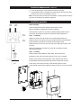
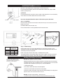
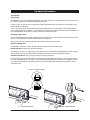
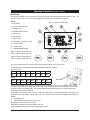
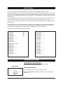
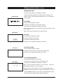
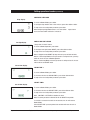
Installation and Operating Instructions
®
Zip Hydroboil Electronic
Large boiling water
Affix Model Number Label Here
89956
Zip Hydroboil Electronic - Installation & Operating Instructions - 89956 - May 2012 v1.06
Page 1 of 16
This page intentionally left blank
Page 2 of 16
Zip Hydroboil Electronic - Installation & Operating Instructions - 89956 - May 2012 v1.06
Contents
Read these warnings first . . . . . . . . . . . . . . . 4
Installation Requirements . . . . . . . . . . . . . . . 4 , 5
Installation Procedures . . . . . . . . . . . . . . . . . 5 - 7
Step 1 – Positioning . . . . . . . . . . . . . . . 5
Step 2 – Fastening . . . . . . . . . . . . . . . . 5
See page 6, Wall Mounting Template Dimensions
Step 3 – Connecting . . . . . . . . . . . . . . . 6
a) Plumbing. . . . . . . . . . . . . . . . 6
b) Venting . . . . . . . . . . . . . . . . . 6 , 7
c) Electrical . . . . . . . . . . . . . . . . 7
Step 4 – Assembling . . . . . . . . . . . . . . . 7
Step 5 – Commissioning . . . . . . . . . . . 7
Earthing Continuity Verification . . . . . . . . . . . 7
Tap Operating Procedures . . . . . . . . . . . . . . . 8
Operational Procedure Settings . . . . . . . . . . . 10
Default Settings . . . . . . . . . . . . . . . . . . . . . . . 10
Setting Operational Modes. . . . . . . . . . . . . . . 10 - 12
Normal Mode. . . . . . . . . . . . . . . . . . . . . . . . . 10
Configurational mode. . . . . . . . . . . . . . . . . . . 11
Problem Solving. . . . . . . . . . . . . . . . . . . . . . . 13
End of life disposal . . . . . . . . . . . . . . . . . . . . 13
Spare Parts . . . . . . . . . . . . . . . . . . . . . . . . . . 14, 15
Contact Details . . . . . . . . . . . . . . . . . . . . . . . 16
Note:
Read all instructions and precautions before proceeding. This unit must be
installed in accordance with water supply by-laws and relevant local authority
by-laws.
All plumbing must comply with AS3500.4.1 & AS3500.4
All electrical must comply with AS/NZS3000
Page 3 of 16
Zip Hydroboil Electronic - Installation & Operating Instructions - 89956 - May 2012 v1.06
Read These Warnings First
Please read all installation requirements, installation procedures and precautions before
installing any Zip Hydroboil instant boiling water heater.
Never attempt to install any Zip Hydroboil instant boiling water heater without reading all of
the applicable instructions.
In some hard water areas where mineral scale accumulation in the boiling chamber of the
Zip Hydroboil may become a problem, consideration should be given to the maintenance
required. A suitable form of water treatment may be necessary.
All plumbing connections must be made in accordance with local regulations.
The Zip Hydroboil instant boiling water heater is not intended for use by persons (including
children) with reduced physical, sensory or mental capabilities, or lack of experience and
knowledge, unless they have been given supervision or instruction concerning use of the
appliance by a person responsible for their safety.
Children should be supervised to ensure that they do not play with the appliance.
Young children should be prevented from having access to ensure that they are not able to
use or play with the heater.
If the installation site is located more than 1000 metres above sea level, the installer should
contact a Zip authorised agent for high altitude settings.
This appliance must be earthed. If the power supply cable is damaged it must be replaced
by a Zip authorised agent or a qualified electrician.
Do not remove the cover of the heater under any circumstances without first isolating the
heater from the power supply.
Do not use strong, corrosive or abrasive cleaners to clean the case of the heater.
Frost protection: If this heater is located where ambient air temperature could fall below 5ºC
when the heater is not in use, do not turn off the appliance electrically. This safeguard does
not offer the same protection to the connecting pipework and fittings.
This heater is intended only for indoor use and should never be installed outdoors or be
exposed to the elements of nature.
This unit must not be positioned in an area that may be cleaned by a water jet. This unit
must not be cleaned by a water jet.
Installation Requirements
Before installing, ensure that the following are available:
a) Sufficient space to position the heater so there is at least 150 mm
clearance above the heater for service access, 65 mm to its left and
20 mm to its right – the tap outlet usually should be positioned at least
200 mm above a draining board or drip tray.
b) Standard local requirement power cable positioned as shown on the paper mounting
template for connection from the rear of the heater to the terminal block within the heater,
this will require an isolating switch fitted in the fixed wiring and attached to a secure
surface. This switch must provide all pole disconnection and a contact seperation of at least
3mm installed in accordance with the wiring rules. Alternatively a standard 220-240V, 10
amp general purpose outlet, within 1500 mm of the Hydroboil Unit.
c) Cold water supply with a minimum working pressure of 70 kpa and a maximum
working pressure of 700 kpa connected via an isolation valve.
d) Outlet drainage to a sink draining board or to a drip tray.
Page 4 of 16
Zip Hydroboil Electronic - Installation & Operating Instructions - 89956 - May 2012 v1.06
Installation Requirements (continued)
e) Access to drainage from a vent situated at the base of the heater.
f) In all installation instances the walls of the heater must be vertical and the base
horizontal, there can be no exceptions to this rule.
Note: If the water pressure is likely to exceed 700 kpa, a 350 kpa pressure reducing
valve must be installed in the cold water supply line.
Installation procedure
VENT
OUTLET
COLD
INLET
Before You Begin
Locate the paper mounting-hole template packed with the heater.
Read the installation and operating instructions completely.
Decide whether to install with concealed or exposed plumbing and/or electrical
connections. Concealed connections are preferred for superior appearance.
INLET
POSITION
Step 1 – Positioning
Position the heater so the tap will drain on to a draining board or drip tray.
VENT
POSITION
Position the base of the tap to be not less than 200 mm above the draining board
(height should be increased only if essential for filling larger vessels).
Provide clearance for service access of not less than 150 mm top, 65 mm left, 20
mm right.
Mark corner positions for the heater on the wall so as to position the paper
mounting-hole template.
45mm
Step 2 – Fastening
Position mounting-hole template on wall and drill holes where shown.
Drill holes for water inlet, vent outlet and wiring if rear access is intended.
Remove cover fastening screws from heater and lift whole cover off heater.
Install plumbing and wiring and prepare pipe ends and wiring ends as shown.
Screw heater chassis to the wall using screws or bolts suited to the wall.
Elbow
Screws or bolts must be able to support the weight as shown in the chart on the left.
40 Litre ONLY
Page 5 of 16
Zip Hydroboil Electronic - Installation & Operating Instructions - 89956 - May 2012 v1.06
Installation Procedures (continued)
Wall template for 15, 25 & 40 litre models
374 (15L, 25L)
499 (40L)
295 (15L, 25L)
420 (40L)
591 (15L)
771 (25L)
831 (40L)
188 (15L, 25L)
313 (40L)
Step 3 – Connecting
a) Plumbing
Aprox weight when filled
15 Litre models
25 Litre models
40 Litre models
For exposed plumbing connection, connect the cold water inlet pipe from the base of the heater directly
to the 15 mm or half-inch compression fittings with the nuts and olives provided.
34.5 kg
47 kg
71 kg
For concealed plumbing connections, connect the cold water pipe through the rear of the chassis using
a 15 mm or half-inch capillary elbow.
Cold water pipes must be flushed before connection to the inlet. Any clogging due to sediment or fines
will adversely affect the operation of the heater.
The heater must be installed with an isolating valve which allows it to be isolated from the mains
supply for servicing.
250mm
Wring
45 mm
Water pressure requirements:
Minimum - 70 kpa, maximum - 700 kpa.
Concealed
Inlet
Concealed
Vent
Warning: If pressure is likely to exceed 700 kpa, a pressure limiting valve must be installed in the cold
water supply line. Zip recommends a valve rated at 350 kpa for this application.
b) Venting
A vent at the base of the heater must be plumbed to a safe visible location as, under certain
conditions, it may discharge cold or boiling water and/or steam.
For exposed vent plumbing, connect vent outlet from the base of heater to a
15 mm or half inch OD pipe which has a continuous fall, is no more than 3 metres long, has no
Page 6 of 16
Zip Hydroboil Electronic - Installation & Operating Instructions - 89956 - May 2012 v1.06
Installation Procedures (continued)
more than 3 right angle bends, and discharges to a waste water drain.
For concealed vent plumbing, direct the vent outlet from the heater rear, using a visible
tundish. (see diag at left)
c) Electrical
For concealed electrical connection, connect a power cable through the rear access opening
of the heater to the terminal block within the heater as shown.
Vent line
Visible Tundish
Do not turn the power ON until the heater is filled to the tap level, with water.
Step 4 – Assembling
Place the heater case back on to the heater and secure the top 2 case screws. Secure two
bottom case screws.
Insert Outlet Nozzle into the heater case.
Ensure the outlet tube is correctly positioned within the outlet nozzle.
Model
15 Litre
25 Litre
40 Litre
Inlet Water
Temperature
15°C
10°C
40 min 43 min
47 min 50 min
60 min 64 min
Step 5 - Commissioning
Check previous steps. Turn water supply ON. Water is now flowing into heater, check
connections for leaks. Wait approximately 5 minutes and check outlet tap for water. This is
achieved by pressing the tap paddle.
Power is only to be turned on when water is available from this outlet.
Turn power ON. After a short period, boiling water will be available and will be maintained
close to boiling point thereafter. Initial heating periods are shown in the table on the left.
Earthing Continuity Verification
If required, an earth continuity test can be
performed by testing between the earth wire
on the product’s lead and a exposed piece of
metal on the case and the tap body.
Warning: this appliance must be earthed.
Following remedial service the earthing continuity of the heater must be checked by
a qualified technician using an appliance tester, or continuity tester of accuracy Class
5 or better. Class 5 denotes an accuracy of 5% full scale deflection.
1. Isolate power supply.
2. Set meter to 0 ohm with leads connected together.
3. Connect one test lead to the earth wire on the product.
4. Connect the other test lead to a bare patch of metal (preferably on the edge) of the
top of the cover, then to the front cover of the unit.
Warning- the water may be boiling - show extra care.
5. Test that in every instance the electrical resistance does not exceed 1 ohm.
Page 7 of 16
Zip Hydroboil Electronic - Installation & Operating Instructions - 89956 - May 2012 v1.06
Tap Operating Procedures
Tap Operation
Safety feature.
Zip Hydroboil has a unique safety device designed to reduce the incidence of accidental operation of the tap.The tap can
be “Locked” to prevent the Hydroboil from dispensing hot water
In order to “lock” the tap, ensure the safety button is protruding from the right hand side of the control panel and the
locked indicator is illuminated
This can be achieved by pressing the button and simultaneously rotating it until the groove in the head of the button
faces toward the body of the appliance. In this position an internal spring will push the button out. Once the button is in
the extended position, the tap will be “Locked” and unable to dispense hot water.
Disengage safety feature.
Press and simultaneously rotate (aprox 90 degrees) the safety button on the right hand side of the control panel, until it
latches in the closed position, and the unlocked indicator is illuminated.
Warning: The unit is now capable of dispensing boiling water without the safety feature.
Dispensing Boiling water:
Zip Hydroboil is fitted with a safety, two-way cool-touch safety tap for instant boiling water.
Normal operation (for filling cups and small containers)
To activate the tap, press the safety button on the right side of the control panel and while holding the button in, gently
push the lower end of the tap paddle inwards and boiling water will flow until the tap paddle is released.
Continuous operation (for filling, tea pots, saucepans and large containers )
Press the safety button on the right side of the control panel and while holding the button in, Lift the tap paddle until it
locks into a horizontal position, the button can now be released and boiling water will flow until the paddle is returned
to its normal vertical position. This operation allows a vessel to be filled without holding your hand where it may be
affected by steam.
Locked / unlocked indicators
locke
d
Press
Continuous operation
Page 8 of 16
to unl
ock
Press
Normal operation
Zip Hydroboil Electronic - Installation & Operating Instructions - 89956 - May 2012 v1.06
to unl
ock
Operating Procedures (setting the controls)
DESCRIPTION
The Electronic Hydroboil has user interface that consists of a graphic LCD and 4 Capacitive Sensor Switches, (CSS). The
user interface gives the current status of the Hydroboil and allows the user to configure it as required.
Legend:
The user interface is shown below.
1 = ZIP Symbol
2 = Day of the Week indicator
4
3
3 = Setpoint Value
5
6
2
4 = CHANGE FILTER indicator
7
5 = ON indicator
6 = OFF indicator
7 = Sleep Symbol
1
8 = Sleep mode ( Stand by ) indicator
9 = Low light Symbol
SUN
MON
TUE
WED
THU
FRI
SAT
CHANGE FILTER
SETPOINT
C
11
10
ON
OFF
8
BOILING WATER
zZ
Z
10 = 24hour Clock
11 = BOILING WATER indicator
CSS1 = Capacitive Sensor Switch 1
9
CSS2 = Capacitive Sensor Switch 2
CSS3 = Capacitive Sensor Switch 3
CSS4 = Capacitive Sensor Switch 4
CSS1
CSS3
CSS2
CSS4
The LCD and capacitive sensor switches connect to the Controller PCB via a 4-way serial cable.
The DIP Switches on the Controller PCB assembly should be configured as follows.
15 Litre & 25 Litre
SW1
SW2
SW3
SW4
SW5
SW6
SW7
SW8
ON
ON
OFF
ON
OFF
ON
ON
ON
SW1
SW2
SW3
SW4
SW5
SW6
SW7
SW8
ON
ON
OFF
OFF
OFF
ON
ON
ON
40 Litre
DIP Switches
The Electronic Hydroboil has a real time clock that operates in 24 hour mode, and can have 2 ON-OFF times per day.
If the user selects either of the energy saver modes, (see below), ON-OFF mode cannot be used, (The user is not able
to access this part of the configuration). The real time clock is battery backed meaning the unit does not loose the
configuration data if power is removed.
The Hydroboil has two energy saver ( stand by ) modes that can be used in an either/or configuration. The energy saver
modes differ from on/off mode in that the water in the tank is maintained at 65ºC rather than allowing it to drift back to
ambient.
1) Sleep Mode, and
2) Low Light Mode. (Sleep-when-it’s-dark feature)
Sleep Mode can be set to 2 hours or 4 hours.
Sleep Mode is indicated by the Sleep symbol on the LCD.
Low Light Mode is indicated by the Low Light symbol on the LCD.
Page 9 of 16
Zip Hydroboil Electronic - Installation & Operating Instructions - 89956 - May 2012 v1.06
Default settings
When the unit actually enters energy saver mode it is indicated by the Sleep Mode Indicator on the LCD.
In 2 Hour Sleep Mode, if there has been no water drawn through the tap or no touches of the capacitive switch sensors
for two hours, the temperature of the water in the tank will be allowed to drop to and be maintained at 65ºC. (The time
taken for the water temperature to drop to 65ºC can be as much as 12 hours depending on ambient conditions and other
external factors).
In 4 Hour Sleep Mode, if there has been no water drawn through the tap or no touches of the capacitive switch sensors
for four hours, the temperature of the water in the tank will be allowed to drop to and be maintained at 65ºC.
As soon as water is drawn through the tap, or there is a touch on the capacitive switch sensors, the Hydroboil returns to
full power mode.
In Low Light Mode, as soon as the ambient light (in the room where the Hydroboil is installed ) drops below 100lux, the
unit goes into energy saver mode and will allow the temperature of the stored water to drop to and be maintained at
65ºC. As soon as the ambient light rises above 100lux, the Hydroboil returns to full power mode.
A normal office has an ambient light level of 200-300lux.
TEMPERATURE SETPOINT:
FILTER TIMER:
SLEEP MODE:
LOW LIGHT MODE:
SUN ON TIME 1: --:-SUN OFF TIME 1: --:-SUN ON TIME 2: --:-SUN OFF TIME 2: --:-MON ON TIME 1: 08:00
MON OFF TIME 1: --:-MON ON TIME 2: --:-MON OFF TIME 2: --:-TUE ON TIME 1: --:-TUE OFF TIME 1: --:-TUE ON TIME 2: --:-TUE OFF TIME 2: --:--
98ºC
OFF
OFF
OFF
WED ON TIME 1:
WED OFF TIME 1:
WED ON TIME 2:
WED OFF TIME 2:
THU ON TIME 1:
THU OFF TIME 1:
THU ON TIME 2:
THU OFF TIME 2:
FRI ON TIME 1:
FRI OFF TIME 1:
FRI ON TIME 2:
FRI OFF TIME 2:
SAT ON TIME 1:
SAT OFF TIME 1:
SAT ON TIME 2:
SAT OFF TIME 2:
--:---:---:---:---:---:---:---:---:---:---:---:---:---:---:---:--
Setting operational modes
The Hydroboil has 2 modes of operation:
1).Normal operation mode
2). Configuration mode
Normal display
Normal operation mode
In Normal operation mode the LCD will display as follows:
Note: The BOILING WATER symbol is not displayed until the water reaches
temperature.
Page 10 of 16
Zip Hydroboil Electronic - Installation & Operating Instructions - 89956 - May 2012 v1.06
Setting operational modes (continued)
Configuration mode
The Default configuration for the Hydroboil is as follows.
tting operational modes
Setpoint display
To enter Configuration Mode, press and hold the CSS1 and CSS4 for 10
seconds. The unit enters Configuration Mode and the user can configure the
clock as follows.
SET SETPOINT
To return to Normal Mode, press CSS4.
To increment the setpoint, press either CSS2 or CSS3.
To step to the next configuration parameter, press CSS1.
Note 1: The setpoint moves in a circular fashion. It goes from 98 to 99 to 100
to 65 to 66 etc.
Note 2: 100ºC may be indicated by 1H or 100 on the LCD
Clock display
SET CLOCK
To return to Normal Mode, press CSS4.
To increment the Hours, press CSS2.
To increment the Minutes, press CSS3.
To step to the next configuration parameter, press CSS1.
SET DAY-OF-THE-WEEK
Day display
To return to Normal Mode, press CSS4.
To step to the next day of the week, press either CSS2 or CSS3.
To step to the next configuration parameter, press CSS1.
SET FILTER EXPIRATION TIME
To return to Normal Operation, press CSS4.
Filter display
To increment the expiration time, press either CSS2 or CSS3.
To step to the next configuration parameter, press CSS1.
Note 1: The Filter expiration time moves in a circular fashion. It goes from
OFF to 00 to 01 to 02 etc, etc. up to 14 months.
Note 2: 00 is a test mode. When the user returns to Normal Operation, the
CHANGE FILTER icon will appear on the LCD after approximately 1minute. To
clear the CHANGE FILTER icon, the user must re-enter Configuration, set the
Filter Expiration Time to OFF and return to Normal Operation.
Page 11 of 16
Zip Hydroboil Electronic - Installation & Operating Instructions - 89956 - May 2012 v1.06
Setting operational modes (continued)
CONFIGURE SLEEP MODE
perational
modes
Sleep display
To return to Normal Mode, press CSS4.
To configure sleep mode to kick in after 4 hours, press either CSS2 or CSS3.
To step to the next configuration parameter, press CSS1.
Note: Configuring Sleep Mode moves in a circular fashion. It goes from 2
hours to 4 hours to OFF and back to 2 hours etc.
Low light display
ENABLE LOW LIGHT SENSOR
“Sleep-when-it’s-dark” feature.
To return to Normal Operation, press CSS4.
To configure Low Light Sensor ON/OFF, press either CSS2 or CSS3.
To step to the next configuration parameter, press CSS1.
Note 1: Daylight Sensor ON/OFF flip flops with each press of CSS2 or CSS3.
Note 2: If either Sleep Mode or Low Light sensor is configured as on, pressing
CSS1 will return the user to Normal Operation.
Note 3: If both Sleep Mode and Low Light sensor is configured as off, the user
will be able to use ON-OFF mode.
Sun on-time display
SUN ON-TIME 1
To return to Normal Mode, press CSS4.
To increment the hour for SUN ON-TIME 1, press either CSS2 or CSS3.
To step to the next configuration parameter, press CSS1.
SUN OFF-TIME 1
Sun off-time display
To return to Normal Mode, press CSS4.
To increment the hour for SUN OFF-TIME1, press either CSS2 or CSS3.
To step to the next configuration parameter, press CSS1.
Note: If ON TIME = OFF TIME this disables the timer.
Note: The same procedure is followed for all the ON-OFF time periods.
If no action is sensed on the CSS’s for 20 seconds, the unit will revert to
Normal Mode.
After SAT OFF-TIME 2 pressing either CSS1 or CSS4 will revert the unit to
Normal Mode.
Page 12 of 16
Zip Hydroboil Electronic - Installation & Operating Instructions - 89956 - May 2012 v1.06
Problem Solving
Sympton
Possible Cause
Solution
Fails to dispense water.
Water isolating valve turned off.
Blocked filter, blocked meter tube,
blocked strainer, jammed ball
valve assy, airlock in transfer tube.
Incorrectly positioned outlet tube.
Check water supply valve.
Reposition silicon outlet tube in outlet
nozzle.
Contact Zip authorised agent.
No power.
Water not boiling.
Runs out of boiling water and fails to
refill.
Outlet tap drips.
Overflow from vent.
Excessive steam from vent.
Power “on” but no heat.
Overload repeatedly tripping with
excessive steam.
Overload repeatedly tripping without
excessive steam.
Check power supply.
Faulty PCB, faulty NTC, faulty element,
faulty cutout.
Contact Zip authorised agent.
Internal adjustment.
Contact Zip athorised agent.
End of life Disposal
In order to help preserve our environment we ask that you dispose of this
product correctly. Please contact your local city council for collection centre
details
Page 13 of 16
Zip Hydroboil Electronic - Installation & Operating Instructions - 89956 - May 2012 v1.06
Spare Parts
Key
1
2
3
4
5
6
7
8
9
10
11
12
13
13
14
15
16
17
18
19
19
19
20
21
22
23
24
24
Page 14 of 16
Kit No. Description
90096
90140
90120
90490
90121
90083
90069
90496
90102
90495
90174
90743
90994
90995
90620
90733
90509
90492
90214
90123
90125
90124
90996
90732
90997
90998
90531
90526
Cistern Lid Clamp Kit
Overload Kit
Disc, Capsule, Lid, Gasket Kit
Gasket Kit
Cistern Lid Gasket
Float Valve Kit
Jumper Valve Kit
O-Ring Kit
Cistern Float S/Nut Kit
Banjo Screw Kit
Contactor Kit
Fascia Lens
Fascia Assy Electronic White
Fascia Assy Electronic Grey
Sensor Probe Hot Tank
Outlet Nozzle
Tap Bidy Kit
Drain & Cap Seal Kit
Sensor Sleep Mode
Element 2400w / 240v
Element 3000w / 240v
Element 3600w / 240v
Front Insulation
Tap Handle Kit
Cap Drain Sensor Assy Kit
PCB Kit
Metering Tube Kit 3000w
Metering Tube Kit 6000w
Zip Hydroboil Electronic - Installation & Operating Instructions - 89956 - May 2012 v1.06
Spare Parts
&RQQHFWRU21/<
Contactor
Only for 40L
IRU/
'(7$,/&RQQHFWRU
6&$/(
Page 15 of 16
Zip Hydroboil Electronic - Installation & Operating Instructions - 89956 - May 2012 v1.06
Contact Details
Head Office
Zip Heaters (Aust) Pty. Ltd.
ABN 46 000 578 727
67 Allingham Street
Condell Park NSW 2200
Postal: Locked Bag 80
Bankstown 1885 Australia
WMKA00099
AS 3498
Website: www.zipheaters.com
Facsimile (02) 9796 3858
Telephone (02) 9796 3100
Free Call 1 800 638 633
As Zip policy is one of continuous product improvement, changes to
specifications may be made without prior notice. Images in this booklet have
been modified and may not be true representations of the finished goods.
Page 16 of 16
Zip Hydroboil Electronic - Installation & Operating Instructions - 89956 - May 2012 v1.06