1
Elisys Duo
#
| User Manual
HUMAN ELISYS DUO
User Manual
|
C a t.No. 17 2 0 0/ 1
Edition:
Rev. /DATE.
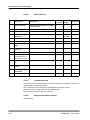
REVISION DESCRIPTION
01/2008-12
First edition
02/2010-11
Update page 1-1 "Intendend Use", new cover and back page
System:
Manufacturer:
HUMAN Gesellschaft für Biochemica und Diagnostica mbH
Software-copyrights
The Elisys Duo software is the intellectual property of HUMAN GmbH.
Intellectual property rights shall remain with HUMAN GmbH
You are entitled to use the Elisys Duo software and the printed accompanying material at your place of work only.
Any violations of property rights or copyright or trademark may be subject to legal
action.
Copyright © 2010, HUMAN GmbH. All rights reserved.
HUMAN Gesellschaft für Biochemica und Diagnostica mbH
Max-Planck-Ring 21
D-65205 Wiesbaden, GERMANY
Neither this manual nor any parts of it may be duplicated or transmitted in any way without the written
approval of HUMAN GmbH.
We reserve the right to make changes in the course of technical development
without previous notice.
Elisys Duo - User Manual
1-3
1-4
Elisys Duo - User Manual
Table of Contents
1
Introduction . . . . . . . . . . . . . . . . . . . . . . . . . . . . . . . . . . . . . 1-1
1.1
1.2
Intended Use . . . . . . . . . . . . . . . . . . . . . . . . . . . . . . . . . . . . . . . . . 1-1
Typographical Conventions . . . . . . . . . . . . . . . . . . . . . . . . . . . . . 1-2
1.2.1 Warning Messages . . . . . . . . . . . . . . . . . . . . . . . . . . . . . . . . . . . 1-2
1.2.2 Notes . . . . . . . . . . . . . . . . . . . . . . . . . . . . . . . . . . . . . . . . . . . . . 1-3
1.2.3 Symbol Keys. . . . . . . . . . . . . . . . . . . . . . . . . . . . . . . . . . . . . . . . 1-3
1.2.4 Special Types . . . . . . . . . . . . . . . . . . . . . . . . . . . . . . . . . . . . . . . 1-4
1.2.5 Abbreviations . . . . . . . . . . . . . . . . . . . . . . . . . . . . . . . . . . . . . . . 1-5
1.3 Safety Instructions. . . . . . . . . . . . . . . . . . . . . . . . . . . . . . . . . . . . . 1-7
1.3.1 General Safety . . . . . . . . . . . . . . . . . . . . . . . . . . . . . . . . . . . . . . 1-7
1.3.2 Electrical Safety . . . . . . . . . . . . . . . . . . . . . . . . . . . . . . . . . . . . . 1-8
1.3.3 Laser Safety . . . . . . . . . . . . . . . . . . . . . . . . . . . . . . . . . . . . . . . . 1-9
1.3.4 Mechanical Safety . . . . . . . . . . . . . . . . . . . . . . . . . . . . . . . . . . 1-10
1.3.5 Biological Safety . . . . . . . . . . . . . . . . . . . . . . . . . . . . . . . . . . . . 1-10
1.3.6 Touch Screen Handling and Cleaning . . . . . . . . . . . . . . . . . . . 1-11
1.3.7 Cleaning the System. . . . . . . . . . . . . . . . . . . . . . . . . . . . . . . . . 1-11
1.3.8 Disposal . . . . . . . . . . . . . . . . . . . . . . . . . . . . . . . . . . . . . . . . . . 1-11
1.4 Positions of Safety Labels and Type Label . . . . . . . . . . . . . . . . 1-13
1.4.1 General Warning Labels . . . . . . . . . . . . . . . . . . . . . . . . . . . . . . 1-13
1.4.2 Biological Hazard Labels . . . . . . . . . . . . . . . . . . . . . . . . . . . . . 1-13
1.4.3 Electrical Hazard Labels . . . . . . . . . . . . . . . . . . . . . . . . . . . . . . 1-13
1.4.4 Laser Hazard Labels. . . . . . . . . . . . . . . . . . . . . . . . . . . . . . . . . 1-13
1.4.5 Type Label . . . . . . . . . . . . . . . . . . . . . . . . . . . . . . . . . . . . . . . . 1-13
2
System Description . . . . . . . . . . . . . . . . . . . . . . . . . . . . . . . 2-1
2.1
System Overview . . . . . . . . . . . . . . . . . . . . . . . . . . . . . . . . . . . . . . 2-2
2.1.1 System . . . . . . . . . . . . . . . . . . . . . . . . . . . . . . . . . . . . . . . . . . . . 2-2
2.1.2 Instrument Modules . . . . . . . . . . . . . . . . . . . . . . . . . . . . . . . . . . 2-3
2.1.3 Liquid Connections . . . . . . . . . . . . . . . . . . . . . . . . . . . . . . . . . . . 2-4
2.1.4 Electrical Connections . . . . . . . . . . . . . . . . . . . . . . . . . . . . . . . . 2-6
2.2 Use of the Modules . . . . . . . . . . . . . . . . . . . . . . . . . . . . . . . . . . . . 2-7
2.2.1 Microplates in the Plate Transport . . . . . . . . . . . . . . . . . . . . . . . 2-7
2.2.2 Disposable Tip Racks . . . . . . . . . . . . . . . . . . . . . . . . . . . . . . . . . 2-9
2.2.3 Dilution or Archive Plates . . . . . . . . . . . . . . . . . . . . . . . . . . . . . 2-10
2.2.4 Rack System for Samples and Reagents . . . . . . . . . . . . . . . . . 2-12
2.2.5 Washer and Wash Buffers . . . . . . . . . . . . . . . . . . . . . . . . . . . . 2-14
2.2.6 Incubator and Stacker. . . . . . . . . . . . . . . . . . . . . . . . . . . . . . . . 2-14
2.2.7 Photometer . . . . . . . . . . . . . . . . . . . . . . . . . . . . . . . . . . . . . . . . 2-14
2.2.8 Pipettor and Dispense Pump . . . . . . . . . . . . . . . . . . . . . . . . . . 2-15
2.2.9 Touch Screen . . . . . . . . . . . . . . . . . . . . . . . . . . . . . . . . . . . . . . 2-17
2.3 Accessories and Consumables . . . . . . . . . . . . . . . . . . . . . . . . . 2-18
2.4 Principles of Methods . . . . . . . . . . . . . . . . . . . . . . . . . . . . . . . . . 2-19
2.4.1 Absorbance Photometry . . . . . . . . . . . . . . . . . . . . . . . . . . . . . . 2-19
2.4.2 Bichromatic Measurement . . . . . . . . . . . . . . . . . . . . . . . . . . . . 2-19
3
Basic Functions . . . . . . . . . . . . . . . . . . . . . . . . . . . . . . . . . . 3-1
3.1
Elisys Duo - User Manual
Menus and Symbols . . . . . . . . . . . . . . . . . . . . . . . . . . . . . . . . . . . 3-1
3.1.1 General Functions . . . . . . . . . . . . . . . . . . . . . . . . . . . . . . . . . . . 3-1
3.1.2 Functions of the Menu and Selection Dialog F i l e . . . . . . . . . . . 3-3
3.1.3 Functions of the Menu E d i t3-5
TOC-1
3.1.4 Functions of the Menu and Selection Dialog U t i l i t i e s . . . . . . . 3-6
3.1.5 Functions of the Menu and Selection Dialog W i n d o w s . . . . . 3-8
3.1.6 Functions of the Menu and Selection Dialog H e l p . . . . . . . . . . 3-9
3.2 New. . . . . . . . . . . . . . . . . . . . . . . . . . . . . . . . . . . . . . . . . . . . . . . . . 3-10
3.2.1 Functions of the Selection Dialog New . . . . . . . . . . . . . . . . . . 3-10
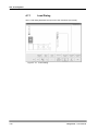
3.3 Load (Open). . . . . . . . . . . . . . . . . . . . . . . . . . . . . . . . . . . . . . . . . . 3-11
3.3.1 Functions of the Selection Dialog O p e n . . . . . . . . . . . . . . . . . 3-11
3.3.2 Open a File . . . . . . . . . . . . . . . . . . . . . . . . . . . . . . . . . . . . . . . . 3-11
3.4 Save . . . . . . . . . . . . . . . . . . . . . . . . . . . . . . . . . . . . . . . . . . . . . . . . 3-14
3.5 Print on the Printer . . . . . . . . . . . . . . . . . . . . . . . . . . . . . . . . . . . . 3-16
3.5.1 Print . . . . . . . . . . . . . . . . . . . . . . . . . . . . . . . . . . . . . . . . . . . . . . 3-16
3.5.2 Print Setup . . . . . . . . . . . . . . . . . . . . . . . . . . . . . . . . . . . . . . . . . 3-18
3.5.3 Print Preview . . . . . . . . . . . . . . . . . . . . . . . . . . . . . . . . . . . . . . . 3-20
3.6 Edit and Selection Dialogs. . . . . . . . . . . . . . . . . . . . . . . . . . . . . . 3-21
3.6.1 E d i t T e x t Dialog . . . . . . . . . . . . . . . . . . . . . . . . . . . . . . . . . . 3-21
3.6.2 E d i t a N u m b e r Dialog . . . . . . . . . . . . . . . . . . . . . . . . . . . . 3-23
3.6.3 Selection Dialog . . . . . . . . . . . . . . . . . . . . . . . . . . . . . . . . . . . . . 3-24
4
Use of the System . . . . . . . . . . . . . . . . . . . . . . . . . . . . . . . . 4-1
4.1
4.2
4.3
Brief Sequence Plan . . . . . . . . . . . . . . . . . . . . . . . . . . . . . . . . . . . . 4-2
Start-up . . . . . . . . . . . . . . . . . . . . . . . . . . . . . . . . . . . . . . . . . . . . . . 4-3
Load Samples and Assign Assays . . . . . . . . . . . . . . . . . . . . . . . . 4-5
4.3.1 Load Samples . . . . . . . . . . . . . . . . . . . . . . . . . . . . . . . . . . . . . . . 4-5
4.3.2 Assign Assays to the Samples (Tabular P a t i e n t E d i t o r) . . . 4-6
4.3.3 Import Patient Data and Linked Assays through Host Connection 49
4.4 Create a Worklist. . . . . . . . . . . . . . . . . . . . . . . . . . . . . . . . . . . . . . 4-10
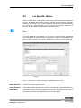
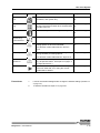
4.5 Lot Specific Values . . . . . . . . . . . . . . . . . . . . . . . . . . . . . . . . . . . . 4-11
4.6 The Worklist Window . . . . . . . . . . . . . . . . . . . . . . . . . . . . . . . . . . 4-14
4.6.1 Worklist Parameters. . . . . . . . . . . . . . . . . . . . . . . . . . . . . . . . . . 4-16
4.6.2 Schedule . . . . . . . . . . . . . . . . . . . . . . . . . . . . . . . . . . . . . . . . . . 4-17
4.6.3 Plate Layouts . . . . . . . . . . . . . . . . . . . . . . . . . . . . . . . . . . . . . . . 4-19
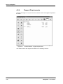
4.6.4 Reagent Requirements . . . . . . . . . . . . . . . . . . . . . . . . . . . . . . . 4-20
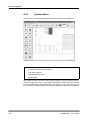
4.6.5 System Status . . . . . . . . . . . . . . . . . . . . . . . . . . . . . . . . . . . . . . 4-22
4.6.6 Active Event Log . . . . . . . . . . . . . . . . . . . . . . . . . . . . . . . . . . . . 4-23
4.6.7 Job List . . . . . . . . . . . . . . . . . . . . . . . . . . . . . . . . . . . . . . . . . . . 4-27
4.6.8 Sample Archiving Information . . . . . . . . . . . . . . . . . . . . . . . . . . 4-27
4.7 Start Worklist. . . . . . . . . . . . . . . . . . . . . . . . . . . . . . . . . . . . . . . . . 4-28
4.7.1 Load Dialog . . . . . . . . . . . . . . . . . . . . . . . . . . . . . . . . . . . . . . . . 4-30
4.7.2 Load Samples . . . . . . . . . . . . . . . . . . . . . . . . . . . . . . . . . . . . . . 4-34
4.7.3 Load Reagents. . . . . . . . . . . . . . . . . . . . . . . . . . . . . . . . . . . . . . 4-36
4.7.4 Load Unstable Reagents . . . . . . . . . . . . . . . . . . . . . . . . . . . . . . 4-39
4.7.5 Load Dilution Plates . . . . . . . . . . . . . . . . . . . . . . . . . . . . . . . . . . 4-41
4.7.6 Load Tip Racks . . . . . . . . . . . . . . . . . . . . . . . . . . . . . . . . . . . . . 4-42
4.7.7 Fill Wash Buffer and Clean Fluid . . . . . . . . . . . . . . . . . . . . . . . . 4-45
4.7.8 Fill System Liquid. . . . . . . . . . . . . . . . . . . . . . . . . . . . . . . . . . . . 4-46
4.7.9 Load Test Plates . . . . . . . . . . . . . . . . . . . . . . . . . . . . . . . . . . . . 4-46
4.8 Processing the Run . . . . . . . . . . . . . . . . . . . . . . . . . . . . . . . . . . . 4-49
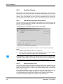
4.8.1 Pre-Run Checks . . . . . . . . . . . . . . . . . . . . . . . . . . . . . . . . . . . . 4-50
4.8.2 Steps of a Typical Test Run . . . . . . . . . . . . . . . . . . . . . . . . . . . . 4-53
4.8.3 What You Can Do While the Run is Being Processed . . . . . . . . 4-54
4.8.4 System/Pipetting Errors . . . . . . . . . . . . . . . . . . . . . . . . . . . . . . . 4-55
4.8.5 The System Paused Dialog . . . . . . . . . . . . . . . . . . . . . . . . . . . . 4-55
4.8.6 Pipetting Errors/Manual Pipetting . . . . . . . . . . . . . . . . . . . . . . . 4-57
4.8.7 Emergency Stop/Cancelling a Run . . . . . . . . . . . . . . . . . . . . . . 4-57
4.9 End of Run/Result Report Window . . . . . . . . . . . . . . . . . . . . . . . 4-58
4.9.1 Structure of the Result Report . . . . . . . . . . . . . . . . . . . . . . . . . . 4-60
TOC-2
Elisys Duo - User Manual
4.9.2 Result Interpretation . . . . . . . . . . . . . . . . . . . . . . . . . . . . . . . . .
4.9.3 Save/Open the Result Report. . . . . . . . . . . . . . . . . . . . . . . . . .
4.9.4 Print the Result Report . . . . . . . . . . . . . . . . . . . . . . . . . . . . . . .
4.9.5 Export the Results . . . . . . . . . . . . . . . . . . . . . . . . . . . . . . . . . .
4.10 Unloading . . . . . . . . . . . . . . . . . . . . . . . . . . . . . . . . . . . . . . . . . . .
4.10.1Unload Test Plates . . . . . . . . . . . . . . . . . . . . . . . . . . . . . . . . . .
4.10.2Unload Sample Racks . . . . . . . . . . . . . . . . . . . . . . . . . . . . . . .
4.10.3Unload Reagent Racks. . . . . . . . . . . . . . . . . . . . . . . . . . . . . . .
4.10.4Unload Tip Racks and Dilution Plates. . . . . . . . . . . . . . . . . . . .
4.10.5Unload Other Resources . . . . . . . . . . . . . . . . . . . . . . . . . . . . .
4.10.6Unload Waste Disposal. . . . . . . . . . . . . . . . . . . . . . . . . . . . . . .
4.11 Shut Down / End of Day Maintenance . . . . . . . . . . . . . . . . . . . .
5
4-61
4-65
4-65
4-66
4-67
4-67
4-69
4-69
4-70
4-70
4-70
4-71
Advanced Functions . . . . . . . . . . . . . . . . . . . . . . . . . . . . . . 5-1
5.1
Initialisation and Selftest. . . . . . . . . . . . . . . . . . . . . . . . . . . . . . . . 5-1
5.1.1 Manually Start Selftest . . . . . . . . . . . . . . . . . . . . . . . . . . . . . . . . 5-3
5.1.2 Selftest before each Run . . . . . . . . . . . . . . . . . . . . . . . . . . . . . . 5-3
5.1.3 Selftest Failures . . . . . . . . . . . . . . . . . . . . . . . . . . . . . . . . . . . . . 5-3
5.2 Complete P a t i e n t E d it o r . . . . . . . . . . . . . . . . . . . . . . . . . . . . . 5-4
5.2.1 Add new Patients . . . . . . . . . . . . . . . . . . . . . . . . . . . . . . . . . . . . 5-7
5.2.2 Edit Patient Details . . . . . . . . . . . . . . . . . . . . . . . . . . . . . . . . . . . 5-8
5.2.3 Assign Assays to the Samples (Complete Patient Editor) . . . . 5-10
5.2.4 Edit Assigned Assays . . . . . . . . . . . . . . . . . . . . . . . . . . . . . . . . 5-12
5.3 Create your own Worklist . . . . . . . . . . . . . . . . . . . . . . . . . . . . . . 5-13
5.3.1 Se t - u p P a n e l Dialog . . . . . . . . . . . . . . . . . . . . . . . . . . . . . 5-15
5.3.2 Add Patients . . . . . . . . . . . . . . . . . . . . . . . . . . . . . . . . . . . . . . . 5-19
5.3.3 Processing Several Assays per Plate. . . . . . . . . . . . . . . . . . . . 5-19
5.3.4 Save or Open a Worklist . . . . . . . . . . . . . . . . . . . . . . . . . . . . . . 5-23
5.4 Worklist Options . . . . . . . . . . . . . . . . . . . . . . . . . . . . . . . . . . . . . 5-24
5.4.1 Worklist Options: S c h e d u l i n g . . . . . . . . . . . . . . . . . . . . . . . 5-24
5.4.2 Worklist Options: B e f o r e Worklist will be started . . . . . . . . . 5-27
5.4.3 Worklist Options: D u r i n g Worklist is running . . . . . . . . . . . . 5-29
5.4.4 Worklist Options: A f t e r Worklist was finished . . . . . . . . . . . . 5-31
5.5 Advanced Options . . . . . . . . . . . . . . . . . . . . . . . . . . . . . . . . . . . . 5-32
5.5.1 Optimize the Schedule . . . . . . . . . . . . . . . . . . . . . . . . . . . . . . . 5-32
5.5.2 Advanced Load Options . . . . . . . . . . . . . . . . . . . . . . . . . . . . . . 5-33
5.5.3 Test Plate Removal. . . . . . . . . . . . . . . . . . . . . . . . . . . . . . . . . . 5-38
5.5.4 Editing/Recalculating the Results . . . . . . . . . . . . . . . . . . . . . . . 5-40
5.6 Continuous Loading . . . . . . . . . . . . . . . . . . . . . . . . . . . . . . . . . . 5-44
5.6.1 Check Reloading Time(s) . . . . . . . . . . . . . . . . . . . . . . . . . . . . . 5-45
5.6.2 Preparing and Loading the New Samples . . . . . . . . . . . . . . . . 5-46
5.6.3 Redefining the Worklist . . . . . . . . . . . . . . . . . . . . . . . . . . . . . . . 5-46
5.6.4 Reloading other Resources . . . . . . . . . . . . . . . . . . . . . . . . . . . 5-47
5.6.5 Reloading Test Plates and Further Processing of the Worklist . 5-47
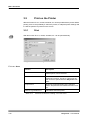
5.7 Patient Result Report . . . . . . . . . . . . . . . . . . . . . . . . . . . . . . . . . 5-48
5.7.1 Filter Configuration . . . . . . . . . . . . . . . . . . . . . . . . . . . . . . . . . . 5-51
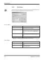
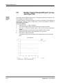
5.8 Quality Control Analysis Report (Levey Jennings Plot) . . . . . 5-52
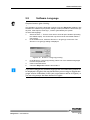
5.9 Software Language . . . . . . . . . . . . . . . . . . . . . . . . . . . . . . . . . . . 5-53
5.10 Simulation Mode / Demo Mode. . . . . . . . . . . . . . . . . . . . . . . . . . 5-54
6
Connection to a Host Computer. . . . . . . . . . . . . . . . . . . . . 6-1
6.1
ASCII File Transfer. . . . . . . . . . . . . . . . . . . . . . . . . . . . . . . . . . . . . 6-2
6.1.1 Hardware Configurations . . . . . . . . . . . . . . . . . . . . . . . . . . . . . . 6-2
6.1.2 Importing Patient Data and Worklist Files (Types of Import Files)6-3
6.1.3 Defining Import Parameters . . . . . . . . . . . . . . . . . . . . . . . . . . . . 6-5
6.1.4 Export of Test Results . . . . . . . . . . . . . . . . . . . . . . . . . . . . . . . . 6-11
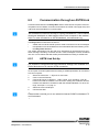
6.2 Communication through an ASTM Link . . . . . . . . . . . . . . . . . . 6-15
Elisys Duo - User Manual
TOC-3
6.2.1
6.2.2
6.2.3
6.2.4
6.2.5
7
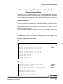
ASTM Link Set-Up . . . . . . . . . . . . . . . . . . . . . . . . . . . . . . . . . . . 6-15
Communication Procedure . . . . . . . . . . . . . . . . . . . . . . . . . . . . 6-16
Low-Level Protocol . . . . . . . . . . . . . . . . . . . . . . . . . . . . . . . . . . 6-17
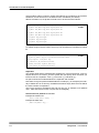
Logical Structure of the Message Level Protocol. . . . . . . . . . . . 6-18
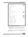
Incoming and Outgoing Transmission Examples. . . . . . . . . . . . 6-19
System Configuration . . . . . . . . . . . . . . . . . . . . . . . . . . . . . 7-1
7.1
System Options. . . . . . . . . . . . . . . . . . . . . . . . . . . . . . . . . . . . . . . . 7-1
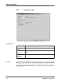
7.1.1 Access Control Tab . . . . . . . . . . . . . . . . . . . . . . . . . . . . . . . . . . . 7-1
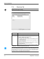
7.1.2 Preferences Tab. . . . . . . . . . . . . . . . . . . . . . . . . . . . . . . . . . . . . . 7-3
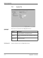
7.1.3 File Polling Tab . . . . . . . . . . . . . . . . . . . . . . . . . . . . . . . . . . . . . . 7-4
7.1.4 ASTM Tab . . . . . . . . . . . . . . . . . . . . . . . . . . . . . . . . . . . . . . . . . . 7-5
7.1.5 Laboratory Tab . . . . . . . . . . . . . . . . . . . . . . . . . . . . . . . . . . . . . . . 7-7
7.1.6 Directories Tab . . . . . . . . . . . . . . . . . . . . . . . . . . . . . . . . . . . . . . . 7-8
7.2 System Set-up . . . . . . . . . . . . . . . . . . . . . . . . . . . . . . . . . . . . . . . . 7-11
7.2.1 System Tab . . . . . . . . . . . . . . . . . . . . . . . . . . . . . . . . . . . . . . . . 7-12
7.2.2 Incubators Tab . . . . . . . . . . . . . . . . . . . . . . . . . . . . . . . . . . . . . . 7-14
7.2.3 Colorimeter Tab (Photometer) . . . . . . . . . . . . . . . . . . . . . . . . . . 7-16
7.2.4 Pipette Tab . . . . . . . . . . . . . . . . . . . . . . . . . . . . . . . . . . . . . . . . . 7-18
7.2.5 Sample Rack Tab. . . . . . . . . . . . . . . . . . . . . . . . . . . . . . . . . . . . 7-25
7.2.6 Washer Tab . . . . . . . . . . . . . . . . . . . . . . . . . . . . . . . . . . . . . . . . 7-29
7.2.7 Plate Transport Tab . . . . . . . . . . . . . . . . . . . . . . . . . . . . . . . . . . 7-33
7.2.8 Maintenance Tab . . . . . . . . . . . . . . . . . . . . . . . . . . . . . . . . . . . . 7-34
8
Maintenance and Cleaning . . . . . . . . . . . . . . . . . . . . . . . . . 8-1
8.1
8.2
Safety and Hints about Cleaning/Decontamination. . . . . . . . . . . 8-1
Daily Maintenance. . . . . . . . . . . . . . . . . . . . . . . . . . . . . . . . . . . . . . 8-3
8.2.1 Start-Up . . . . . . . . . . . . . . . . . . . . . . . . . . . . . . . . . . . . . . . . . . . . 8-3
8.2.2 After Each Run. . . . . . . . . . . . . . . . . . . . . . . . . . . . . . . . . . . . . . . 8-4
8.2.3 Shut Down . . . . . . . . . . . . . . . . . . . . . . . . . . . . . . . . . . . . . . . . . . 8-5
8.3 Weekly Maintenance. . . . . . . . . . . . . . . . . . . . . . . . . . . . . . . . . . . . 8-7
8.4 Monthly Maintenance . . . . . . . . . . . . . . . . . . . . . . . . . . . . . . . . . . . 8-9
8.5 Maintenance Jobs. . . . . . . . . . . . . . . . . . . . . . . . . . . . . . . . . . . . . 8-10
8.6 Special Maintenance Procedures/Emergencies . . . . . . . . . . . . 8-11
8.6.1 Visually Check Tubing . . . . . . . . . . . . . . . . . . . . . . . . . . . . . . . . 8-11
8.6.2 Visually Check Syringe and Three-Way-Valve. . . . . . . . . . . . . . 8-11
8.6.3 Heavy Liquid Overflow . . . . . . . . . . . . . . . . . . . . . . . . . . . . . . . . 8-13
8.6.4 Washer Malfunction . . . . . . . . . . . . . . . . . . . . . . . . . . . . . . . . . . 8-14
8.6.5 Power Supply Malfunction . . . . . . . . . . . . . . . . . . . . . . . . . . . . . 8-15
8.6.6 Photometer Malfunction . . . . . . . . . . . . . . . . . . . . . . . . . . . . . . . 8-17
8.7 Damaged Parts . . . . . . . . . . . . . . . . . . . . . . . . . . . . . . . . . . . . . . . 8-19
9
Troubleshooting and Error Messages . . . . . . . . . . . . . . . . 9-1
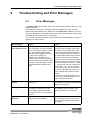
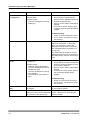
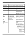
9.1
9.2
Error Messages . . . . . . . . . . . . . . . . . . . . . . . . . . . . . . . . . . . . . . . . 9-1
Troubleshooting while Loading. . . . . . . . . . . . . . . . . . . . . . . . . . 9-15
9.2.1 Troubleshooting while Loading Samples . . . . . . . . . . . . . . . . . . 9-15
9.2.2 Troubleshooting while Loading Reagents . . . . . . . . . . . . . . . . . 9-18
9.3 Worklist Troubleshooting . . . . . . . . . . . . . . . . . . . . . . . . . . . . . . 9-19
9.3.1 Error Detection while creating Worklist . . . . . . . . . . . . . . . . . . . 9-19
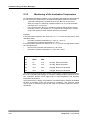
9.3.2 Monitoring of the Incubation Temperature . . . . . . . . . . . . . . . . . 9-20
10
Installation or Removal of the System . . . . . . . . . . . . . . . 10-1
10.1 Installation of the System . . . . . . . . . . . . . . . . . . . . . . . . . . . . . . 10-1
10.2 Removal of the System . . . . . . . . . . . . . . . . . . . . . . . . . . . . . . . . 10-2
11
TOC-4
Technical Data . . . . . . . . . . . . . . . . . . . . . . . . . . . . . . . . . . 11-1
11.1 Power Requirements . . . . . . . . . . . . . . . . . . . . . . . . . . . . . . . . . . 11-1
Elisys Duo - User Manual
11.2
11.3
11.4
11.5
11.6
11.7
12
Laser of the Bar Code Scanner . . . . . . . . . . . . . . . . . . . . . . . . .
Integrated Computer and Connections . . . . . . . . . . . . . . . . . . .
Installation Dimensions and Weight . . . . . . . . . . . . . . . . . . . . .
Environmental Conditions . . . . . . . . . . . . . . . . . . . . . . . . . . . . .
Noise . . . . . . . . . . . . . . . . . . . . . . . . . . . . . . . . . . . . . . . . . . . . . . .
Packaging . . . . . . . . . . . . . . . . . . . . . . . . . . . . . . . . . . . . . . . . . . .
Appendix. . . . . . . . . . . . . . . . . . . . . . . . . . . . . . . . . . . . . . . 12-1
12.1 Accessories and Consumables (Ordering Information) . . . . .
Do´s and Don’ts . . . . . . . . . . . . . . . . . . . . . . . . . . . . . . . . . . . . . .
Do . . . . . . . . . . . . . . . . . . . . . . . . . . . . . . . . . . . . . . . . . . . . . . .
•
Do Not. . . . . . . . . . . . . . . . . . . . . . . . . . . . . . . . . . . . . . . . . . . .
Maintenance . . . . . . . . . . . . . . . . . . . . . . . . . . . . . . . . . . . . . . . . .
Daily and Weekly Checklist. . . . . . . . . . . . . . . . . . . . . . . . . . . . .
Maintenance . . . . . . . . . . . . . . . . . . . . . . . . . . . . . . . . . . . . . . . . .
Monthly Checklist and Specials . . . . . . . . . . . . . . . . . . . . . . . . .
Service Information . . . . . . . . . . . . . . . . . . . . . . . . . . . . . . . . . . .
16
Elisys Duo - User Manual
11-1
11-2
11-2
11-3
11-3
11-3
12-1
13-1
13-1
13-1
14-1
14-1
14-2
14-2
15-1
Index . . . . . . . . . . . . . . . . . . . . . . . . . . . . . . . . . . . . . . . . . . 16-1
TOC-5
TOC-6
Elisys Duo - User Manual
Introduction
Intended Use
1
Introduction
Target of this manual is the explanation of the Elisys Duo system. After having read
the manual, the user should be able to safely operate the Elisys Duo system.
1.1
Intended Use
The Elisys Duo system is classified as other IVD.
The Elisys Duo is designed to automate diagnostic ELISA / EIA and autoimmune
assays that are available from Human. The system is to be used in clinics, laboratories, universities and hospitals containing diagnostic facilities as well as blood
banks. The workplace for the system shall be a dedicated laboratory (area) for diagnostic purposes. The laboratories are not restricted to, but may include small working
spaces (areas). The system is not to be used in a near patient environment.
The Elisys Duo consists of a platform that performs ELISA and similar structured assays, and a PC software that performs several system tasks and provides a graphical
user interface. The Elisys Duo has an interface that can accommodate with an internal PC. The PC has a data connection to an external laboratory information system (which is not included in the Elisys Duo).
The Elisys Duo has a loading bay for samples and reagents, and a loading bay for
disposable tips. The Elisys Duo also has cavities for loading microplates. Loading
of any of these items into the Elisys Duo instrument is to be performed by the operator. Sample and reagent vessels come with attached bar codes that encode the
identifier of the corresponding sample or reagent. The Elisys Duo reads the bar
codes and stores the identifier. Bar codes on microplates can not automatically be
scanned by the system.
Elisys Duo - User Manual
1-1
Introduction
Typographical Conventions
1.2
Typographical Conventions
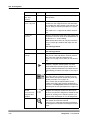
The symbols described hereafter are used in the current manual, on the instrument
and on its packaging. In addition, a specific notation is used to refer to certain particular elements, e.g. buttons, keys.
1.2.1
Warning Messages
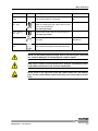
Warning messages are displayed using a safety symbol and printed in special types.
For special situations were used the following security symbols.
Caution, risk of danger to person or damage to equipment! Consult instructions for use!
Biohazard!
Electrical hazard!
Caution, hot surface!
Mechanical hazard!
Automatic start-up!
Laser hazard!
1-2
Elisys Duo - User Manual
Introduction
Typographical Conventions
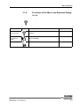
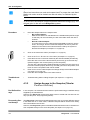
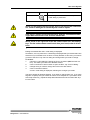
1.2.2
Notes
Notes are indicated with a symbol and printed in special types. The following symbols
are used in particular situations.
Consult instructions for use!
Notes are indicated by this symbol and printed in special types.
Disconnect mains power connector before servicing!
Information about the required access rights for Elisys Duo software functions.
1.2.3
Symbol Keys
Manufactured by
In Vitro Diagnostic
Lot number
Expiration date
Temperature limitations
CE mark
ID number
Serial number
See chapter 1.3.8 on page 1-11
Elisys Duo - User Manual
1-3
Introduction
Typographical Conventions
1.2.4
Special Types
LEDs and Signal Lamps
LEDs (light emitting diode) and signal lamps are printed in special type.
Example: Power LED
Fields
Fields are printed in bold type.
Example: I D field
Menu items and
Buttons
Menu items and buttons are printed in spaced type.
Example: Open button.
Keys
Keys are printed in slanted type.
Example: Press Enter
File examples
File examples are printed in typewriter font.
Example: DRIVER=C:\SERVICE\DRIVERS
1-4
Elisys Duo - User Manual
Introduction
Typographical Conventions
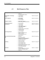
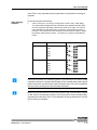
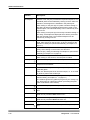
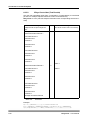
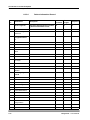
1.2.5
Abbreviations
Abbreviation
Meaning
*.???
Different file extensions (e.g. *.asy, *.txt), see chapter 7.1.6.1 on
page 7-9.
APM
Aspirate Pressure Monitoring system
ASCII
American Standard Code for Information Interchange (ASCII),
pronounced is a character encoding based on the english
alphabet.
ASTM
American Society for Testing and Materials.
ASTM 1381 and ASTM 1394 are determinations for the communication between computers.
COM
COM is the original, yet still common, name of the serial port
interface on PCs. It might not only refer to physical ports, but
also to virtual ports, such as ports created by RS/232 or USB
adapters.
COP
Command Operating Processor
CU
Control Unit
CV
The abbreviation CV stands for “coefficient of variation” and is
the relative standard deviation, which is the quotient of the
absolute standard deviation and the mean of a measured
value.
%CV: The CV multiplied with 100%
EEPROM
An Electrically Erasable Programmable Read-Only Memory, is
a type of non-volatile memory used in computers and other
electronic devices to store small amounts of data that must be
saved when power is removed, e.g., calibration tables or
device configuration.
EIA
Enzyme Immuno Assay
ELISA
Enzyme Linked Immuno Sorbent Assay
Host
In computer networking a host is a main computer (e. g. server,
central computer).
ID
Identification (Number).
LAN
A Local Area Network is a computer network.
LED
Light Emitting Diode
LIMS
A Laboratory Information Management System (LIMS) is computer software that is used in laboratories for the management
of samples, laboratory users, instruments, standards and other
laboratory functions such as invoicing, plate management, and
work flow automation.
LIS
A Laboratory Information System, is a class of software which
handles receiving, processing and storing information generated by medical laboratory processes.
LLD
Liquid Level Detection
Elisys Duo - User Manual
1-5
Introduction
Typographical Conventions
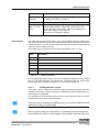
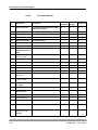
Abbreviation
Meaning
l
A microliter is a unit of volume in the metric system.
(1 l = 0.001 ml = 1*10-6 l)
nm
A manometer is a unit of length in the metric system.
(1 nm = 0.000001 mm = 1*10-9 m = 39.37*10-9 in)
OD
Optical Density
PC
Personal Computer
PS2
The PS/2 (PS2) connector allows the connection of a keyboard
or a mouse to a computer.
QA
Quality control Analysis
RS232
Serial bus standard to connect devices to a computer.
USB
The Universal Serial Bus is a serial bus standard to connect
devices to a computer.
VC
Validation Criteria
VGA
The Video Graphics Array is a standard interface to connect a
screen to a computer.
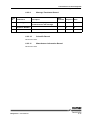
Table 1-1:
Abbreviations
1-6
Elisys Duo - User Manual
Introduction
Safety Instructions
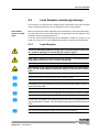
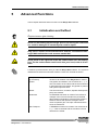
1.3
Safety Instructions
Read all of these instructions! Retain these instructions for reference!
The following safety instructions must be observed at all times, both before
and during operation of the Elisys Duo system!
The operating manual must be kept near the instrument and must be accessible to the user at all times.
The Elisys Duo system is designed and manufactured in accordance with the safety
requirements for electronic and medical systems. If the law issues regulations concerning the installation and/or operation of the instrument, then it is the operator's responsibility to adhere to them.
The manufacturer has done everything possible to guarantee that the equipment
functions safely, both electrically and mechanically. The systems are tested by the
manufacturer and supplied in a condition that allows safe and reliable operation.
1.3.1
General Safety
Follow all warnings and instructions marked on the instrument and in this
manual.
The instrument must only be operated by personnel who have been trained to
use the system.
It is strongly recommended that all first time personnel read this manual prior to working with the instrument
The instrument must only be used in accordance with its intended use.
Use only the consumables and accessories described herein (e. g. tubes, disposable
tips, microplates, etc.).
The manufacturer assumes no liability for any damages, including those to third parties, caused by improper use or handling of the system.
The operator may only perform the maintenance work described in this manual.
Use only the parts recommended in this manual for servicing.
The tests and maintenance work defined by the manufacturer should be performed
to make sure that the operator remains safe and that the instrument continues to
function correctly.
Trained, qualified and authorised service personnel and technicians must perform
any service and maintenance work not described in this manual.
Elisys Duo - User Manual
1-7
Introduction
Safety Instructions
Any changes made to the instrument that are not authorised by the manufacturer will
lead to the loss of guarantee.
The system was developed and tested according to the regulations of the IvD
directive.
Any changes to the instrument that are not authorised by the manufacturer will lead
to the loss of the validity of the conformity to the applicable regulations the manufacturer has declared. In this case, the customer is responsible for the fulfilment of the
applicable regulations.
The instrument may be opened, serviced and repaired by trained, qualified and
authorised service personnel only.
1.3.2
Electrical Safety
For safe electrical operation of the installed instrument the relevant regulatory
provisions have to be observed.
Check that the operating voltage is set correctly on all instrument components
before you connect the system to the mains supply.
This product must be operated from the type of power source indicated on the type
label. If you are not sure of the type of power available, consult an authorized sales
person or your local electric power company.
Use a 3-wire grounding type plug to connect the instrument and all peripherals
to mains supply.
Use only extension cables with a protective conductor and grounded contact.
Grounding of the instrument and its peripheral devices to the same protective earth
potential must be ensured.
Never interrupt the grounding contacts.
There is the risk of an electrical shock if the protective conductor is interrupted within
or outside the device, or has been disconnected.
The instrument must be connected with a delivered connection cable to dedicated socket. The use of a multi plug is not allowed!
Do not allow anything to rest on the power cord.
If you can see that the instrument has become unsafe to use, switch it off and
disconnect it from the mains supply.
If liquid gets inside the instrument, switch it off and disconnect it from the
mains supply. Clean, and dry the respective parts.
Surfaces (floors, work table) must be dry when you are working with the system.
Only use the bottles, tubing and components supplied and recommended for containing liquids on the instrument.
1-8
Elisys Duo - User Manual
Introduction
Safety Instructions
Spare fuses must match the values (nominal voltage, nominal current, and
type) specified by the manufacturer.
Always replace blown fuses, do not try to repair them.
Never short-circuit the fuse holder.
Switch the instrument off and disconnect it from the mains supply before servicing.
Only when directed to do so, should power be supplied. If power is supplied while
any covers are removed, use extreme caution while servicing the system.
Never remove protective guards or secured components as this could expose
live parts.
Electrical connection contacts (plugs, sockets etc.) can be electrically live.
Even after the device has been switched off, components (e. g. capacitors) can carry
a voltage.
All current-carrying parts are sources of danger for an electrical shock.
Ensure the instrument is positioned so that the power supply and main switch
is easily accessible.
The instrument meets the requirements described in standard IEC 61326 on
transient emissions and interference resistance.
This instrument was developed and tested according to CISPR11 Class A. It can
cause radio interference in domestic environment. In this case it may be required to
take action to eliminate such interference.
Before setup and operation of the instrument, the electromagnetic environment
should be evaluated.
Do not use the instrument in the vicinity of sources with excessive electromagnetic
radiation (e.g. unshielded, deliberately operated high frequency sources) since they
could interfere with the proper operation of the instrument.
1.3.3
Laser Safety
Care must be taken when operating and testing the bar code scanners as they
use a laser class 2. Never look directly into the laser beam!
Output causes irritations of the eye if stared into the beam for long periods of time.
See chapter 11.2 on page 11-1 for technical data of the laser (bar code scanner).
For operating and testing the laser, no optical devices may be used.
For operating and testing the laser, watches and mirroring jewellery should be removed.
Use of controls or adjustments or performance of procedures other than those
specified herein may result in hazardous radiation exposure.
Elisys Duo - User Manual
1-9
Introduction
Safety Instructions
1.3.4
Mechanical Safety
Do not place the instrument on an unstable or uneven surface.
The instrument may fall, causing serious damage to the instrument or injure the user.
Never open screw-attached housing parts while the instrument is on.
There is a risk of injury due to moving parts (fan, motor drives).
Only when directed to do so, should power be supplied. If power is supplied while
any covers are removed, use extreme caution while servicing the system.
Do not take off the protective cover during a run and do not reach into the
working area.
Improper handling may cause serious damage to the instrument or injure the user.
If you open the flap or cover, verify that the movement of the pipettor has stopped
before you reach into the working area.
Avoid touching the pipettor and other moving parts while the system is in operation.
Slots and openings are provided for ventilation (are not meant as access
points).
To ensure reliable operation of the instrument and to protect from overheating, these
openings must not be blocked or covered.
Sharp edges! Sheet metal parts and PCBs located behind protective covers
might have sharp edges. Contact might lead to injuries.
Wear cut resistant gloves!
Use caution at corners and edges!
1.3.5
Biological Safety
Risk of infection! Handling of samples and reagents:
Avoid contact between skin/mucous membrane and samples/test reagents or parts
of the instrument which were in contact with samples/test reagents.
The above-mentioned parts are to be treated as being potentially infectious.
Reagents can lead to irritation of the skin and mucous membranes.
Use appropriate gloves, a lab coat, and eye protection (e.g. goggles)!
Observe the instructions in the package inserts for a correct use of the reagents.
If sample material is spilled in the system, clean and disinfect it immediately
by the use of a validated method.
For reagent containers and tubing’s (system liquid and waste), no guarantee
can be provided for any resistance against organic solvents.
For this reason, do not use any organic solvents unless such solvents are expressly
authorised.
1-10
Elisys Duo - User Manual
Introduction
Safety Instructions
Do not autoclave the containers for liquids and waste!
1.3.6
Touch Screen Handling and Cleaning
Operate with a stylus (tip R0.8 or over), or with a finger without applying excessive load.
Sharp edged or hard articles are prohibited.
It is absolutely forbidden to draw lines along with the edge of the housing because
the extreme force will damage the PET/FILM and cause the failure of the touch panel.
Keep the surface clean.
Use soft clothes with neutral detergent or with ethanol may to clean the touch
screen.
Do not use any chemical solvent, acidic or alkali solution.
Do not allow liquid from soaking into the joint of film and glass which may result in
peeling or malfunctioning.
1.3.7
Cleaning the System
Switch the instrument off and disconnect it from the mains supply before
cleaning, disinfection or decontamination.
Liquid detergents, disinfectants or decontamination liquids may not be poured
into the instrument or sprayed inside the system.
For the cleaning, disinfection or decontamination, a cloth moistened with detergent,
disinfectant or decontamination liquid should be used.
Only approved detergents, disinfectants or decontamination liquids may be used.
Only approved cleaning, disinfection or decontamination methods may be used.
For cleaning, disinfection or decontamination, the regulations of the relevant regulatory provisions must be observed.
1.3.8
Disposal
Potential infectious material and all parts that may come in contact with potential infectious material must be disposed according to the applicable local and
national provisions, legislation and laboratory procedures.
All parts that have been replaced, must be disposed according to the applicable local and national provisions and legislation.
The instrument must be disposed according to the applicable local and national provisions and legislation.
The packaging material must be disposed according to the applicable local
and national provisions and legislation.
Elisys Duo - User Manual
1-11
Introduction
Safety Instructions
Single-use containers or tips may not be used repeatedly.
In the European Union, electrical and electonic equipment must not be disposed of with other household-type waste. It must be collected separately.
Please observe the relevant legal regulations effective in your country.
1-12
Elisys Duo - User Manual
Introduction
Positions of Safety Labels and Type Label
1.4
Positions of Safety Labels and Type
Label
If any label gets lost, replace it by an equivalent label!
1.4.1
General Warning Labels
General warning labels are positioned on:
•
on the pipettor arm,
•
on both sides of the loading bay,
•
on both edges of the cover, and
•
next to the dispense pump
1.4.2
Biological Hazard Labels
Biological hazard labels are positioned on:
•
the washer service cover,
•
the disposable tip ramp,
•
the pumps module cover,
•
the waste liquid container, and
•
both washer aspiration bottles.
1.4.3
Electrical Hazard Labels
Electrical hazard labels are positioned on:
•
the main power connector/switch.
1.4.4
Laser Hazard Labels
Laser hazard labels are positioned on:
•
the loading bay bar code scanner.
1.4.5
Type Label
The type label is positioned on the right side of the instrument (near by the mains
switch).
Elisys Duo - User Manual
1-13
Introduction
Positions of Safety Labels and Type Label
1-14
Elisys Duo - User Manual
System Description
2
System Description
The Elisys Duo is a fully automated microtiter plate analyser performing the complete sample processing (sample pre-dilutions, sample and reagent dispensing, incubations, wash processes, plate transports) as well as the photometric
measurement and evaluation. The instrument is controlled via the Windows PC
Elisys Duo software. This software, which was specifically designed for this purpose, allows the user to process the pre-defined assays as well as assays programmed by the user. The clear structure with intuitive user-guidance allows simple
and quick operation of daily routine jobs as well as programming of user-specific assays.
Elisys Duo - User Manual
2-1
System Description
System Overview
2.1
System Overview
2.1.1
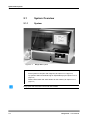
System
Figure 2-1:
Elisys Duo system
1
Cover with touch screen
2
Rack system for samples and reagents (see chapter 2.2.4 on page 2-12)
3
Tip ejection station and waste bag for disposable tips (see chapter 2.2.8.4 on
page 2-16)
4
Wash buffer bottles and waste bottles for the washer (see chapter 2.2.5 on
page 2-14)
Only open and close the cover with the handle!
2-2
Elisys Duo - User Manual
System Description
System Overview
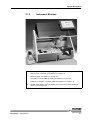
2.1.2
Instrument Modules
Figure 2-2:
Elisys Duo system - instrument modules
5
Pipettor (see chapter 2.2.8 on page 2-15)
6
Service cover of washer (see chapter 2.2.5 on page 2-14)
7
Plate transport (see chapter 2.2.1 on page 2-7)
8
3 positions for disposable tip racks (see chapter 2.2.2 on page 2-9)
9
Positions for dilution or archive plates (see chapter 2.2.3 on page 2-10)
10
Pipettor wash station, tip eject station and cover locking mechanism (see
chapter 2.2.8.4 on page 2-16)
Elisys Duo - User Manual
2-3
System Description
System Overview
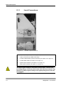
2.1.3
Liquid Connections
Figure 2-3:
Left side - liquid connections
12
Dispense pump (see chapter 2.2.8 on page 2-15)
13
Liquid connections (for details see below)
14
2 washer waste bottles (vacuum extraction) (see chapter 2.2.5 on page 2-14)
15
3 wash buffer bottles (see chapter 2.2.5 on page 2-14)
16
System liquid container (see chapter 2.2.8.2 on page 2-15)
17
Waste liquid container (see chapter 2.2.5 on page 2-14)
The waste liquid container, the washer waste bottles, and the corresponding tubings could have had contact with infectious material. Pay
attention to safety regards! Always wear appropriate gloves, lab coat,
and goggles!
2-4
Elisys Duo - User Manual
System Description
System Overview
The waste liquid container should be placed always under the level of the analyser.
The installation of washer liquid waste bottle and washer foam bottle must be
lined up, that they cannot accidentally fall over during operation!
Figure 2-4:
Liquid connections
System Liquid
System liquid container
Vacuum
Washer liquid waste bottle (trap bottle)
Washer Waste
Washer foam bottle (vacuum bottle)
System Waste
Waste liquid container
Wash buffer 3
Wash buffer bottle - yellow channel
Wash buffer 2
Wash buffer bottle - blue channel
Wash buffer 1
Wash buffer bottle - red channel
Elisys Duo - User Manual
2-5
System Description
System Overview
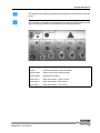
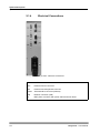
2.1.4
Electrical Connections
Figure 2-5:
Right side - electrical connections
USB
3 USB-connectors
VGA
External monitor connector
PS2
External mouse/keyboard connector
RS232
Serial interface connector (RS 232)
LAN
Network connector (LAN)
18
Main power connector with power switch and main fuses
2-6
Elisys Duo - User Manual
System Description
Use of the Modules
2.2
Use of the Modules
2.2.1
Microplates in the Plate Transport
The plate transport moves microplates between the modules of the Elisys Duo system.
The plate transport can also shake a microplate in order to mix the well contents. The
microplate is moved linearly at a given frequency and amplitude. The shaking time is
controlled through the assay protocol.
You may only insert the microplates into the plate transport if you are requested to do so by the Elisys Duo software!
Use only exact modelling of microplates to ensure correct tracking.
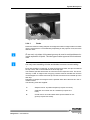
Figure 2-6:
Elisys Duo - User Manual
Microplate in the plate transport
2-7
System Description
Use of the Modules
Load the microplate into the plate frame of the plate transport (7) after the request of
the Elisys Duo software. Position A1 should be at the rear right. Push the microplate
firmly down so that they lay on the floor completely and evenly.
2-8
Elisys Duo - User Manual
System Description
Use of the Modules
2.2.2
Figure 2-7:
Disposable Tip Racks
Disposable tip racks
Please carefully check the tip racks allocation, following the specific color
code and type in the software. A tip misplaced can not be recognized by the
instrument and may cause mechanical damage!
Insert the disposable tip racks into the corresponding rack position (8) after the request of the Elisys Duo software. The rack marker should be at the rear right (see
triangular markers). Push the disposable tip rack(s) firmly down so that they lay on
the floor completely and evenly.
Elisys Duo - User Manual
2-9
System Description
Use of the Modules
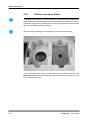
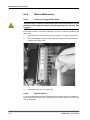
2.2.3
Dilution or Archive Plates
To be able to use dilution or archive plates, it is required to use a metal base
plate. The metal base plate allows the correct detection of liquid surface as
well as the usage of the complete liquid volume in the dilution or archive plate
(less the specified remaining volume).
Use only exact modelling of microplates to ensure correct tracking.
Figure 2-8:
Metal base plate in the right position
Lay the metal base plate on the corresponding position (9) after the request of the
Elisys Duo software. Push the metal base plate firmly down so that they lay on the
floor completely and evenly.
2-10
Elisys Duo - User Manual
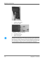
System Description
Use of the Modules
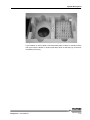
Figure 2-9:
Dilution or archive plate in the right position
Lay the dilution or archive plate on the metal base plate. Position A1 should be at the
rear right. Push the dilution or archive plate firmly down so that they lay on the floor
completely and evenly.
Elisys Duo - User Manual
2-11
System Description
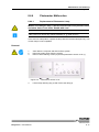
Use of the Modules
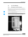
2.2.4
Rack System for Samples and Reagents
The rack system is used for loading samples and reagents located in reagent tubes
or bottles into the Elisys Duo system by means of so-called racks. By means of the
pipettor, the samples and the reagents can then be distributed in the course of a test
run.
To avoid the confusion of samples or reagents, the rack system is provided with a
bar code scanner (on the right hand side). By means of this scanner, the bar codes,
which are applied on the corresponding reagent tubes or bottles can be read and
processed in the Elisys Duo software later.
CAUTION: Laser radiation - do not stare into beam!
The rack system is provided with 12 tracks for insertion of up to 12 racks, depending
on their width. The track to be used is marked by lamp (LED).
Never move your hand into the rack system, if the Elisys Duo system is
operating. The pipettor could cause injury during the loading of samples or reagents with its tip.
Do always push in the racks into the rack system with the handle or pull it out
again with the handle.
Insert the racks carefully to avoid tipping over and spilling of bottles or tubes.
In one rack, only tubes of the same type may be used to avoid problems during the aspiration of liquids. The tube type must be approved for the relevant
rack.
Never load more than one rack at the same time! For proper bar code identification the racks must be loaded one after the other, as indicated by the
LEDs.
2-12
Elisys Duo - User Manual
System Description
Use of the Modules
Figure 2-10: Rack system with racks
2.2.4.1
Racks
Racks are used for loading samples and reagents located in reagent tubes or bottles
into the rack system in a controlled way. Depending on the purpose of use, there are
different racks.
In one rack, only tubes of the same type may be used to avoid problems during the aspiration of liquids. The tube type must be approved for the relevant
rack.
Use only exact modelling of tubes and bottles to ensure correct tracking.
Each rack includes a contact pin; on racks occupying one track, this pin is located at
the top centre, and on the broader racks at the top right.
The software specifies which track is to be used for the respective rack. This is indicated by a LED. A reagent rack occupying 3 tracks must be inserted such that the
contact tappet is in contact with the lit up LED. Each rack has to be inserted up to the
limit stop.
Reloading of sample and reagent racks is possible when the instrument is in the incubation mode.
The following racks are supplied:
T:
Sample rack for 16 patient samples (occupies one track).
4:
Calibrator and control rack for 15 bottles (occupies one
track).
5:
Combi rack for 6 round bottles and 2 square bottles for reagents (occupies two tracks).
Elisys Duo - User Manual
2-13
System Description
Use of the Modules
2.2.5
Washer and Wash Buffers
To be able to wash microplates in the course of a test, the Elisys Duo system is provided with a washer. By means of the washer, the microplates can be cleaned stripwise with different wash buffers.
The wash head of the washer aspirates liquid from the microplate wells as well as
dispenses wash buffer into them. The wash head comprises eight-dispense nozzles
and eight slightly longer aspiration nozzles. The wash head is lowered into the microplate wells for each aspiration or dispensing step.
The washer is located behind a cover (6).
A maximum of 3 bottles (1 x 1 litre, 2 x 2 litres - 15) can be used for various wash
buffers to clean the microplates and cleaning fluid (e.g. distilled water) to clean the
washer head.
The connection fitting (13) consists of 3 colour-coded connection pairs: one tubing
and one level sensor each per bottle.
Two waste bottles (14) are available for the wash unit. One waste bottle contains the
liquid waste which is pumped to the waste container which is positioned below the
instrument. The second bottle serves as overflow protection.
2.2.6
Incubator and Stacker
Next to the washer there are two independent heatable incubator chambers; the microplates are automatically transported into these incubators and out again according to the assay protocol.
The heatable incubator chambers can also shake a microplate in order to mix the
well contents. The microplate is moved linearly at a given frequency and amplitude.
The shaking time is controlled through the assay protocol.
The instrument is also equipped with three light-protected storage chambers (stacker) accommodating microplates for room temperature incubation. It is located below
the incubator.
2.2.7
Photometer
The photometer uses photodiodes located above the microplate to measure the
amount of light passing through the microplate wells from the light source below the
microplate. The optical system includes optical interference filters (up to 8 filters),
mounted in a filter wheel, to obtain monochromatic light of the desired wavelength
and optical lenses to obtain an optimal light beam passing through the microplate
wells.
The photometer measures the absorbance in eight wells simultaneously as the microplate moves through the photometer. Comparing the measurement values to the
zero value with air in between (equivalent to 100 % light source output), the absorbance is calculated using the Lambert-Beer law. A reference channel continuously
compensates for any instability of the light source.
The photometer (400 - 700 nm) is installed in the lower left part of the instrument.
2-14
Elisys Duo - User Manual
System Description
Use of the Modules
2.2.8
Pipettor and Dispense Pump
The Elisys Duo system is provided with a fully automatic pipetting system.
The microprocessor-controlled dispense pump (12) installed on the left side of the
system allows a very precise aspiration and dispensing of the liquids to be pipetted.
The tube system of the pipetting system is filled with system liquid.
The pipettor uses disposable tips to avoid cross-contamination. Different sizes of disposable tips (300 l or 1100 l) can be attached to the tip adapter of the pipettor automatically. After pipetting the disposable tips can be emptied in the wash station (10)
or dropped into the tip eject station (10).
A plastic cover protects the visible working area. The closed position of
this flap is monitored by a contact switch. The Elisys Duo cannot be operated without this cover, in order to protect the operator from getting
in contact with the working area during a run. If these safety precautions are not observed strictly, the operator may get hurt or contract an
infection, or the instrument may get damaged.
In case no cover lock is installed, the software can be configured so that the
system is stopped immediately when the instrument cover is opened during
a run.
2.2.8.1
Dispense Pump
The dispense pump is used for transferring liquids (samples, controls, standards, reagents or diluents).
The disposable tip is moved into the source position (e.g. sample, reagent) by the
pipettor to aspirate liquid. The downward motion of the pump’s syringe plunger causes the system liquid to aspirate fluid into the disposable tip.
After the liquid is aspirated, the tip is moved to the destination position (e.g. microplate, dilution plate). The upward motion of the syringe plunger causes the system
liquid to dispense fluid through the disposable tip into the destination position.
The motion of the syringe plunger coupled with the system liquid causes system fluid
to move throughout the tubing and the aspiration and dispensing of liquid and airgaps
in the disposable tip.
2.2.8.2
System Liquid Container
The system liquid container (16) is located beside, behind or under the instrument
and connected through tubing. The system liquid container is fitted with an electric
level sensor.
The system liquid can be filled as soon as the instrument is properly installed.
To fill system liquid:
1.
Prepare the system liquid (deionised water).
2.
Open the container screw cap and pour in the system liquid.
3.
Close the screw cap and make sure the level sensor and connections are
correctly set.
Elisys Duo - User Manual
2-15
System Description
Use of the Modules
The level sensor is used by the system to check the available quantity of system liquid. This check is performed each time a selftest is conducted (see chapter 5.1 on page 51). The system will also warn the operator if the level of system liquid becomes insufficient during a run.
A visual check of the system liquid container is recommended every morning before
starting the system (see chapter 8.2 on page 8-3).
2.2.8.3
Liquid Level Detection (LLD)
Each disposable tip possesses independent liquid level detection (LLD) capabilities.
LLD detects liquid by detecting a change in capacitance. As a tip enters the sample
or reagent well (source or destination) the LLD circuitry baselines. The tip continues
to track down until a change of capacitance is detected. Once liquid is detected, the
tips submerge in the liquid to a programmed submerge depth. As the system aspirates/dispenses liquid the tip tracks down/up while liquid level decreases/increases.
Tracking is done by calculating the change of liquid level using the well geometry.
This mechanism ensures that sample or reagent will be aspirated/dispensed without
unnecessary external contamination of the tip.
Disposable tips with LLD capability are impregnated with carbon and are black in
color. These are denoted as “conductive” tips. Tips not impregnated with carbon, normally clear in color, have no LLD capability and can only be used if a fixed height for
aspirating or dispensing is used.
2.2.8.4
Tip Ejection Station and Pipettor Wash Station
Tip ejection station and waste bag (10):
The opening serves as ejection station for disposable tips. The ejected tip is transported into the waste bag via a slide which is attached to the front side of the instrument. The waste bag can be taken out of the holding device and replaced. After
removal of the waste bag, the ejection station can be pulled off by hand.
The ejection station and the waste bag could have had contact with infectious material. Pay attention to safety regards! Always wear appropriate gloves, lab coat, and goggles!
Pipettor wash station (10):
The pipettor wash station is located behind the tip ejection station.
2-16
Elisys Duo - User Manual
System Description
Use of the Modules
2.2.9
Touch Screen
With the integrated touch screen it is very easy to use the system. You made all inputs with a stylus (tip R0.8 or over) or a finger directly on the touch screen. An external keyboard or mouse are not needed.
Use:
•
Keyboard (alphanumeric inputs, e.g. A - Z, 0 - 9, etc.):
The Elisys Duo software provides special input dialogs to enter letters (see
chapter 3.6.1 on page 3-21) or numbers (see chapter 3.6.2 on page 3-23). Additional
there is a callable screen keyboard to enter letters or numbers on the windows systems (see Windows Start button).
•
Mouse:
Mouse pointer: Touch the screen with your finger. Now the mouse pointer will
follow your moving finger.
•
Single mouse click: Touch the screen with your finger once.
•
Double mouse click (double click): Touch the screen with your finger twice.
Do not wait between the first and the second touch.
Note the handling and cleaning hints for touch screens in the safety instructions (see chapter 1.3.6 on page 1-11).
Elisys Duo - User Manual
2-17
System Description
Accessories and Consumables
2.3
Accessories and Consumables
The necessary accessories and the following consumables can be purchased from
Human:
•
Sample and reagent racks (with bar codes).
•
Bar code labels for reagent and sample racks.
•
Tip racks with 300 l / 1100 l disposable tips.
•
Waste and system liquid containers with or without level sensors and tubing
connections.
•
Wash buffer and clean fluid bottles.
•
Trap flask and vacuum flask.
•
Spare reagent bottles.
•
Bar code labels for reagent bottles.
•
Various tubings.
•
Filters for the photometer.
•
Halogen lamp for the photometer.
•
Sample rack storage tray.
2-18
Elisys Duo - User Manual
System Description
Principles of Methods
2.4
Principles of Methods
2.4.1
Absorbance Photometry
The measurement principle of absorbance photometry plays the most important role
in clinical chemistry. With this method, the intensity of a monochromatic light beam
of a suitable wavelength is compared before and after passing through a sample.
The degree of attenuation of intensity of the light beam provides a measure of the
concentration of the substance under investigation. The photometer consists of a
polychromatic or monochromatic light source. In the case of the Elisys Duo, this is
a halogen lamp which emits a spectrum. The desired wavelength is filtered out using
a wavelength selector (i. e. a filter). The light with this wavelength passes through the
sample with the substance to be measured in an optically clear solution. A part of the
light is absorbed in the sample. The intensity of the light coming out of the sample is
measured with a measuring cell (detector). The light striking the detector is converted
into an electrical signal and stored as the measurement signal.
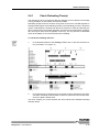
2.4.2
Bichromatic Measurement
In the case of the bichromatic measurement principle, measurements are performed
at two wavelengths, the measuring and the reference wavelength. The measuring
wavelength is close to the absorbance maximum of the chromogen. The absorbance
is mainly dependent on the amount of chromogenic substance in the sample. The
reference wavelength lies outside the absorbance range of the chromogen and indicates the blank value of the sample. The absorbance value of the reference wavelength is substracted from the absorbance value of the measuring wavelength. In this
manner, external influences such as scratches on the microtiter plate, dust, turbidity
of the solution and the drift of the electronic measuring instrument can be compensated.
Elisys Duo - User Manual
2-19
System Description
Principles of Methods
2-20
Elisys Duo - User Manual
Basic Functions
Menus and Symbols
3
Basic Functions
This chapter describes the basic functions of the Elisys Duo software. Additionally,
a short overview over all software menus and symbols is included in this chapter.
Required access rights: Start Worklists
3.1
Menus and Symbols
The following alphabetic sorted tables describe all various menu items. Several menu items are enabled only when you can use them.
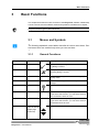
3.1.1
General Functions
Category
Function
Symbol
Description
Edit
OK
The input/change is applied and the corresponding dialog is closed.
Edit
Cancel
The input/change is not applied and the corresponding dialog is closed.
Edit
Redo
With this function, you can redo the changes previously made.
Edit
Undo
With this function, you can undo the previous
changes.
Help
Help
Shows the on-line help.
Keyboard
Ctrl
Simulates the Ctrl key on your keyboard.
If you select this function, you can select several
non-consecutive items in a list.
Keyboard
Shift
Simulates the Shift key on your keyboard.
If you select this function, you can select several
consecutive items in a list.
Search
Scroll buttons
(active in case of
multiple page
documents)
Elisys Duo - User Manual
Jump to the previous/next line.
3-1
Basic Functions
Menus and Symbols
Category
Function
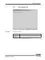
Symbol
Description
Search
Scroll buttons
(active in case of
multiple page
documents)
Jump to the previous/next page.
Search
Scroll buttons
(active in case of
multiple page
documents)
Jump to the first/last page.
Selection
Se le ct All
This function selects all shown items in a list.
Selection
This symbol indicates that the corresponding
function is not selected. (dark green)
Selection
This symbol indicates that the corresponding
function is selected. (light green)
Table 3-1:
General
3-2
Elisys Duo - User Manual
Basic Functions
Menus and Symbols
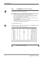
3.1.2
Functions of the Menu and Selection Dialog
File
Shows a selection dialog (see chapter 3.6.3 on page 3-24) for the following
functions. These are the same functions as in the menu F i l e .
Function
Symbol
Description
Chapter
Clo s e
Closes the active document.
-
Ex it
Terminates the program.
-
Ne w
Shows a selection dialog to create new document
(e. g. assays, worklists or reports).
chapter 3.2.1 on page 310
Ne w Wo rklist
Opens the S e t - U p P a n e l dialog to create a
new worklist.
chapter 4.4 on page 4-10
+ chapter 5.3 on page 513
Open
Shows a selection dialog to open a document.
chapter 3.3.1 on page 311
Pr int
Prints the active document (e. g. worklist, report). chapter 3.5.1 on page 316
Pr int Pr eview
Shows the active document as print preview.
chapter 3.5.3 on page 320
Pr int Se tu p
Defines the printer and printing options.
chapter 3.5.2 on page 318
Sa v e
Saves the active document (e. g. worklist, report). chapter 3.4 on page 3-14
Sa v e a s
Saves active document (e. g. worklist, report)
under a new name.
chapter 3.4 on page 3-14
Re c e n t P r o tocols
Shows the last opened and already saved assay
protocol files for selection.
-
Re c en t
Re s ults
Shows the last opened and already saved result
files for selection.
chapter 4.9.3 on page 465
Re c en t
W or kl i st s
Shows the last opened and already saved worklists for selection.
-
Elisys Duo - User Manual
3-3
Basic Functions
Menus and Symbols
Table 3-2:
Menu and selection dialog F i l e
3-4
Elisys Duo - User Manual
Basic Functions
Menus and Symbols
3.1.3
Functions of the Menu Edit
The functions of the menu Ed it can only be used if a worklist is active.
Function
Symbol
Description
Chapter
Ex p ort
Ar ch ive
Exports archiving information as file.
-
Load Additional Tips
Allows the reloading of disposable tips.
chapter 4.7.6.1 on
page 4-43
Lot Specific Values
Opens the L o t S p e c i f i c V a l u e s dialog to
show or edit the required reagents information.
chapter 4.5 on page 4-11
Optimise
Optimises the schedule of the defined worklist.
chapter 5.5.1 on page 532
Pa n e l De f i nition
Opens the S e t - u p P a n e l dialog to edit the
current worklist.
chapter 4.4 on page 4-10
Not used.
This function is also called E d i t Pa n e l
Pa n e l
Options
Opens the W o r k l i s t O p t i o n s dialog to
change worklist processing options.
chapter 5.4 on page 5-24
This function is also called E d i t O p t i o n s
St art
Opens the L o a d dialog to allocate the required
resources. After that, a run using the current
worklist will be started.
chapter 4.7 on page 4-28
St op
Pauses the current run. The run can be continued
again and one or several plates can be removed
from processing. Or the entire run can be aborted
completely.
chapter 4.8.5 on page 455
Un lo ad F i n i s h e d P la t e s
Allows the unloading of fully processed plates
before the end of the run
chapter 4.10.1.2 on
page 4-67
Table 3-3:
Elisys Duo - User Manual
Menu E d i t
3-5
Basic Functions
Menus and Symbols
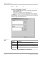
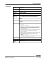
3.1.4
Function
Symbol
Functions of the Menu and Selection Dialog
Utilities
Description
Chapter
Export
Results
Each time a (*.res) result report is calculated and
displayed on the screen, you can decide to export
it.
chapter 6.1.4.1 on
page 6-11
Log-Off/
Log-On
Allows to change the user.
-
Maintenance
Allows to select and execute programmed maintenance jobs.
chapter 8.5 on page 8-10
Options
Definition of software parameters (e. g. user
access rights, laboratory details, preferences,
directories, file polling, ASTM).
chapter 7.1 on page 7-1
Patient
Details
Opens the complete P a t i e n t Ed i t o r dialog to
view or edit patient data.
chapter 5.2 on page 5-4
Present
Carriers
Manual plate control.
chapter 5.5.3 on page 538
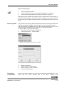
Scanner
Allows to choose the track where the system will
accept the next rack. Click on the desired track in
the S e l e c t a T r a c k dialog.
If the system has been started by one user and
another user wants to take over, the second user
should log-in under his/her own user name. To do
so, it is not necessary to shut down the system
and restart it.
Not recommended for normal use.
-
Note: Double lane racks can only be inserted in
every 2nd track (the software will reject rack otherwise.
See warnings below.
chapter 5.9 on page 5-53
Select Language
Allows to change the software language.
Selftest
Performance of a self test (initialization).
chapter 5.1 on page 5-1
System
Setup
Definition of instrument parameters.
chapter 7.2 on page 7-11
Only visible when no window is opened.
3-6
Elisys Duo - User Manual
Basic Functions
Menus and Symbols
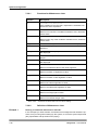
Function
Symbol
Description
Chapter
System Utilities
Manual plate control.
Not recommended for normal use.
chapter 5.5.3 on page 538
Turn Scanner Off
Switches the loading bay bar code scanner off.
-
Note: The loading bay bar code scanner moves
back to its park position.
See warnings below.
Turn Scanner On
Switches the loading bay bar code scanner on.
-
Verify
Checks the photometer using the reader verification plate.
See ’Reader Verification
Plate Manual’
Volume Offset
Definition of pipetting volume correction.
-
See warnings below.
Only used for development and manufacturing.
Table 3-4:
Menu U t i l i t i e s
Never use the loading bay as storage space! The moving bar code scanner could be damaged or stored objects could be upset.
Only load or unload on the indicated lane. Wait for a load/unload message! Wait until the bar code scanner stands idle!
Never reach on the right side of the bar code scanner into the loading
bay! The bar code scanner could crash into your hand, when it drives
back.
Elisys Duo - User Manual
3-7
Basic Functions
Menus and Symbols
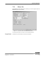
3.1.5
Function
Symbol
Functions of the Menu and Selection Dialog
Windows
Description
Chapter
Arrange
I co ns
Stacks all minimized windows and aligns them
from the lower left to the upper right of the workspace.
-
Cascade
Stacks all windows and aligns them from the
upper left to the lower right of the workspace.
-
New Window
Shows the active document in a new window.
The new window is only a new view of the document and not a new document.
-
More Entries
Shows the name of all opened documents/windows. Select one entry to move the document on
the top.
-
Tile
Stacks all windows and aligns them in rows.
-
Table 3-5:
Menu and selection dialog W i n d o ws
3-8
Elisys Duo - User Manual
Basic Functions
Menus and Symbols
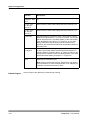
3.1.6
Function
Symbol
Functions of the Menu and Selection Dialog
Help
Description
Chapter
Ab o u t
Elisys Duo
Shows the version number of the Elisys Duo
software.
-
Co n t e x t
Se n s i t i v e
He lp
Shows the on-line help of the selected function
(when available).
-
He lp T op i cs
Shows the on-line help (when available).
-
Table 3-6:
Elisys Duo - User Manual
Menu and selection dialog He lp
3-9
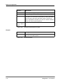
Basic Functions
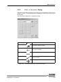
New
Function
3.2
New
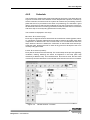
3.2.1
Functions of the Selection Dialog New
Symbol
Description
Chapter
Assay
Opens the S el e c t A s s ay P r o t o c o l
T y p e dialog to create a new assay.
see "Assay Programming Manual"
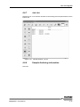
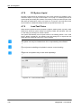
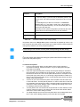
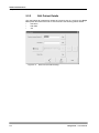
Job List
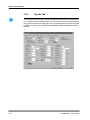
Shows a list of patient IDs with the assays to be
performed for each patient, i.e. patient data and
test orders already stored in the system and not
yet processed. This corresponds to the data currently available in the P a t i e n t E d i t o r dialog.
This function is useful because it allows you to
know rapidly if there is any "back log" or if there is
a lot of work remaining to be done. This J o b
L i s t can be printed.
-
This J o b L i s t is different from the J o b L i s t
displayed in the W o r k l i s t window. The J ob
L i s t displayed in the W o r k l i s t window shows
the patient IDs and assays included in that worklist
Patient
Results
Report
Opens the P a t i e n t R e s u l t s dialog to create
a patient result report.
(see chapter 5.7 on
page 5-48)
QA Analysis Report
Opens the Q . A . A n a l y s i s dialog to create a
QA analysis report.
chapter 5.8 on page 5-52
Spectral
Response
If you select S p e c t r a l R e s p o n s e , the system asks you to load a test plate. The photometer
then perform readings of the 96 wells on the plate
using all the installed filters. From these readings,
the system produces a spectral response curve.
Suggested test and reference filters are displayed
on the screen. Double-click on a specific well to
display the curve recorded for this well. A further
double-click shows the overview again.
-
Worklist
Opens the S e t - U p P a n e l dialog to create
and start a new worklist.
chapter 4.4 on page 4-10
Table 3-7:
Selection dialog N e w
3-10
Elisys Duo - User Manual
Basic Functions
Load (Open)
3.3
Load (Open)
With the function O p e n , results, worklists, event logs etc. stored/saved on the PC
can be reloaded and displayed. In a first step, the type of file is selected, in the second step, the file itself is selected.
3.3.1
Function
Symbol
Functions of the Selection Dialog Open
Description
Chapter
ASCII
Pa t i e n t
Information
Shows the O p e n dialog to open ASCII patient
information files.
chapter 6.1.3 on page 65
As sa y Protocol Files
Shows the O p e n dialog to open assay protocol
files.
see "Assay Programming Manual"
Ev e n t L o g
Files
Shows the O p e n dialog to open event log files.
chapter 4.6.6 on page 423
Re a g e n t
Layout Files
Shows the O p e n dialog to open reagent layout
files.
-
Result Files
Shows the O p e n dialog to open result files.
chapter 4.9.3 on page 465
Selftest
Re p o r t s
Shows the O p e n dialog to open selftest report
files.
chapter 5.1 on page 5-1
Sp e c t r u m
Files
Shows the O p e n dialog to open spectrum files.
-
Verification
Re p o r t s
Shows the O p e n dialog to open verification
report files.
-
W or kl i st
Files
Shows the O p e n dialog to open worklist files.
chapter 5.3.4 on page 523
Table 3-8:
3.3.2
Selection dialog O p e n
Open a File
With the function O p e n , results, worklists, etc. stored on the PC can be reloaded
and displayed. For this purpose, the Open dialog is selected. In this dialog, the
storage position (folder) and the file can be selected.
Elisys Duo - User Manual
3-11
Basic Functions
Load (Open)
Figure 3-1:
Open dialog
3-12
Elisys Duo - User Manual
Basic Functions
Load (Open)
Function
Symbol
Description
File name
-
F iles of ty pe
Shows the file type (see chapter 7.1.6.1 on page 7-9)
Filter
With this function, the number of files displayed
can be limited.
After pushing the button, the E d i t T e x t dialog
(see chapter 3.6.1 on page 3-21) is opened. After the
entry, only those files containing the entered text
are displayed. The filter ignores capitalisation.
Example:
Filter input: 0706
Displayed files: Plate07062001, Plate07062701
Folder up
With this button, you can move to the superordinate folder.
Example:
C:\Programme\Human\System
=> C:\Programme\Human
Look in
Shows the selected or defined folder (see
chapter 7.1.6 on page 7-8) to open the file.
Recent
Files
After clicking on this function, only files are displayed which have already been opened recently.
If this function is clicked on again, all files are displayed again.
This function has priority over the F i l t e r function.
Table 3-9:
Elisys Duo - User Manual
Functions of the O p e n dialog
3-13
Basic Functions
Save
3.4
Save
Save
With the function S a v e , results, worklists, etc. can be saved on the PC. If no file has
been assigned up to now, the function S a v e a s is opened automatically.
Save as
With the function S a v e a s , results, worklists, etc. can be saved on the PC. For this
purpose, the S a v e a s dialog is opened. Here, the storage location (folder) and the
file name can be defined. If a file with the entered file name already exists, Elisys
Duo software requires whether to overwrite the existing file.
Figure 3-2:
S a v e a s dialog
3-14
Elisys Duo - User Manual
Basic Functions
Save
Function
Symbol
Description
Edit
After clicking on the E d i t button, the E d i t
T ex t dialog (see chapter 3.6.1 on page 3-21) is displayed. Here, a new file name can be entered.
File name
Shows the existing, or automatically generated
file name
Folder up
With this button, you can move to the superordinate folder.
Example:
C:\Programme\Human\System
=> C:\Programme\Human
New folder
By means of this button, a new folder can be created. The name is entered in the E d i t T e x t
dialog (see chapter 3.6.1 on page 3-21).
Save
After clicking on the S a v e button, the file is
saved with the entered file name.
Save as
type
Shows the file type (see chapter 7.1.6.1 on page 7-9)
Save in
Shows the selected or defined folder (see
chapter 7.1.6 on page 7-8) to save the file.
Table 3-10:
Elisys Duo - User Manual
Functions of the S a v e a s dialog
3-15
Basic Functions
Print on the Printer
3.5
Print on the Printer
With the function Pr int , results, worklists, etc. can be printed with the printer. Before
printing, there is the possibility to select the printer, to adapt the printer settings and
to view the printout as preview on the screen.
3.5.1
Print
With the function P r i n t , results, worklists, etc. can be printed directly.
Figure 3-3:
P r i n t dialog
Print er Area
Function
Description
Name
Displays the standard printer. With the list,
another printer can be selected.
Print to file
After the selection of this function, a file is created
instead of a printout. The file is a pure print file
and cannot be opened with the Elisys Duo software.
Properties
Shows the properties dialog of the selected
printer. See printer manual for detailed information an setings.
S t a t u s /T y p e/W h e r e
Information about the printer.
Table 3-11:
Functions of the P r i n t dialog - P r i n t e r area
3-16
Elisys Duo - User Manual
Basic Functions
Print on the Printer
Print range
Area
Function
Description
All
Prints the complete document (results, assay
etc.).
Pages
Prints the specified pages of the document.
Selection
Prints the marked part of the document.
Table 3-12:
Functions of the P r i n t dialog - P r i n t r a n g e area
Copies Area
Function
Description
Collate
If more than one copy is to be printed, you can
specify here whether the printouts are to be collated.
Number of copies
By means of this function, the number of copies
can be set.
Table 3-13:
Elisys Duo - User Manual
Functions of the P r i n t dialog - C o p i e s area
3-17
Basic Functions
Print on the Printer
3.5.2
Print Setup
With the function P r i n t S e t u p, the printer to be used can be selected and preconfigured. The settings are applicable for all subsequent printouts.
Figure 3-4:
P r i n t S e t u p dialog
Print er Area
Function
Description
Name
The standard printer is displayed. With the list,
another printer can be selected.
Print to file
After the selection of this function, a file is created
instead of a printout. The file is a pure print file
and cannot be opened with the Elisys Duo software.
Properties
Shows the properties dialog of the selected
printer. See printer manual for detailed information an setings.
S t a t u s /T y p e/W h e r e
Information about the printer.
Table 3-14:
Functions of the P r i n t dialog - P r i n t e r area
Paper Area
Function
Description
Size
Allows the selection of the size if the paper to be
used.
Source
Allows the selection of the paper tray where the
selected paper lays in.
Table 3-15:
Functions of the P r i n t S e t u p dialog - P a p e r area
3-18
Elisys Duo - User Manual
Basic Functions
Print on the Printer
Orient ation
Area
Function
Description
Landscape
The selected paper is used crosswise.
Portrait
The selected paper is used on edge.
Table 3-16:
Elisys Duo - User Manual
Functions of the P r i n t S e t u p dialog - O r i e n t a t i o n area
3-19
Basic Functions
Print on the Printer
3.5.3
Print Preview
This function allows a preview of the printout on the screen. In this way, for example
printer presettings can be checked.
Function
Description
Close
Close the print preview.
Next Page
Shows the next page.
Prev Page
Shows the previous page.
Print
Allows the printout of the preview (see chapter 3.5.1
on page 3-16).
T wo P a ge
Shows two pages on the screen.
Zoom In
Scale up the shown page.
Z oo m O u t
Scale down the shown page.
Table 3-17:
Functions of the P r i n t P r e v i e w dialog
3-20
Elisys Duo - User Manual
Basic Functions
Edit and Selection Dialogs
3.6
Edit and Selection Dialogs
3.6.1
Edit Text Dialog
The E d i t T e x t dialog allows the convenient entry of text on a touch screen monitor. For that, a "keyboard" is displayed on the screen for the entry of the text.
The entry itself is displayed in a separate text area. Next to this text area, the relevant
purpose is displayed (e.g. password).
Figure 3-5:
Elisys Duo - User Manual
E d i t T e x t dialog (example: password dialog)
3-21
Basic Functions
Edit and Selection Dialogs
Function
Symbol
Description
Cancel
The entry is not imported and the E d i t T e x t
dialog is closed.
Delete
Pushing the De le te button deletes the character or digit on the left side of the cursor.
Left
Pushing the left button makes the cursor jumping
to the left by one figure.
OK
The entry is applied and the Ed it T e xt dialog
is closed.
Right
Pushing the right button makes the cursor jumping to the right by one figure.
Shift
Sh i f t switches to upper case for the next typed
character only.
Shift Lock
S h i f t L o c k switches between upper and lower
case, respectively between numbers or special
characters.
•
•
Table 3-18:
Not activated: Numbers or special characters
can be used, which are displayed in the lower
part of the corresponding button, as well as
lower case characters.
Activated: Special characters can be used
which are displayed in the upper part of the
corresponding button and all characters in
upper case.
Functions of the E d i t T e x t dialog
3-22
Elisys Duo - User Manual
Basic Functions
Edit and Selection Dialogs
3.6.2
Edit a Number Dialog
The Ed it a Nu mb er allows the convenient entry of numbers on a touch screen
monitor. For that, a "numerical keyboard" is displayed on the screen for the entry of
the numbers.
The entry itself is displayed in a separate text field.
Figure 3-6:
Function
Enter a Number dialog
Symbol
Description
Canc el
The entry is not applied and the E d i t a
N u m b e r dialog is closed.
Delete
By pushing the button, the digit on the left side of
the cursor is deleted.
Minus
The displayed value is decreased by one.
OK
The entry is applied and the E d i t a N u m b e r
dialog is closed.
Plus
The displayed value is increased by one.
Table 3-19:
Elisys Duo - User Manual
Functions of the E d i t a N u m b e r dialog
3-23
Basic Functions
Edit and Selection Dialogs
3.6.3
Selection Dialog
Selection dialogs allow you to select a special function. The use of the selection dialogs is very easy. Search your desired function. If necessary, use the arrow buttons
(see chapter 3.1.1 on page 3-1). Click on the desired function.
Figure 3-7:
M a k e a S e l e c t i o n d i a l o g (e.g. O p e n )
3-24
Elisys Duo - User Manual
Use of the System
4
Use of the System
In this chapter, the process of a test case from switching on till switching off the system for a "normal" user is described with the right to start a worklist.
Required access rights: Start Worklists
The basic functions of the Elisys Duo software are described in chapter 3 on page 3-1.
Additional functions for "normal" users and for users with additional rights are described in chapter 5 on page 5-1.
Do not use an external keyboard for normal use of the Elisys Duo system.
Elisys Duo - User Manual
4-1
Use of the System
Brief Sequence Plan
4.1
Brief Sequence Plan
Start-up
•
•
•
Maintenance
Switch on
Start Elisys Duo software
chapter 4.2 on page 4-3
Load Samples and Assign
Assays
•
•
Load samples
Assign assays
chapter 4.3 on page 4-5
Create a Worklist
•
•
•
Check plates
Check assays
Check samples
chapter 4.4 on page 4-10
Lot Specific Values
•
•
Enter batch numbers
Enter assay protocol parameters
chapter 4.5 on page 4-11
The Worklist Window
•
Check worklist
chapter 4.6 on page 4-14
Start Worklist
•
•
•
•
•
•
•
•
Load samples
Load reagents
Load unstable reagents
Load dilution plates
Load tip racks
Fill wash buffer and clean fluid
Fill system liquid
Load test plates
chapter 4.7 on page 4-28
Processing the Run
•
•
•
•
•
Pre-run checks
Steps of a typical test run
What you can do
System/Pipetting errors
System pause
chapter 4.8 on page 4-49
End of Run/Result Report Window
•
•
•
•
•
•
Structure
Result interpretation
Editing/Recalculating the results
Save/Open the result report
Print the result report
Export the results
chapter 4.9 on page 4-58
Unloading
•
•
•
•
•
•
Unload test plates
Unload sample racks
Unload reagent racks
Unload tip racks and dilution plates
Unload other resources
Unload waste disposal
chapter 4.10 on page 4-67
Shut-down
•
•
•
•
Maintenance
Terminate Elisys Duo software
Shutdown operating system
Switch off
chapter 4.11 on page 4-71
4-2
Elisys Duo - User Manual
Use of the System
Start-up
4.2
Start-up
Please follow closely the steps contained in the individual instructions to
achieve a perfect function of the instrument.
Maintenance
•
•
•
Check the level of system liquid in the system liquid container. If low, refill it.
Check the level of waste liquid in the waste liquid container. If full or nearly
full, empty and decontaminate it.
Dispose waste liquid in accordance with legal regulations for biological hazardous waste.
Check pipettor tubing and syringe for air bubbles or leakages as these can
cause pipetting errors.
See also chapter 8.2.1 on page 8-3.
Procedure
Switch on:
1.
Close the cover.
2.
Switch on the instrument.
The system is initialised and the integrated PC starts the Windows operating
system.
Start Elisys Duo software and log-on:
3.
Double-click on the program icon to start the Elisys Duo software.
The Elisys Duo software shows the L o g - O n dialog:
Figure 4-1:
L o g - O n dialog
Function:
Description:
Log On
Shows a dialog to enter the user name.
Demo mode
Starts the Elisys Duo software without connection to
the instrument. The demo mode can be used to check
assays or processes.
See chapter 5.10 on page 5-54.
Shut Down
Elisys Duo - User Manual
Terminates the program.
4-3
Use of the System
Start-up
Help
4.
5.
6.
7.
Shows the on-line help.
Click on the L o g O n button.
The Elisys Duo software shows the E d i t T e x t dialog to enter your user
name (see chapter 3.6.1 on page 3-21).
The user name entered when logging in will automatically appear in the
O p e r a t o r field in the selftest report and also in the header of the result
files and result reports. It ensures a better traceability of tests performed.
Click on the O K button.
The Elisys Duo software shows the E d i t T e x t dialog again to enter the
password.
Enter the password (if necessary) or let the field blank.
Users with password could have other rights than users without password
(see chapter 7.1.1 on page 7-1)
Click on the O K button.
The Elisys Duo performs a selftest.
4-4
Elisys Duo - User Manual
Use of the System
Load Samples and Assign Assays
4.3
Load Samples and Assign Assays
In this section, it is described how samples with or without bar code can be loaded
into the system and how they can be assigned to one or several assays.
Information
about used Assays
Before processing an assay (especially if it is the first time you are using this assay),
you may want to review the various steps to be performed, the task sequence, the
incubation times, the reagents used, etc.
To do this, open and print the assay file as described in chapter 3.3 on page 3-11 and
chapter 3.5 on page 3-16. For more details about assays, see "Assay Programming Manual".
4.3.1
Load Samples
Never use the loading bay as storage space! The moving bar code scanner could be damaged or stored objects could be upset.
Only load or unload on the indicated lane. Wait for a load/unload message! Wait until the bar code scanner stands idle!
Never reach on the right side of the bar code scanner into the loading
bay! The bar code scanner could crash into your hand, when it drives
back.
Do not touch the bar code scanner while loading a rack!
Do always push in the racks into the rack system with the handle or pull it out
again with the handle.
Insert the racks carefully to avoid tipping over and spilling of bottles or tubes.
In one rack, only tubes of the same type may be used to avoid problems during the aspiration of liquids. The tube type must be approved for the relevant
rack.
Use only exact modelling of tubes to ensure correct tracking.
Elisys Duo - User Manual
4-5
Use of the System
Load Samples and Assign Assays
Never load more than one rack at the same time! For proper bar code identification the racks must be loaded one after the other, as indicated by the
LEDs.
To avoid clots, the samples should have been treated accordingly (e.g. centrifuged) prior to the use in the Elisys Duo system.
Procedure
1.
Place the sample tubes in the sample racks.
•
Bar coded samples:
Make sure that the bar code labels on the individual samples face right
so that they can be scanned by the bar code reader when the rack is
inserted.
•
Non bar coded samples:
If you are using non bar coded sample tubes and you want to use the
A u t o A r r a n g e function to allocate samples, be sure to place the
samples in the racks in the order that will be used by the system to
allocate the samples (see chapter 4.7.2 on page 4-34).
2.
Click on the U t i l i t i e s button (see chapter 3.1.4 on page 3-6).
3.
4.
6.
Click on the T u r n Sc a n n e r O n button (see chapter 3.1.4 on page 3-6).
Insert the first rack on the lane marked by the LED illuminated permanently.
Place the rack in front of the lane and then push evenly up to the limit stop
(with the tappet in the contact opening on the rear panel).
The rack bar codes and the individual sample bar codes are read. If the rack
has been inserted properly all the way, the LED goes off for this position, and
turns on at the next position that can be loaded.
Enter ID for non bar coded samples and assign assays to all loaded samples
(see chapter 4.3.2 on page 4-6).
Insert the other sample racks in the same manner.
•
Troubleshooting while Loading Samples (see chapter 9.2.1 on page 9-15)
5.
Troubleshooting
4.3.2
Assign Assays to the Samples (Tabular
Patient Editor)
Pre-Defined Assays
In this chapter, it is assumed that the tests are performed using pre-defined assays
supplied by the manufacturer.
However, the Elisys Duo system also allows users to create and use their own assays (see ’Elisys Duo - Assay Programming Manual’)
Processing Several Assays
The Elisys Duo instrument and software allow the user to process different assays
in the same test run. In most cases, a different test plate will be used for each assay.
This is described in this section.
However, the Elisys Duo system is flexible and also allows the user to combine several compatible assays on the same test plate (see chapter 5.3.3 on page 5-19).
4-6
Elisys Duo - User Manual
Use of the System
Load Samples and Assign Assays
Procedure
Each time you load a sample rack as described in chapter 4.3.1 on page 4-5, the following
tabular P a t i e n t E d i t o r dialog is automatically displayed:
Figure 4-2:
Tabular P a t ie n t E d i t o r dialog (with patient IDs and
assigned assays)
The system displays one dialog per inserted rack (if you insert three racks,
the system will display this dialog three times).
This dialog is not displayed if you use the Elisys Duo software in demo
mode. In this case, please refer to the manual procedure with the complete
Patient Editor dialog (see chapter 5.2 on page 5-4).
Bar coded samples:
If you are working with bar coded samples, column 1 shows the P a t i e n t I D s as
read on the bar codes.
Bar coded and non bar coded samples:
If you have both bar coded and non bar coded samples on the same rack, the bar
coded positions in column 1 will be filled while the non bar coded positions will be
blank. You have to enter the (non bar coded) P a t i e n t I D s manually in column 1:
1.
Select the empty P a t i e n t I D field.
Do not remove or exchange any of the bar coded samples (the system
compares successive readings).
2.
Enter the correct patient ID.
The entered patient ID must be unique! If non-unique patient IDs are used
(e.g. same ID for different persons at different worklists), the sample data-
Elisys Duo - User Manual
4-7
Use of the System
Load Samples and Assign Assays
base is incorrect. In this case, features like sample history or sample result
report must not be used.
Recheck entered patient ID and original patient ID!
A blank position can also indicate either that a position is empty (no test tube was
inserted) or that the system has not been able to read the sample bar code correctly
(see chapter 9.2.1.1 on page 9-15).
In the results, all manually entered patient IDs will be flagged ("ManID" flag).
Non bar coded samples:
If you are working with non bar coded samples, you have to enter the P a t i e n t I D s
manually in column 1 (see above). If you have a lot of non bar coded samples to process, you may prefer to close this dialog box (click on the Clo s e button) and do the
assay assignments using the manual procedure described in chapter 5.2 on page 5-4.
Assign one or more assays to each sample:
1.
Click on the button over the first free column.
The left side of the dialog shows you an enlarged view of the red marked area
on the right side.
2.
3.
4.
5.
Troubleshooting
•
Select the assays in the selection dialog (see chapter 3.6.3 on page 3-24) to be
processed in this test run. If you want to assign more assays, additional columns will be automatically displayed.
Select the cell in the assay columns for the samples who are to be tested with
the assay you selected in the corresponding drop-down list.
Use the green arrow buttons to scroll the screen.
Click on the C l o s e button to close the tabular P a t i e n t E d i t o r dialog.
Never use the x button in the top right-hand corner of the dialog to close it entered data would not be retained.
If you inserted more than one rack, the system displays the dialog for the next
rack (it may take a little while to show on the screen). Repeat the procedure
for each rack.
Unreadable Bar Codes (see chapter 9.2.1.1 on page 9-15)
4-8
Elisys Duo - User Manual
Use of the System
Load Samples and Assign Assays
4.3.3
Import Patient Data and Linked Assays
through Host Connection
If the Elisys Duo system is connected to a host computer, patient data can be downloaded to the system via this connection. These downloads can be requested by the
user or performed automatically as described in chapter 6.1.2 on page 6-3 and
chapter 6.2.2 on page 6-16.The downloaded data can include the patient details (ID
Code, Name, Birth date, Sex) and the tests/assays required for each patient if these
have already been assigned (at the host computer level).
Procedure
If the data was imported before the racks were loaded:
If the rack(s) you inserted correspond to a test order that has already been imported
into the Elisys Duo system, the tabular P a t i e n t E d i t o r dialog will be automatically displayed with all the appropriate fields already filled in.
1.
Just check that everything is correct and click on the C l o s e button.
Never use the x button in the top right-hand corner of the dialog to close it entered data would not be retained.
2.
If you have inserted more than one rack, the tabular P a t ie n t E d i t o r dialog corresponding to the next rack will be displayed. Check it and close it.
3.
Repeat the steps for each inserted rack.
If you have inserted the rack(s) before importing the data and are using ASCII
file imports:
1.
The tabular Pa t i e n t E d i t o r dialog is blank when it is displayed. Click on
the C l o s e button to close it. Repeat this step, if you had inserted more than
one rack, to close all tabular P a t i e n t E d i t o r dialogs.
2.
Import the desired file as described in chapter 6.1.3.1 on page 6-7.
3.
When you have obtained a message indicating that the file has been successfully imported, click on the O K button.
4.
Pull out your sample racks and load them again.
5.
Wait until the tabular P a t i e n t E d i t o r dialog is displayed again with the
appropriate data already entered. This may take some time.
6.
Check that everything is correct and click on the C l o s e button.
7.
If you have inserted more than one rack, the tabular P a t ie n t E d i t o r dialog corresponding to the next rack will be displayed. Check it and close it.
Repeat this for each inserted rack.
On importing multiple test order requests for the same sample, chapter 6.1.3.5
on page 6-10.
If you have inserted the rack(s) before importing the data and are using an
ASTM connection:
1.
If you had checked the Q u e r y H o s t F o r T e s t O r d e r s item in the
A S T M dialog (see chapter 7.1.4 on page 7-5) the software will automatically
interrogate the host for test orders related to the samples you have just
loaded.
2.
If you had not previously checked this item, you can check it now and then
reload your samples.
Elisys Duo - User Manual
4-9
Use of the System
Create a Worklist
4.4
Create a Worklist
A worklist is a work instruction for the Elisys Duo system. In the worklist, the sequence and the plates to be processed with the assigned assays are defined.
The following instruction describes how to generate and check a worklist which was
automatically suggested by the Elisys Duo system. The Elisys Duo system suggests a worklist whenever you load samples as described in the previous chapters.
If the assays included in the worklist belong to the same combination group and if the
assay parameters (incubation time, shaking parameters…) are compatible, the system will automatically try to combine several assays on the same plate (provided the
number of samples allows this). For more information on processing several assays
on one plate, see chapter 5.3.3 on page 5-19.
If you want to edit a suggested worklist or generate a worklist yourself, please refer
to chapter 5.3 on page 5-13.
Procedure
(Check Worklist)
1.
2.
Click on the menu item N e w > W o r k l i s t or the N e w W o r k l i s t button.
The Elisys Duo software shows the S e t - u p P a n e l dialog (see chapter 5.3.1
on page 5-15).
Check the worklist (see also chapter 5.3 on page 5-13):
•
•
3.
Click on the + sign of the first plate to open the complete plate/assays
tree.
Check the assays!
If something does not work ok, please make the required changes.
•
Click on the + sign of the first assay to open the complete assay/
samples tree.
•
Check the assigned samples!
If something does not work ok, please make the required
changes.
•
Repeat the steps for all other assays on the selected plate.
•
Repeat the steps for all other plates.
If everything works ok, click on the O K button. The Elisys Duo software
shows the L o t Sp e c i f i c V a l u e s dialog (see chapter 4.5 on page 4-11).
If something does not work ok, please make the required changes (see
chapter 5.3 on page 5-13 and chapter 5.3.1 on page 5-15) and then click on the O K
button.
Once the worklist is defined, the system checks all parameters and signals any error.
Errors must be corrected before you start a run.
4-10
Elisys Duo - User Manual
Use of the System
Lot Specific Values
4.5
Lot Specific Values
After an internal check of the worklist, of the assay protocols and of the required resources, the Elisys Duo software asks for required reagents (diluent, conjugate,
substrate, stop solution, etc.), controls, standards, wash buffers and clean fluid in the
L o t S p e c i f i c V a l u e s dialog. The L o t S p e c i f i c V a l u e s dialog also allows you to enter additional information for specific kit types.
Reagents of different lots (but with same ID) are interchangeable for the software.
For every used plate, an individual L o t S p e c i f i c V a l u e s dialog is displayed.
In this dialog, the lot specific values for all assays are listed, which are used on the
relevant plate. The name of the plate is displayed in the title of the dialog (top left).
Figure 4-3:
L o t S p e c i f i c V a l u e s dialog (e.g. ’Plate 1’ with two
assays)
The L o t Sp e c i f i c V a l u e s dialog is subdivided into two areas:
Batch Numbers
Parameters of the lot specific values.
Assay Protocol
Parameters
If the assay includes standards for which the concentration is batch dependent or if
control value ranges are batch-dependent, these items are listed here with their respective batch-specific values/data (otherwise the list is blank).
Elisys Duo - User Manual
4-11
Use of the System
Lot Specific Values
Quality Control
To specify validation criterias for standards and controls it is necessary to add the
tolerance range.
Procedure:
1.
Click on the A d d button.
2.
Enter the label, tolerance range (see quality control certificate), and the unit.
3.
Click on the O K button.
4.
Repeat this steps for all standards and controls.
Functions
The following functions always refer to the highlighted line in one of the two lists:
Function
Symbol
Description
Assay registers
Via the assay registers, you reach the lot specific
values belonging to the relevant assay.
Add Batch
Click this button if a QA of a reagent or sample
will be made.
For example if you want to generate a Q A
An a l y s i s R e p o r t (see chapter 5.8 on page 5-52)
of replicates of reagents or of a reference sample
this function can be used.
Enter the name of the new observable and assign
the assay layout label being used by this.
Barcode
Shows the bar code of the kit.
Coatings
Click this button to enter coating criterias.
Edit Batch
Name
With this function, you can edit the B a t c h
Na me , but need not because it is defined in the
reagent database and in the assay definition.
Edit Expiry
Date
With this function, you can enter the expiry date
for the selected batch.
Edit Lot
Click this button to enter lot data for the selected
batch.
Edit QA
Label
Entering QA labels (e.g. NC, NC1, PC2, etc.) for
controls allows you to follow the results obtained
with a particular control over a period of time by
compiling a Q A A n a l y s i s R e p o r t (see
chapter 5.8 on page 5-52).
Edit Target
Value
Click this button to enter the target value for the
selected batch.
Edit Tolerance
With this function you can enter a tolerance range
for the selected batch.
Edit Units
With this function you can enter the unit of the tolerance range for the selected batch.
Remove
Batch
Removes the highlighted reagent from the list.
Table 4-1:
This function delete the reagent only from the list
and you can’t enter the Ba tc h Nu mb er etc.
Functions of the L o t S p e c i f i c V a l u e s dialog
4-12
Elisys Duo - User Manual
Use of the System
Lot Specific Values
Troubleshooting
•
Elisys Duo - User Manual
Error Detection while creating Worklist (see chapter 9.3.1 on page 9-19)
4-13
Use of the System
The Worklist Window
4.6
The Worklist Window
The Worklist windows show all data of the generated worklist and the current process
status during the start later on. With the buttons on the left side, the individual data
can be displayed. Additionally, the menu Ed it is activated (see chapter 3.1.3 on page 35).
Figure 4-4:
Function
Symbol
Worklist window - worklist parameters information
Description
Chapter
Worklist
parameters
Shows worklist details (e.g. plate ID, start and fin- chapter 4.6.1 on page 4ish time, load status, assays and amount of sam- 16
ples).
Schedule
The schedule displays graphically the actions
being performed (e.g. pipette, wash, incubate
etc.).
chapter 4.6.2 on page 417
Plate layouts
Shows the plate layout (e.g. assays, controls,
samples) of all plates.
chapter 4.6.3 on page 419
Reagent
requirements
Shows all required reagents.
chapter 4.6.4 on page 420
4-14
Elisys Duo - User Manual
Use of the System
The Worklist Window
Function
Symbol
Description
Chapter
Sy st em s t a tus
Shows the status of the system components (e.g.
incubators, rack system etc.).
chapter 4.6.5 on page 422
Ac tiv e ev ent
log
Shows a list of all steps of the run as they are per- chapter 4.6.6 on page 4formed. The screen is blank when viewed before 23
the start of the run.
Job list
Shows all samples and its assigned assays.
chapter 4.6.7 on page 427
Pa t i e n t
archiving
information
Shows information about the sample archiving.
chapter 4.6.8 on page 427
Ed i t P a n e l
Opens the S e t - u p P a n e l dialog box with
editing options of the current worklist.
chapter 5.3.1 on page 515
This function is also called P a n e l D e f i n i t i o n.
Ed it Op tion s
Opens the W o r k l i s t O p t i o n s dialog box to
change worklist processing options.
chapter 5.4 on page 5-24
This function is also called P a n e l O p t i o n s .
Other
Options
Opens a selection dialog to select further options
(e.g. lot specific values - see chapter 4.5 on page 4-11,
or export archive etc.).
-
St art
Opens the L o a d dialog to allocate the required
resources. After that, a run using the current
worklist will be started.
chapter 4.7 on page 4-28
Table 4-2:
Procedures
1.
2.
Elisys Duo - User Manual
Functions of the Worklist window
Look for the worklist settings and/or change the worklist settings (see table 4-2
on page 4-15).
To start the worklist see chapter 4.7 on page 4-28.
4-15
Use of the System
The Worklist Window
4.6.1
Worklist Parameters
This window shows the parameters of the worklist (see chapter 4.6 on page 4-14) in the
following columns:
Column
Description
Plate ID
List of defined plates and indication of the plate names.
Start
Start time of run. This is the time at which you have quit the
S e t - u p P a n e l dialog by clicking O K and the worklist was
displayed.
Finish
Time at the end of the run, calculated using the work steps and
their duration.
Note: The actual finish time depends on when the run is actually started. The time displayed here allows you to calculate
how long the run will take.
Status
Shows the status of each plate. If Er ror is displayed, see (see
chapter 9.3.1 on page 9-19). Otherwise, you see N o t l o a d e d as
long as the test plates have not yet been loaded. The status
then changes to P r o c e s s i n g and finally to F i n i s h e d (or
A b o r t e d if the processing of that plate has been stopped
and not resumed).
Assay
Shows the name of the respective assay file. If there are more
than one assay on a given plate, all the names are listed one
below the other.
#Patients
Shows the number of samples per plate (and per assay if there
are more than one on the same plate) as defined in the worklist.
Table 4-3:
Columns of the Worklist parameters window
4-16
Elisys Duo - User Manual
Use of the System
The Worklist Window
4.6.2
Schedule
The S c h e d u l e shows how the test will actually be performed. This allows the user
to get an accurate view of the duration of each step and the sequence in which they
will be conducted, as well as how the system will combine the processing of all the
plates that are to be processed in the same run (interlacing). It is therefore a good
idea to check the S c h e d u l e before starting the run (the Sc h e d u l e is also useful afterwards, when the run is being processed, to follow how the test run is executed
and which step is currently being performed on which plate).
The schedule is displayed in two ways:
Mo d u l e S c h e d u l e (top):
Each strip or segment shows at which time each instrument module (pipettor, washer, colorimeter, incubator, plate transport unit) will be used for each plate. Each plate
is depicted in a different color. The run time scale is on a horizontal line above the
strips. When the test run is started, the vertical line on the left will move forward (towards the right), allowing the user to check at any given time what part of the run is
currently being processed.
Pl a t e S c h e d u l e (bottom):
Each plate is shown as a horizontal strip. The various steps of the process (pipetting,
incubation, reading, washing) are shown as segments on this strip (each step
marked by a different color). As in the M o d u l e S c h e d u l e view, the time scale
is at the top and the vertical line on the left will move forward once the run is started.
Figure 4-5:
Elisys Duo - User Manual
Worklist window - schedule
4-17
Use of the System
The Worklist Window
Below the strips, additional information is displayed:
Description
System
Shows when the sample archiving operations will be performed.
Additional
resources
Shows when additional resources such as tips or reagents are
to be loaded. If such reloading is necessary, a line saying
"Operator intervention required in X minutes" will also displayed.
Additional
plates
Shows the time periods when it is possible to reload test plates
(corresponds to periods when all the plates being processed
are incubating).
Table 4-4:
Additional information
When you click on a segments of the schedule view, a screen with detailed information about the respective assay step will be displayed. Clicking again on this screen
will display again the complete schedule.
When processing a run in Demo Mode (see chapter 5.10 on page 5-54) the run
time displayed in the Schedule window will be accelerated, i.e. 1 second in
the Schedule window = 1 minute in a real run.
4-18
Elisys Duo - User Manual
Use of the System
The Worklist Window
4.6.3
Plate Layouts
Selecting P l a t e L a y ou t s will show the exact plate layouts. All plate layouts defined in the current worklist are displayed one below the other.
Figure 4-6:
Worklist window - plate layouts
See chapter 5.3.1 on page 5-15 for used plate layout labels.
Elisys Duo - User Manual
4-19
Use of the System
The Worklist Window
4.6.4
Reagent Requirements
Selecting R e a g e n t r e q u i r e m e n t s shows the list of all reagents required for
the tests.
Figure 4-7:
Worklist window - reagent requirements
This window shows the reagent information in the following columns:
4-20
Elisys Duo - User Manual
Use of the System
The Worklist Window
Column
Description
Position
Indicates where each reagent has been loaded on the instrument. This column remains empty until all reagents are loaded
and allocated (see chapter 4.7.3 on page 4-36).
Reagent
List of all the required reagent. The order of the list follows the
order of the assays to be processed. Clean fluid and wash
buffers are listed separately at the bottom.
Required
Volume of each reagent required for the run.
Left
Volume available. This entry will decrease as the run is being
performed. By default, the volume that is displayed before the
worklist begins and which will be used to calculate the available volume while the run is being performed is the volume of
the respective reagent bottle when full. If you want the system
to determine the exact volume that is actually available in the
bottles, you have to enable the Ch e c k r e a g e n t l e v e ls
b e f o r e a r u n option in the W o r k l i s t O p t i o n s dialog
(see chapter 5.4 on page 5-24). This will then be used as the starting basis.
Table 4-5:
Columns of the reagent requirements window
It is possible to print this list and use it as a checklist when preparing the various reagent and control bottles before loading them onto the reagent racks.
Elisys Duo - User Manual
4-21
Use of the System
The Worklist Window
4.6.5
System Status
The Sy s t e m s t a t u s displays a graphical presentation of the work area.
Figure 4-8:
Worklist window - system status
1
Clean fluid and wash buffers
2
3 incubator and 2 ambient positions
3
3 tip racks positions
4
2 dilution plate positions
5
Rack system
This display is useful to check the status of the incubators. If they are functioning correctly, they appear in green; if any problem is detected or before they have reached
the correct temperature during preheating, they appear in red. The temperature of
each incubator is displayed, as well as the room temperature (below the incubators).
4-22
Elisys Duo - User Manual
Use of the System
The Worklist Window
4.6.6
Active Event Log
The A c t i v e E v e n t L o g lists in real time the steps of the run as they are performed. The screen is blank when viewed before the start of the run. The scripting is
always done at the top of the list, i.e. the step currently being performed is always at
the top of the list while already completed steps are further down.
Contents:
The wording used in the log file is generally simple and descriptive, making it easy to
follow for any operator after minimal use of the Elisys Duo system. The only exception to this rule regards the "Dive In/Dive Out" values. These values are included in
the log file to allow detailed monitoring of the pipetting/liquid detection system. This
monitoring is intended for Elisys Duo specialized technicians only. General users
can safely rely on existing flags to detect and signal pipetting errors (C l o t, N o L i q,
InsLiq , see chapter 4.9.2.1 on page 4-62).
If you require assistance in understanding a particular log file, you can easily save it
(see below) and mail it to your service engineer.
Colors:
Different colors are used in the log.
Black
Used to describe steps that have been correctly performed.
Red
Signals any problem occurring during the run (e.g. incorrect dispense,
system paused, errors...)
Green
Signals actions taken by the operator to enable the system to resume
or continue the run.
Example:
Elisys Duo - User Manual
4-23
Use of the System
The Worklist Window
Figure 4-9:
Example of an active event log
Backwards line-wrap. Generally, each operation or user intervention starts on
a new line. When the line is too long, it wraps automatically. Note, however
that when the log file is "active" (during the actual run), the scripting is done
from bottom to top, so that the end of a line will be above the beginning of the
line instead of below. In a saved log file on the contrary, the correct line-wrap
order (with the end of the line below) is restored.
Use:
The active event log is an important document. It can:
•
Be followed while the run is being processed so that the operator can act rapidly to correct any malfunction of the system.
•
Be used, after the run is over, to check whether all steps have been properly
performed. If, for example, some results are flagged, the active event log
enables the user to understand why this is so.
•
Be printed.
•
Be used at a later date to check how the run was processed.
4.6.6.1
Open a formerly saved Event log File
Event log files are automatically saved by the system. By default, they are saved in
the C:\...\Log Files directory. They have a (*.log) extension and the file name
corresponds to the date on which the run(s) was (were) performed:
e.g. "20080315.log" (YYYYMMDD)
The logs of all the test runs performed on the same day are aggregated in the
same log file. Access to the event log file of the current day is restricted. It
can only be viewed from the Worklist window. It cannot be opened through
the File > Open menu item as indicated below.
4-24
Elisys Duo - User Manual
Use of the System
The Worklist Window
Open an event log file:
1.
2.
3.
Click on the Op e n button.
Click on the Ev e n t L o g F i l e s button (see chapter 3.3.1 on page 3-11).
Click on the corresponding event log file (see chapter 3.3 on page 3-11).
When the log file is created, the scripting is done in a way that the current step is always at the top while earlier steps are further down. But when you open a formerly
saved event log, the daily chronological order is rearranged from start-up to shutdown.
Event Log Filter
The purpose of the event log filter is to allow the user to find in the log file all the lines
related to one specific worklist, one specific plate or even one specific sample.
The event log filter is available only if you open a formerly saved event log. It is not
available from the Worklist window or when the run is being processed.
To open the E v e n t L o g F i l t e r dialog:
1.
Open an event log file as described above.
2.
Click on the Vi e w > F i l t e r button.
Figure 4-10: E v e n t L o g F i l t e r dialog
Figure 4-11: E v e n t L o g F i l t e r dialog
3.
4.
5.
6.
Event log in
(*.txt) format
Select a W o r k l i s t .
Select a P l a t e I D (if wished).
Select a P a t i e n t I D (if wished).
Click on the OK button.
Each time a log file is created in (*.log) format, an identical file is created with a (*.txt)
format with the same filename and in the same directory (e.g.
Elisys Duo - User Manual
4-25
Use of the System
The Worklist Window
"20060228.log" => "20060228.txt"). The (*.txt) file can be viewed with any text editor.
The (*.txt) version of the log may be changed, even inadvertently. As a result,
if you need to send a log file back to your service engineer for troubleshooting
or expertise, always send a copy of the actual (*log) file rather than the (*.txt)
version.
4-26
Elisys Duo - User Manual
Use of the System
The Worklist Window
4.6.7
Job List
Selecting J o b L is t shows a reminder of which test(s) are to be performed for which
Patient IDs.
Figure 4-12: Worklist window - job list
4.6.8
Sample Archiving Information
Not used.
Elisys Duo - User Manual
4-27
Use of the System
Start Worklist
4.7
Start Worklist
If the loaded worklist is error-free, the S t a r t button in the worklist window is enabled
(appears in green instead of gray). If you click this button, the system prompts you to
load the instrument with the required resources (samples, reagents, dilution plates,
tip racks, wash buffer, clean fluid…) and opens the L o a d dialog box. Test plates are
loaded at a later stage.
The loading process on the Elisys Duo system includes three stages:
•
The actual (physical) loading of reagents, racks and accessories in the instrument.
•
The allocation of these resources in the software.
•
The loading of the test plates.
The purpose of the allocation process is to enable the software to track whether each
sample, each reagent and each of the other required resources has been loaded,
and where it has been placed in the instrument.
When using bar coded components, part of the allocation process is done automatically since the system can then identify each component and monitor its location
through the bar code.
For items that are not bar coded, the allocation process is done on the screen in the
L o a d dialog (for samples, reagents, dilution plates, and tip racks).
For those elements that have a set location on the instrument (wash buffer, system
liquid) the system is able to monitor directly through other devices (e.g. sensors)
which quantity is available on the instrument and if more is required for the current
worklist, this is displayed in the L o a d dialog. For those elements, no allocation
process as such is necessary but they should be loaded on the instrument in strict
accordance with what is displayed in the L o a d dialog.
Procedures
4-28
1.
Click on the Re a g e n t r e q u i r e m e n t s button to note the required wash
buffer and clean fluid volume (see chapter 4.6.4 on page 4-20).
If necessary fill the wash buffer and clean fluid bottles.
2.
Click on the S t a r t button in the worklist window to start the worklist (see
chapter 4.6 on page 4-14).
The Elisys Duo software shows the L o a d dialog (see chapter 4.7.1 on page 430).
•
Usually, all samples must be loaded and assigned at this point of time.
If, however, you did make supplements during the generation of the
worklist, those samples must still be assigned (see chapter 4.7.2 on page 434).
•
Load all required reagents (see chapter 4.7.3 on page 4-36). Please observe
the hints about unstable reagents (see chapter 4.7.4 on page 4-39).
•
Load all required dilution plates (see chapter 4.7.5 on page 4-41).
•
Load all required disposable tips (see chapter 4.7.6 on page 4-42).
•
Fill wash buffer and clean fluid bottles (see chapter 4.7.7 on page 4-45).
•
Fill system liquid container, if necessary (see chapter 4.7.8 on page 4-46).
Click on the O K button to confirm the L o a d dialog.
3.
Elisys Duo - User Manual
Use of the System
Start Worklist
4.
Elisys Duo - User Manual
Load all required test plates (see chapter 4.7.9 on page 4-46).
After the last plate, the worklist will be started automatically (see chapter 4.8 on
page 4-49).
4-29
Use of the System
Start Worklist
4.7.1
Load Dialog
The L o a d dialog illustrates the top level of the instrument (work area):
Figure 4-13: L o a d dialog
4-30
Elisys Duo - User Manual
Use of the System
Start Worklist
Function
Symbol
Description
Auto
Arrange
Samples
Click this button to allocate all samples in the
U na l l o c a t e d r es ou r c es column in
ascending order on the sample racks (from right
to left) (see chapter 4.7.2.2 on page 4-34 on when to
use this button).
Clean fluid and
wash buffers
The clean fluid and wash buffers symbols indicate
which type of clean fluid and wash buffers is
required in which bottle (colour-coded lids).
By clicking on the corresponding symbol, the type
of clean fluid and wash buffers is displayed.
Dilution plate
The dilution plate symbol indicates which type
and how many dilution plates you need. If
required, you can arrange the dilution plates in
another way than suggested (see chapter 4.7.5 on
page 4-41).
Edit
Allows you to use already used reagents. After
clicking on a reagent and than on the E d i t button the Re a g e n t P r o p e r t i e s dialog is
opened. Enter the remaining liquid in percent.
Free position
Free position for dilution plates or large bottles.
Free position
Free position for tip racks.
Open Reagent Layout
With this function, you can load the positions for
reagents saved earlier. This makes the manual
assignment obsolete. After clicking on the function, the O p e n dialog is opened (see chapter 3.3 on
page 3-11).
Warning: The system won’t check opened
reagent layouts. Make sure that positions are
correct!
See chapter 5.5.2.1 on page 5-33 for further information.
Reagents and
samples in racks
In the sector rack system, all racks are displayed
which have already been loaded. The individual
reagents or samples can be assigned to this rack
positions. Click on the relevant symbol to get
more information on it or the rearrange it.
See chapter 2.2.4.1 on page 2-13 for rack indefication.
Redraw
Unalloc at ed
Resources
Elisys Duo - User Manual
If reagents or samples are pushed into the sector
U n a l l o c a t e d R e s o u r c e s again, it can
happen that they are laid on top of each other.
With the function R e d r a w U n a l l o c a t e d
R es ou r c es , you can have the sector U n a l l o c a t e d R e s o u r c e s rearranged.
4-31
Use of the System
Start Worklist
Function
Symbol
Description
Refill Partial Tip
Racks
Allows you to refill used 300 l or 1100 l disposable tip racks.
Save Reagent Layout
With this function, you can save the selected
positions for the reagents and re-use them later
for a similar test. After clicking on the function, the
Sa v e dialog is opened (see chapter 3.4 on page 314).
See chapter 5.5.2.1 on page 5-33 for further information.
Scanner
F oc us
Allows to choose the track where the system will
accept the next rack. Click on the desired track in
the S e l e c t a T r a c k dialog.
Note: Double lane racks can only be inserted in
every 2nd track (the software will reject rack otherwise.
See warnings below.
Scanner Off
Switches the bar code scanner off.
See warnings below.
Scanner
Setup
Opens the Sc a n n e r C o n f i g u r a t i o n dialog
and you can view and edit the scanner parameters or the rack types and positions (see
chapter 5.5.2.2 on page 5-34 on when to use this button).
Start
Closes the dialog when all required resources
(samples, reagents, dilution plates, tip racks,
wash buffer/clean fluid and system liquid) are
properly loaded and allocated and starts the test
plate loading procedure (see chapter 4.7.9 on page 446).
Tip rack
The tip rack symbols indicate which tip size and
how many tips are required. If required, the tip
racks can be arranged in another way than suggested (see chapter 4.7.6 on page 4-42).
Note: If more tips are required than can be
loaded, the missing tips must be reloaded at a
later time. The Elisys Duo software indicates the
relevant point of time (see chapter 4.6.2 on page 4-17).
Unallocated
R es o ur c e s:
Reagents and
samples
In the area U n a ll o c a t e d R e s o u r c e s, all
reagents and samples required for the test run
but have not yet been assigned or loaded are displayed. By clicking on the relevant symbol, you
receive more information on it or its assignment.
Zoom In
With this function, you can enlarge the sector
rack system and Un a l l o c a t e d
Re s ou r c es . With this enlarged presentation,
the assignment of samples and reagents is facilitated.
4-32
Elisys Duo - User Manual
Use of the System
Start Worklist
Function
Zoom Out
Table 4-6:
Symbol
Description
After clicking on this function, the complete
L o a d dialog is presented.
Functions of the L o a d dialog
Never use the loading bay as storage space! The moving bar code scanner could be damaged or stored objects could be upset.
Only load or unload on the indicated lane. Wait for a load/unload message! Wait until the bar code scanner stands idle!
Never reach on the right side of the bar code scanner into the loading
bay! The bar code scanner could crash into your hand, when it drives
back.
Editing the worklist after the L o a d dialog is displayed
Sometimes, it is only when the L o a d dialog is displayed that you realize that some
elements of your worklist have not been correctly defined. In this case, you need to
go back to the S e t - U p P a n e l dialog and change what you need to change.
To do this:
1.
Close the L o a d dialog by clicking the Canc el button (NOT the O K button!). This takes you back to the Worklist window.
2.
Click on the Ed it Pa ne l button to open the S e t - U p P a n e l dialog.
3.
Change what you need to change and click on the O K button.
4.
Click on the Sta r t button.
A new L o a d dialog is displayed, reflecting the changes you made.
The same applies for Worklist Options. If you want to change them (e.g. if you have
forgotten to specify that you wanted to archive some samples or if you want to work
with full tip racks only), repeat the steps described above but click on the E d i t O p t i o n s button.
Elisys Duo - User Manual
4-33
Use of the System
Start Worklist
4.7.2
Load Samples
At this stage, the sample racks should already have been loaded in the instrument
as described in chapter 4.3 on page 4-5 (it is usually the first thing to do when starting a
test run). However, if it has not been done, you can refer to that section and load them
now.
•
Load Samples and Assign Assays (see chapter 4.3 on page 4-5)
•
Allocate Bar Coded Racks and Individual Samples (see chapter 4.7.2.1 on page 434)
•
Allocate Bar Coded Racks and Non-bar Coded Individual Samples (see
chapter 4.7.2.2 on page 4-34)
•
Allocate Non-bar Coded Racks and Samples (see chapter 5.5.2.3 on page 5-37)
4.7.2.1
Allocate Bar Coded Racks and Individual Samples
If the racks and the individual samples were bar coded, they should now appear in
the central section of the L o a d dialog as rows of small dots. Moving the mouse
pointer over a dot will show the P a t i e n t I D of each sample. The color of each dot
indicates the status of each sample.
Colored
Indicates samples that have been correctly loaded by the operator and
correctly identified by the system through their bar codes. No further
allocation is needed. The actual color used depends on what has been
specified in the P i p e t t e tab of the S y s t e m S e t - U p dialog (see
chapter 7.2.4 on page 7-18).
Blank
Signals either an empty position (i.e. partially full racks) or a sample
tube without bar code (or a bar code the system cannot read). Allocate
manually if necessary (see chapter 4.7.2.2 on page 4-34).
Black
Indicates a sample that has been loaded but which is not required for
the run, i.e. no assay is assigned to that sample. Either remove the
sample from the rack or go back to the S e t - U p P a n e l dialog to
check why this is so and correct the assay assignment for this sample.
For more details on bar code settings, see chapter 7.2.5 on page 7-25.
4.7.2.2
Allocate Bar Coded Racks and Non-bar Coded Individual
Samples
If the racks were bar coded but not the individual samples, the racks are depicted as
empty (rows of blank dots) in the central section of the L o a d dialog while the samples are depicted as U n a l l o c a t e d r e s o u r c e s. You now need to allocate them
either manually or automatically.
To allocate samples manually:
1.
Click on the first sample (colored dot) in the U n a l l o c a t e d r e s o u r c e s
area you want to allocate. This will shown its code name/ID.
2.
Click on the rack position, where the sample is located in the instrument. The
sample is moved in the L o a d dialog.
3.
Repeat for each sample.
Make sure that the position to which you allocate a sample on the screen corresponds exactly to the real position of the corresponding sample tube in the
4-34
Elisys Duo - User Manual
Use of the System
Start Worklist
rack! This is very important as wrong allocation is equivalent to mixing up
samples.
Auto Arrange
Samples
To allocate samples automatically:
1.
Click on the A u t o A r r a n g e S a m p l e s button in the L o a d dialog.
The unallocated samples are then allocated to the available sample racks,
from the top down and starting with the first rack on the right. The order in
which samples are allocated to the consecutive rack positions (position 1,
position 2, etc.) follows the order selected in the Pa t i e n t E d i t o r dialog
(Ascending, Descending or None - see chapter 5.2 on page 5-4) as illustrated
below.
Order:
Patient Editor:
Ascending
6030
Sample Rack:
6040
6041
6042
6060
None
6040
6030
6060
6041
6042
Automatic allocation is a timesaving option if you have a lot of non-bar coded
samples to allocate. It implies that the person who actually places the sample
tubes in the racks and the racks in the instrument does it in strict compliance
with the order resulting from the automatic allocation.
Make sure that the position to which the system or the user allocate a sample
on the screen corresponds exactly to the real position of the corresponding
sample tube in the rack! This is very important as wrong allocation is equivalent to mixing up samples.
Elisys Duo - User Manual
4-35
Use of the System
Start Worklist
4.7.3
Load Reagents
4.7.3.1
Placing the Reagents on the Racks
On the Elisys Duo system, there is no need to transfer the kit reagents into any particular container before loading them on the instrument. The Elisys Duo reagent
racks have been specially designed to accept all Human kit bottles as well as most
types of kit bottles, vials or tubes available on the market. The reagents can therefore
generally be placed directly in the racks.
There are only a few cases where this is not possible: unstable reagents which have
to be prepared separately, kit bottles too large (e.g. 125 ml bottles) or too small for
the racks, controls which have to be decanted in haemolysis tubes. These cases are
dealt with in chapter 4.7.3 on page 4-36 and chapter 4.7.4 on page 4-39.
For more information on Human rack types, see chapter 2.2.4 on page 2-12.
Do not refrigerate reagent racks! Because they are made of metal, excessive
cooling of the racks could influence the temperature of the reagents and of
the work area inside the instrument.
Use only exact modelling of tubes and bottles to ensure correct tracking.
Using the reagent requirements checklist (see chapter 4.6.4 on page 4-20), check that you
have fitted all the required reagents on the racks. If you need a reminder of where
you placed each reagent/control, you can copy and fill in the rack layout forms.
When opening the reagent bottles, be careful not to mix the bottle caps as these may
be needed again after the run and should not be exchanged from one bottle to another.
4.7.3.2
Loading the Racks on the Instrument
Never use the loading bay as storage space! The moving bar code scanner could be damaged or stored objects could be upset.
Only load or unload on the indicated lane. Wait for a load/unload message! Wait until the bar code scanner stands idle!
Never reach on the right side of the bar code scanner into the loading
bay! The bar code scanner could crash into your hand, when it drives
back.
Do not touch the bar code scanner while loading a rack!
4-36
Elisys Duo - User Manual
Use of the System
Start Worklist
Do always push in the racks into the rack system with the handle or pull it out
again with the handle.
Insert the racks carefully to avoid tipping over and spilling of bottles or tubes.
In one rack, only tubes of the same type may be used to avoid problems during the aspiration of liquids. The tube type must be approved for the relevant
rack.
Never load more than one rack at the same time! For proper bar code identification the racks must be loaded one after the other, as indicated by the
LEDs.
1.
2.
3.
4.
Once you have fitted all the required reagents on the racks.
Insert the first rack on the lane that is marked by a LED. Place the rack in
front of the lane and then push evenly up to the limit stop (with the tappet in
the contact opening on the rear panel). A reagent rack occupying 2 or 3
tracks must be inserted so that the contact tappet is opposite the lit up LED.
The bar code labels (if any) must face right towards the bar code reader.
The LED goes off and moves to the next position that can be loaded. A
graphical representation of the correctly inserted rack appears in the L o a d
dialog on the screen.
Insert the next reagent racks (if any) as described.
4.7.3.3
Allocate Bar Coded Racks and Bar Coded Reagent Containers
If both the racks AND the individual reagent containers, vials or bottles were bar coded and were correctly inserted, the racks and the reagent containers should now be
displayed on the screen in the rack system area of the L o a d dialog:
•
The reagents that are required for the run and have been correctly loaded
and identified (through their bar codes) are automatically allocated and
appear in the racks as larger or smaller colored dots (a different colour is
used for each reagent) with a cross.
•
Loaded reagents that are on the instrument and have already been identified
through their bar codes (or otherwise allocated) but are not needed for the
current worklist are presented in black.
For more details on bar code settings, see chapter 5.3.3 on page 5-19.
4.7.3.4
Allocate Non-bar Coded Individual Reagent Containers
Unlike samples, reagent containers usually have bar codes. Reagent bar code stickers can also be ordered separately.
However, it can happen that a bar code is missing, damaged or illegible. When a container with a missing or damaged bar code is loaded and the system is not able to
identify the reagent, the corresponding rack position is displayed as empty (larger
Elisys Duo - User Manual
4-37
Use of the System
Start Worklist
blank dot) and the required reagent remains depicted in the U n a l l o c a t e d r e s ou r c es area of the L o a d dialog. It has to be manually allocated.
Manual allocation of reagents:
1.
In the U na l l o c a t e d r es ou r c es area, identify the reagent you want to
allocate by clicking on it. This shows its code name/ID.
2.
Click on that reagent and then click on the desired location (corresponding
blank position in the reagent racks in the system rack area of the L o a d dialog).
3.
Repeat for each unallocated reagent.
The user has to make sure that the manually allocated positions correspond
to the actual placement on the reagent rack. Manually allocated reagents are
not crossed. In the log file, manually allocated reagents can be tracked as
such.
The A u t o A r r a n g e function (automatic allocation of non-bar coded resources) is
not available for reagents (only for samples, see chapter 4.7.2.2 on page 4-34). For reagents, a similar function is provided by the S a v e R e a g e n t L a y o u t /O p e n
R e a g e n t L a y o u t buttons (see chapter 5.5.2.1 on page 5-33).
4.7.3.5
Allocate "Blind" Reagent Positions
Manual allocation is also necessary when reagent bottles (whether bar coded or not)
are placed in any of the dilution plate positions (with intended adapter). These positions cannot be scanned for bar codes. As a general rule, avoid using these positions
if other positions of the same size are still available.
4.7.3.6
Allocate Non-bar Coded Reagent Racks
If the reagent racks do not have bar codes, you can identify them manually as described for non-bar coded sample racks (see chapter 5.5.2.3 on page 5-37).
Replacement bar code labels for reagent racks can be ordered.
4.7.3.7
Identical Reagent in Two Separate Bottles
In some cases, two separate bottles of the same reagent are required for the same
assay. If this has been taken into account in the assay definition and when entering
the reagent in the reagent database (see "Assay Programming Manual" - "Allow changing of
bottles during a dispense"), the pipettor will automatically switch from one bottle to the other during the run avoiding having to pause the run, exchange bottles, etc.
To make sure this switch is correctly performed:
•
Make sure to fill each bottle with the appropriate volume (as specified in the
R e a g e n t Re q u i r e m e n t s list, see chapter 4.6.4 on page 4-20). At any rate,
the total volume should equal the total volume specified in the list.
•
Load both bottles on the rack before the start of the run.
•
If the bottles are non-bar coded, allocate them manually in the L o a d dialog
to the respective rack locations (if the bottles are bar coded, they should
already be allocated when the L o a d dialog is displayed).
4-38
Elisys Duo - User Manual
Use of the System
Start Worklist
4.7.4
Load Unstable Reagents
Some unstable reagents have to be prepared separately and loaded on the instrument only after the test run has begun.
Preparing the
Reagent
The preparation procedure depends on the reagent required. Please refer to the appropriate documentation.
However, the following recommendations apply to all separately prepared reagents:
•
Do not fill the bottle above the shoulder level.
•
If a bottle for this preparation is not included in the kit but a specific bottle type
is recommended, always use the recommended type.
•
Follow strictly the recommendations on reusing the bottles. Even if reusing a
bottle is allowed, never use the same bottle for different reagents and follow
strictly the recommended maintenance procedure.
•
Attach a bar code label to the bottle. Using non-bar coded bottles for unstable
reagents is not recommended (see chapter 9.2.2.1 on page 9-18).
Loading the Reagent
If an unstable reagent is required for a test, it will be listed in the R e a g e n t r e q u i r e m e n t s list (see chapter 4.6.4 on page 4-20).
When the L o a d dialog opens for the first time, load all required reagents except the
unstable reagent. Allocate the unstable reagent manually, click on it in the U n a l l o cated resour ces area and then click on the rack position where you will later
load it.
Because the properties of this reagent have been included in the reagent database
(see "Assay Programming Manual"), the system knows that this reagent requires a preparation time. Before the reagent is actually needed, the system prompts the operator
with an acoustic signal and a message on the screen to prepare and load the reagent
("Prepare [name of reagent] and load in xxx minutes").
The time span specified in this message to prepare the reagent is a theoretical time span determined by the system from the data included in the reagent
database (see "Assay Programming Manual").It is recommended that you do not
wait until this message is displayed to prepare the reagent (i.e. you should
anticipate its preparation).
1.
2.
3.
4.
5.
Click on the O K button to close this message. The processing of the worklist
continues and when the indicated time span is over, the L o a d dialog is displayed again with an additional message "Please load the requested items as
soon as possible as the system is paused".
Remove the reagent rack in which you initially allocated the unstable reagent.
Place the reagent bottle in the position indicated in the L o a d dialog.
Re-insert the rack and close the door of the sample and reagent unit.
Then click on the O K button.
The time span available to actually load the reagent has been defined in the W o r k li s t O p t i o n s dialog (see chapter 5.4 on page 5-24). Recommended time is 180 seconds (3 minutes). If the reagent has not been loaded within that time, the system will
either:
•
abort the plate for which this reagent is required if this option has been
checked in the W or k l i s t O p t i o n s dialog, or
Elisys Duo - User Manual
4-39
Use of the System
Start Worklist
•
pause the system until an operator loads the required reagent.
Note that in the latter case, the resulting pause can lead to wrong incubation
times and - if a washing step is affected - dehydration of wells. In case an unstable reagent is loaded not in time, carefully check the results and the eventlog. Excessive incubation times will be flagged automatically, but in doubt
discard the results produced when a long pause of the worklist is reported.
Never click on the OK button before loading the reagent! Even if you could
do it, the system would not take it into account and would not dispense the
reagent.
Troubleshooting
•
Non-Bar coded unstable Reagents (see chapter 9.2.2.1 on page 9-18)
4-40
Elisys Duo - User Manual
Use of the System
Start Worklist
4.7.5
Load Dilution Plates
Types of dilution plates:
Various types of dilution plates may be used on the Elisys Duo system: flat bottom
plates, round bottom plates or deep well dilution plates.
The specifications of each plate type are stored in a coordinate file. Plate coordinate
files have a (*.mpc) extension. They cannot be opened directly.
A default dilution plate type is selected at system level in the P i p e t t e tab of the
S y s t e m S e t - u p dialog (D i l u t i o n P l a t e s field, see chapter 7.2.4 on page 7-18.
When loading the required resources for your worklist, you can check which type of
dilution plate is required by clicking on the dilution plate in the L o a d dialog.
If you want to change the type of dilution plate used (for example, if you want to use
a deep well dilution plate instead of a flat bottom standard dilution plate), change the
default dilution plate type (see chapter 7.2.4 on page 7-18).
Load Dilution
Plates
1.
2.
Make sure that the metal base plate(s) are in place.
Insert the dilution plate(s), shown in the L o a d dialog, into its correct position(s). Push the dilution plate(s) firmly down so that they lay on the metal
base plate(s) completely and evenly.
Position A1 should be at the rear right.
To change the default dilution plate type, see chapter 7.2.4 on page 7-18.
Use only exact modelling of microplates to ensure correct tracking.
Single-use microplates may not be used repeatedly!
When loading dilution plates, make sure not to mix pre-dilution plates (for assays which require a pre-dilution step) and archive plates (for sample archiving). In the Load dialog, these are identified by different colors.
Elisys Duo - User Manual
4-41
Use of the System
Start Worklist
4.7.6
Load Tip Racks
Tip Types
The pipettor on the Elisys Duo system operates with disposable tips. Two different
types of tips can be loaded on the instrument:
•
1100 l tips (long tips)
•
300 l tips (small tips)
Because the pipettor on the Elisys Duo system is also used for liquid level detection,
clot detection, etc., the tips have to enable conductivity. Therefore do not replace the
recommended tips by other tips with different conductivity properties.
Ordering information for recommended tips is available in chapter 12.1 on page 12-1.
Tip Rack in the
Load dialog
The L o a d dialog shows the number of tips of each size required to perform the current worklist.
The colors in which the tip racks are displayed vary not only according to the required
tip size but also according to whether racks are already available on the instrument.
Color
Tip size
Description
Grey
1100 l
Load a full new tip rack with 1100 l tips.
Red
1100 l
An incomplete tip rack is already loaded. The number of
tips that are still available is taken into account by the
software.
Green
300 l
Load a full new tip rack with 300 l tips.
Red
300 l
An incomplete tip rack is already loaded. The number of
tips that are still available is taken into account by the
software.
Table 4-7:
Tip racks in the L o a d dialog
Load Tip Racks
Single-use tips may not be used repeatedly!
1.
Insert the tip rack(s), shown in the L o a d dialog, into its correct position(s).
Push the dilution plate(s) firmly down so that they lay on the floor completely
and evenly.
Place the tip rack into the holding device of the instrument, so that the pin sits
in the groove of the tip rack (right rear).
Always observe the position of the tip racks defined in the Load dialog! Using a short tip instead of a long one may cause splashing and contamination.
Using a long tip instead of a short one may cause the pipettor to crash and
be damaged. Note that the Elisys Duo system can be configured to perform
an automatic tip size check (see chapter 4.8.1.4 on page 4-52).
4-42
Elisys Duo - User Manual
Use of the System
Start Worklist
4.7.6.1
Tip Management Options
The E l i s y s D u o system offers several tip management options depending on
whether you want to be able to reuse partial tip racks and whether you are prepared
to reload tips during a run or want the system to operate unattended as much as possible.
Use only full Tip
Racks
If you prefer starting a run with only full tip racks:
•
Deselect in the P a n e l O p t i o n s the R e - u s e p a r t i a l d i s p o s a b l e
t i p r a c k s checkbox (see chapter 5.4 on page 5-24).
Worklist options settings are retained until they are edited again. This means that you
do not have to do this before each run (the option continues to apply to all later runs
unless you decide to change it).
When you actually load the tip racks on the instrument, make sure to unload all partially used tip racks and load only full tip racks (in the L o a d dialog, only gray and
green tip racks should be displayed).
Reuse partially
used Tip Racks
If you prefer starting a run with partially used tip racks (i.e. the tips left over from the
previous runs):
•
Select in the P a n e l O p t i o n s the R e - u s e p a r t i a l d i s p o s a b l e
t i p r a c k s checkbox (see chapter 5.4 on page 5-24).
This is possible because, while it operates, the system monitors the number of tips
used. At the end of a run, it knows how many tips of each size are still available. If
the R e - u s e p a r t i a l d i s p o s a b l e t i p r a c k s option is selected, when the
system calculates the number of tips required to perform the next worklist, it takes
into account the number of tips still available on the instrument. In the L o a d dialog,
partially used tips racks are displayed in red.
Reload Tip
Racks during a
run
If you want to try and avoid having to reload tips during the run, it is recommended
to work only with full tip racks (i.e. to deselect the Re-us e partial dis p os ab l e t i p r a c ks checkbox (see chapter 5.4 on page 5-24)). However, even if you started
the run with only full tip racks, it may still be required to reload tips during the run if
you are processing "heavy" worklists (e.g. with several tests, many samples, a predilution and/or a sample archiving step).
If tip reloading is going to be required in the course of a run:
•
At the bottom of the S c h e d u l e display (see chapter 4.6.2 on page 4-17), the
system displays the following indication: "Operator intervention required in X
minutes".
•
A message on the screen and an acoustic signal warns you when it is time to
get ready to reload.
•
•
Abort Plate if
small Tips run
out
The L o a d A d d i t i o n a l T i p s button is then enabled.
Click on the L o a d A d d it i o n a l T i p s button and reload the tips as
described in (see chapter 4.7.6 on page 4-42).
The P a n e l O p t i o n s dialog also includes a A b o r t p l a t e i f 3 0 0 l t i p s r u n
o u t o p t i o n checkbox. This option is useful when the system operates mostly unattended (e.g. at night).
Elisys Duo - User Manual
4-43
Use of the System
Start Worklist
•
Select in the P a n e l O p t i o n s the Ab o r t p l a t e if 3 0 0 l t i p s r u n
o u t o p t i o n checkbox (see chapter 5.4 on page 5-24) to use this function.
In most cases, if you initially loaded the tips as required in the L o a d dialog, the need
for reloading will arise only for the last plate of a worklist. If this option is not selected,
the system then prompts you to reload and pauses the pipetting until new tips have
been reloaded, with the risk of blocking the whole run for a long time if no operator is
there to load the new tips.
With this option, you can decide that if such a situation arises, only the last plate is
aborted but the processing of the run continues normally for those plates that have
already been dispensed.
This option is available for small tips (300 l) only as these are the tips used for sample dispensing and likely to run out. Generally, the rest of the processing (e.g. reagent
dispensing using large tips - 1000 l) can continue unaffected. Note that it is not possible for the system to switch to large tips if it runs out of small tips as this would alter
the pipetting accuracy negatively.
4-44
Elisys Duo - User Manual
Use of the System
Start Worklist
4.7.7
Fill Wash Buffer and Clean Fluid
Instrument
The wash buffer and clean fluid bottles are located on the left side of the instrument.
•
Two 2-liter bottles can be used for various buffers.
•
Another position (1 liter bottle) is reserved for the clean fluid used to clean the
washer head.
The connection fitting consists of 3 color-coded lines (cap, tubing, filter) allowing a
better identification of each one as well as level sensor per bottle.
Load Dialog
In the L o a d dialog, when you have loaded a correct worklist and clicked on the
St art button, the required wash buffer(s) and clean fluid are displayed in the respective containers (see chapter 4.7.1 on page 4-30). The containers are identified
through colored screw caps.
Under default settings, the clean fluid bottle is the first bottle on the left. For wash
buffers, the system determines what buffer should be put in each bottle. Click on
each bottle to see the name of its corresponding buffer.
If, for some reason, you do not wish to fill a buffer in the bottle specified by the system
(e.g. if the blue-capped bottle is damaged) you can click on the desired buffer and
allocate it to the desired bottle. If you want to always use the same bottle for the same
type of wash buffer (e.g. blue-capped bottle for wash buffer), you can do so by changing the washer default settings (see chapter 7.2.6 on page 7-29).
In any case, make sure that when you actually fill the bottles, you do it in strict compliance with what it set in the L o a d dialog.
Do not confuse the bottles or liquids!
To fill in wash buffer/clean fluid:
1.
Unscrew the cap of the respective wash buffer bottle. Refill it or replace it with
another full wash buffer bottle.
2.
Screw the cap back on carefully and watch out for correct seat of level sensor
and connections.
Type of Wash
Buffer/Clean
Fluid
The type of wash buffer to be used for a test is specified during assay definition (see
"Assay Programming Manual"). The properties of each wash buffer are stored in the reagent database and can (in some cases) be edited.
Deionised water is used as clean fluid.
Quantity of
wash buffer/
clean fluid
The R e a g e n t r e q u i r e m e n t s list (see chapter 4.6.4 on page 4-20) lets you know the
quantity of wash buffer and clean fluid required for the respective worklist. If you have
filled in the correct quantities, then no refill should be needed during the run.
The system automatically monitors the quantity of wash buffer left and warns the operator before each run or before each wash cycle, if the quantity still available is not
sufficient (see chapter 4.8.1.1 on page 4-50).
Elisys Duo - User Manual
4-45
Use of the System
Start Worklist
4.7.8
Fill System Liquid
Normally, system liquid can be filled in as soon as the instrument is installed, as described in chapter 2.1.3 on page 2-4 and chapter 2.2.8.2 on page 2-15. Checking the level of
system liquid (and refilling the container if necessary) is also prescribed as part of the
daily start-up maintenance routine (see chapter 8.2.1 on page 8-3). If this has been done
as prescribed, no additional refilling should be required before each run.
4.7.9
Load Test Plates
When all the required resources (samples, reagents, dilution plates, tip racks, wash
buffer/clean fluid and system liquid) are properly loaded and allocated, close the
L o a d dialog by clicking on the S t a r t button.
The system automatically moves a plate carrier to the loading position. The L o a d
P l a t e dialog is displayed. The software uses this dialog box to request the test
plates that are needed to perform the current worklist.
Test plates can only be loaded when this is requested by the software!
Use only exact modelling microplates to ensure correct tracking.
Single-use microplates may not be used repeatedly!
Figure 4-14: L o a d P l a t e dialog
4-46
Elisys Duo - User Manual
Use of the System
Start Worklist
Function
Description
Plate ID
Shows the name of the requested plate as defined in the Setu p P a n e l dialog. If you have not yet defined a plate ID, click
on the P l a t e I D button and enter a plate ID of up to 12 characters.
It is advantageously to add an 8-character "YYMMDDNN"
identifier (with YY = year, MM = month, DD = day and NN =
"00" for the first plate of the day, "01" for the second plate, etc.)
at the end of the plate IDs.
Depending on the system configuration provided by the manufacturer this will be automatically done by the software.
Assay(s)
Shows the assay(s) used on the displayed plate.
Plate Layout
Shows the sample/well allocation on the plate.
Table 4-8:
Functions of the L o a d Pl a t e dialog
Test plates used on the Elisys Duo system are 96-well microplates (8 rows of 12)
with or without removable strips. The precise type of plate used for a test is specified
during assay definition (see "Assay Programming Manual").
Check that you are use the correct plate corresponding with the assay!
If you are using more than one assay per plate check that the strips correspond with the plate layout!
To load the test plates:
1.
In the L o a d P l a t e dialog, the first plate (of the current worklist) is
requested for loading. Check the P l a t e L a y o u t displayed in the righthand side of the dialog.
2.
Place the requested test plate correctly onto the plate transport unit before
the test plates can be loaded into the instrument. To do so, fit the plate into
the frame so that the A1 corner of the plate matches the A1 inscription on the
frame (rear right), then push it in, overcoming a slight resistance. Make sure
that you do not move the plate carrier. It must remain firmly held by the catch
spring of the plate transport.
3.
As soon as you have inserted the plate, enter the plate name and then click
on the O K button. The test plate is pulled in. In order to save time in case OK
is accidentally clicked before the plate is actually loaded, the software will not
close the L o a d P l a t e dialog in case no opening and closing of the cover
for loading a plate has been detected.
4.
The test plate is then moved first into the photometer to check that the correct
number of strips is present. The plate is then moved into the stacker. Meanwhile the L o a d P l a t e dialog is closed.
5.
The plate transport unit moves the next plate carrier to the load position and
the L o a d Pl a t e dialog prompts you to insert the second plate.
Elisys Duo - User Manual
4-47
Use of the System
Start Worklist
6.
Repeat the procedure for each requested plate.
After the last plate, the worklist will be started automatically (see chapter 4.8 on
page 4-49).
4-48
Elisys Duo - User Manual
Use of the System
Processing the Run
4.8
Processing the Run
Once all the prerequisites steps (load samples, assign assays to samples, define
worklist, load required resources, load test plates) have been completed and you
have clicked O K in the L o a d P l a t e dialog, the software downloads all the
processing information to the instrument and the test run starts.
Figure 4-15: Ack n owledging Pr ogress dialog
The Elisys Duo instrument is locked during a run.
The cover is automatically locked before the processing can start. If the cover is not
completely closed the system cannot be locked and the processing cannot start, and
the software will ask you to close the cover first.
If the system has been configured so that a selftest is performed before each run (see
chapter 5.1 on page 5-1) the cover is locked during this pre-run selftest.
It is possible to disable the automatic cover lock (in the S y s t e m S e t - u p, see
chapter 7.2.1 on page 7-12). This, however, is not recommended and may be done only
by supervisors or users who are authorized to change the S y s t e m S e t - u p. Even
if the cover may be opened, opening it will automatically stop the processing (pause
the worklist).
The cover will automatically unlock if an error occurs or if the Stop button is clicked
(see chapter 4.8.5 on page 4-55). It will be locked again when the error is cleared or when
the R e s u m e button has been clicked.
Elisys Duo - User Manual
4-49
Use of the System
Processing the Run
4.8.1
Pre-Run Checks
Before actually processing the assays, the system will perform pre-run checks. The
wash buffer / clean fluid volume check is performed automatically. The three other
pre-run checks (reagent volume check, sample volume check and tip size check) are
optional. They are performed only if the user has requested them by checking the
corresponding items in the W or k l i s t O p t i o n s dialog (see chapter 5.4 on page 5-24).
4.8.1.1
Wash Buffer/Clean Fluid Volume Check
The level of liquid in the wash buffer/clean fluid bottles is monitored through level
sensors. If the level detected in a bottle is not sufficient for the current worklist, the
following message is displayed:
"Insufficient volume of ’LIQUID’, position POS, for the worklist."
Figure 4-16: Insufficient volume dialog
The message tells you which buffer is required in which bottle (color indication).
Refill:
1.
Refill the liquid bottle (see chapter 4.7.7 on page 4-45).
2.
Click on the Retry button. The system rechecks the volume and, if satisfactory, goes on to check the volume of the next wash buffer.
Only applicable if washer bottles with advanced level sensors installed. With
standard washer bottles, the system will only raise an error message if the
remaining volume is below the minimum volume (dead volume).
4.8.1.2
Reagent Volume Check
The systems checks that all the reagents needed for the current worklist have been
loaded in sufficient quantity. To do this, the pipettor actually checks every reagent
bottle until the tip touches the surface of the reagent and the system calculates the
volume that is available.
If the system finds that the volume of a reagent is lower than what is required for the
current worklist, the error message (see figure 4-16: on page 4-50) is displayed.
The message shows the name and the location of the reagent to be restocked.
To refill the respective reagent or to replace it by a new bottle:
4-50
Elisys Duo - User Manual
Use of the System
Processing the Run
1.
2.
3.
4.
5.
Click on the R e f i l l B o t t l e button:
Move out the respective reagent rack.
The L o a d dialog shows you where it should be placed.
Refill the respective reagent bottle or replace the bottle.
Insert the rack again. If the reagent was allocated manually, the position in
the rack has to be allocated again.
Click on the OK button.
The software will check that all of the bar coded reagents in that rack are still
in their correct positions. If not, an error message will be displayed and you
will be given the opportunity to reload the rack or to continue anyway. If you
chooses to continue anyway then this will be logged in the event log and all
wells that will subsequently use one of the incorrect reagents will be flagged
with the R g t R e m flag. When all of the bar codes have been verified the
rack LED will be turned off. The system will check the volume of the next reagent.
If the reagent cannot be supplied:
In this case there are two possibilities:
•
Click on the A b o r t W o r k l i s t button. This will abort any further volume
check but it will also abort whole the test run.
•
Click on the Co n t i n u e button. This skips the volume check for this specific
reagent only and continues with the reagent check for the next one. The
insufficient volume is logged. With this option, you may decide to start the run
and load the missing reagent at a later stage. If you do not refill the corresponding reagent, then some wells will not have reagent dispensed.
The reagent volume check is a good option if you intend to use the Elisys
Duo as a "walk away" system (e.g. at night). However, it takes time and uses
several tips (one per reagent bottle or control vial).
Delayed volume check for unstable reagents:
Unstable reagents have to be prepared and loaded just before use, i.e. while the run
is already being processed (see chapter 4.7.4 on page 4-39). As a consequence, they cannot be included in the pre-run reagent volume check. If the reagent volume check option has been selected for a run including unstable reagents, the system will perform
the pre-run check for all other reagents but will also perform a volume check on the
unstable reagents later, once these have been loaded.
If the volume detected is not sufficient, the available options are:
•
C o n t i n u e to continue the worklist and flag the corresponding results.
•
R e f i l l B o t t l e to load additional reagent and allow the system to continue
the worklist without flagging the results
•
A b o r t P l a t e ( s ) to abort all plates that require this particular unstable reagent.
4.8.1.3
Sample Volume Check
The sample volume check is very similar to the reagent volume check.
Obviously (depending on the number of samples you intend to test), it is likely to take
even longer than the reagent volume check and use even more tips (one per sample
tube). It is therefore recommended only as a response to specific sample volume
problems.
Elisys Duo - User Manual
4-51
Use of the System
Processing the Run
4.8.1.4
Tip Size Check
If the Verif y dispos able tip rack s option in the W o r k l i s t O p t i o n s dialog (see chapter 5.4 on page 5-24) has been checked, the system automatically checks
the size of the first tip of each rack to make sure the racks have been loaded in the
correct locations.
The consequence of this verification depends on whether the tip checked corresponded (or not) to the type of tip the software expected to find on that rack (as displayed in the L o a d dialog).
Expected
tip size
Detected
tip size
Consequence
300 l
300 l
The pipettor uses this tip normally for the pipetting step.
300 l
1100 l
The pipettor ejects the tip. The system displays an error
message telling the user to go back to the L o a d dialog, check in which order the tip racks should be loaded
and change them accordingly in the instrument. When
the user closes the L o a d dialog, the system checks
the tip size once more.
1100 l
1100 l
The pipettor ejects the tip. It will use the next tip on the
same rack to perform the next pipetting step.
1100 l
300 l
The pipettor ejects the tip. The system displays an error
message telling the user to go back to the L o a d dialog, check in which order the tip racks should be loaded
and change them accordingly in the instrument. When
the user closes the L o a d dialog, the system checks
the tip size once more.
Table 4-9:
Tip size detection
Long tips have to be systematically discarded after a check because the checking
process is a mechanical process, which means that long tips come in contact with
the stopper (but not small tips).
The system keeps track of all tips retained or discarded during this process when calculating the number of tips left in the partially used racks.
To change incorrectly loaded tips:
1.
Remove the tip rack with the wrong-size tips and replace it with a correct tip
rack.
4-52
Elisys Duo - User Manual
Use of the System
Processing the Run
4.8.2
Steps of a Typical Test Run
The different steps (also their duration and sequence) that will be performed by the
instrument during a run depend on which assays are to be tested in the run.
In a typical test run:
•
The test plate will be transported to the pipetting position.
•
The pipettor will aspirate the samples from the tubes (in the order defined in
the complete P a t i e n t E d i t o r , see chapter 5.2 on page 5-4) and the controls
from their respective bottles. It will then dispense them into the test plate.
•
The plate will be transported to the photometer for dispense verification.
•
The plate will go through an incubation period.
•
The plate will be transported to the wash unit for washing.
•
The pipettor will dispense the reagent.
•
The plate will be transported to the photometer for dispense verification.
•
The plate will go through a second incubation period and a second wash.
•
The pipettor will dispense the substrate.
•
The plate will go through a third incubation period.
•
The pipettor will dispense the stop solution.
•
The plate will be transported back to the photometer for the final read.
In some cases (depending on the assay):
•
A pre-dilution step will be performed at the beginning. This pre-dilution can
take place either directly in the test plates or in dilution plates.
•
Shaking steps will also be included. The test plates can be shaken either
when they are in the heated incubators or on the plate transport unit.
When several assays are combined in the same worklist, the system does not process one plate after the other but optimizes the process so as to shorten the total
processing time (see chapter 4.6.2 on page 4-17).
On partial processing (i.e. processing only some steps of an assay, see "Assay Programming Manual").
Elisys Duo - User Manual
4-53
Use of the System
Processing the Run
4.8.3
What You Can Do While the Run is Being
Processed
The Elisys Duo system has been designed as a "walk-away" system, which means
that if everything has been correctly planned it can operate unattended.
Three exceptions, however, require the intervention of an operator during the run:
•
When tips need to be reloaded.
•
When an unstable reagent needs to be loaded.
•
When a system error or a pipetting error occurs.
If you wish to monitor the run process:
•
Click on the S c h e d u l e button in the Worklist window to follow the run on
the Sc h e d u l e screen (see chapter 4.6.2 on page 4-17).
•
Click on the A c t i v e e v e n t l o g button to check the active event log (see
chapter 4.6.6 on page 4-23) to see if the different steps are correctly executed.
While the run is being processed DO NOT interfere in any way with the process unless it is requested by the software. For the emergency stop procedure, see chapter 4.8.7 on page 4-57. On removing sample or reagent racks
before the end of a run, see chapter 4.10.2 on page 4-69 and chapter 4.10.3 on page 469. On reloading samples or test plates, refer to chapter 5.6 on page 5-44.
Reloading Tips
If tip reloading is going to be required in the course of a worklist, see chapter 4.7.6.1 on
page 4-43
Loading an unstable Reagent
If a specific reagent needs to be prepared after the run has been started, the software
will warn you in advance and direct you to load it as described in chapter 4.7.4 on page 439.
4-54
Elisys Duo - User Manual
Use of the System
Processing the Run
4.8.4
System/Pipetting Errors
The system automatically pauses the run when system errors are detected. Check
the error message list in chapter 9.1 on page 9-1.
Depending on the kind of error detected the system will either display a specific error
message, describing the problem, or open the S y s t e m P a u s e d dialog (see
chapter 4.8.5 on page 4-55)and describe the problem detected in the status bar.
When specific pipetting errors occur, the system can also pause the run and request
the intervention of an operator.
4.8.5
The System Paused Dialog
This dialog is displayed either when a system error occurs (see chapter 4.8.4 on page 455) or if you click on the St op button in the toolbar (see chapter 3.1.3 on page 3-5).
Figure 4-17: S y s t e m P a u s e d dialog
Function
Description
Plate(s)
Shows the plates that have yet to be processed. Plates that
have not yet been completely processed are displayed as well.
Resume
Continue the run.
Abort
Plate(s)
In the plates list, select the plate(s) that you do not want to
process any more. Then click on this button to delete them
from the worklist. You can then continue the run with the
remaining plates only.
Abort Worklist
The run is over. None of the plates listed in the Plates list will
be processed any more.
Table 4-10:
Functions of the S y s t e m P a u s e d dialog
When you click on the Abort Plate(s) or the Abort All Plat es button, the system will take some time to respond because it has to communi-
Elisys Duo - User Manual
4-55
Use of the System
Processing the Run
cate with the instrument to alter all the processing information that has been
downloaded to the instrument at the start of the run.
4.8.5.1
Consequences of a System Pause
If the system is paused and you remove some sample or reagent racks before their
processing is completed, see chapter 4.10.2 on page 4-69 and chapter 4.10.3 on page 4-69.
If the system is paused but you resume the run without removing any racks, the
processing continues normally (for all non-aborted plates).The pause duration is
mentioned in the T i t l e B l oc k section of the R e s u l t R e p o r t . These results
should be closely examined by a user who will validate them or not, depending on
why the system was paused and for how long, and on whether the samples may have
been tampered with.
The E v e n t L o g lets you know at which stage of the process a pause occurred.
Taking into account the results obtained on the control wells and/or on the standards
and referring to the kit insert may also be helpful in assessing the potential impact of
the pause on the analysis.
4-56
Elisys Duo - User Manual
Use of the System
Processing the Run
4.8.6
Pipetting Errors/Manual Pipetting
Depending on what has been defined in the assay (see "Assay Programming Manual"),
when pipetting errors (insufficient liquid, clot, pipettor hardware error…) occur, the
system will either:
•
R a i s e a l a r m a n d s t o p: In this case, a specific error message is displayed on the screen explaining the problem and what the operator can do
(e.g. Abort, Retry, Ignore…).
•
L o g a n d c o n t i n u e : In this case, the error is documented (log and flag)
but the run continues without any operator intervention.
•
or order the operator to M a n u a l l y p i p e t t e at end of step (see below).
Whatever the case, the pipetting error is entered in the E v e n t l o g and the affected
samples / controls are flagged in the C o m b i n e d R e p o r t (see chapter 4.9.2 on
page 4-61).
4.8.6.1
Manual Pipetting
When manual pipetting is required, the system displays a message indicating precisely what to pipette and where.
If the manual pipetting needs to be done into a test plate, the appropriate plate is automatically moved to its load / unload position.
The instrument is unlocked and you can access other resources (dilution plates,
sample racks…) as required to perform the manual pipetting.
If you need to pull out racks, please make sure to put them back exactly in
the same position! Make sure everything is reloaded before clicking on the
OK button in the above message.
4.8.7
Emergency Stop/Cancelling a Run
If you need to stop the processing immediately, what you can do is:
•
Elisys Duo - User Manual
In the software, click on the S t o p button in the toolbar. This will open the
S y s t e m P a u s e d dialog (see chapter 4.8.5 on page 4-55) and unlock the
instrument so that you can open the cover flap and access the work area (in
case of liquid overflow, see chapter 8.6.3 on page 8-13).
•
If the problem can be corrected, you can choose to continue the
processing by clicking the Re s ume button of the Syst em
P a u s e d dialog.
•
If the problem cannot be corrected rapidly, you can choose to abort the
processing of one plate (highlight the plate and click the A b o r t
P l a t e ( s ) button) or to cancel the run altogether by clicking A b o r t
A l l P l a t e s.
4-57
Use of the System
End of Run/Result Report Window
4.9
End of Run/Result Report Window
On the Elisys Duo system, it is not necessary to wait for the entire processing to be
finished to view the results. As soon as the processing of one test plate is finished,
the system generates the result file for this plate.
To prevent wrong results it is essential to check the result report carefully on
flags, entries in the event list or other irregularities.
The system generates one result file per plate (not per worklist or per assay).
When several assays have been processed on the same plate, see
chapter 5.3.3.5 on page 5-22.
Figure 4-18: Result window
Function
Assays
Symbol
Description
Chapter
This function allows you to recalculate the results
with another assay protocol while retaining the
original OD values of your plate.
chapter 5.5.4.3 on
page 5-42
4-58
Elisys Duo - User Manual
Use of the System
End of Run/Result Report Window
Function
Symbol
Description
Chapter
Ex p ort
Re s ults
This function allows you to export test results to a
host computer either through an ASTM link or as
a (*.txt) file.
chapter 4.9.5 on page 466
Lot Specific Values
Opens the L o t S p e c i f i c V a l u e s dialog box chapter 4.5 on page 4-11
to show or edit the required reagents information. and chapter 5.5.4.2 on
page 5-42
Outliers
The O u t l i e r s function allows you to manually
remove from the results some OD values which
you think are not consistent with the test.
chapter 5.5.4.1 on
page 5-40
Re c alc ula t e
This function allows you to recalculation the
results again.
chapter 5.5.4.4 on
page 5-43
Re te st
In most cases, if a sample is found to be reactive
in a first test, at least one re-testing is required to
confirm (or infirm) the result obtained in the first
test and the sample status as positive (or negative).
-
The re-testing of reactive samples can be ordered
manually, on a case by case basis, after examining the results of the first test.
Note: The retest function can only be used for
assays that do not use multiple determination.
Note: Do not remove outliers or assign assays
while the retest function is working.
St o r e M o d e l
This function allows you to save the statistic
model used for the calculation of the quantitative
results so that they can be used in a new assay.
Table 4-11:
Elisys Duo - User Manual
(see ’Assay Programming Manual’)
Functions of the result report window
4-59
Use of the System
End of Run/Result Report Window
4.9.1
Structure of the Result Report
The exact structure of the R e s u l t R e p o r t (and printout) depends on what has
been specified for that particular assay when it was defined (see "Assay Programming
Manual").
4.9.1.1
Title Block
The T i t l e B l o c k section identifies the test that has been performed. It provides
information on:
•
The Plate ID.
•
The person responsible for running the test.
•
The assay used.
•
The date and time of the test performance.
•
Certain default settings such as the upper cut-off and the wavelength as well
as the reference wavelength of the photometric measurement.
Important error messages that come up in the course of processing the worklist are also displayed here.
4.9.1.2
Laboratory Details
This section provides information on the laboratory where the test has been performed.
The information displayed (e.g. name, address) reflects the data that has been entered in the L a b o r a t o r y tab of the O p t i o n s dialog (see chapter 7.1.5 on page 7-7).
4.9.1.3
Incubation Results
This section shows the incubation parameters. If incubation problems occurred during the run, this is shown directly in the T i t l e b l o c k part of the report.
4.9.1.4
Reader
This section shows the OD values read by the photometer.
4.9.1.5
Validation Criteria
The data displayed in this section indicate if the control values of the test meet the
defaulted criteria.
If the values of the control wells are within the limits specified by the formula in this
field, the test is considered valid and can therefore be evaluated. The word
"P A S S E D" is displayed next to each criteria.
If one of the criteria failed, the test will not be evaluated. In this case, the word
"F A I L E D" is displayed next to each criteria.
4.9.1.6
Quantitative Results
This section shows the graph which is created with the standards defined in the assay (see "Assay Programming Manual").
4-60
Elisys Duo - User Manual
Use of the System
End of Run/Result Report Window
4.9.1.7
Qualitative Results
This section provides information regarding the cut-off value of the test. The parameters and terms used are set during assay definition (for details, (see "Assay Programming Manual")).
4.9.1.8
Spreadsheet Results
This section shows the results calculated according to the rules specified in the assay but on the basis of reference values entered by the user instead of values read
by the photometer (see "Assay Programming Manual").
The data reduction of an assay can use up to four spreadsheet settings. Each individual result of the four spreadsheet settings can be included in the Result Report.
4.9.1.9
Events
This section displays error messages as well as messages about user interaction
taken from the A c t i v e e v e n t l o g (see chapter 4.6.6 on page 4-23)
4.9.1.10
Combined Report
The C o m b i n e d r e p o r t is an important part of the R e s u l t R e p o r t because
it gives a view of the results per sample (Patient ID) (see chapter 4.9.2 on page 4-61).
4.9.1.11
Verify Dispense
If one or more Dispense verification steps were included in the assay processed on
the plate, the Result Report includes a corresponding number of Verify Dispense
sections. In these, you can check if some wells have not been correctly pipetted/dispensed into.
In any section, one or more wildcard signs, (*) or (*****) generally indicate that
no value could be read (e.g. if you are using the system in Demo Mode or if
some wells were inadequately dispensed...) or that no result could be calculated/evaluated (e.g. if the values read were not with the set validation criteria).
4.9.2
Result Interpretation
Accurate result interpretation depends on the assay that was processed in the test
run. Only a general outline is given here.
Per Plate
The first part of the Result Report (all sections except the Co m b i n e d R e p o r t)
gives you a global view of the test run per plate. You can trace who the operator was,
what reagents and batches were used, you can check if the incubation steps were
correctly carried out, you can detect any discrepancy in the OD values (e.g. according to the locations of the wells on the plate), you can check if controls met the validation criteria, if some wells were removed due to bad pipetting, etc.
Make sure to note any WARNING! line(s) in the T i t l e B l o c k section. If your Result
Report includes an E v e n t s section, check the red lines to see if any critical event
occurred during the run.
Elisys Duo - User Manual
4-61
Use of the System
End of Run/Result Report Window
Per Sample
The Combined Report, on the other hand, gives you the results per P a t i e n t I D.
The precise data fields included in the Co m b i n e d R e p o r t depend on what has
been specified for each assay (see "Assay Programming Manual"). The order in which
samples are listed in the Combined Report depends on the option selected in the
complete P a t i e n t E d i t o r dialog (see chapter 5.2 on page 5-4).
4.9.2.1
Flags
Flagged results are not necessarily wrong results. A flag indicates that something
happened during the run that may have affected the result on this sample.
The software uses different flags to give an indication of the type of problem encountered:
4-62
Elisys Duo - User Manual
Use of the System
End of Run/Result Report Window
Flag:
Description:
Clot
Clot detected. Results for flagged samples are not calculated.
IncKo
Incubation overrun. This flag is used when there is a discrepancy
between the incubation temperature/time actually observed during a
run and the incubation temperature/time defined in the assay.
Results for all samples on an incorrectly incubated plate are not calculated.
InsLiq
Insufficient liquid detected. Results for flagged samples are not calculated.
ManID
Manual ID. This flag is used if a sample ID has been manually
assigned (see chapter 4.3 on page 4-5). This does not affect result calculation (the results are calculated).If a manually assigned sample is
used for several assays (through direct pipetting or through pipetting
of the same predilution made from this sample), the M a n I D flag is
included in the Result Report for each assay.
ManPip
Manually pipetted resource. This flag is used when controls or samples have been manually pipetted into the test plate (see chapter 4.8.6.1
on page 4-57). This does not affect result calculation (the results are
calculated).
NoLiq
No liquid detected. Results for flagged samples are not calculated.
PipErr
Pipettor hardware error. Results for flagged samples are not calculated.
REAG
EXP
Reagent Expired. This flag is used when a reagent was used after its
expiry date. When an expired reagent is loaded and identified, the
user is warned that the expiry date has been reached/exceeded but
can choose to override the warning and still use the reagent for the
run. This does not affect result calculation (the results are calculated).
RgtRe
m
Reagent rack removed. This flag is used if a reagent rack has been
removed during processing (see chapter 4.10.3 on page 4-69). This does
not affect result calculation (the results are calculated).
S p l R e m Sample rack removed. This flag is used if a sample rack has been
removed before it had been completely pipetted (see chapter 4.10.2.2 on
page 4-69). No results are calculated for samples that had not yet been
pipetted at that stage.
VCFail
Validation criteria failure. Results for flagged samples are not calculated.
VDFail
Verify dispense failure. This flag is used when a reagent/sample/control has not been correctly dispensed into a well. Results for flagged
samples are not calculated.
Table 4-12:
Flags
When results are flagged but calculated, it is the user’s responsibility to check the
Result Report and the Active event log, to find out precisely why a particular result
was flagged. Only then will it be possible to determine whether the result can be accepted as valid or if the sample must be re-tested.
Elisys Duo - User Manual
4-63
Use of the System
End of Run/Result Report Window
When results are flagged and not calculated, it is possible, in some cases, to force
the system to calculate the results in spite of the problem that occurred. This is done
via the O u t l i e r s function (see chapter 5.5.4.1 on page 5-40).
4-64
Elisys Duo - User Manual
Use of the System
End of Run/Result Report Window
4.9.3
Save/Open the Result Report
The Result report is automatically saved to a result file. By default, this result file is
saved in the C:\Programme\Human\Results directory. By default, the name of the result file is the name of the Plate ID, plus a (*.res) extension.
Save
To save the result file under a specific name:
To do this:
1.
Click on the F i l e > S a v e R e s u l t a s menu item.
2.
The S a v e A s dialog is shown (see chapter 3.4 on page 3-14). Enter an appropriate file name and save the reagent report. (Reagent layout files have a
(*.res) extension.)
File name in case of recalculated/changed results:
If the results are changed for any reason and the file is saved again then the software
creates a backup of the original result file before saving the changes. The backup will
have the same basic filename but with a revision index appended. The revision index
will start at "0" and will automatically increment whenever a new file is saved.
For example, if "Plate_07030601.res" is changed and saved again the original result
file will be backed up as "Plate_070306010.res".
Open
To do this:
1.
Click on the Op e n button.
2.
In the Open dialog (see chapter 3.3 on page 3-11) which is displayed, select the
entry R e s u l t F i l e s ( * . r e s ) .
3.
Select the desired (*.res) file and open it.
The file is loaded and the calculation is performed again before it is displayed.
4.9.4
Print the Result Report
To print the complete Result report:
1.
Click on the Prin t button (see chapter 3.5 on page 3-16).
If you had checked the Automatically print result item in the
Worklist Options dialog (see chapter 5.4 on page 5-24), the Result report
will be automatically printed each time it is generated.
Elisys Duo - User Manual
4-65
Use of the System
End of Run/Result Report Window
4.9.5
Export the Results
Required access rights: Post Results to LIMS
The Elisys Duo system can export test results to a host computer either through an
ASTM link or as a (*.txt) file.
The export of test results can be ordered individually by the operator once a result
report is displayed on the screen or the Elisys Duo software can be configured to
systematically export the results. The choice between these two possibilities will generally depend on whether the user wants to examine and validate the results before
exporting them or whether the validation will be done at host computer level.
For more information on result exports, see chapter 6.1.4 on page 6-11. On the format,
structure and contents of (*.txt) export files, (see "Assay Programming Manual"). On ASTM
export of test results, see chapter 6.2.5.2 on page 6-20.
4-66
Elisys Duo - User Manual
Use of the System
Unloading
4.10
Unloading
Inspect instrument deck, plates, racks, etc. for spillages. If there are spillages, check instrument for leakages (see chapter 8.2 on page 8-3).
4.10.1
Unload Test Plates
Inspect test plates after unloading for unexpected or irregular fill heights.
4.10.1.1
At the End of the Run - Basic Procedure
By default, fully processed plates ("finished plates") are stored on the instrument in
the room-temperature incubators.
Then, once the processing of the complete worklist is finished, the system prompts
you to start unloading the plates by displaying the following message:
Figure 4-19: Remove plate message
To remove the test plate:
1.
Open the cover of the instrument.
2.
Remove the test plate.
3.
Close the cover of the instrument.
4.
Click on the OK button to confirm removal in the software.
4.10.1.2
Before the End of the Run - Fully processed Plates
If some plates are already fully processed and you want to unload them before waiting for the end of the run:
1.
Select the Ed i t > U n l o a d F i n i s h e d P l a t e s menu item. This opens
the U n l o a d P l a t e s dialog.
Elisys Duo - User Manual
4-67
Use of the System
Unloading
Figure 4-20: U n l o a d P l a t e s dialog
2.
3.
In the list, select the plate or plates that you want to unload and click
U n l o a d P l a t e ( s ) or simply click Un lo ad All if you want to unload all
the plates listed. Only fully processed plates are shown in the list.
Remove the plate(s) (see chapter 4.10.1.1 on page 4-67)
Choosing to unload finished plates before the end of the run can be useful for example if you want to visualize a plate in which some wells have been incorrectly pipetted
or if you want to further process a plate manually or on another instrument. You do
not need to use this procedure if you intend to reload additional samples and plates
using the "Continuous Loading" feature. In this case, the system automatically lets
you remove fully processed plates before allowing you to reload new plates (see
chapter 5.6.5 on page 5-47).
4.10.1.3
Before the End of the Run - Unfinished plates
The only way to remove plates that are not fully processed is by using the pause and
test plate removal procedure (see chapter 4.8.5 on page 4-55).
4-68
Elisys Duo - User Manual
Use of the System
Unloading
4.10.2
Unload Sample Racks
4.10.2.1
At the End of the Run
To remove/unload a rack at the end of a run:
1.
Pull out the rack(s) designated by a flashing LED.
4.10.2.2
Before the End of the Run
Technically, it is possible to remove a rack from the instrument even while the run is
still being processed.
Two cases have to be considered: either the rack which you want to remove is fully
processed or it is not.
A rack is fully processed when all the pipetting operations out of that rack has been
completed (i.e. that rack will not be needed for the rest of the run). You know that a
rack is fully processed when the corresponding LED starts flashing. Removing fully
processed racks is necessary for instance if you want to reload new samples on Continuous Loading, see chapter 5.6.2 on page 5-46).
If the rack is fully processed (and the LED is flashing):
1.
Pull out the rack(s) designated by a flashing LED.
If the rack is not yet fully processed (the corresponding red LED is not flashing) you
should NOT remove it. If there is a specific problem and you absolutely have to remove it, do so as described above (except that no LED is flashing).
Note, however, that if you remove and reload a sample rack that was not fully
processed, any sample that will be pipetted from that rack after you have removed and reloaded it will be flagged SplRem and that the respective results will not be calculated (see chapter 4.9.2 on page 4-61).
4.10.3
Unload Reagent Racks
Basically, the rules that apply to reagent racks are equivalent to those described for
sample racks, i.e.:
•
Technically, it is always possible to remove a reagent rack, even while the run
is being performed.
•
You should not remove a reagent rack before it is fully processed (i.e. the corresponding LED is flashing) unless you absolutely need to do so or are
prompted to do so by the software (see below).
However, the following differences apply:
•
If you remove a reagent rack before it is fully processed, all the samples
which had not yet been pipetted when the rack was removed will be flagged
R e g t R e m but the corresponding results will still be calculated.
•
If you need to load an unstable reagent, the system will direct you to do so as
described in (see chapter 4.7.4 on page 4-39) and the samples will not be flagged.
Unloading a reagent rack (during or at the end of a run) is done as described above
for sample racks.
Elisys Duo - User Manual
4-69
Use of the System
Unloading
4.10.4
Unload Tip Racks and Dilution Plates
The cover is normally locked during the whole run (it can be unlocked only for a short
time when it is necessary to reload tip racks, see (see chapter 4.7.6 on page 4-42).
You will have to wait until the end of the run to unload dilution plates and tip racks.
To remove them:
1.
Open the cover.
2.
Take dilution plate(s) or empty tip racks out of the respective holding devices.
3.
Close the cover.
If you are using the Re-use partial tip racks option (see chapter 5.4 on page 524), remove tip racks only if they are completely empty. DO NOT remove partially empty racks! The system monitors the number of tips left and will include
them in planning the next worklist.
4.10.5
Unload Other Resources
Clean fluid and system liquid do not need to be emptied or unloaded after each run.
For wash buffers, follow the storage conditions in assay kit inserts.
For additional information, refer to the maintenance plan and procedures.
4.10.6
•
•
•
Unload Waste Disposal
Dispose of test plates, dilution plates and sample tubes in accordance with
legal regulations for biological hazardous waste.
Visually check the contents of the tip ejection waste container. There is no
sensor for this container. If full or nearly full, replace as described in
chapter 8.2.3 on page 8-5.
Check the liquid waste level in the liquid waste container. If full or nearly full,
empty and clean as described in chapter 8.2.3 on page 8-5.
4-70
Elisys Duo - User Manual
Use of the System
Shut Down / End of Day Maintenance
4.11
Shut Down / End of Day Maintenance
Procedure
Before shut down the system see Maintenance procedures in chapter 8.2.3 on
page 8-5.
Always shutdown the computer (Windows shutdown) before switch off the
system! Otherwise the computer could lose data or could get hard-disk failures.
1.
2.
3.
4.
5.
6.
7.
Elisys Duo - User Manual
Click on the F i l e > E x i t menu item to terminate the Elisys Duo software.
Click on the St a r t > S h u t d o w n menu item of the Windows operating
system.
Select the S h u t d o w n item.
Click on the OK button.
The software system is shut down and the PC is switched off automatically.
Switch off the Elisys Duo system.
Inspect and clean the instrument as described in chapter 8.2.3 on page 8-5.
Observe the complete maintenance instructions (see chapter 8 on page 8-1).
4-71
Use of the System
Shut Down / End of Day Maintenance
4-72
Elisys Duo - User Manual
Advanced Functions
Initialisation and Selftest
5
Advanced Functions
These chapter describes further functions of the Elisys Duo software.
5.1
Initialisation and Selftest
Required access rights: Nothing
Never use the loading bay as storage space! The moving bar code scanner could be damaged or stored objects could be upset.
Only load or unload on the indicated lane. Wait for a load/unload message! Wait until the bar code scanner stands idle!
Never reach on the right side of the bar code scanner into the loading
bay! The bar code scanner could crash into your hand, when it drives
back.
A selftest is performed each time you start the Elisys Duo software. The system is
initialised and checks all instrument modules. These are checked as follows:
COP (Command Operating Processor)
An EEPROM checksum is created. The serial connection to all modules of the Elisys Duo is verified.
Pipettor
The pipettor is initialised. The movement in x-, y-, zaxis is checked, the encoders and the home sensors
in these directions are tested. The pipettor is primed
with system liquid five times.
Washer
The home sensors, encoders, aspirate and dispense
pump are checked.
Photometer
An EEPROM checksum is created. The reference
voltages of the front end and also the photodiode
dark background signals is measured. Each filter is
tested to choose the optimum read gain and for
noise at optimum gain. The optic channel transmissions are measured.
Plate Transport
A EEPROM checksum is created. The movement in
x-, y-, z-axis is checked and the encoders in these
directions are tested.
Elisys Duo - User Manual
5-1
Advanced Functions
Initialisation and Selftest
Incubators
A EEPROM checksum is created. The temperature
sensors are tested and it is checked if the heater
drives are not in open circuit.
The results of this instrument check is then displayed on the screen:
Figure 5-1:
Selftest report
The result of the selftest is satisfactory if the word "Passed" is displayed for each instrument module.
The Maintenance field remains empty unless you have defined specific maintenance
checks to be performed by the system (see chapter 8.5 on page 8-10).
Under default settings, self tests are performed only each time you start the software.
But other options are available.
5-2
Elisys Duo - User Manual
Advanced Functions
Initialisation and Selftest
5.1.1
Manually Start Selftest
The Elisys Duo system allows the user to request a selftest punctually at any other
time (not, however, while a worklist is being processed). This is useful, for example,
if you suspect that an instrument module is not responding or functioning correctly.
To do this:
1.
Select S e l f t e s t in the U t i l i t i e s menu.
After a confirmation dialog, a selftest will be immediately performed and the
results shown as above.
5.1.2
Selftest before each Run
Required access rights: Change system setup
1.
2.
Select the U t i l i t i e s > S y s t e m S e t u p menu item to open the S y s t e m tab of the S y s t e m S e t - U p dialog (see chapter 7.2.1 on page 7-12).
Check the P e r f o r m s e l f - d i a g n o st i c s b e f o r e a r u n item in the
S e l f - d i a g n o s t i c s area.
This dialog also lets you program the software to automatically print a report each
time a selftest is performed.
To do this:
3.
Check the A u t o p r i n t s e l f - d i a g n o s t i c s r e p o r t item in the Se lfd i a g n o s t i c s area.
If this item is not checked, select F i l e > P r i n t or click the P r i n t button in the
toolbar to print a selftest report.
Performing a selftest check before each run is a good safety procedure. However, it takes time (approx. 2 minutes), and is recommended mostly for operators who are not familiar with the system.
5.1.3
Selftest Failures
If one or more of the instrument modules that are checked during the selftest are
found to be not responding correctly, a corresponding error message will be displayed in the selftest report.
Before interfering with the faulty or non-responding module, try to perform the selftest
again by selecting S e l f t e s t in the U t i l i t i e s menu.
If this also fails, refer to the error message list in chapter 9.1 on page 9-1 and check what
corresponding action can be undertaken to solve the problem.
Elisys Duo - User Manual
5-3
Advanced Functions
Complete P a t i e n t E d i t o r
5.2
Complete P a t i e n t E d i t o r
Required access rights: Edit patient details
The complete P a t i e n t E d i t o r dialog allows the direct input of patient data and
the assignment of assays. It is required in the following situations:
•
If you prefer to assign tests before loading the samples on the instrument.
•
If you have already created a new worklist (see chapter 5.3 on page 5-13) and
have not yet assigned tests to some patients.
•
If you are reusing a formerly saved worklist and want to assign the tests to
some new patients.
•
If only samples without bar coded tubes are used.
•
If additional patient data (e.g. name, sex, date of birth etc.) are to be entered.
•
If you are using the software in demo mode.
To enter patient data manually:
Select the U t i l i t i e s > P a t i e n t D e t a i l s menu item. The Elisys Duo software
shows the complete P a t i e n t E d i t o r dialog:
Figure 5-2:
Left list
Complete P a t i e n t E d i t o r dialog
Shows all patients and its assigned assays as a tree. (Click on the
plus sign to display the assays.)
5-4
Elisys Duo - User Manual
Advanced Functions
Complete P a t i e n t E d i t o r
Right list
Shows all patients.
Select only one patient to:
•
•
edit the patient details, or
edit the assigned assays
Select one patient or several patients to:
•
•
Elisys Duo - User Manual
delete the patient/patients, or
add assays.
5-5
Advanced Functions
Complete P a t i e n t E d i t o r
Function
Description
Add
Patients
New patients ID can be created with this function (see
chapter 5.2.1 on page 5-7).
Add Tests
This function allows the assignment of patients and assays (see
chapter 5.2.3 on page 5-10).
Delete All
All created patients can be deleted with this function.
Delete
(Date)
This function allows the deletion of patients already created
which were created before a certain date.
Delete
Patients
Patients already created and selected can be deleted again
with this function.
Delete
(Test)
Allows the deletion of the assignment of certain assay to all
patients.
Edit Patient
Additional detail (e.g. name, sex) can be entered for a selected
patient by means of this function (see chapter 5.2.2 on page 5-8).
Edit Tests
With this function, the assignment of a selected patient and the
assigned assay can be changed (see chapter 5.2.4 on page 5-12).
Select All
All created patients can be selected with this function.
Sort Order
The S o r t O r d e r field allows you to define the order in which
the samples will be pipetted from the tubes.
The S o r t O r d e r selected also serves to determine:
•
•
•
the samples' order for the A u t o A r r a n g e function in the
L o a d dialog (see chapter 4.7.1 on page 4-30)
the order in which samples are listed in the results (in the
C o m b i n e d R e p o r t)
the order in which sample IDs will be sorted in the
P a t i e n t E d i t o r after a successful worklist import.
Selectable sort order:
•
•
•
Table 5-1:
Ascending:
Sorted in alphanumeric ascending order (based on the
sample IDs entered or read by the bar code scanner).
Descending:
Sorted in alphanumeric descending order (based on the
sample IDs entered or read by the bar code scanner).
None:
The samples will be pipetted from the tubes in the order in
which they are placed in the racks.
Functions of the P a t i e n t E d i t o r dialog
5-6
Elisys Duo - User Manual
Advanced Functions
Complete P a t i e n t E d i t o r
5.2.1
Add new Patients
If the button A d d P a t i e n t s has been clicked in the complete P a t i e n t E d i t o r
dialog, the A d d P a t i e n t ( s ) dialog is displayed:
Figure 5-3:
A d d P a t i e n t ( s ) dialog
Function
Description
First patient
ID
In this box, the (first) patient ID number can be entered.
Number of
patients
In this box, the number of patients to be created with a consecutive patient ID can be entered.
For the input of the patient ID, the E d i t P a t i e n t I D dialog
can be used (see chapter 3.6.1 on page 3-21).
Example:
Input: ID: P0001; Number: 5
Result: P0001, P0002, P0003, P0004, P0005
For the entry of the value, click on the E d i t a N u m b e r button (see chapter 3.6.2 on page 3-23).
Table 5-2:
Functions of the A d d P a t i e n t ( s ) dialog
The entered patient IDs must be unique! If non-unique patient IDs are used
(e.g. same ID for different persons at different worklists), the patient database
is incorrect. In this case, features like patient history or patient result report
must not be used.
Elisys Duo - User Manual
5-7
Advanced Functions
Complete P a t i e n t E d i t o r
5.2.2
Edit Patient Details
Only the Patient ID is absolutely needed to process a test run. However, the Elisys
Duo system also allows the user to enter and store the following patient details:
•
last name
•
birth date
•
sex
Figure 5-4:
P a t i e n t D e t a i l s dialog
5-8
Elisys Duo - User Manual
Advanced Functions
Complete P a t i e n t E d i t o r
Function
Description
Practice
Assigned
Patient ID
In this box, the selected patient ID number can be changed.
Please note that the patient ID must remain unique.
Last Name
In this box, the last name of the patient can be entered.
It is also possible to click on the E d i t button to open the E d i t
T e x t dialog (see chapter 3.6.1 on page 3-21).
It is also possible to click on the E d i t button to open the E d i t
T e x t dialog (see chapter 3.6.1 on page 3-21).
Birthdate
After the activation of this option, the date of birth of the patient
can be selected in the adjoining box. For a simplified entry of
the date of birth, a calendar is available which is opened after
clicking on the arrow.
Y e a r , M o n t h, The date of birth can also be entered by pushing the buttons.
and D a y
After pushing, the E n t e r a N u m b e r dialog is opened (see
chapter 3.6.2 on page 3-23).
Patient Sex
After pushing the button E d i t a dialog appears for selecting
the sex of the patient.
The following selection options are available:
•
•
•
Table 5-3:
F : female
M : male
U : undefined/unknown
Functions of the P a t i e n t D e t a i l s dialog
If you are using bar codes or importing test orders from a host computer, the
patient details can be entered automatically provided the pertinent information is included in the bar code or in the imported file/data.
Elisys Duo - User Manual
5-9
Advanced Functions
Complete P a t i e n t E d i t o r
5.2.3
Assign Assays to the Samples (Complete
Patient Editor)
Before a sample can be tested, an assay must be assigned to the sample. This assignment is made in two steps:
•
In the first step, all samples must be selected which are to be assigned to an
assay.
•
In the second step, the required assays are selected.
Procedure
1.
2.
Select all involved patients in the complete patient editor.
Press on the A d d T e s t s button.
The S e l ec t A s s a y ( s ) dialogs opened:
Figure 5-5:
S el e c t A s s ay ( s ) dialog
5-10
Elisys Duo - User Manual
Advanced Functions
Complete P a t i e n t E d i t o r
Function
Description
Filter
With this function, the number of assays displayed can be limited.
After pushing the button, the E d i t T e x t dialog (see
chapter 3.6.1 on page 3-21) is opened. After the entry, only those
assays containing the entered text are displayed. The filter
ignores capitalisation.
Example:
Filter input: igg
Displayed Assays: CMV IgG, HSV IgG, MUMPS IgG, Toxo
IgG
Recent
After clicking on this function, only assays are displayed which
have already been used once in a worklist.
If this function is clicked on again, all assays are displayed
again.
Table 5-4:
Functions of the S e l e c t A s s a y ( s ) dialog
After the selection of the assays and the pushing of the O K button, the P a t i e n t
Ed ito r dialog appears again. The assignment of patients and assays is now executed.
Elisys Duo - User Manual
5-11
Advanced Functions
Complete P a t i e n t E d i t o r
5.2.4
Edit Assigned Assays
With this function, the assignment of a selected patient and the assigned assay can
be changed.
Figure 5-6:
P a t i e n t E d i t o r - T e s t s dialog
Function
Description
Add Tests
This function allows the assignment of the patient and assays
(see chapter 5.2.3 on page 5-10).
Edit Test
Shows the T e s t O r d e r D e t a i l s dialog to add/edit the
collection date of the selected assay.
Delete Test
Selected tests can be deleted with this function.
Delete All
All assigned assays can be deleted with this function.
Table 5-5:
Functions of the P a t i e n t E d i t o r - T e s t s dialog
5-12
Elisys Duo - User Manual
Advanced Functions
Create your own Worklist
5.3
Create your own Worklist
Required access rights: Start Worklists
The worklist is at the core of how the Elisys Duo system operates.
In the P a t i e n t E d i t o r dialog, you defined the tests (assays) to be performed for
each sample (e.g. sample 000001 must be tested for HIV and Hepatitis, sample
000002 must be tested for HIV only, sample 000003 must be tested for HIV, Hepatitis
and Toxoplasmosis, etc.).
Now, you will use the worklist to define how these tests will actually be implemented
on the test plates (e.g. Plate 1 will be used to test sample 000001, 000002 and
000003 for HIV, Plate 2 will be used to test sample 000001 and 000003 for Hepatitis,
and Plate 3 will be used to test sample 000003 for Toxoplasmosis …).
Once the worklist is defined, the system checks all parameters and signals any error.
Errors must be corrected before you start a run.
A new worklist is generally created for each test run but if similar test runs are performed regularly, the system allows the user to save and re-use previously defined
panels.
The main element of worklist definition is the S e t - U p P a n e l dialog. Here, the
user organizes the test run to be performed: which assay on which plate and the order of the plates.
The S e t - U p P a n e l dialog is blank when it opens, i.e. when the system does not
yet have the required information on the samples or on the tests to generate a suggested worklist.
Use this method particularly if:
•
you create a worklist before loading the sample racks onto the instrument.
•
you do not import data from a host computer.
•
you are using the system in demo mode (see chapter 5.10 on page 5-54).
If you have already loaded the sample racks and assigned assays to samples as described in chapter 4.3 on page 4-5, or if you have imported patient data and test orders
from a host computer, the system will automatically suggest a worklist; you can refer
directly to chapter 4.4 on page 4-10.
Create a Worklist
1.
2.
3.
4.
Elisys Duo - User Manual
Click on the new worklist button.
An empty S e t - U p P a n e l dialog is shown (see chapter 5.3.1 on page 5-15).
Click on the Ad d P l a t e button.
A new plate is added.
Click on the Ad d A s s a y button.
The O p e n dialog is shown (see chapter 3.3 on page 3-11).
Select the desired assay file.
The assay is added.
5-13
Advanced Functions
Create your own Worklist
5.
6.
7.
8.
Click on the A d d Pa t i e n t button.
The S e l e c t P a t i e n t ( s ) dialog is shown (see chapter 5.3.2 on page 5-19).
Select the desired sample(s) and click on the O K button.
The sample(s) are shown in the S e t - U p P a n e l dialog.
Optional:
•
Click on the A d d A s s a y button to add a further assay to the
(selected) plate.
•
Click on the A d d P a t i e n t button to add further samples to the
(selected) assay.
•
Click on the A d d P l a t e button to add a further plate.
•
Click on the E d i t button to change the name of the (selected) plate.
•
Move the plate order:
The Elisys Duo will process plates in order from top to bottom as
shown in the list. The order of the plates can be edited by clicking on
the M o v e U p /M o v e D o w n buttons.
If you are ready, click on the O K button.
The Elisys Duo software shows the L o t Sp e c i f i c V a l u e s dialog (see
chapter 4.5 on page 4-11).
The Elisys Duo is a two-plate system. However, in order to provide a longer
walk-away time, a third plate can be initially loaded, which will be processed
usually after the processing of the first plate is finished. Furthermore, it is possible to load more plates during the run. Please refer to the section on continuous loading (see chapter 5.6 on page 5-44) if you add plates during a run.
Maximum number of plates included in a worklist at the same time:
It is normally possible to add up to 3 plates in the same worklist. This depends, however, on the assays and on the number of samples to be processed. In most cases,
the system will then schedule the run so that the processing of the last plate begins
only when the processing of the first plates is finished.
If you need to process heavy workloads, it is sometimes preferable to do two consecutive runs (see the end of chapter 4.6.2 on page 4-17 on how to optimize your workflow)
or to rely on continuous loading (see chapter 5.6 on page 5-44) rather than add a maximum number of plates in the same worklist.
5-14
Elisys Duo - User Manual
Advanced Functions
Create your own Worklist
5.3.1
Figure 5-7:
Elisys Duo - User Manual
Set-up Panel Dialog
S e t - u p P a n e l dialog with two plates
5-15
Advanced Functions
Create your own Worklist
Function
Description
Plates, assays
and samples
In the tree, all plates are displayed which will be used in the
worklist. Later, they are processed in top down sequence. The
individual plate can be selected by clicking on them. After the
selection, the assignment is indicated in the plate layout.
After clicking on the plus sign of a plate or double clicking on
the plate, all assays are displayed which will be used on the
selected plate. The individual assays can be selected by clicking on them.
After clicking on the plus sign of an assay or double clicking on
the assay, all samples are displayed which will be processed
with the selected assay. The individual samples can be
selected by clicking on them.
Add Assay
With this function, you can add a new assay to the (selected)
plate. After clicking on the function, an Open dialog for the
selection of assays is opened automatically (see chapter 3.3 on
page 3-11).
Add Patient
With this function, you can add a new sample to the (selected)
assay. After clicking on the function, the S e l e c t
P a t i e n t ( s ) dialog for selecting the samples is opened automatically (see chapter 5.3.2 on page 5-19).
Add Plate
With this function, you can add a new plate to the worklist.
After clicking on the function, the new plate is added.
Collapse
Opens the complete plates/assays/samples tree.
Delete
With this function, you can delete a selected plate, assay, or
sample from the worklist.
Edit
This function allows you to change the plate ID (name) of a
(selected) plate.
Take care that the plate ID is clear and unique, i.e. is not used
by another plate in this worklist yet.
Edit Layout
This function opens the A s s ay L ay ou t dialog for a
selected assay (see chapter 5.3.1.1 on page 5-17).
The software ignores any plate layout given by the "Assay Layout" after import of a plate layout when processing the plate
(also recalculation of the results).
Expand
Opens the complete plates/assays/samples tree.
In
Opens the lower part of the selected plates/assays/samples
tree.
Move Down
This function changes the sequence of the plate processing. A
plate can be processed after another one.
Move Up
This function changes the sequence of the plate processing. A
plate can be processed before another one.
Open Panel
Opens a saved worklist (see chapter 5.3.4 on page 5-23).
Out
Closes the lower part of the selected plates/assays/samples
tree.
5-16
Elisys Duo - User Manual
Advanced Functions
Create your own Worklist
Function
Description
Patient
Details
With this function, you can open the complete Pa t i e n t E d i t or dialog (see chapter 5.2 on page 5-4).
Save Panel
Saves the created worklist (see chapter 5.3.4 on page 5-23).
Start assay
with a new
strip
By activating this function, you can make sure that the
selected assay starts in a new column, even if there are
unused wells left in the previous column (see chapter 5.3.3 on
page 5-19 and chapter 5.3.3.4 on page 5-21).
This function is activated by default.
Table 5-6:
Plate Layout
Functions of the S e t - u p P a n e l dialog
The upper right-hand side of the S e t - U p P a n e l dialog shows the plate layout.
The 96 cells in this table represent the actual test plate with its 96 wells. Columns are
numbered from 1 to 12, and rows are lettered from A to H so that each individual cell/
well has a unique location (e.g. E5).
In the plate layout, sample types are precisely labelled (B1, NC1, T3, etc.).
Label:
Description
B
Blank value for background reading
S
Standard
T
Test (sample)
NC
Negative control
PC
Positive control
CO
Cutoff
Table 5-7:
Plate layout labels
To help distinguish them visually, a set color is generally assigned to each sample
type, e.g. NC wells are green, PC wells are red, T wells are black, etc. These colors
are assigned when the assay is defined (see "Assay Programming Manual").
5.3.1.1
Editing the Plate Layout
The P l a t e L a y o u t is the way in which the different samples (samples (T) but also
negative control (NC), positive control (PC), standards (S), blank samples (B), etc.)
are arranged on a test plate.
This arrangement is specifically defined for each assay when the assay is created,
as described in the "Assay Programming Manual".
If you are using a validated pre-defined assay, you should not attempt to edit
the Plate Layout at this stage.
Even if you are using your own assays, it is generally not recommended to
alter the Plate Layout at this stage as any changes made will apply only
Elisys Duo - User Manual
5-17
Advanced Functions
Create your own Worklist
to this run (the assay file itself will not be changed so that if you process the
assay again later, the original layout will apply).
At this stage, the best way to optimize the Plate Layout, if you are not
processing full plates, is to process several assays per plate and eliminate
"empty" wells as explained in (see chapter 5.3.3.4 on page 5-21).
5-18
Elisys Duo - User Manual
Advanced Functions
Create your own Worklist
5.3.2
Figure 5-8:
Add Patients
S e l e c t P a t i e n t ( s ) dialog
Function
Description
Select
Loaded
This function allows you to select automatically those samples
that are already loaded on the instrument. In the list, those
samples are indicated by a (*) sign next to the sample ID.
Table 5-8:
Functions of the S e l e c t P a t i e n t ( s ) dialog
If the Select Patient(s) dialog is empty when it opens, this means that
you have not already assigned this particular assay to any patients as explained in chapter 5.2 on page 5-4. You can click the Patient Edi tor button
in the Set-up Panel dialog and do this now. If necessary, refer first to the
explanations given in that section.
5.3.3
Processing Several Assays per Plate
Combining several assays on the same plate is a way to save time (and test plates)
if you intend to test several different assays on a fairly small number of samples (e.g.
8 assays on 20 samples). It is also done on a regular basis for some tests, e.g.
Toxo IgG and Toxo IgM.
The Elisys Duo system allows you to combine several assays on the same test plate
but only if the following conditions are met.
Assays can be combined on the same plate only if:
Elisys Duo - User Manual
5-19
Advanced Functions
Create your own Worklist
•
•
They have a compatible assay structure, i.e. compatible parameters for incubation steps, shake steps, conditional delay (if any), reading parameters, etc.
and
They belong to the same assay group.
If one of the assays you intend to combine requires the use of unstable reagents, it is best to place it as the first assay on the plate.
Avoid combining assays with Plate wash mode and assays with Strip wash
mode on the same plate! This could result in a delayed final aspiration including on the Plate wash mode assay.
Assays with even small differences in the wash steps (e.g. dispense rate, dispense volume) but requiring elimination assay drift must not combined on
one plate.
5.3.3.1
Compatible Assay Structure / Parameters
To check whether the assays you intend to combine on the same plate have compatible assay structures, you can either open these assays and review their respective parameters as described in (see chapter 4.3 on page 4-5) or use the system to check
their compatibility automatically.
If the assays you have tried to combine on the same plate are compatible, the Worklist window is displayed normally (plate status is N o t L o a d e d).
The Elisys Duo software does not check compatibility of shake steps. If an
assay that does not need shaking is combined with a second assay that
needs shaking, the plate will shaken.
If the assays you have tried to combine are not compatible, a warning message is
displayed telling you why these assays cannot be combined on the same plate.
If you click on the O K button on the warning message, Error will appear as the
status of the respective plate in the Worklist window. To correct the worklist definition
and assign each assay to a different plate, go back to the S e t - U p P a n e l dialog
(see chapter 5.3 on page 5-13).
5.3.3.2
Assay Combination Groups
Assay combination groups are intended for assays that are commonly processed together. Assigning assays to the same assay group serves to confirm to the system
that these assays can be combined on the same plate. Conversely, if assays belong
to different combination groups, the system will never allow them to be processed on
the same plate (even if their parameters are compatible).
See "Elisys Duo Assay Programming Manual" for detailed information.
5.3.3.3
Automatic Worklist Definition
If you import worklist/test orders from the LIS and you use bar coded samples, as
soon as you load new samples on the instrument, the system automatically suggests
5-20
Elisys Duo - User Manual
Advanced Functions
Create your own Worklist
a suitable worklist to process the samples you just loaded (see chapter 4.4 on page 4-10).
This also true when you reload samples in an on-going worklist using the continuous
loading procedure (see chapter 5.6 on page 5-44).
Under default settings, whenever a worklist is thus automatically generated by the
system, the system always tries to combine as many assays as possible on each
plate (provided, of course, that assay parameters are compatible and that the assays
belong to the same assay combination group).
Note, however, that this redefinition applies to the current worklist only. If you
decide that there are some assays which you never want to combine on the
same plate (even though they have compatible structures), you have to
change their combination group as described in the ’Elisys Duo Assay Programming Manual’ so that they belong to different groups.
5.3.3.4
Strip Management/Optimizing the Plate Layout
If you use coated microplates with removable strips, when combining several assays
on the same plate, you have to make sure that:
•
In the software, each assay starts on a new strip.
•
You rearrange the microplate you intend to load so that the strips correspond
exactly to what has been defined in the software.
New Strip
The S e t - u p P a n e l dialog includes a S t a r t a s s a y w i t h a n e w s t r i p
checkbox (see chapter 5.3.1 on page 5-15).
If you enable the S t a r t a s s a y w i t h a n e w s t r i p checkbox (default), you can
see that Assay2 now starts on Strip 5 only. This is required if you use coated plates
with removable strips. You can then prepare your microplate accordingly.
Figure 5-9:
Two Assays on a plate (start assay with a new strip)
If you combine two assays on the same plate without checking this box, the second
assay starts immediately after the last well of the first assay as shown below: Assay2
starts in well B4, immediately after the last sample well for Assay1.
Elisys Duo - User Manual
5-21
Advanced Functions
Create your own Worklist
Figure 5-10: Two Assays on a plate (start assay after previous assay)
Layout Optimization
However, starting each assay on a new strip means you may have unused wells on
a test plate, as in the example above where only one well is used respectively on
Strip 4 and Strip 8. This means that you will "loose" the seven unused wells located
on each of these strips. In that case, it may be worth it to decide to test sample T21
(for each assay) in a later run.
See chapter 5.3.1 on page 5-15 to remove sample T21 from the worklist/plate.
Figure 5-11: Two Assays on a plate (without sample T21)
You now have an optimized layout and you can prepare your microplate accordingly.
5.3.3.5
Results
If you process several assays on the same plate, the system will still generate only
one result file per plate. The results corresponding to each assay will be displayed in
this file one after the other, with the same order that they had on the plate (i.e. full
results for Assay 1, then full results for Assay 2...).
5-22
Elisys Duo - User Manual
Advanced Functions
Create your own Worklist
5.3.4
Save or Open a Worklist
If you generally use the Elisys Duo system for the same assays or for repetitive jobs,
you can shorten the worklist creation process by reusing previously defined (and
saved) worklists (also called panels).
When a worklist is saved, the system stores only the plate and assay arrangements but not the Patient IDs. This is because it is assumed that if the
worklist file is used again in a new worklist and for a new test run, it will normally be for a new set of samples. This is why, even if you use an existing
worklist file to create a new worklist, you have to redo the Add patient step.
Save Worklist
1.
2.
3.
Create a worklist with your plate and assay arrangement.
In the Worklist window:
•
For new or changed worklists:
Click on the S a v e button or select the F i l e > S a v e P a n e l
menu item.
•
For changed worklists with changed file name:
Select the F i l e > S a v e P a n e l a s menu item.
Enter the file name and save the worklist (see chapter 3.4 on page 3-14).
Worklist files have a (*.wor) extension. By default, they are saved in the default directory (see chapter 7.1.6.1 on page 7-9).
Load Worklist
1.
2.
3.
4.
5.
Elisys Duo - User Manual
Click on the Op e n button.
Click on the W o r k l i s t F i l e s ( * . w o r ) symbol.
Select your desired worklist file and load it (see chapter 3.3 on page 3-11).
Select patient(s) for the plates.
Start the worklist.
5-23
Advanced Functions
Worklist Options
5.4
Worklist Options
Required access rights: Edit Worklist Options
After a worklist has been prepared and before it is started it is possible to check and/
or edit the worklist processing options. By default, the system uses the previously defined worklist options. Some options are locked and cannot be changed even by supervisors (users with full access rights).
Click on the E d i t O p t i o n s button or select the E d i t > P a n e l O p t i o n s menu
item to invoke the W o r k l i s t O p t i o n s dialog.
The W or kl i s t O pt i on s dialog will shown with several registers:
•
S c h e d u l i n g (see chapter 5.4.1 on page 5-24)
•
B e f o r e worklist will be started (see chapter 5.4.2 on page 5-27)
•
D u r i n g worklist is running (see chapter 5.4.3 on page 5-29)
•
A f t e r worklist was finished (see chapter 5.4.4 on page 5-31)
5.4.1
Worklist Options: Scheduling
Figure 5-12: W o r k l i s t O p t i o n s dialog - register S c h e d u l i n g
5-24
Elisys Duo - User Manual
Advanced Functions
Worklist Options
Function
Description
A l l o w a s s ay
protocols
with different wash
buffers to
be run on
the same
plate
Worklist definitions are permitted where different wash buffers
are being used. This option is always checked and may not be
unchecked (even by users with supervisor status).
Allow multi
p i p e t t in g o f
s am p l e s
into same
microplate
If a sample is to be pipetted into more than one well on a plate,
this option allows to pipette this sample with only one tip into
all wells required together.
Risk: Drift constraints!
See note below!
Archive
Parameters
Not used
Archive
patient
s am p l e s
during the
run
Not used
Aspirate
profile
Only used for multipipetting:
Aspirate +
Shows next aspirate profile.
Aspirate -
Shows previous aspirate profile.
Aspirate
Shows the selection dialog with all aspirate profiles.
Dispense
profile
Only used for multipipetting:
Disp. +
Shows next dispense profile.
Disp. -
Shows previous dispense profile.
Disp.
Shows the selection dialog with all dispense profiles.
Select the desired aspirate profile. The aspirate profile you
define here will apply to both samples and reagents (controls,
standards or diluents).
Select the desired dispense profile. The dispense profile you
define here will apply to both samples and reagents (controls,
standards, diluents).
R e - u s e p a r - Partially used tip racks are registered and re-used for later
t i a l d i s p o s a - worklists. See chapter 4.7.6 on page 4-42 on when to select this
b l e t i p r a c k s option or not.
Table 5-9:
Elisys Duo - User Manual
Functions of the W o r k l i s t O p t i o n s dialog - register
Scheduling
5-25
Advanced Functions
Worklist Options
Multi Pipetting
Do not use the multi pipetting function, if you use assays where the
functions Eliminate assay drift caused by thi s operation
(pipette or dispense step) or Time incubat ion f rom start to previous assay step (incubate step) are enabled (see "Assay Programming
Manual")!
Note that if this option has been selected, samples that are pipetted in parallel within
the plate are pipetted before all other samples on the same plate.
This makes this option strictly incompatible with all assays that include the "assay
drift compensation" feature (see "Assay Programming Manual").
This can also create unsuitable pipetting sequences when:
•
only some samples are assigned to both tests.
•
or, the multiple determination option (see chapter 5.3.2 on page 5-19) has been
used for some or all samples.
•
or, the assays include a predilution step.
•
or, the order in which the controls have to be dispensed (i.e. strictly before or
strictly after the samples) must not be changed.
If in doubt, do not select this option or call your application engineer for assistance.
5-26
Elisys Duo - User Manual
Advanced Functions
Worklist Options
5.4.2
Worklist Options: Before Worklist will be
started
Figure 5-13: Functions of the W o r k l i s t O p t i o n s dialog - register
Before
Elisys Duo - User Manual
5-27
Advanced Functions
Worklist Options
Function
Description
Check
patient
sample levels before a
run
See chapter 4.8.1.3 on page 4-51
Check reaSee chapter 4.8.1.2 on page 4-50.
gent levels
before a run
Verify disposable tip
racks
When starting to process the worklist, the system checks the
size of the first tip of each rack to make sure the racks have
been loaded as displayed in the Load dialog box (i.e. long tips
and short tips have not been mixed up). See chapter 4.8.1.4 on
page 4-52.
Verify strip
Each time a test plate is loaded, it is first moved into the phopresence
tometer so that the system can check that it includes the corb e f o r e a r u n rect number of strips. This is useful especially when using
plates with removable strips. This item is checked by default
and may not be unchecked (even by users with supervisor status).
Note: This function should always be activated to avoid wrong
results, contaminations or damages.
Table 5-10:
Functions of the W or k l i st O pt i on s dialog - register
Before
5-28
Elisys Duo - User Manual
Advanced Functions
Worklist Options
5.4.3
Worklist Options: During Worklist is
running
Figure 5-14: Functions of the W o r k l i s t O p t i o n s dialog - register D u r ing
Elisys Duo - User Manual
5-29
Advanced Functions
Worklist Options
Function
Description
Abort plate
if reagent is
not loaded
within the
time specified above
Aborts the respective plate processing if the reagent is not
loaded within the time specified above. Check this item if you
intend to use Elisys Duo as a "walk away" system (e.g. at
night). That way, the respective plate will be aborted but the
rest of the run will continue.
Pause
worklist if
syst em
cover open
Stops the instrument immediately when the instrument cover
has been opened. This item is checked by default and may not
be unchecked (even by users with supervisor status).
Play sound
when additional plates
can be
loaded
An acoustic signal will warn the operator when additional
plates can be loaded to a running worklist. This item applies to
Continuous Loading (see chapter 5.6 on page 5-44) and is generally
checked.
Reagent
load time
Enter the maximum reagent load time in seconds. This applies
when unstable reagents have to be loaded while a worklist is
being processed (see chapter 4.7.4 on page 4-39). The system will
warn the operator beforehand (warning message in the software and acoustic signal) and pause the system during the
specified load time. This load time should be long enough to
allow correct loading but not so long as to affect the processing of the run.
Recommended time is 180 seconds (3 minutes). Entries
between 0 and 1000 are acceptable.
Table 5-11:
Functions of the W o r k l i s t O p t i o n s dialog - register D u r ing
5-30
Elisys Duo - User Manual
Advanced Functions
Worklist Options
5.4.4
Worklist Options: After Worklist was
finished
Figure 5-15: Functions of the W o r k l i s t O p t i o n s dialog - register
After
Function
Description
Automatically print
results
Check this option if you want the system to print the result file
as soon as it is generated, i.e. as soon as the processing of
the respective plate is over.
Table 5-12:
Elisys Duo - User Manual
Functions of the W o r k l i s t O p t i o n s dialog - register
After
5-31
Advanced Functions
Advanced Options
5.5
Advanced Options
5.5.1
Optimize the Schedule
When you have finished defining your worklist (in the S e t - U p P a n e l dialog) and
your worklist options (see chapter 5.4 on page 5-24), the Elisys Duo software calculates
the best way to combine the various steps of each process, while maintaining the
plate processing sequence you defined.
If you want to try and optimize this process even further by changing the order in
which the various plate are going to be processed:
1.
Select the E d i t > O p t i m i z e menu item. The system tries all possible
plate orders and automatically reschedules the run using the plate order with
the shortest overall processing time.
For very complex worklists, the optimization process may take a long time
while the system calculates all possible combinations. If no solution has been
reached within a few minutes, it is recommended to abort the process (click
on the Abort button in the Optimi zing dialog) and reschedule the worklist manually if necessary.
If you want to optimize the processing manually:
1.
Go back to the S e t - U p P a n e l dialog by selecting the Ed i t > P a n e l
D e f i n i t i o n menu item.
2.
Edit the worklist by highlighting the elements you want to change and using
the E d i t, D e l e t e , M o v e U p/M o v e D o w n buttons (see chapter 5.3.1 on
page 5-15 for more information on these buttons).
3.
Click on the O K button.
Planning a Daily
Workload
Optimizing the schedule is particularly important if you want to process a large
number of samples in a minimum time (e.g. processing 500 samples with several assays and within an 8-hour work shift). In such cases, determining the best schedule
may require you to try out many different solutions (Some assays are easier to combine than others. Sometimes it is better to do two runs. Sometimes you want to avoid
operator intervention at a certain time of day, etc.). If finding the right schedule is not
obvious, you can use the Demo Mode (see chapter 5.10 on page 5-54) to do all your planning/optimizing and to simulate the various possibilities.
5-32
Elisys Duo - User Manual
Advanced Functions
Advanced Options
5.5.2
Advanced Load Options
5.5.2.1
Save/Open Reagent Layout
If you are using non-bar coded reagent bottles and if you are generally repeating the
same tests over and over, you may try to shorten the reagent allocation process by
using the S a v e Re a g e n t L a y o u t and O p e n R e a g e n t L a y o u t function.
The system will not check opened reagent layouts. Make sure that positions are correct!
Save
To do this:
1.
The first time you use the desired worklist, load the reagents on the instrument and allocate them manually in the L o a d dialog as described in
chapter 5.5.2.3 on page 5-37.
2.
Click on the Sa v e R e a g e n t L a y o u t button.
3.
After clicking on the function, the S a v e dialog is opened (see chapter 3.4 on
page 3-14). Enter an appropriate file name and save the reagent layout. (Reagent layout files have a (*.rea) extension.)
Open
To do this:
1.
The next time you want to process exactly the same tests with the same reagents (and new samples of course), in the L o a d dialog, click on the O p e n
R e a g e n t L a y o u t button.
2.
In the Op e n dialog (see chapter 3.3 on page 3-11) which is then displayed, select
the desired (*.rea) file and open it.
All the reagents are automatically allocated. Now fit the reagent bottles in the
racks making sure you reproduce exactly the layout which is displayed in
the Load dialog.
If you intend to use this function on a standard basis, include small labels on
the rack itself or copy and fill in the rack layout forms in order to keep a "reference picture" of each saved layout.
Elisys Duo - User Manual
5-33
Advanced Functions
Advanced Options
5.5.2.2
Scanner Configuration
Sample Rack
Tab
Figure 5-16: S c a n n e r C o n f i g u r a t i o n dialog: Sa mp le Ra ck tab
Function
Description
Auto Load
T r ac k
Enter the first line to be loaded. See also chapter 9.2.1.8 on page 917.
Table 5-13:
Functions of the S a m p l e R a c k tab
Do not use the Prefix / Suff ix fields to exclude a Checksum.
If you intend to make use of the Checksum and/or the Pref ix / Suf fix
options, it is essential that you label empty tubes and validate your settings
on these before running actual sample tubes. Check in particular that the
Sample IDs read by the bar code scanner and the Sample IDs in the result
report correspond to what you expected.
5-34
Elisys Duo - User Manual
Advanced Functions
Advanced Options
Barcodes Types
Tab
Figure 5-17: S c a n n e r C o n f i g u r a t i o n dialog: B a r c o d e s T y p e
tab
Elisys Duo - User Manual
5-35
Advanced Functions
Advanced Options
Function
Description
List
List of all bar code types that can be read by the integrated bar
code scanner. If a checkbox is selected, the scanner is able to
read the respective bar code type. It is possible to select several checkboxes but the more checkboxes are selected, the
slower and less accurate the reading will be.
Some bar codes types are always selected and cannot be
unchecked (bar code types used on Elisys Duo racks and
reagents).
The following bar code types can be used for samples and
reagents to be processed on the Elisys Duo system:
• 2/5 Interleaved,
• Code 39,
• 2/5 IATA,
• 2/5 Industrial,
• UPCA, UPCE,
• EAN 8 or 13 digits,
• Code 128, EAN 128,
• EAN Addendum, 2or 5 digits,
• Codabar.
Typically, when the system is installed, your service engineer
configures the bar code scanner to accept the bar code types
you generally use on the samples you process.
If you later need to change the preconfigured bar code settings, see chapter 7.2.5.1 on page 7-27.
Enabled
Enables a bar code type in the list.
Minimum
Length +
Maximum
Length
Minimum and maximum character length of each bar code
type.
Note: Generally, if you do not know these values, you can
leave the default values. However, if you also use the Ba rc o d e P r e f i x and Ba r c o d e S u f f i x options to exclude
some digits, you should enter in the Mi n i m u m L e n g t h
and M a x im u m L e n g t h fields exactly the number of significant digits (including the prefix and suffix) in the respective
bar code type. For example, if you use a bar code format with
14 digits altogether and exclude the date suffix (6 digits), enter
"14" in both the M i n i m u m L e n g t h and M a x i m u m
L e n g t h fields.
Note: Wrong settings could lead to false bar code values.
Example:
•
•
•
•
Table 5-14:
Max. = 6
Bar code 1: 2007P45
Bar code 2: 2007P48
Result: 2007P4 for both bar codes!
Functions of the B a r c o d e s T y p e tab
If you change the bar code settings (e. g. length, checksum) it is necessary to validate this settings with your bar codes.
5-36
Elisys Duo - User Manual
Advanced Functions
Advanced Options
Racks Tab
Figure 5-18: S c a n n e r C o n f i g u r a t i o n dialog: R a c k s tab
Function
Description
Racks
If a rack is identified through bar codes, the rack type is automatically displayed. If identification via bar codes was not possible (damaged or dirty bar codes), you have to select the rack
type manually.
With three-track racks the same rack type must occupy the
respective tracks.
Table 5-15:
5.5.2.3
Functions of the R a c k s tab
Allocate Non-bar Coded Racks and Samples
If you are using non-bar coded racks (or racks with damaged or dirty bar codes), the
central section of the L o a d dialog is empty when it opens:
1.
Click on the Sc a n n e r S e t u p button at the bottom of the L o a d window.
This will open the S a m p l e R a c k tab in the S c a n n e r c o n f i g u r a t i o n dialog (see chapter 5.5.2.2 on page 5-34).
2.
In the R a c k tab, use the lane buttons to specify which type of rack you have
loaded or intend to load on which track.
3.
Confirm with O K .
Make sure that the position to which the system or the user allocate a sample
on the screen corresponds exactly to the real position of the corresponding
sample tube in the rack! This is very important as wrong allocation is equivalent to mixing up samples.
Now the racks are depicted as empty (rows of blank dots) in the rack system area of
the L o a d dialog. The required samples are depicted as U n a l l o c a t e d r e s o u r c e s . Allocate the samples as described in chapter 4.7.2.2 on page 4-34.
Replacement bar code labels for sample racks can be ordered.
Elisys Duo - User Manual
5-37
Advanced Functions
Advanced Options
5.5.3
Test Plate Removal
It is not necessary to use this function (see chapter 4.8.7 on page 4-57).
If you notice a serious problem on one plate while the run is being processed, you
can use a special procedure to remove this plate from the instrument.
This is an emergency procedure only. It should not be used on a standard basis. Removing the plate may affect the results.
To remove the plate:
1.
From the Worklist window, select S y s t e m U t i l i t i e s in the U t i l i t i e s
menu. The S y s t e m U t i l i t i e s dialog is displayed.
Figure 5-19: S y s t e m U t i l i t i e s dialog
2.
3.
4.
5.
6.
In the S y s t e m C o n t r o l field, click on the P a u s e button.
In the M o v e P l a t e field, use the two drop-down lists to specify how to
move the plate.
•
In the F r o m field, select the present location (washer, photometer,
incubator, pipetting area...) of the plate you want to remove from the
system.
•
In the To field, select L o a d / U n l o a d so that the plate transport unit
brings the plate to its unloading position.
Click on the M o v e button.
In the S y s t e m C o n t r o l field, click on the R e s u m e button.
Close the S y s t e m U t i l i t i e s dialog with the C l o s e button.
If you are able to correct the problem rapidly enough and you think it is worth reloading this plate and processing it further:
1.
From the Worklist window, select S y s t e m U t i l i t i e s in the U t i l i t i e s
menu. The S y s t e m U t i l i t i e s dialog is displayed.
2.
In the S y s t e m C o n t r o l field, click on the P a u s e button.
3.
In the M o v e P l a t e field, use the two drop-down lists to specify how to
move the plate.
•
In the F r o m field, select L o a d / U n l o a d .
•
In the T o field, select the module where the transport unit should
move the plate to resume its processing (if you did not close the S y s t e m U t i l i t i e s dialog after unloading the plate, the F r om and To
5-38
Elisys Duo - User Manual
Advanced Functions
Advanced Options
4.
5.
6.
Elisys Duo - User Manual
fields should already be correctly set - by default, the system reverses
the locations selected when unloading the plate).
Click on the Mo v e button.
In the S y s t e m C o n t r o l field, click on the R e s u m e button.
Close the S y s t e m U t i l i t i e s dialog with the C l o s e button.
5-39
Advanced Functions
Advanced Options
5.5.4
Editing/Recalculating the Results
If you think the results are not entirely satisfactory, the Elisys Duo software allows
you to edit and/or recalculate them before saving, printing or exporting them.
To edit the results, select one of the following functions:
•
Outliers
•
P a r a m e t e r s /L o t S p e c i f i c V a l u e s
•
A s s ay s
These items are enabled only when a result file is open.
5.5.4.1
Editing Outliers
Required access rights: Manually remove outliers
The O u t l i e r s function allows you to manually remove from the results some
OD values which you think are not consistent with the test (e.g. if some samples were
not properly treated or processed) and should not be taken into account when calculating the results.
Figure 5-20: O u t l i e r s dialog
5-40
Elisys Duo - User Manual
Advanced Functions
Advanced Options
Function
Description
Assay Protocol
Opens a dialog to change the used assay for the plate. After
the change, the O u t l i e r s dialog shows the used wells for
the selected assay.
Reading
The R e a d i n g button shows the filter(s) used for the reading.
Data Set
Not used
Select All
Selects all wells of the plate.
Remove
Marks the selected well as outlier.
Restore
Remove the outlier mark.
Table 5-16:
Functions of the O u t l ie r s dialog
You cannot edit the values but only remove them. A removed value is displayed
crossed out. Conversely, if a value was removed from the calculation automatically
by the software (for example, because of bad pipetting or dispense verification errors), you can choose to restore it.
Use:
1.
Click on the O u t l i e r s button in the Result window.
2.
Even if you belong to a user group authorized to edit outliers, the Log On dialog (see chapter 4.2 on page 4-3) will be displayed again and you will have to log
yourself on again before you can access the O u t l i e r s dialog.
3.
Remove all outliers (see table 5-16 on page 5-41).
4.
Click on the OK button.
The new result report includes the following comment: "Removed wells: ..."
5.
Click on the Re ca lc ula t e button to recalculate the results taking into
account the changes you made.
The new result report includes the following comment: "WARNING! Results
have not been processed using the original assay."
Recalculating
flagged Results
The R e s t o r e button of the O u t l i e r s dialog can be used to force the system to
calculate results for flagged samples that have automatically been removed from result calculation (e. g. if you opened the instrument cover during a run but still want to
know the results for those samples pipetted after you opened / closed the cover).
This possibility can only be used for samples with the following flags:
SplRem (Sample rack removed), CovOp (Cover open), VCFail (Validation criteria failure) or I ncKo (Incubation overrun).
To do so:
1.
In the original Result Report, display the C o m b i n e d R e p o r t part.
2.
Check the flagged samples.
3.
If you want to recalculate some of these flagged samples, note their locations
on the plate (layout labels).
4.
Open the O u t l i e r s dialog and restore the corresponding wells (layout
labels) as described above.
Elisys Duo - User Manual
5-41
Advanced Functions
Advanced Options
5.
Recalculate the Result Report as described above.
In the recalculated Result Report, the selected flagged results are now calculated but the original flags remain. It is the user’s responsibility to check
and validate such recalculated results.
5.5.4.2
Changing the Lot Specific Parameters
The P a r a m e t e r s function (L o t S p e c i f i c V a l u e s button) opens the L o t
S p e c i f i c V a l u e s dialog (see chapter 4.5 on page 4-11), showing the data of the reagents used for each assay. This lets you correct possibly incomplete lot data or edit
some parameters.
When you click O K , the results are recalculated taking into account the changes you
made. The new result report includes the following comment: "WARNING! Results
have not been processed using the original assay."
5.5.4.3
Recalculation with another Assay
The As sa y s button opens the C h a n g e A s s a y P r o t o c o l dialog.
Figure 5-21: C h a n g e A s s a y P r o t o c o l dialog
5-42
Elisys Duo - User Manual
Advanced Functions
Advanced Options
Function
Description
Assay(s)
Shows all used assay for the plate. After the change, the
C h a n g e A s s a y P r o t o c o l dialog shows the used wells
for the selected assay.
Change
Opens a dialog to change the used assay for the plate. After
the change, the C h a n g e A s s a y Pr o t o c o l dialog
shows the labels of the used wells for the selected assay.
Edit Layout
This function opens the A s s a y L ay o ut dialog (see
chapter 5.3.1.1 on page 5-17).
Table 5-17:
Functions of the C h a n g e A s s a y P r o t o c o l dialog
This function allows you to recalculate the results with another assay protocol while
retaining the original OD values of your plate. This can be useful, for instance, if you
have several versions of the same assay, all with the same processing steps but with
different evaluation steps or validation criteria.
1.
Click on the Assays button in the Result window.
2.
Click on the Ch a n g e button and change the assay protocol.
3.
Click on the Clo se button.
When you click the C l o s e button in the Change As say Prot oc ol
dialog, the results are recalculated. The new result report includes the following comment: "WARNING! Results have not been processed using the original assay."
5.5.4.4
Recalculating the Results
A recalculation of the results is performed automatically each time you use some of
the editing functions described above.
But the Elisys Duo software also allows you recalculate results independently from
the above editing operations.
To do so:
1.
Click on the Re ca lc ula t e button in the Result window.
The new result report includes the following comment: "WARNING! Results
have not been processed using the original assay."
This function is useful if you are editing or defining an assay. If you change the assay
evaluation parameters and recalculate, the data reduction of the raw data will be
done using the new parameters (you need to save your assay changes before recalculating).
Elisys Duo - User Manual
5-43
Advanced Functions
Continuous Loading
5.6
Continuous Loading
Required access rights: Edit running Worklists
Continuous loading is the process by which new samples and new test plates are inserted into the instrument while the instrument is running a worklist. The Elisys Duo
system allows this but only at certain times and under specific conditions.
The main advantage of continuous loading is that it allows the user to test more samples and/or to use more than 3 test plates in a single test run.
An absolute maximum of 3 plates can be in the instrument at the same time.
If you want to process more than three plates in the same run, you will first
have to unload completely processed plates (the system will prompt you to
do so).
Change of worklist options during continuous loading:
The only worklist option (see chapter 5.4 on page 5-24) that cannot be changed during
continuous loading is the R e a g e n t l o a d t i m e (which is greyed out). But any
changes that are made are only applied to the new plates. So, the already loaded
plates will continue to use whatever multi pipetting mode was in force at the time that
they were scheduled.
5-44
Elisys Duo - User Manual
Advanced Functions
Continuous Loading
5.6.1
Check Reloading Time(s)
The first thing to do if you intend to add new samples and new plates to an already
running worklist is to check when this will be possible.
Reloading sample racks can be done at any time as soon as a red LED opposite an
already loaded sample rack is flashing. But the actual reloading process, in which the
system recalculates the worklist and directs the operator to load (and allocate) the
other required resources and the test plates, and unlocks the instrument accordingly,
this can only be done when the pipettor is not busy. The only time this is allowed is
when all the plates on the current worklist are incubating.
To check the reloading intervals:
1.
In the Worklist window of the running worklist, click on the S c h e d u l e button (see chapter 4.6.2 on page 4-17).
Figure 5-22: S c h e d u l e (example)
2.
In the A d d i t i o n a l Pl a t e s line, the brown sections indicate the time intervals when reloading will be possible. This line is seen both in the module view
and in the plate schedule view.
The more complex your current worklist, the more restrictive the available reloading
intervals will be.
Elisys Duo - User Manual
5-45
Advanced Functions
Continuous Loading
5.6.2
1.
2.
3.
4.
5.
6.
Preparing and Loading the New Samples
Place your new samples in sample racks. If you are using bar coded sample
tubes, make sure the bar code labels face right so that they can be scanned
by the bar code reader when the rack is inserted.
As soon as a red LED opposite a sample rack is flashing, you can remove the
respective rack (the flashing red LED indicates that the pipetting is over for
this rack) and load the rack with your new samples.
Repeat this step if you are loading more than one additional sample rack.
The system will display the tabular P a t i e n t E d i t o r dialog (see chapter 4.3.1
on page 4-5). If the samples were bar coded, the patient IDs are already
entered in the first column. If samples were not bar coded or the bar codes
could not be read, you have to enter the patient IDs manually.
Using the drop-down lists, select the appropriate assays and assign them by
checking the corresponding lines (see chapter 4.3.1 on page 4-5).
Click on the C l o s e button. If you reload more than one new sample rack,
the system will display the tabular P a t i e n t E d i t o r dialog again for each
rack.
For this step, you do not need to wait until all the currently loaded plates are incubating. Therefore:
•
Make sure all your sample racks are ready before you remove it.
5.6.3
Redefining the Worklist
Once you have loaded the additional sample racks and assigned assays in the Pa t i e n t E d i t o r dialog boxes as described above, the system automatically reschedules the current worklist to include the additional plates.
If the additional samples you loaded correspond to samples included in test orders
downloaded from the LIS, assays are already assigned in the successive P a t i e n t
E d i t o r d i a l o g boxes and you just need to close these dialog boxes by clicking
the C l o s e button.
You now need to confirm the automatically redefined worklist and specify the reagent
lots for the additional tests.
To do so:
1.
Click on the E d i t P a n e l button. This opens the S e t - u p P a n e l dialog
(see chapter 4.4 on page 4-10). In the left-hand side window, you can see the new
plates that have been automatically added to the worklist.
By default, when the systems reschedules the worklist to include the additional samples you have loaded it systematically tries to combine several assays
on each plate (provided these assays have compatible processing parameters).
2.
3.
If you are satisfied with the automatically redefined worklist, click on the O K
button to close the S e t - u p P a n e l dialog. If not, edit the worklist and then
click on the O K button. The L o t S p e c i f i c a t i o n dialog is displayed for
the first additional plate.
Identify the lot numbers and expiration data for all assay kits and assay components for this plate and all additional plates and click on the O K button.
5-46
Elisys Duo - User Manual
Advanced Functions
Continuous Loading
5.6.4
Reloading other Resources
After you have clicked on the O K button in the L o t S p e c i f i c V a l u e s dialog,
the system checks its current status:
•
If it is currently going through an incubation phase (for all plates), reloading is
allowed and the L o a d dialog box appears.
In that case:
•
Refill or add the resources (reagents, dilution plates, tip racks, wash
buffer) required for the additional processing as shown in the L o a d
dialog.
•
Allocate them as if you were starting a new run. The new samples
should already be allocated. If not, allocate them manually if they are
not bar coded. If they are bar coded, open the door of the rack unit,
withdraw the new racks and insert them again, see chapter 5.6.2 on
page 5-46.
•
After loading and allocation of all required resources, click on the O K
button. The L o a d P l a t e dialog is displayed.
•
If the system is currently (or will soon be) performing other steps of the running worklist (e.g. pipetting), a system busy warning message appears.
In that case:
•
Click on the O K button to close the warning message.
•
When you reach the allowed reloading time, click on the E d i t P a n e l
button once more and confirm it with O K . The L o a d dialog is displayed.
5.6.5
Reloading Test Plates and Further
Processing of the Worklist
When the L o a d Pl a t e dialog is displayed:
1.
Load the required additional test plate(s) in the same way as done at start of
run (as described in chapter 4.7.9 on page 4-46) and confirm with O K .
If some of the plates of the initial worklist are already fully processed when
you are ready to reload additional test plates, the system automatically brings
them forward to the loading/unloading compartment so that you can remove
them before loading the additional plates.
When you click on the O K button in the L o a d P l a t e dialog, the system recalculates and reschedules the worklist (interlacing or adding new plates/assays to be
processed).
Further processing is then carried out in accordance with this new rescheduled worklist.
Elisys Duo - User Manual
5-47
Advanced Functions
Patient Result Report
5.7
Patient Result Report
The patient result report shows a compact summary of the patient results of all selected assays.
Figure 5-23: P a t i e n t R e s u l t s dialog
5-48
Elisys Duo - User Manual
Advanced Functions
Patient Result Report
Function
Description
Assays
Shows all processed assays.
Delete
Deletes a selected filter.
Delete All
Deletes all filters.
Edit
Allows to edit a selected filter for the patient result report (see
chapter 5.7.1 on page 5-51).
Filter(s)
This area shows all existing filters for the patient result report.
With a filter, the number of reported patients can be limited.
Select a filter to use them. Click on a free position on the area
to deselect the filter.
New
Adds a new filter for the patient result report (see chapter 5.7.1 on
page 5-51).
Sort Order
The S o r t O r d e r field allows you to define the order in
which the samples will be shown in the report.
Selectable sort order:
•
•
•
Table 5-18:
As c e n d i n g :
Sorted in alphanumeric ascending order (based on the
sample IDs entered or read by the bar code scanner).
De s c e n d i n g :
Sorted in alphanumeric descending order (based on the
sample IDs entered or read by the bar code scanner).
No n e :
The samples will be shown in the added order.
Functions of the P a t i e n t R e s u l t s dialog
Proceed as follows:
1.
Select the F i l e > N e w menu item.
2.
In the N e w dialog, select the P a t i e n t R e s u l t R e p o r t symbol. This
shows the P a t i e n t R e s u l t dialog.
3.
Click on the Ne w button to create a filter (e.g. only patient IDs between
0070 and 0100)
4.
Select one or more assays.
5.
Select the S o r t O r d e r (see chapter 5.2 on page 5-4).
6.
Click on the OK button to confirm the entries.
The system shows you the patient result report.
Elisys Duo - User Manual
5-49
Advanced Functions
Patient Result Report
Figure 5-24: Patient result report
5-50
Elisys Duo - User Manual
Advanced Functions
Patient Result Report
5.7.1
Filter Configuration
With the function you can limited the number of reported patients.
Figure 5-25: F i l t e r dialog
Function
Description
Filter On
Shows the selected filter argument (e.g. Patient ID, Birthdate,
Date). Click on the E d i t button to change the argument.
Containing
The argument must contain the edited value.
Example:
•
•
Between
Filter: Patient ID, Containing: 10
Report: Patient 10, Patient 101, Patient 1030, Patient 310,
etc.
The argument must between the edited values.
Example:
•
•
Table 5-19:
Elisys Duo - User Manual
Filter: Date, Between: 2008-07-01 and 2008-07-30
Report: all tested Patients between 2008-07-01 and 200807-30
Functions of the F i l t e r dialog
5-51
Advanced Functions
Quality Control Analysis Report (Levey Jennings Plot)
5.8
Quality Control Analysis Report (Levey
Jennings Plot)
The quality control analysis report (Levey Jennings plot) shows the results of a selected reagent over a period of time.
To generate a Q A A n a l y s i s R e p o r t you have to activate the QA-analysis by
defining Q A - L a b e l s in the L o t S p e c i f i c V a l u e s (see chapter 4.5 on page 4-11)
while preparing a worklist.
Proceed as follows:
1.
Select the F i l e > N e w menu item.
2.
In the New dialog, select the Q A A n a l y s i s Re p o r t symbol.
3.
In the Q . A . A n a l y s i s dialog, select in the C o n t r o l s list the respective
reagent.
4.
Select in the B a t c h N u m b e r s list the respective bach number.
5.
Select the period of time in the boxes D a t e f r o m and t o .
6.
Click O K to confirm the entries.
The system shows you the quality control analysis report (Levey Jennings
plot).
Figure 5-26: Levey Jennings plot
5-52
Elisys Duo - User Manual
Advanced Functions
Software Language
5.9
Software Language
Required access rights: Nothing
It is possible to choose the language in which to use the Elisys Duo software. This
will affect the software layout (menus, dialogs, buttons) but also the documents (assay files, result reports, event logs...) used or generated by the system.
To select the language:
1.
Select the F i l e > C l o s e menu item to close all open windows (including
the selftest report). You should see only the menu bar and toolbar above a
gray screen.
2.
In the Utilities menu, select the Se l e c t L a n g u a g e menu item. The
S e l e c t L a n g u a g e dialog is displayed.
Figure 5-27: Se l e c t L a n g u a g e dialog
3.
4.
5.
In the S e l e c t L a n g u a g e dialog, select one of the available languages
from the drop down list.
Click on the OK button.
Close the Elisys Duo software and restart it.
If you have changed the software language but some elements continue to
be displayed in English, this may be because you are using an English-language version of Windows (in this case, some buttons will be in English), or
you are using assays that were defined in English.
Elisys Duo - User Manual
5-53
Advanced Functions
Simulation Mode / Demo Mode
5.10
Simulation Mode / Demo Mode
The simulation/demo mode allows you to work with the Elisys Duo software even if
no instrument is connected or turned on.
•
To do this, check the D e m o M o d e item in the L o g - O n dialog (see
chapter 4.2 on page 4-3).
The COM port between the PC and the instrument is then disabled.
Required access rights: The demo mode allows you to access and use all the
functions that you would normally use.
You can, for instance, use it to create a worklist and check, on the Schedule view
how it would actually be performed on the instrument. The only difference is that the
time scale is changed (one minute of a real process is rendered as one second in
demo mode) and that no reading values are returned in the results.
You can also use the demo mode to edit the system parameters, edit assays, create
panels, access and print former results, etc. Changes made or files created while in
demo mode are saved on the system just as they would be normally.
It is therefore a very useful (and safe) mode to use for all operations for which you
do not need to use the instrument.
5-54
Elisys Duo - User Manual
Connection to a Host Computer
6
Connection to a Host Computer
The Elisys Duo system has been designed to easily integrate into a laboratory environment. The integrated PC that operates the instrument then has to be also connected to a host computer. This connection enables data to be imported or exported
from the host to the Elisys Duo system, and back (e.g. download of patient data to
the system, upload of test results to the host computer).
For connection, two different methods of exchanging data between the Elisys Duo
system and a host computer are supported:
•
Transfer of ASCII files (import of patient data or worklists into the Elisys Duo
and export of patient test results to the host computer) - see chapter 6.1 on
page 6-2.
•
Transfer through an ASTM link (download of test orders to the Elisys Duo
system and upload of patient results to the host computer) - see chapter 6.2 on
page 6-15.
These two methods are described in the following chapters.
Note that it is not possible to import absorbance data, pipette data or other
file types from other systems or readers.
The imported patient ID must be unique! If non-unique patient IDs are used
(e.g. same ID for different persons at different worklists), the patient database
is incorrect. In this case, features like patient history or patient result report
must not be used.
It is necessary to validate the integration in a lab system!
It is necessary to validate the linking of assay names between software and
LIS system.
Elisys Duo - User Manual
6-1
Connection to a Host Computer
ASCII File Transfer
6.1
ASCII File Transfer
The Elisys Duo has the possibility to import (*.txt) worklist or patient data files and
export (*.txt) result files from and to a network server.
The import of worklist files can be performed manually by the user or automatically
with a polling sequence. Export files are generated and transmitted automatically if
this has been defined in the respective assay.
6.1.1
Hardware Configurations
The communication between the Elisys Duo computer and the host system is established using an Ethernet card.
In case the Elisys Duo computer should be connected to another host system,
please install the necessary protocol or client and configure it according to the specifications for this host.
File name restrictions:
1.
For all types of servers, note the following restrictions:
•
File names should not include more than 20 characters.
•
File names should not include special characters except "-" and "_".
2.
Characters allowed in file names are:
•
Numbers from 0 to 9.
•
Letters from A to Z (small and big capitals).
6-2
Elisys Duo - User Manual
Connection to a Host Computer
ASCII File Transfer
6.1.2
Importing Patient Data and Worklist Files
(Types of Import Files)
Import files are (*.txt) files generated by a host computer, which include information
about patients and test orders for these patients. The Elisys Duo system will be able
to import and process these files only if their structure and contents are arranged in
a certain order.
Standard Data Fields:
The standard data fields that can be expected by the Elisys Duo system in an import
file are: the Patient ID, the Patient Name, the patient's Birthday, the patient's Sex, the
Test Name(s) and the Collection Date.
Not all these fields have to be included in the imported files. For instance, you can
import worklist files that include only the Patient IDs and the Test Name for each Patient ID (see examples below).
For certain fields, a specific format has to be obeyed (e.g. birth dates must have a
YYYYMMDD format, collection dates a YYYYMMDDHHMMSS format.
Header/No Header:
The Elisys Duo system is able to analyse import files with or without header. A file
has a header if the first line of the file lists the various data fields included in the file.
Examples of import files with header:
a)
Patient ID,Test name,Test name,Test name,Test name
Header
Row
001,HBc+ Ab,HBs+ Ag,HIV Ag-Ab,HCV Ab
Data
Fields
002,HBc+ Ab,HBs+ Ag,HIV Ag-Ab,HCV Ab
003,HBc+ Ab,HBs+ Ag,HIV Ag-Ab,HCV Ab
004,HBc+ Ab,HBs+ Ag,HIV Ag-Ab,HCV Ab
005,HBc+ Ab,HBs+ Ag,HIV Ag-Ab,HCV Ab
1001,HBs+ Ag,HSV-IgM
1002,HBs+ Ag,HSV-IgM
1003,HBs+ Ag,HSV-IgM
b)
Patient ID,Patient name,Test name,Birthdate,Sex,Collection Date
Header
Row
001,David,HBc+ Ab,19690330,,20020330102944
Data
Fields
324,Marco,HBs+ Ag,19770119,M,20020330103344
BF221,Dupont Jean,HIV AgAb,19661101,M,20020330112121
33SD321,Durand Sophie,HIV AgAb,19770202,F,20020324120229
Elisys Duo - User Manual
6-3
Connection to a Host Computer
ASCII File Transfer
Using headers makes it easier if several Test Names are included for each patient.
Otherwise, a new line has to be included for each Test Name (see below).
Without a header row, file a) above would have to be structured as follows:
Data
Fields
001,HBc+ Ab,HBs+ Ag,HIV Ag-Ab,HCV Ab
002,HBc+ Ab,HBs+ Ag,HIV Ag-Ab,HCV Ab
003,HBc+ Ab,HBs+ Ag,HIV Ag-Ab,HCV Ab
004,HBc+ Ab,HBs+ Ag,HIV Ag-Ab,HCV Ab
005,HBc+ Ab,HBs+ Ag,HIV Ag-Ab,HCV Ab
1001,HBs+ Ag,HSV-IgM
1002,HBs+ Ag,HSV-IgM
1003,HBs+ Ag,HSV-IgM
For file b), things would be easier since only one Test Name is included per Patient
ID:
001,David,HBc+ Ab,19690330,,20020330102944
324,Marco,HBs+ Ag,19770119,M,20020330103344
Data
Fields
BF221,Dupont Jean,HIV AgAb,19661101,M,20020330112121
33SD321,Durand Sophie,HIV AgAb,19770202,F,20020324120229
Separator:
The header fields and the data fields are separated by a special character. In the examples above it is a comma (,) but the system lets you specify which character you
intend to use as a separator: colon (:), semi-colon (;), vertical bar (|)...
No space should be included between the separator and the data.
Note that if for a given patient all data fields are not filled (e.g. in example b) the birthday of Patient 001 is not known), the data field remains empty but there must still be
the same number of separators.
This is true except for the fields at the end of a line (e.g. in example a) for patients
1001, 1002 and 1003 for which only two test are assigned).
Several tests for patients in one line:
Example file header row:
...,Test name,Test name, ...
Example file data rows:
...,HBc+ Ab,HBs+ Ag,...
6-4
Elisys Duo - User Manual
Connection to a Host Computer
ASCII File Transfer
6.1.3
Defining Import Parameters
The A S C I I P a t i e n t I n f o r m a t i o n I m p o r t dialog allows the user to "tell" the
Elisys Duo system what type of import file it is faced with or should expect.
This dialog is displayed each time you import files or when you define your file polling
(automatic import) parameters.
Figure 6-1:
Elisys Duo - User Manual
A S C I I P a t i e n t I n f o r m a t i o n I m p o r t dialog
6-5
Connection to a Host Computer
ASCII File Transfer
Function
Description
Has Header
Row
Select this item if the import file has a header. In this case, the
next item is enabled.
Use Header
Row to
Determine
Mappings
If you check this item, the system will automatically use the
header row to interpret the data fields. In this case, you do not
have to specify which data fields are included; the A v a i l a b l e F i e l d s list and the S e l e c t e d F i e l d s list are disabled.
If you do not check this item, you are telling the system to disregard the header row and to interpret the data fields according to what you select in the S e l e c t e d F i e l d s list.
Separator
Enter the character used as separator (see chapter 6.1.2 on page 63).
Available
F i el d s
Shows the available fields. Select the fields that the patient
ASCII file includes from this list. If you need additional fields,
you can load them from a file by clicking on the O p e n S e t t i n g s button. This file must include the fields row-wise in the
ASCII format. If necessary, you have to create a file with the
field names and copy it to the respective subdirectory.
See below for field description.
> , >> ,
< , <<
Selected
F i el d s
Use these buttons to transfer data fields from the A v a i l a b l e
F i e ld s list to the S e l e c t e d F i e l d s list (or back). You
can also transfer fields from one list to the other by doubleclicking on them.
Shows the data fields which the system should expect to find
in the import file.Make sure that the order of the data fields in
the S e l e c t e d F i e l d s list is in accordance with the order of
the data fields in the import file! You can move a field in the list
by selecting it with the mouse and dragging it upwards or
downwards without releasing the mouse button.
See below for field description.
Open Settings,
Save Settings
Table 6-1:
If the files you import from the host computer always have the
same structure and include the same data fields, you do not
have to redefine the import parameters each time.
Once you have defined the parameters (header row or not,
separator, selected data fields), you click on the S a v e S e t t i n g s button. This creates a (*.apm) ASCII Patient Information Mappings file which you can re-use for later imports by
clicking on the O p e n S e t t i n g s button. However, this is
useful mainly if your import files do not have header rows that
can be used for mappings.
Functions of the A S C I I P a t i e n t I n f o r m a t i o n I m p o r t
dialog
6-6
Elisys Duo - User Manual
Connection to a Host Computer
ASCII File Transfer
Field description:
Field
Description
<Not used>
If there are unused field(s) in the file, you can use this item to
hide the unused field(s).
Patient ID
ID number of the patient. Alphanumeric strings accepted.
Patient
n a me
Name of the Patient. No limits on patient name.
Birthdate
YYYYMMDD (year, month, day)
Sex
ASTM states M, F, or U but no actual restrictions
Test name
If you have defined LIS assay names, the software can use
these as test names (both in case of manual import and in
case of import by file polling).
Otherwise, the imported test name must correspond exactly to
the name of the assay file stored in the directory but without
the (*.asy) extension.
Collection
Date
YYYYMMDDHHMMSS (year, month, day, hour, minutes, seconds)
Secondary
T ub e
Bar code ID of tube used for sample archiving when sample
archiving order is included in the worklist.
Table 6-2:
Fields
After import of all patient information, the file will be deleted automatically!
6.1.3.1
Manual Import of a Patient Information
To import a worklist file manually:
1.
Select the menu item F i l e > O p e n .
2.
Click on the A S C I I P a t i e n t I n f or m at i o n ( *. ex e) entry.
3.
Search and select your file.
4.
This opens the A S C I I P a t i e n t I n f o r m a t i o n I m p o r t dialog. Define
your import parameters as described in chapter 6.1.3 on page 6-5.
5.
Click on the OK button to import the patient information.
Elisys Duo - User Manual
6-7
Connection to a Host Computer
ASCII File Transfer
6.1.3.2
Automatic Import (File Polling)
The Elisys Duo software allows the user to define specific locations that the software
will poll on a regular basis to look for ASCII patient information files. When a valid file
is found, it is automatically imported into the software, interpreted and the patient database is updated with the new patient details.
To specify the file polling intervals and the structure of the files to be imported:
1.
Select the U t i l i t i e s > O p t i o n s menu item to open the O p t i o n s dialog.
2.
Click on the U s e r s tab.
Figure 6-2:
O p t i o n s dialog: F i l e P o l l i n g tab
Function:
Description:
Enable polling for files
of type
Check this item if the Elisys Duo computer is connected to a host computer. If you select this item, the
other boxes on this tab are enabled.
In the drop-down selection list you can select the file
type for the patient information. Currently, the only
available format is the ASCII format.
ev ery n m i n ut es
Enter the intervals (in minutes) information is to be
polled from the host computer.
in direc t or y
Specify the location (directory in the host computer) to
be polled. Enter the full path (including a filename).
To browse/search, click on the . . . button. Find the
desired directory and select a file name in that directory.
6-8
Elisys Duo - User Manual
Connection to a Host Computer
ASCII File Transfer
File Options
3.
4.
5.
6.
7.
Opens the A S C I I P a t i e n t I n f o r m a t i o n
I m p o r t dialog and you can enter the structure of the
ASCII files to be imported (see chapter 6.1.3 on page 6-5).
Activate the E n a b le p o l l i n g f o r f i l e s o f t y p e checkbox.
Enter the intervals to request for files.
Enter the desired directory.
click on the F i l e O p t i o n s button to open the A S C I I P a t i e n t I n f o r m a t i o n I m p o r t dialog. Define your import parameters as described in
chapter 6.1.3 on page 6-5.
Click on the OK button twice.
The system time of the server and the system time of the Elisys Duo computer must be synchronized! If the system time of the server is ahead of the
system time of the Elisys Duo computer and they deviate more than the defined polling time the patient information files will never be imported!
6.1.3.3
Successful Import / Import Failure
If you import a patient data file manually, once you have clicked on the O K button in
the A S C I I P a t i e n t I n f o r m a t i o n I m p o r t dialog, the system displays a succeeded import message.
This message just confirms that the file has been imported. It does not confirm the
correct import of all the data fields!
To make sure that all the data included in the file have been successfully and correctly imported into the Elisys Duo system, you have to check the P a t i e n t E d i tor dialog (see chapter 5.2 on page 5-4). The same method can be used to check if an
automatic file polling and import process has been successfully carried out.
If the patient data that you imported (whether manually or automatically) correspond to samples that you are loading or have loaded on the Elisys Duo
instrument, the system will automatically display the imported data in the column format Patient Editor dialog (see chapter 4.3 on page 4-5).
Import Failure
If the patient data was not correctly imported:
•
Check that the import parameters that you defined in the A S C I I P a t i e n t
I n f o r m a t i o n I m p o r t dialog correspond to the actual structure and contents of the file you tried to import.
•
Check that the file polling path you specified in the O p t i o n s dialog / F i l e
P o l l i n g tab is correct.
•
Check that network communication is not down.
•
Check that the system times of the Elisys Duo computer and of the host
computer are synchronized.
6.1.3.4
Deletion of Imported *.txt Files
To prevent imported worklists from remaining for ever in the import directory, imported *.txt files are automatically deleted by the system after importing,
Elisys Duo - User Manual
6-9
Connection to a Host Computer
ASCII File Transfer
(whether by manual import or file polling). Before the file is deleted a copy is made
in the Backup folder (see chapter 7.1.6 on page 7-8). The filename of the copy is the same
as the filename of the original import file but with a prefix "Copy of", e.g. if the import
file is named "worklist4.txt", then the backup copy will be named "copy of
worklist4.txt". If the import file always uses the same filename, then the name of the
backup copy will be incremented, e.g. "Copy (2) of worklist4.txt", "Copy (3) of
worklist4.txt", etc.
6.1.3.5
Importing of Multiple Test Order Requests for the Same
Patient
The software uses a registry setting to control what happens when a duplicate test
order request is received for the same patient. The registry setting either allows or
ignores the duplicate test order request. The default setting is that the duplicate test
order request is ignored (and processed as an individual test order). If the duplicate
test order request is allowed then, after a successful import, multiple test order requests are shown for the respective patient in the P a t i e n t E d i t o r dialog (see
chapter 5.2 on page 5-4).
Then, when a worklist is created for this patient a number of wells equal to the
number of test order requests will be allocated to the sample. These will be combined
by the software and given the same layout label ID (e.g. patient 000001 (x2)).
This only applies when importing from text files. Duplicate ASTM test order
requests will always be ignored.
6-10
Elisys Duo - User Manual
Connection to a Host Computer
ASCII File Transfer
6.1.4
Export of Test Results
6.1.4.1
Individual Export Requests
Each time a (*.res) result report is calculated and displayed on the screen, you can
decide to export it.
To do so:
1.
Select the U t i l i t i e s > E x p o r t Results menu item.
If the U t i l i t i e s > E x p o r t R e s u l t s menu item is disabled, it means that the
Elisys Duo software has already been configured to automatically export the results
as described below.
6.1.4.2
Automatic Export
See chapter 7.1.2 on page 7-3.
Elisys Duo - User Manual
6-11
Connection to a Host Computer
ASCII File Transfer
6.1.4.3
Contents of ASCII Export Files
The structure and contents of the ASCII export files depend on what has been defined for each assay (see "Assay Programming Manual").
Examples of
ASCII Export
Files
Export file without header field:
[HBsAg]
No header
information
[Results]
Patient ID|Assay|Reader value|Qual. value
""|"HBsAg"|"0.009"|"NC1"
""|" HBsAg"|"0.011"|"NC2"
""|" HBsAg"|"0.093"|"NC3"
""|" HBsAg"|"1.455"|"PC1"
Data field
header
Separator is a
vertical
bar (|)
""|" HBsAg"|"1.465"|"PC2"
"001"|" HBsAg"|"0.004"|"neg"
"002"|" HBsAg"|"0.011"|"neg"
"003"|" HBsAg"|"0.011"|"neg"
"004"|" HBsAg"|"0.002"|"neg"
"005"|" HBsAg"|"0.987"|"pos"
"006|" HBsAg"|"0.009"|"neg"
"007 HBsAg"|"0.075"|"equ"
"008 HBsAg"|"0.011"|"neg"
[End of Results]
Export files with header field:
[HBsAg]
Time:;11:15:00
Date:;27/09/07
OVER limit:;3.000
Assay
Header
Field
Operator:;User
Wavelengths:;450nm/620nm
6-12
Elisys Duo - User Manual
Connection to a Host Computer
ASCII File Transfer
-0.01<=NCi<=0.50;
-0.01<=0.010<=0.50;
-0.01<=0.009<=0.50;
Validation Criteria Header
Field
-0.01<=0.011<=0.50;
-0.01<=0.093<=0.50;Removed
Valid(NC)>=2;2>=2
PCi>=0.550;
1.460>=0.55;
1.455>=0.55;
1.465>=0.55;
valid(PC)=2;2=2
If 'Sample<(NC+0.05)*0.9' Then
Result:='neg'
If 'Sample>=(NC+0.05)*1.1' Then
Qualitative
Header
Field
Result:='pos'
Default result := equ
[Results]
Patient ID,Assay,Reader value,Qual. value
"","HBsAg","0.009","NC1"
""," HBsAg","0.011","NC2"
""," HBsAg","0.093","NC3"
Data field
header
Separator is a
comma (,)
""," HBsAg","1.455","PC1"
""," HBsAg","1.465","PC2"
"001"," HBsAg","0.004","neg"
"002"," HBsAg","0.011","neg"
"003"," HBsAg","0.011","neg"
"004"," HBsAg","0.002","neg"
"005"," HBsAg","0.987","pos"
"006," HBsAg","0.009","neg"
"007 HBsAg","0.075","equ"
"008 HBsAg","0.011","neg"
[End of Results]
6.1.4.4
Target Directory for Export Files
Under default settings:
•
Result files (*.res) are saved in the C:\Programme\Human\Results directory.
•
Result Export files (*.txt) are saved in the C:\Programme\Human\Export
directory.
To change the directory where export files are to be saved (for example if you want
them to be saved on a host computer and not on the Elisys Duo Computer), see
chapter 7.1.6 on page 7-8.
Elisys Duo - User Manual
6-13
Connection to a Host Computer
ASCII File Transfer
6.1.4.5
Opening ASCII Result Export Files
Result export files are ordinary (*.txt) files which can be opened with any standard
word processor or spreadsheet software.
They cannot be opened with the Elisys Duo software! If you try to open a (*.txt) result
export file with the Elisys Duo software, the system will assume that it is a (*.txt)
worklist import file and will automatically display the A S C I I P a t i e n t I n f o r m a t i o n I m p o r t dialog as if you had to define import parameters (see chapter 6.1.3 on
page 6-5). Just click on the C a n c e l button in this dialog and use the correct software
to open the export file.
6-14
Elisys Duo - User Manual
Connection to a Host Computer
Communication through an ASTM Link
6.2
Communication through an ASTM Link
Communication between the Elisys Duo and an external host computer is then accomplished via an RS232 connection and follows the ASTM 1394 (high level) and
1381 (low level) standards for communication.
ASTM stands for American Society for Testing and Materials. The ASTM has
developed standards on data transfer to/from host computer in the medical
field. For more information on ASTM standards, see www.astm.org.
The Elisys Duo host interface consists of:
•
ASTM 1381 low-level transfer protocol used to transmit or receive messages
•
Interpretation of received data from the intermediate files and entering it into
the Elisys Duo database
The ASTM 1394 defines how the data to be transmitted is represented as a structured message consisting of several records. These messages are then translated
into one or more frames that will actually be transmitted according to ASTM 1381.
6.2.1
ASTM Link Set-Up
It is possible to configure the ASTM connection settings if the software is in
Demo Mode but not to use the ASTM connection.
To set-up the connection parameters according to ASTM specification for connection
to a host computer:
1.
Select the U t i l i t i e s > O p t i o n s menu item.
2.
Click on the AST M tab.
3.
Click the E n a b l e AS T M E 1 3 8 1 / 1 3 9 4 l i n k checkbox. Then all
boxes on this tab are enabled. The connection setting of the delimiter and the
interface are defined in accordance with the ASTME standard. For other settings, see chapter 7.1.4 on page 7-5
4.
Select the correct COM port.
5.
Confirm with O K .
Please make sure that you do not select the internal COM Port between PC
and instrument.
Elisys Duo - User Manual
6-15
Connection to a Host Computer
Communication through an ASTM Link
6.2.2
Communication Procedure
Communication sessions between the Elisys Duo and a host computer can be initiated upon request by the Elisys Duo operator or automatically.
Import of test order requests:
When samples are loaded on the instrument, all tests previously ordered for these
samples at host computer level and downloaded to the Elisys Duo computer will appear on the column format P a t i e n t E d i t o r dialog box (see chapter 4.3 on page 4-5).
If you have checked the Q u e r y H o s t F o r T e s t O r d e r R e q u e s t s item in
the A S T M dialog, each time you load new samples on the system, the software will
automatically interrogate the host computer to know if test order requests are available for these samples.
When a test order request is received from the LIS, a search is first made within the
list of LIS assay names/assay protocol filename pairings. If a matching LIS assay
name is found, then the software uses the linked assay protocol filename when the
test request is effected. If no match is found, the software assumes that the assay
name received from the LIS is the exact assay protocol filename.
Export of test results:
It is possible to export test results manually (via the U t i l i t i e s > E x p o r t R e s ul t s menu item, available when a result report is displayed on the screen) or to
configure the Elisys Duo software to create and export test results automatically.
This is done as described for ASCII files in (see chapter 6.1.4 on page 6-11).
The ASTM format and the data included in the transmission are defined as described
in chapter 6.2.1 on page 6-15 and chapter 6.2.5.2 on page 6-20. Additional assay-specific data
fields may be included at assay level.
6-16
Elisys Duo - User Manual
Connection to a Host Computer
Communication through an ASTM Link
6.2.3
Low-Level Protocol
6.2.3.1
Physical Layer
(Refer to the ASTM 1381 Standard, section 5)
Figure 6-3:
6.2.3.2
RS232 Connection to Host
Data Link Layer
Establishment Phase:
(Refer to the ASTM 1381 Standard, section 6.2)
Transfer Phase:
(Refer to the ASTM 1381 Standard, section 6.3)
The checksum is encoded as two characters sent after the <ETB> or <ETX> character. The checksum includes the first character after <STX> (the frame number) up
to and including <ETB> or <ETX>. It is computed by adding the binary values of the
characters, keeping the least significant eight bits of the result.
During the transfer phase, if the LIS responds to a frame with an <EOT> the Elisys
Duo does NOT stop transmitting and chooses to ignore the interrupt request.
Termination Phase:
(Refer to the ASTM 1381 Standard, section 6.4)
After the Elisys Duo transmits or receives the <EOT>, indicating that all messages
have been sent, the line is considered to be in the neutral state.
Error Recovery:
(Refer to the ASTM 1381 Standard, section 6.5)
The Elisys Duo checks every frame it receives to guarantee its validity and sends
an <ACK> for a valid frame, or a <NAK> for an invalid frame. Frames are invalidated
when:
•
Any character errors are detected (i. e. parity error, framing error).
•
The frame checksum does not match the checksum computed on the
received frame.
•
The frame number is not the same as the last accepted frame or one number
higher.
When the Elisys Duo receives a <NAK> for a frame rejected by a host it resents the
frame. If a single frame is sent and rejected six times, the Elisys Duo proceeds to
the termination phase.
Elisys Duo - User Manual
6-17
Connection to a Host Computer
Communication through an ASTM Link
During the establishment phase, the Elisys Duo expects to receive a reply within 15
seconds after sending <ENQ>. During the transfer phase, the Elisys Duo expects to
receive a reply within 15 seconds after transmitting the last character of a frame. If a
time-out occurs, the Elisys Duo proceeds to the termination phase.
During the transfer phase, the Elisys Duo expects to receive a frame or <EOT> within 30 seconds after first entering the transfer phase or replying to a frame. After a
time-out, the last incomplete message is discarded and the line is considered to be
in the neutral state. The Elisys Duo will also time-out if a reply to a frame is not received within 15 seconds.
6.2.4
Logical Structure of the Message Level
Protocol
The blocked stream of data sent between a host computer and the Elisys Duo at a
given time is called a message.
Messages consist of a hierarchy of records of various types:
Level
Segment Name
Identifier (Record
Type ID)
0
Message Header Record
'H'
0
Message Terminator Record
'L'
1
Patient Information Record
'P'
1
Request Information Segment
'Q'
1
Scientific Record
'S'
2
Test Order Record
'O'
3
Result Record
'R'
common
Comment Record
'C'
1
Manufacturer Information
Record
'M'
Table 6-3:
Comments
not allowed
for Elisys
Duo
not allowed
for Elisys
Duo
Message Level Protocol
A record is identified by the first field of a record, the RecordTypeID.
Most of the various record types are related to each other in a definite hierarchy:
A lower level record may never appear without the preceding higher level record (i.e.
order records must be preceded by a patient record, result records must be preceded
by an order record...).
A sequence of records at one level is terminated by the appearance of a record of
the same or higher level.
In some other descriptions a record might also be called segment.
6-18
Elisys Duo - User Manual
Connection to a Host Computer
Communication through an ASTM Link
6.2.5
Incoming and Outgoing Transmission
Examples
6.2.5.1
Host to Elisys Duo (Test Orders)
The host response includes patient demographics, Patient ID, sample ID, and test
orders according to the following record hierarchy.
The response to requests for test orders is expected to be received within <Timeout>
seconds after the request has been sent. <Timeout> is to be specified in the LISSetupDialog.
Structure defined by ASTM 1394
Structure defined by ASTM 1381
(multiple records comprise a single message)
(each record is sent as one or more frames)
Message Header Record
Patient Information Record 1
Test Order Record 1
:
Test Order Record n
:
=>
Patient Information Record n
Test Order Record 1
Frame 1
:
Frame n
:
Test Order Record n
Message Terminator Record
Table 6-4:
Structures
In case there are no test orders available the LIS should respond with an empty message containing header and terminator records only. The terminator record should
contain an 'I' (no information available) flag in the Termination Code Field.
Example:
H|\^&|||EDVLab||||||||1|19941115202738
P|1||PatID01||Anderson^Anna||19741001|F|||||MARTINEZ
O|1|SampleID01||^^^AFP^1:10||19980506|||||||||S||||||||||X
P|1||PatID02||Newman^Tony||19741001|F|||||MARTINEZ
O|1|SampleID02||^^^AFP||19980506|||||||||S||||||||||X
O|1|SampleID02||^^^TSH||19980506|||||||||S||||||||||X
O|1|SampleID02||^^^T3||19980506|||||||||S||||||||||X
O|1|SampleID02||^^^T4||19980506|||||||||S||||||||||X
P|1||Barcode15||Palmer^John||19741001|F|||||MARTINEZ
O|1| Barcode15||^^^AFP^1:10||19980506|||||||||S||||||||||X
P|1||12345|||||F|||||MARTINEZ
O|1|12345||^^^AFP^1:10||19980506|||||||||S||||||||||X
L|1|N
After the Elisys Duo receives all test orders from the host, the records are interpreted. Valid test orders are entered into the load list database, while invalid test orders
are not.
Elisys Duo - User Manual
6-19
Connection to a Host Computer
Communication through an ASTM Link
6.2.5.2
Elisys Duo to Host (Test Results)
Only the final calculated result (Abs, concentration or interpretation) is transferred
per test. For multiple replicate results the mean is transmitted only.
Elisys Duo to Host: (transmit sample information with corresponding tests and results)
Structure defined by ASTM 1394
Structure defined by ASTM 1381
(multiple records comprise a single message)
(each record is sent as one or more frames)
Message Header Record
Patient Information Record 1
Test Order Record 1
Result Record 1
Comment 1
:
Result Record n
Comment 1
:
Test Order Record n
Result Record 1
Comment 1
:
Result Record n
Comment 1
Frame 1
:
Patient Information Record n
Test Order Record 1
=>
:
Frame n
Result Record 1
Comment 1
:
Result Record n
Comment 1
:
Test Order Record n
Result Record 1
Comment 1
:
Result Record n
Comment 1
Message Terminator Record
Table 6-5:
6-20
Structures
Example:
H|\^&|||EDVLab||||||||1|19941115202738
P|1||PATID01||ANDERSON^ANNA||19741001|F|||||MARTINEZ
O|1|SampleID01||^^^AFP||19980506|||||||||S||||||||||F
Elisys Duo - User Manual
Connection to a Host Computer
Communication through an ASTM Link
R|1|^^^AFP|13.1|IU/ml||H||F||||19980506123145|
L|1|N
Data Record Usage:
(Refer to the ASTM Standard 1394, particularly sections 6 through 13)
Each record sent by the Elisys Duo will contain up to the last field used by the Elisys
Duo, which may or may not be all fields possible for the record. An 'O' in Required or
Sent field indicates optional. The first <MaxLength> characters are significant only.
Any more characters transmitted for a specific field are ignored.
6.2.5.3
Message Header Record
Valid
Contents
Max
Length
Required
'H'
1
Y
4
Y
Field
No.
ASTM Field
Description
1
Record Type ID
Character identifying the record as
a message header
2
Delimiter Definition
Any received delimiter set is
accepted. The delimiters defined in
ASTMSetupDialog are sent.
3
Message Control ID
N
4
Access Password
N
5
Sender Name / ID
6
Sender Street
Address
N
7
Reserved Field
N
8
Sender Telephone
No.
N
9
Characteristics of
Sender
N
10
Receiver ID
11
Comment
N
12
Processing ID
N
13
Version No.
14
Date and Time of
Message
20
'1'
Format is YYYYMMDD HHMMSS
Table 6-6:
Elisys Duo - User Manual
N
1
N
14
N
Message Header Record
6-21
Connection to a Host Computer
Communication through an ASTM Link
6.2.5.4
Patient Information Record
Field
No.
ASTM Field
Description
Valid
Contents
Max
Length
Required
1
Record Type ID
Character identifying the record as
a patient information record
'P'
1
Y
2
Sequence Number
Y
3
Practice Assigned
Patient ID
N
4
Laboratory
Assigned Patient
ID
5
Patient ID No. 3
N
6^1
Patient Name
O
6^2
Patient First Name
O
7
Mother's Maiden
Name
N
8
Birthdate
8
O
9
Patient Sex
1
O
10
Patient Race - Ethnic Origin
N
11
Patient Address
N
12
Reserved Field
N
13
Patient Telephone
Number
N
14
Attending Physician ID
15
Special Field 1
N
16
Special Field 2
N
17
Patient Height
N
18
Patient Weight
N
19
Diagnosis
N
20
Active Medications
N
21
Diet
N
22
Practice Field No. 1
N
23
Practice Field No. 2
N
24
Admission and Discharge Dates
N
25
Admission Status
N
26
Location
N
Becomes our PatientID
Becomes our SenderID
Y
N
6-22
Elisys Duo - User Manual
Connection to a Host Computer
Communication through an ASTM Link
Field
No.
ASTM Field
Description
Valid
Contents
Max
Length
Required
27
Nature of Alternative
Diagnostic Code
and Classifiers
N
28
Alternative Diagnostic Code and Classification
N
29
Religion
N
30
Marital Status
N
31
Isolation Status
N
32
Language
N
33
Hospital Service
N
34
Hospital Institution
N
35
Dosage Category
N
Table 6-7:
Elisys Duo - User Manual
Patient Information Record
6-23
Connection to a Host Computer
Communication through an ASTM Link
6.2.5.5
Test Order Record
Field
No.
ASTM Field
Description
Valid
Contents
Max
Length
Required
1
Record Type ID
Character identifying the record as
a test order record
'O'
1
Y
2
Sequence Number
Y
3
Specimen ID
N
4
Patient ID
Y
5^4
Universal Test ID
5^5
Dilution
N
6
Priority
N
7
Requested/
Ordered Date and
Time
N
8
Specimen Collection 'YYYYMMDDHHMMSS'
Date and Time
9
Collection End Time
N
10
Collection Volume
N
11
Collector ID
N
12
Action Code
N
13
Danger Code
N
14
Relevant Clinical
Information
N
15
Date/Time Specimen Received
N
16
Specimen Descriptor (Type)
N
17
Ordering Physician
N
18
Physician's Telephone Number
N
19
User Field No. 1
N
20
User Field No. 2
N
21
Laboratory Field No.
1
N
22
Laboratory Field No.
2
N
23
Date/Time Results
Reported or Last
Modified
N
Test Abbreviation
Y
14
Y
6-24
Elisys Duo - User Manual
Connection to a Host Computer
Communication through an ASTM Link
Field
No.
ASTM Field
Description
Valid
Contents
Max
Length
Required
24
Instrument Charge
to Computer System
N
25
Instrument Section
ID
N
26
Report Types
N
27
Reserved Field
N
28
Location of Ward of
Specimen Collection
N
29
Nosocomial Infection Flag
N
30
Specimen Service
N
31
Specimen Institution
N
Table 6-8:
Elisys Duo - User Manual
Test Order Record
6-25
Connection to a Host Computer
Communication through an ASTM Link
6.2.5.6
Result Record
Field
No.
ASTM Field
Description
1
Record Type ID
Character identifying the record as
a result record
2
Sequence Number
Y
3
Test ID
N
4
Data or Measurement Value
5
Units
Y
6
Reference Ranges
Y
7
Result Abnormal
Flags
N
8
Nature of Abnormality Testing
N
9
Result Status
N
10
Date of Change in
Instrument Normative Values or Units
N
11
Operator Identification
N
12
Date/Time Test
Started
N
13
Date/Time Test
Completed
N
14
Instrument ID
N
Table 6-9:
6.2.5.7
Valid
Contents
Max
Length
Required
R
1
Y
depends
on value
Y
Result Record
Comment Record
Comment Records are used either to describe reasons for rejected test orders or to
supply additional result information.
One comment record is used for the kit/reagent/control batch number.
Another comment record is used for the relevant flags.
Comment records begins with a C character.
6.2.5.8
Request Information Record
Not applicable.
6-26
Elisys Duo - User Manual
Connection to a Host Computer
Communication through an ASTM Link
6.2.5.9
Message Terminator Record
Field
No.
ASTM Field
Description
Valid
Contents
Required
Sent
1
Record Type ID
Character identifying the record as
the last record in the message
'L'
Y
Y
2
Sequence Number
Y
Y
3
Termination Code
N
N
Table 6-10:
6.2.5.10
Message Terminator Record
Scientific Record
Must not be sent.
6.2.5.11
Manufacturer Information Record
Must not be sent.
Elisys Duo - User Manual
6-27
Connection to a Host Computer
Communication through an ASTM Link
6-28
Elisys Duo - User Manual
System Configuration
System Options
7
System Configuration
7.1
System Options
The S y s t e m S e t - U p dialog (see chapter 7.2 on page 7-11) and the O p t i o n s dialog
allow you to adapt the Elisys Duo system to your specific circumstances and needs.
The O p t i o n s dialog lets you specify software options.
If tabs in the Opt ions dialog aren’t shown, this means that you belong to a
user group with restricted access rights. For more information on access
rights and user groups, see chapter 7.1.1 on page 7-1.
Click on the U t i l i t i e s > O p t i o n s item to open the O p t i o n s dialog.
7.1.1
Access Control Tab
Required access rights: Nothing or password (if set)
Figure 7-1:
O p t i o n s dialog: A c c e s s C o n t r o l tab
The purpose of the this tab is to allow the laboratory supervisor to define the rights
of the users without password. For example, it makes it possible to specify that some
technicians will only be allowed to use the Elisys Duo system to
Elisys Duo - User Manual
7-1
System Configuration
System Options
process pre-defined assays but not to program new assays or change the system
settings. It also makes it possible to ensure that only authorized personnel can access patient data or validate results before they are exported to a host computer.
Enter a password to set access rights:
Function
Description
Password
Field for your new password.
Any alphanumeric chain of characters can be used as password.
Re-type
Password
Table 7-1:
Field to retry your new password.
Functions of the P a s s w o r d dialog
This tab includes also a list of access control items (user rights). When an item is
checked, this means that users without entered a password can use this function.
When item is checked, user without entered password
can...
Items
Create
a s s ay s
...create new assays.
Change
preferences
...access the P r e f e r e n c e s tab in the O p t i o n s dialog and
change the settings on this tab (see chapter 7.1.2 on page 7-3).
Change
syst em
setup
...open the S y s t e m S e t - U p dialog and change the settings on any of the tabs (see chapter 7.2 on page 7-11).
Edit assays
...edit assays.
Note however that even if a group of users is allowed to edit
assays, assays themselves can be individually protected by a
specific password set by the person or company which created
the assay (e.g. validated pre-defined assays are normally
password protected).
Edit patient
details
...access and edit patient personal information (see chapter 5.2 on
page 5-4).
Edit running worklists
...access the E d i t > P a n e l D e f i n i t i o n menu item in
order to change the settings of an existing worklist (e.g. to add
new plates - see chapter 5.6 on page 5-44 on continuous loading).
Ignore
errors
...click the I g n o r e button when error messages are displayed. Ignoring errors is not recommended. However, in
some cases, it allows the worklist to continue (even if some
wells are flagged) whereas otherwise it would have to be completely aborted. Ignored error messages are traced in the
event log.
Manually
remove outliers
...remove outliers manually (see chapter 5.5.4.1 on page 5-40).
Table 7-2:
List of definable access control items
7-2
Elisys Duo - User Manual
System Configuration
System Options
7.1.2
Preferences Tab
Required access rights: Change preferences
Figure 7-2:
O p t i o n s dialog: P r e f e r e n c e s tab
Well Orientation
Function
Description
Columns
Displays the results column wise.
Rows
Displays the results row wise.
Table 7-3:
Functions of the W e l l O r i e n t a t i o n area
This option is a software option. It does not change the way the pipettor operates. It changes the way the results are displayed. Default is columns.
To change the direction in which the pipettor operates, you have to change
the fill orientation in the Assay Layout dialog (see "Assay Programming Manual").
Elisys Duo - User Manual
7-3
System Configuration
System Options
General
Function
Description
Automatically create
exported
results files
Check this option to systematically export the results each
time. A result file (*.res) will be generating in the result folder.
Left Margin
Table 7-4:
7.1.3
The result report apply both to ASCII and ASTM exports. Prerequisites for these exports are, however, that the appropriate
settings have been defined at assay level (see "Assay Programming Manual") and, for ASTM exports, that the connection has
been enabled as described in chapter 7.1.4 on page 7-5.
Defines the left paper margin for printout of the assay protocols and the result report.
General functions
File Polling Tab
See chapter 6.1.3.2 on page 6-8.
7-4
Elisys Duo - User Manual
System Configuration
System Options
7.1.4
ASTM Tab
Required access rights: Nothing
The connection setting of the delimiter and the interface are defined in accordance with the ASTM standard.
ASTM E 1394
Function
Description
... Delimiter
These fields specify the set of delimiters used for transmissions.
Compact
Mode
If this item is checked, each patient result information is sent in
a separate package.
ID
Instrument ID is included in the result record.
Query Host
F or T e s t
Order
Requests
If this item is checked, the Query to Host mode is enabled (see
below).
Time Out
If no response is received to the query within the time out
specified in the field then the software will send no further
query requests.
Table 7-5:
Functions of the A S T M E 1 3 9 4 area
ASTM E 1381
Function
Description
Baud Rate
Specifies the baud rate used for transmissions between the
Elisys Duo and the host; any values from 110 to 56,000 can
be chosen. Default is 9600.
COM Port
This field specifies the serial port used for host transmissions.
Please make sure that you do not select the internal COM Port
between PC and instrument.
Create Log
File
If this item is checked, a log file (yyyymmdd.txt) of the ASTM
communication is created in the C:\Programme\Human\Resources\Event_log directory.
D a t a Bi t s
7 or 8, default is 7.
Parity
None, odd, even, mark, space. Default is None.
S t o p B it s
1, 1.5 or 2, default is 1.
Table 7-6:
Elisys Duo - User Manual
Functions of the A S T M E 1 3 8 1 area
7-5
System Configuration
System Options
General
Function
Description
A s s ay L i nk s
Click this button to review existing LIS assay names or create
new ones..
Enable
ASTM E
1381/1394
Link
Select this item if communication with a host computer exists.
Table 7-7:
General functions
7-6
Elisys Duo - User Manual
System Configuration
System Options
7.1.5
Laboratory Tab
Required access rights: Nothing
Figure 7-3:
O p t i o n s dialog: L a b o r a t o r y tab
The laboratory details entered here are included in the result reports (see chapter 4.9
on page 4-58).
Function
Description
Address
Address of your laboratory (no specific format is required by
the system).
FAX
Fax number of your laboratory (no specific format is required
by the system).
Name
Name of your laboratory (no specific format is required by the
system).
Telephone
Telephone number of your laboratory (no specific format is
required by the system).
Table 7-8:
Elisys Duo - User Manual
Functions of the L a b o r a t o r y tab
7-7
System Configuration
System Options
7.1.6
Directories Tab
Required access rights: Nothing
Figure 7-4:
O p t i o n s dialog: D i r e c t o r i e s tab
Function
Description
Directories
Shows all file types and the path/folder where they are saved.
Browse
Enables to change the path/folder of the file types:
1. Select a file type in the directories list.
2. Click on the B r o w s e button.
3. In the Br owse dialog, find the directory where you want
to save this file type.
4. In this directory, select any file and click on the O p e n button (see note below).
5. Back in the D i r e c t o r i e s tab, check that the corresponding change has been taken into account.
6. Confirm with O K .
7. Repeat this procedure for the other file types if necessary.
Table 7-9:
Functions of the D i r e c t o r i e s tab
If this new target directory in which you want to save certain file types is empty just copy or create any file into it, so you can select it for that purpose (you
can later delete it). If you select only the directory (and no file) and click on
the Open button, the change will not be retained.
7-8
Elisys Duo - User Manual
System Configuration
System Options
7.1.6.1
File Types and Locations
The Elisys Duo software uses a number of different file types. Under default settings
these files are saved in the following directories:
Extension File types
Path/Folder
* . ap m
File polling format setting of the import
file for host systems.
C:\Programme\Human\System
* . as y
Assay protocol files.
C:\Programme\Human\Assays
* . da t
Only one file: Koordina.dat (file containing the system coordinates).
C:\Programme\Human\System
* . l og
Active event log files (documenting daily
data communication between PC and
Elisys Duo instrument as well as error
messages).
C:\Programme\Human\Event
logs
* . m pc
Coordinate files for test plates or dilution
plates.
C:\Programme\Human\System
* . pa n
Panel files.
C:\Programme\Human\Assays
*.rac
Coordinate files for rack types.
C:\Programme\Human\System
*.rea
Reagent layout files.
C:\Programme\Human\System
*.res
Result files.
C:\Programme\Human\Results
* . sp e
Spectrum files (contain data of a spectrum acquisition).
C:\Programme\Human\System
*.tst
Selftest report files with information
about the selftests that were performed.
C:\Programme\Human\System
*.txt
Export files in ASCII format
C:\Programme\Human\Export
*.txt
ASCII patient data import files can be
downloaded from a host computer to the
Elisys Duo software (patient with associated assays).
C:\Programme\Human\Import or
selected directory on host
computer
*.txt
Duplicate log file in (*.txt) format.
C:\Programme\Human\Event
logs
* . ve r
Photometer verification report files.
C:\Programme\Human\System
* . wo r
Worklist files.
C:\Programme\Human\Assays
Table 7-10:
Elisys Duo - User Manual
File types and locations
7-9
System Configuration
System Options
The system uses also some other file types (*.rec, *.db, *.mdb, *. lsv,
*.con) but these are hidden for the user.
If, when installing the software, you have chosen to install it in a different directory
than the default directory, you will have to edit manually the default directory for each
file type as described below. This can be a source of errors. Therefore, unless you
have a specific reason to do otherwise, it is recommended that you install the Elisys
Duo software in the default directory.
7-10
Elisys Duo - User Manual
System Configuration
System Set-up
7.2
System Set-up
Required access rights: Change system setup
The S y s t e m S e t - U p dialog and the O p t i o n s dialog (see chapter 7.1 on page 7-1)
allow you to adapt the Elisys Duo system to your specific circumstances and needs.
The S y s t e m S e t - U p dialog allows you to adapt the parameters of each instrument module (incubators, pipetting system, wash unit, etc.).
Click on the U t i l i t i e s > S y s t e m S e t u p item to open the S y s t e m S e t - U p
dialog.
Elisys Duo - User Manual
7-11
System Configuration
System Set-up
7.2.1
System Tab
Figure 7-5:
Communications Links
Defines the PC's communication link to Elisys Duo instrument.
Function
Description
COM port
Select the COM port for the computer-to-instrument link.
Default is COM port 1 (see chapter 6 on page 6-1).
Simulate
syst em
This item is automatically checked when you check the
D e m o m o d e item in the L o g - O n dialog (see chapter 4.2 on
page 4-3).
Generate a
COM port
log
Select this item to document communication via the selected
COM port in a log file.
Table 7-11:
Self-diagnostic
S y s t e m S e t - U p dialog: S y s t e m tab
Functions of the C o m m u n i c at i o n s L i n k s area
Enables an additional check of the Elisys Duo instrument.
7-12
Elisys Duo - User Manual
System Configuration
System Set-up
Function
Description
Perform
Select this item to perform automatically a self test before run a
self-diagworklist (see chapter 5.1 on page 5-1).
nostics
before a run
Auto print
self-diagnostics
report
Table 7-12:
Select this item to print automatically the self test result report.
Functions of the S e l f - d i a g n o s t i c s area
System
Function
Description
Coordinates
Shows the used coordinates file.
Lockable
c ov er
Activates the cover lock. This means that the cover is locked
during a run.
See warning below!
Serial
n u mb e r
Serial number of the Elisys Duo instrument. This number will
be needed if you call your representative for support or service.
The serial number is also printed on the type label (see
chapter 1.4.5 on page 1-13).
Sound volume
Table 7-13:
Volume of the audible signal.
Functions of the S y s t e m S e r i a l N u m b e r area
Never deactivate the cover lock for normal use. There is a high risk
about injuries.
Command Processor Information
Information on the Elisys Duo central operation processor (COP).
Function
Description
Serial
n u mb e r
Shows the COP serial number
F i r m w ar e
v er s i o n
Shows the COP firmware version.
Table 7-14:
Elisys Duo - User Manual
Functions of the C o m m a n d P r o c e s s o r I n f o r m a t i o n
area
7-13
System Configuration
System Set-up
7.2.2
Figure 7-6:
Incubators Tab
S y s t e m S e t - U p dialog: I n c u b a t o r s tab
Configuration
Function
Description
Incubator
slots
Specify how many heat able incubators are to be used.
Ambient
slots
Specify how many room-temperature incubators are to be
used.
Incubators
support
shaking
Enable the shaking function of the heat able incubators.
Table 7-15:
Pre-heat
Functions of the C o n f i g u r a t i o n area
Setting for the incubators preheat function on power-up. The incubators take some
time to reach high temperatures. The system will not start a run if the temperatures
required for the assays to be processed are not reached. If you intend to process assays with high incubation temperatures, it is a good idea to select a pre-heating on
power-up option.
7-14
Elisys Duo - User Manual
System Configuration
System Set-up
Function
Description
Disabled
Incubators are not preheated on power-up.
Last used
temperature
Incubators are preheated to the last used temperature on
power-up (default setting).
Prompt for
temperatures
Incubators are preheated to the temperature selected in the
window coming up on power-up.
Userdefined
Incubators are preheated to the temperature defined in the
fields for I n c u b a t o r # 1 and I n c u b a t o r # 2 on power-up
(values between 21 and 55 can be entered).
Incubator
# 1, I n c u b a tor #2
(see U s e r - d e f i n e d )
Table 7-16:
Information
Functions of the P r e - h e a t area
Incubators information.
Function
Description
F i r m w ar e
v er s i o n
Shows the firmware version number for the incubators.
Table 7-17:
Elisys Duo - User Manual
Function of the I n f o r m a t i o n area
7-15
System Configuration
System Set-up
7.2.3
Colorimeter Tab (Photometer)
In the software and in this manual, the words "photometer" and "colorimeter" are synonymous.
Figure 7-7:
Filters
S y s t e m S e t - U p dialog: C o l o r i m e t e r tab
By default, the photometer on the Elisys Duo instrument is equipped with two filters.
Two more filters can be added to suit the user-specific needs. To add filters, contact
your service engineer.
The system is not able to check automatically in which position each filter is
installed. When the system is installed, the appropriate data is entered in the
software by your service engineer using the Colorimet er tab below. If
you ever add or change filters, always make sure the parameters specified in
the software (number of filters, order, wavelengths) strictly correspond to the
filters that are on the instrument.
7-16
Elisys Duo - User Manual
System Configuration
System Set-up
Function
Description
Number of
filters
Number of filters used in the instrument (default is 6).
F i l t e r 1 - Filter 8
The number of boxes that are enabled depends on the number
that has been specified above. Shows the wavelength of each
filter in nm. The numbering of the filter in the instrument must
match the numbering on this tab!
Defaults:
•
•
Table 7-18:
Out Of Range
Values
Functions of the F i l t e r s area
Function
Description
OVER limit
Enter the upper limit value (OD) for the photometer (e.g. 2.5).
The maximum value that can be set is 3.5. The lower limit
value is equal to the negative value of the upper limit value.
The photometer is linear up to 2.000.
OVER
replac ement value
and U N D R
replac ement value
When the value read by the photometer is OVER the upper
limit (or UNDER the lower limit), you can choose to replace, in
the results, the actual value by another character string, e.g. a
wildcard (*), a digit or a comment. In this case, check the item
and enter the replacement string in the respective field (default
is a wildcard sign).
Table 7-19:
Information
F i l t e r 1 : 450 nm
F i l t e r 2 : 620 nm
Functions of the O u t O f R a n g e V a l u e s area
Photometer information
Function
Description
F i r m w ar e
v er s i o n
Shows the firmware version number.
Table 7-20:
Functions of the I n f o r m a t i o n area
General
Function
Description
Verification
Plate
Enables to enter the reference values of the reader verification
plate. You don’t need this function, if you use the verification
plate data disk.
See ’Reader Verification Plate Manual’ for photometer verification.
Table 7-21:
Elisys Duo - User Manual
General functions
7-17
System Configuration
System Set-up
7.2.4
Pipette Tab
The Pipet te tab is used to define the Pipetting parameters at system level,
i.e. to define how the pipettor works. Do not confuse it with the Pipette dialog or the Dispense dialog (see "Assay Programming Manual") which are used
to define, at assay level, which aspirate/dispense steps the pipettor should
execute.
Figure 7-8:
S y s t e m S e t - U p dialog: P i p e t t e tab
7-18
Elisys Duo - User Manual
System Configuration
System Set-up
Options
Function
Description
Syringe volume
Shows the syringe volume of the pipettor pump in microliters
(1000 l).
Disposable
tips
This item is always checked (it ensures that a warning message is displayed if a problem occurs when the pipettor picks
up or ejects a tip).
Enable clot
detection
This item is always checked. It ensures that a warning message is displayed if a clot is detected.
Enable liquid level
detection
This item is always checked. The liquid level detection process
enables the system to monitor the height at the surface of the
respective liquid. It then calculates how the pipettor should
move during aspiration/dispense in relation to the surface of
the liquid and the volume to be aspirated/dispensed.
Enable
pressure
monitoring
Check this item to enable the aspirate pressure monitoring
system (APM).
Table 7-22:
Dilution Plates
If APM is enabled, the system compares the measured aspiration pressure data with thresholds in order to detect pressure
errors immediately after the aspiration.
Functions of the O p t i o n s area
See also chapter 4.7.5 on page 4-41
Function
Description
Coordinates
The parameters offered here are based on a (*.mpc) file.
Here you select the dilution plates used. The respective file
must be in the Elisys Duo program directory (C:\Programme\Human\System).
Maximum
Volume
Enter the maximum volume of a cavity of the dilution plate.
Minimum
Volume
Enter the minimum detectable volume of a cavity of the dilution
plate.
Table 7-23:
Dilution Tubes
Functions of the D il u t i o n P l a t e s area
Information about the dilution tubes. Dilution tubes may be used for sample archiving
and pre-dilution steps (for assays for which such a step is necessary).
Elisys Duo - User Manual
7-19
System Configuration
System Set-up
Function
Description
Max. Volume
Enter the maximum volume of a dilution tube.
Min. Volume
Enter the minimum detectable volume of a dilution tube.
Colour
Select the colour in which dilution tubes are displayed in the
L o a d dialog.
Table 7-24:
Information
Pipettor information.
Function
Description
Firmware
version
Shows the current firmware version of the pipetting system.
Bridge version
Shows the current firmware version of the X-motor controller
main system.
X-axis version
Shows the current firmware version of the X-motor controller.
Z - ax i s v e r sion
Shows the current firmware version of the Y-/Z-motor controller.
Table 7-25:
Aspirate Profile
Functions of the D i l u t i o n T u b e s area
Functions of the I n f o r m a t i o n area
See also chapter 7.2.4.1 on page 7-23 below on pipetting profiles.
7-20
Elisys Duo - User Manual
System Configuration
System Set-up
Function
Description
Profile
n u mb e r
Select the profile which you want to view or edit.
Description
Name of the aspirate profile.
S t a r t v el o c ity
Velocity at the start of aspiration (in Hz).
T op v el o c i t y
Maximum aspirate velocity (in Hz).
Acceleration
Enter the acceleration of the aspirate velocity in kHz/s.
Airgap
This airgap is aspirated before a reagent and blown out after
the reagent to ensure the full dispense of the reagent.
Dive out
v el o c i t y
Velocity in percent of the maximum velocity used to move the
tip out of the liquid.
Dive out
Distance the tip has to travel up when being moved out of the
liquid in steps of the stepper motor.
Submerge
s t e ps
Number of steps the tip is to submerge into the liquid following
liquid detection.
LLD Speed
Velocity of liquid detection in percent of the maximum velocity.
Transportat i o n a ir g a p
This airgap is aspirated after a reagent.
Aspirate
delay
Delay time after aspiration to allow the liquid to settle.
Table 7-26:
Dispense Profile
Functions of the A s p i r a t e P r o f i l e area
See also chapter 7.2.4.1 on page 7-23 below on pipetting profiles.
Elisys Duo - User Manual
7-21
System Configuration
System Set-up
Function
Description
Profile
number
Select the profile which you want to view or edit.
Description
Name of the dispense profile.
Start velocity
Velocity at the start of dispensing (in Hz).
T op v el o c i t y
Maximum dispense velocity (in Hz).
Acceleration
Enter the acceleration of the dispense velocity (in kHz/s).
Cutoff
velocity
Cutoff velocity in Hz (stop velocity).
Dive out
velocity
Velocity in Hz with which the tip is moved out of the liquid.
Dive out
Distance the tip to travel when being moved out of the liquid (in
steps of the stepper motor).
Resoak
Define how much liquid in µl is resoaked again after dispensing.
Dispense
delay
Delay time before dispensing (the pipettor moves from the reagent bottle to the test plate and waits) to allow the liquid to settle.
Submerge
st eps
Number of steps the tip is to submerge into the liquid following
liquid detection.
Table 7-27:
Active washing
Pipette parameters for washing:
Function
Description
Dive out
velocity
Velocity in Hz with which the tip is moved up out of the liquid.
This should be set slower than the normal velocity.
Dive out
Distance the tip has to travel when being pulled out of the liquid (in steps of the stepper motor).
Table 7-28:
Sample Tubes
Functions of the A c t i v e w a s h i n g area
See also chapter 4.7.2 on page 4-34.
Function
Description
Colour
Select the color in which sample tubes are displayed in the
L o a d dialog.
Table 7-29:
LLD Parameters
Functions of the D i s p e n s e P r o f i l e area
Functions of the S a m p l e T u b e s area
Liquid Level Detection parameters:
7-22
Elisys Duo - User Manual
System Configuration
System Set-up
Function
Description
Verifies
Do not change the default settings.
Retries
Do not change the default settings.
Bubble Kill
Do not change the default settings.
Table 7-30:
7.2.4.1
Functions of the L L D P a r a m e t e r s area
Pipetting Profiles
The purpose of pipetting profiles is to optimize the pipetting process (e.g. increase
accuracy and precision, avoid dripping, air bubbles, splashing, hanging drops, etc.)
by adjusting the pipetting parameters to the type of liquid (samples, controls, reagents) which is aspirated/dispensed and to other specific circumstances (e.g. multishots, low volumes, large volumes, etc.).
Defining Pipetting Profiles
Defining pipetting profiles is done at system level, using the A s p i r a t e P r o f i l e
and the D i s p e n s e Pr o f i l e fields in the P i p e t t e tab (see above). However, defining pipetting profiles is a fairly complex process which requires a good knowledge
of how the pipettor operates and adequate testing.
This is why the software includes some pre-defined profiles.
Profile Number:
0 to 4 (included)
Description:
Pre-defined profiles.
These profiles are protected (read-only). They cannot be
edited but the profile parameters can be viewed in the
P i p e t t e tab.
5 to 9 (included)
User-definable profiles.
To define a new profile, select one of these profiles (e.g.
Aspirate 6), rename it and enter the desired
10 to 19
(included)
Table 7-31:
Pre-defined profiles.
These pre-defined profiles are included in the software but
they are "hidden". This means that you can use them (see
below) but you cannot view them in the Pipette tab (this is why
the Profile number field only scrolls up to 9).
Profile description
This adds up to a total of 20 possible aspirate profiles and 20 possible dispense profiles.
Using a Pipetting Profile
If you are using pre-defined assays, the profiles to be used for each aspirate or dispense operation are already specified in the assay.
If you are creating your own assays, you have to specify the profiles you want to use:
•
when you define your Pi p e t t i n g steps (see "Assay Programming Manual"),
•
and when you enter your reagent data in the reagent database (see "Assay Programming Manual").
Elisys Duo - User Manual
7-23
System Configuration
System Set-up
Because of wrong profile settings (problem spillages) it is necessary to validate assays!
Troubleshooting
Defining profiles or even selecting the right profile to use can be difficult in some cases. If in doubt, contact your application engineer.
7-24
Elisys Duo - User Manual
System Configuration
System Set-up
7.2.5
Figure 7-9:
Scanner
firmware version
Sample Rack Tab
S y s t e m S e t - U p dialog: Sa mp le Ra c k tab
Function
Description
Scanner
firmware
v er s i o n
Reference of the scanner firmware installed on the system.
Table 7-32:
Elisys Duo - User Manual
Functions of the B a r c o d e T y p e area
7-25
System Configuration
System Set-up
Barcode Type
Function
Description
Barcode Type
List of all bar code types that can be read by the integrated bar
code scanner. If a checkbox is selected, the scanner is able to
read the respective bar code type. It is possible to select several checkboxes but the more checkboxes are selected, the
slower and less accurate the reading will be.
Some bar codes types are always selected and cannot be
unchecked (bar code types used on Elisys Duo racks and
reagents).
The following bar code types can be used for samples and
reagents to be processed on the Elisys Duo system:
• 2/5 Interleaved,
• Code 39,
• 2/5 IATA,
• 2/5 Industrial,
• UPCA, UPCE,
• EAN 8 or 13 digits,
• Code 128, EAN 128,
• Pharmacode,
• EAN Addendum, 2or 5 digits,
• Codabar.
Typically, when the system is installed, your service engineer
configures the bar code scanner to accept the bar code types
you generally use on the samples you process.
If you later need to change the preconfigured bar code settings, see chapter 7.2.5.1 on page 7-27.
Lengths M i n .
Max.
Minimum and maximum character length of each bar code
type.
Note: Generally, if you do not know these values, you can
leave the default values. However, if you also use the Pr efix
and S u f f i x options to exclude some digits (see below), you
should enter in the Min. and M a x . fields exactly the number
of significant digits (including the prefix and suffix) in the
respective bar code type. For example, if you use a bar code
format with 14 digits altogether and exclude the date suffix (6
digits), enter "14" in both the Min. and M a x . fields.
Note: Wrong settings could lead to false bar code values.
Example:
•
•
•
•
Table 7-33:
Max. = 6
Bar code 1: 2007P45
Bar code 2: 2007P48
Result: 2007P4 for both bar codes!
Functions of the B a r c o d e T y p e area
If you change the bar code settings (e. g. length, checksum) it is necessary to validate this settings with your bar codes.
7-26
Elisys Duo - User Manual
System Configuration
System Set-up
For better reading accuracy, select only those bar code types which you actually use. Never select all bar code types.
To edit the bar code settings just before a run (e. g. to select a bar code type
which you specifically need for this run) you can access this dialog by clicking
the Scanner Setup button in the Load dialog.
Auto Load
Function
Description
Track
Enter the first line to be loaded.
Table 7-34:
Rack Types
Functions of the A u t o L o a d area
If a rack is identified through bar codes, the rack type is automatically displayed. If
identification via bar codes was not possible (damaged or dirty bar codes), you have
to select the rack type manually.
With three-track racks the same rack type must occupy the respective tracks.
Function
Description
Track
Lane of the sample and reagent unit.
Type
Rack type.
Table 7-35:
7.2.5.1
Functions of the R a c k T y p e s area
Using several Bar Code Types
You will frequently have to select several bar code types, e.g. when a laboratory uses
one set of bar codes for racks and sample tubes differ from one customer to the other.
In this case, click the corresponding checkboxes. The scanner will work faster and
more precisely if you choose fewer bar code types. Choose only those you will use.
Never check all the bar code types.
If you don't know the type of barcode used
In most cases, the types of bar codes used are specified by the suppliers of the various accessories or products. However, it can happen that the user does not know
the type of bar code used. For example, if a laboratory receives bar coded samples
or reagent containers but is not sure of the type of bar code used.
What you can do to identify the bar code type:
1.
Fit the bar coded sample(s) in a rack.
2.
Select the U t i l i t i e s > S y s t e m S e t u p menu item and click on the
S a m p l e R a c k tab.
3.
Select three deselected barcode types (notice them).
4.
Click on the OK button.
5.
Insert the rack in its lane.
6.
When the P a t i e n t Ed i t o r dialog opens (see chapter 4.3.1 on page 4-5), check
the first column.
7.
If the system has not been able to read the bar codes, the first column is
blank. In this case, click on the C l o s e button in the
Elisys Duo - User Manual
7-27
System Configuration
System Set-up
8.
P a t i e n t Ed i t o r dialog, remove the rack, open the S a m p l e R a c k tab
again, and repeat the procedure for three other bar codes (deselect the previous bar codes).
If the system has been able to read the bar codes, the patient IDs are already
displayed in this first column. In this case, click on the C l o s e button in the
P a t i e n t Ed i t o r dialog, remove the rack, open the S a m p l e R a c k tab
again, and select each of these three barcode types one at a time and, for
each type, pull out the rack and then re-insert it until you determine which of
the three bar code types is correct.
7.2.5.2
Rack Bar Codes
All Elisys Duo sample and reagent racks are bar coded. The bar code labels are located on the right-hand side of each rack. They serve to identify both the rack type
and individual positions on each rack.
The system is preconfigured to be able to read the rack bar codes. It is recommended
not to use racks with missing or damaged bar codes. Replaced bar code labels for
Elisys Duo racks can be ordered. However, if you need to use non-bar coded racks
(or racks with damaged labels), follow the instructions in chapter 5.5.2.3 on page 5-37 and
allocate the on-board samples or reagents manually.
Rack bar codes are used by the system to identify different rack types but not
individual racks. For example, the system can differentiate a reagent rack
from a sample rack or a "T" sample rack from a "Z" archiving rack but it cannot
differentiate one "T" sample rack from another "T" sample rack.
7.2.5.3
Reagent Bar Codes
Most reagents included in kits are bar coded. In some cases, bar code labels are provided in the kits and need to be attached to the respective vials before use. In some
cases, bar code labels can be ordered separately.
The bar code settings of the Elisys Duo system are preconfigured so that the system
can read all bar code types used on reagent bottles.
7-28
Elisys Duo - User Manual
System Configuration
System Set-up
7.2.6
Washer Tab
The parameters of the wash unit are entered by your service engineer when the
Elisys Duo system is first installed.
Figure 7-10: S y s t e m S e t - U p dialog: W a s h e r tab
On defining wash steps in an assay, see "Assay Programming Manual".
Reagent Bottles
Parameters for the wash buffer and clean fluid containers.
Elisys Duo - User Manual
7-29
System Configuration
System Set-up
Function
Description
Number of
Number of wash buffer/clean fluid containers used (default is
r e a g e n t b o t - 3).
tles
1 litre bottle dead
volume
Dead volume of each wash buffer/clean fluid container in ml.
2 litre bottle dead
volume
Dead volume of each wash buffer/clean fluid container in ml.
Capacity
Use these items if you want to use a 1-liter bottle or a 2-liter
bottle for the Re d , B l u e, or Y e l l o w channel. The change
will be reflected in the Load dialog display of the wash buffer/
clean fluid bottles (see chapter 4.7.1 on page 4-30). In any case,
always make sure what is specified in the software corresponds to the actual wash buffer/clean fluid bottles loaded on
the instrument.
Default
Reagent
With these drop-down lists, you can change a default reagent
so that a given wash buffer should always be assigned to a
specific bottle for the R e d, Blue , or Y e l l o w channel. The
change will be reflected in the Load dialog display of the wash
buffer/clean fluid bottles (see chapter 4.7.1 on page 4-30).
Check reagent
The wash buffer volume sensor (float switch) is checked at the
beginning of each wash cycle.
Note: Always activate this function. Deactivation may lead to
incorrect washing in case remaining buffer is not sufficient for
complete cycle and should not be used.
Table 7-36:
Default Heights
Functions of the R e a g e n t B o t t l e s area
Set the height of the dispensing needle during washing.
7-30
Elisys Duo - User Manual
System Configuration
System Set-up
Function
Description
T op W a s h
Height
Aspiration needle on the level of the upper edge of the plate.
Bottom
Wash
Height
Aspiration needle on a level slightly above the well bottom. On
this level, the dispense tip is also in the liquid for intense washing of the wells (simultaneous aspiration during dispensing).
Aspirate
Height
Aspiration needle on the same level as the well bottom. Set
the height such that the aspiration needles. Notches in the
aspiration needles prevent that the washer heads get stuck.
Show
You can check the exact height setting as follows:
Enter a height (0 means: highest position of dispensing needle.) and click the S h o w button. The dispensing needle is
then moved to the defined height. If the setting is not yet adequate, correct the height and click the S h o w button again.
Should be done only by your service engineer.
Table 7-37:
Information
Washer information.
Function
Description
F i r m w ar e
v er s i o n
Shows the current firmware version of the washer.
Table 7-38:
Purging
Functions of the I n f o r m a t i o n area
Purge parameters (= cleaning before the first wash step of the worklist).
Function
Description
Volume
Purge volume in l per tip.
Table 7-39:
Cleaning
Functions of the D e f a u l t H e i g h t s area
Functions of the P u r g i n g area
Cleaning parameters.
Elisys Duo - User Manual
7-31
System Configuration
System Set-up
Function
Description
Volume
Cleaning volume (l per tip).
F l ui d
Select a reagent/buffer for cleaning.
Reagents
If the desired buffer is not available in the drop-down list, you
may define or load another wash buffer by clicking the R e a g e n t s button (this opens the Buffer section of the R e a g e n t Da t a b a s e and lets you select or create the desired
buffer, see "Assay Programming Manual".
Clean after
e v e r y wa s h
st ep
Select this item if you want to clean after each wash step.
Table 7-40:
Functions of the C l e a n i n g area
General
Function
Description
Calibrate
Click this button to perform an internal calibration of the 3 dosing units of the wash system.
Table 7-41:
General functions
7-32
Elisys Duo - User Manual
System Configuration
System Set-up
7.2.7
Plate Transport Tab
Figure 7-11: S y s t e m S e t - U p dialog: Pl a t e T r a n s p o r t tab
Information
Plate transport information.
Function
Description
F i r m w ar e
v er s i o n
Shows the current firmware version of the plate transport.
Table 7-42:
Elisys Duo - User Manual
Functions of the I n f o r m a t i o n area
7-33
System Configuration
System Set-up
7.2.8
Maintenance Tab
As part of its normal operating routine, the Elisys Duo system performs a number of
maintenance jobs automatically. For example:
•
During each selftest (see chapter 5.1 on page 5-1), the system checks the status
of all instrument modules.
•
During each run, the pipettor is primed with system liquid.
•
Following each wash step, the washer is purged with clean fluid (deionised
water).
These maintenance jobs are controlled automatically without any user intervention.
But the Elisys Duo system also includes a feature allowing users to predefine some
maintenance tasks and maintenance reminders.
Figure 7-12: S y s t e m S e t - U p dialog: M a i n t e n a n c e tab
Maintenance
Jobs
Function
Description
Maintenance
Jobs
Shows the name of all created maintenance jobs.
Add Job
Adds a new maintenance job to the maintenance job list.
Delete Job
Deletes a selected maintenance job.
Clear All
Jobs
Deletes all maintenance jobs.
Table 7-43:
Functions of the M a i n t e n a n c e J o b s area
7-34
Elisys Duo - User Manual
System Configuration
System Set-up
Job Definition
Function
Description
If
Specifies the condition to be fulfilled to perform a certain maintenance job.
is true then
run job
Name of the maintenance job to be performed if the specified
condition is fulfilled.
Insert Function
Shows the I n s e r t F u n c t i o n dialog to select a function.
User can
skip job
This option allows the user to skip an incidental maintenance
job. The maintenance job can then be performed later.
T as k s
Indicates all actions to be performed if the maintenance job is
started.
Arrows
By means of the arrows, the position of a selected action can
be changed. The actions are performed according to their
sequence.
Add Task
Inserts a new task.
Possible tasks:
•
•
•
•
Di s p l ay m e s s ag e :
With the action Di s p l ay m es s a ge , a message can be
displayed on the screen during the performance of a maintenance job. The user must acknowledge this message.
Pr i m e p i p e t t o r :
This action allows the cleaning of the pipettor. With an input
dialog, the volume to be aspired can be specified.
Pu r g e w a s h e r :
With this action, the washer can be cleaned. With an input
dialog, the bottle to be used and the volume can be
entered.
Verify colorimeter:
Allows the verification of the reader. With an input dialog,
the filters to be checked can be selected.
Edit Task
Allows the editing of a selected action.
Delete Task
Deletes a selected task.
Clear All
T as k s
Deletes all tasks.
Table 7-44:
Elisys Duo - User Manual
Functions of the J o b De f i n i t i o n area
7-35
System Configuration
System Set-up
7.2.8.1
Functions for Maintenance Jobs
Function
Description
IF
IF(condition;then;else)
If the condition is true the "then" expression is evaluated, otherwise the "else" expression.
AND
AND(condition;...)
Returns true if all of the conditions evaluate to true, otherwise
returns false.
OR
OR(condition;...)
Returns true if any of the conditions evaluate to true, otherwise
returns false.
Days
The number of days since this reminder was last displayed.
Plat es
The number of plates processed since this reminder was last
displayed.
Samples
The number of samples processed since this reminder was
last displayed.
T i ps
The number of tips used since this reminder was last displayed.
Worklists
The number of worklists processed since this reminder was
last displayed.
abs
ABS(value)
Returns the absolute value of the value argument.
log
LOG(value)
Returns the base 10 logarithm of value.
alog
ALOG(value)
Returns the base 10 anti-logarithm of value.
ln
LN(value)
Returns the natural logarithm of value.
exp
EXP(value)
Returns the natural anti-logarithm of value.
Int
INT(value)
Returns the integer part of value.
ROUND
ROUND(value)
Returns the nearest integer value.
Table 7-45:
7.2.8.2
Example 1
Functions of the I ns er t F un ct i on dialog
Definition of Maintenance Jobs
Defining a conditional maintenance reminder:
In this example you want to define a maintenance message that will remind the operator, every morning when starting-up the system, to check the system liquid level
(full), liquid waste and tip waste levels (empty).
7-36
Elisys Duo - User Manual
System Configuration
System Set-up
To do this:
1.
Click on the Ad d J o b button to define a new maintenance job.
2.
In the i s t r u e t h e n r u n j o b field enter the general name of the maintenance reminder you want to define, e.g. "General level checking prompt".
This text is automatically entered in the maintenance jobs list.
3.
Click on the Ad d T a s k button to define the task(s) included in this maintenance job. This opens the A d d M a i n t e n a n c e T a s k dialog.
4.
Select D i s p l a y m e s s a g e and click on the O K button. This opens the
D i s p l a y M e s s a g e T a s k dialog.
5.
In the blank space, enter the text of the message prompt. For example, enter:
"Please check that the system liquid container is full, that the liquid waste
container is empty and that the tip waste container is empty."
6.
Click on the OK button to close this dialog and go back to the main M a i n t e n a n c e tab.
7.
Now you have to specify when this message prompt should be displayed. To
do this, click on the I n s e r t F u n c t i o n button. This opens the I n s e r t
F un c t i on dialog.
8.
In the current example, you want to specify that the message prompt should
be displayed every day upon start-up. Define the condition ("Days>=1") in the
If edit box by using the I n s e r t F u n c t i o n dialog (e.g. "Days") and the keyboard (for ">=1").
9.
When done, click on the O K button to confirm and close the M a i n t e n a n c e tab.
Now every morning when you start-up your E l i s y s D u o instrument, the entered
prompt is displayed.
Example 2
Defining an automated maintenance task
In this example you want to predefine an additional "Purge washer routine" that can
be launched easily when needed (e.g. after using specific wash buffers…).
To do this:
1.
Start as described in the previous example. In the i s t r u e t h e n r u n j o b
field enter "Purge washer routine".
2.
When you get to the A d d Ma i n t e n a n c e T a s k dialog, select P u r g e
w a s h e r and click on the O K button.
3.
You are then prompted to specify from which container and with how much
liquid you want to purge the washer (e.g. "Red" container for Clean fluid and
"10 ml/tip").
It is possible and advantageous to define additionally a display message to
inform the use about the function of this maintenance job (see example 1 and
complex jobs).
4.
When done, click on the O K button to confirm and close the M a i n t e n a n c e tab.
In this case, you have defined the task but you have not defined a condition upon
which the system would automatically perform the maintenance routine. You must
start this maintenance job manually.
Complex Jobs
More elaborate maintenance routines:
From these two relatively simple examples, you can program all sorts of more complex maintenance checklists or conditional routines such as:
•
Start-up checklist: add several consecutive "Display message" tasks and a
"Days>=1" condition.
Elisys Duo - User Manual
7-37
System Configuration
System Set-up
•
•
•
•
•
Weekly maintenance routine reminder: condition "Days>=7".
Prime / Purge routine if the system has not been used for over 2 weeks: condition "Days>=15 AND Worklists=0".
Empty tip waste reminder if 900 or more tips have been used: condition
"Tips>=900".
Rinse all four washer lines: combine messages to prompt user to fill all four
wash containers with rinse fluid and 4 purge washer tasks, one for each container/washer line. End with a message.
Etc.
Note however that the maintenance status and conditions are checked only
each time the instrument is initialized. So, if, for example, you define a message to remind you to empty the tip waste container when you have used
more than "n" tips, the message will not be displayed as soon as tip "n + 1"
is used but only the next time the instrument is initialized (i.e. upon start-up
or when a selftest is performed).
Log and Skip
Logged maintenance jobs / skipped maintenance jobs
Each time you perform (or allow the system to execute) a predefined maintenance
routine, this is recorded in the log file.
The log file also keeps track of all cases where the operator was prompted to execute
a conditional routine but decided to skip it.
In the log file, performed routines are displayed in black, skipped routines in red.
A required maintenance routine can only be skipped by the operator if the person
who defined it selected the U s e r c a n s k i p j o b checkbox in the M a i n t e n a n c e tab.
7-38
Elisys Duo - User Manual
Maintenance and Cleaning
Safety and Hints about Cleaning/Decontamination
8
Maintenance and Cleaning
In order for it to operate correctly, it is essential that the Elisys Duo system be maintained in accordance with the maintenance plan and procedures described below.
8.1
Safety and Hints about Cleaning/
Decontamination
Follow all safety instructions before servicing the instrument (see
figure 1.3 on page 1-7) to avoid personal injuries and material damage!
Defect or leaky tubes, syringes, valves or pumps lead to deterioration
of the pipetting results and consequently corruption of final results.
Furthermore incorrectly flushed tips can cause mixing up of sample
material.
Instrument could have had contact with infectious material. Pay attention to safety regards! Always wear appropriate gloves, lab coat, and
goggles!
Dispose of all waste in accordance with legal regulations for biological
hazardous waste (see figure 1.3.8 on page 1-11).
Please follow closely the steps contained in the individual instructions to
achieve a perfect function of the instrument.
Disinfectants must not come into contact with bearings and guides, as otherwise the greasy film may dissolve!
Disinfectants must not be used in the vicinity of circuit boards, light barriers
and Plexiglas surfaces!
Take care not to touch any optic surfaces (e. g. scanners, lenses, sensors)!
Elisys Duo - User Manual
8-1
Maintenance and Cleaning
Safety and Hints about Cleaning/Decontamination
The operator may only perform the maintenance work described in this manual.
Only clean the glass pane of the bar code scanner with a softy and lint-free
cloth. Do not use any aggressive detergents (e.g. acetone).
We recommend Gigasept®, Liquinox® or Rivascop® to decontaminate the instrument. Do not use the decontamination liquid undiluted!
Pay attention to manage the decontamination products, because they
are harmful as indicated on the bottle. Read the instructions of the decontamination products before use.
Do not use bleach or decontamination liquid with alcohol!
Use soft clothes with neutral detergent or with ethanol may to clean the touch
screen. Do not use any chemical solvent, acidic or alkali solution. Do not allow liquid from soaking into the joint of film and glass which may result in peeling or malfunctioning.
DO NOT autoclave containers or parts of the instruments!
Spare wash buffer bottles (with normal caps) can be ordered. Having spare bottles
allows you to remove your partially full bottles from the instrument and to store them
directly while performing the cleaning procedure with the spare bottles (instead of
having to transfer the buffer into storage containers at night and re-transfer it back
into the bottles later).
When the instrument is turned off, mobile modules such as the pipettor guide rail or
the plate transport unit may be moved manually so as to get better access to certain
parts of the instrument. This is to be done as gently as possible so as not to damage
or misalign the modules.
8-2
Elisys Duo - User Manual
Maintenance and Cleaning
Daily Maintenance
8.2
Daily Maintenance
8.2.1
Start-Up
Maintenance
Power
See also
System liquid container
Check the level of system liquid in the
system liquid container. If low, refill it.
OFF
chapter 2.2.8.2 on page 2-15
Waste liquid container
Check the level of waste liquid in the
waste liquid container. If full or nearly
full, empty and decontaminate it.
OFF
-
OFF
chapter 8.6.1 on page 8-11,
chapter 8.6.2 on page 8-11
Dispose waste liquid in accordance
with legal regulations for biological
hazardous waste.
Pipettor
Check pipettor tubing and syringe for
air bubbles or leakages as these can
cause pipetting errors.
Table 8-1:
Elisys Duo - User Manual
Daily maintenance: Start-up
8-3
Maintenance and Cleaning
Daily Maintenance
8.2.2
After Each Run
Maintenance
Power
See also
Inspect instrument
Inspect instrument deck, plates, racks,
etc. for spillages. If there are spillages,
check instrument for leakages.
ON
chapter 8.6.1 on page 8-11,
chapter 8.6.2 on page 8-11
Remove racks
Remove sample and reagent racks.
ON
chapter 4.10.2 on page 4-69,
chapter 4.10.3 on page 4-69
ON
chapter 4.10.1 on page 4-67,
chapter 4.10.4 on page 4-70
ON
-
Dispose tubes and bottles in accordance with legal regulations for biological hazardous waste.
Remove plates
Unload used test and dilution plates.
Dispose plates in accordance with
legal regulations for biological hazardous waste.
Waste bag for disposable
tips
Check the waste bag for disposable
tips. If full or nearly full, replace it.
Dispose the waste bag in accordance
with legal regulations for biological
hazardous waste.
System liquid container
Check the level of system liquid in the
system liquid container. If low, refill it.
ON
chapter 2.2.8.2 on page 2-15
Waste liquid container
Check the level of waste liquid in the
waste liquid container. If full or nearly
full, empty and decontaminate it.
ON
-
Dispose waste liquid in accordance
with legal regulations for biological
hazardous waste.
Observe all safety notes and hints
about cleaning/decontamination
(see chapter 8.1 on page 8-1).
Table 8-2:
Daily maintenance: After each run
8-4
Elisys Duo - User Manual
Maintenance and Cleaning
Daily Maintenance
8.2.3
Shut Down
Maintenance
Power
See also
Inspect instrument
Inspect instrument deck, plates, racks,
etc. for spillages. If there are spillages,
check instrument for leakages.
ON
chapter 8.6.1 on page 8-11,
chapter 8.6.2 on page 8-11
Remove racks
Remove sample and reagent racks.
ON
chapter 4.10.2 on page 4-69,
chapter 4.10.3 on page 4-69
ON
chapter 4.10.1 on page 4-67,
chapter 4.10.4 on page 4-70
Dispose tubes and bottles in accordance with legal regulations for biological hazardous waste.
Remove plates
Unload used test and dilution plates.
Dispose plates in accordance with
legal regulations for biological hazardous waste.
Close worklists and files
Close all finished worklists and opened
file (assay files, result files...).
ON
chapter 3.1.2 on page 3-3
Exit user software
Close the Elisys Duo software (select
the F i l e > E x i t menu item).
ON
-
Shut down windows
Shut down windows
ON
-
Switch off
Switch off the instrument
OFF
-
Waste bag for disposable
tips
Check the waste bag for disposable
tips. If full or nearly full, replace it.
OFF
-
Dispose the waste bag in accordance
with legal regulations for biological
hazardous waste.
System liquid container
Check the level of system liquid in the
system liquid container. If low, refill it.
OFF
chapter 2.2.8.2 on page 2-15
Waste liquid container
Check the level of waste liquid in the
waste liquid container. If full or nearly
full, empty and decontaminate it.
OFF
-
OFF
-
Dispose waste liquid in accordance
with legal regulations for biological
hazardous waste.
Observe all safety notes and hints
about cleaning/decontamination
(see chapter 8.1 on page 8-1).
Disposable tip racks
Elisys Duo - User Manual
Unload disposable tip racks. Partially
used tip racks may remain on the
instrument overnight (particularly if you
are using the "Re-use partially used
racks" option (see chapter 4.7.6 on page 442).
8-5
Maintenance and Cleaning
Daily Maintenance
Maintenance
Reagent and control bottles
Power
OFF
If they are not empty and can be reused, remove the reagent and control
bottles from the racks or instrument,
close them (be careful not to mix the
caps!) and store them in a refrigerator.
See also
-
Otherwise, dispose of them in accordance with legal regulations for biological hazardous waste.
Note: Do not store racks in a refrigerator!
Inspection/Cleaning/
Decontamination
Every evening after shut down, inspect OFF
the instrument for stains or spills.
Make sure to inspect all individual surfaces, compartments and work areas:
-
•
Outer surfaces, particularly around
the handle of the cover.
• Open the cover to check the upper
work areas.
• Pipettor wash station
• Sample and reagent unit
• Make sure no tips have remained
blocked in the waste slide (ramp). If
necessary, pull out the slide to do
so.
• Do not forget to check for liquid
underneath the wash buffer bottles.
If you detect stains, small spills or
areas that are generally dirty, decontaminate them (see chapter 8.3 on page 87).
Observe all safety notes and hints
about cleaning/decontamination
(see chapter 8.1 on page 8-1).
Table 8-3:
Daily maintenance: Shut down
8-6
Elisys Duo - User Manual
Maintenance and Cleaning
Weekly Maintenance
8.3
Washer cleaning/decontamination
Weekly Maintenance
Maintenance
Power
See also
Clean the wash head with the cleaning
needle.
ON
chapter 8.6.4.1 on page 8-14
-
Use an assay to decontaminate and
flush the washer.
Procedure:
1. Fill diluted decontamination liquid
into an empty wash buffer bottle.
2. Fill deionised water into a second
empty wash buffer bottle.
3. Start an assay which first use the
diluted decontamination liquid and
after that the deionised water.
4. After the run, remove the bottle with
diluted decontamination liquid and
put the bottle with deionised water
to this washer channel.
5. Start a second assay to rinse the
channel tubings.
6. After the second run, empty and
clean all wash buffer bottles.
Observe all safety notes and hints
about cleaning/decontamination
(see chapter 8.1 on page 8-1).
Daily maintenance
Elisys Duo - User Manual
Perform the shut down steps of the
daily maintenance.
-
chapter 8.2.3 on page 8-5
8-7
Maintenance and Cleaning
Weekly Maintenance
Instrument and accessories cleaning/decontamination
Maintenance
Power
See also
Clean and decontaminate all individual
surfaces, compartments, work areas
and accessories:
OFF
-
•
•
•
•
•
•
•
•
•
•
•
•
Outer surfaces.
All work areas.
Pipettor wash station
Tip eject station
Loading bay
Loading bay bar code scanner
Waste slide (ramp)
Plate transport module
Do not forget to check for liquid
underneath the wash buffer bottles.
Touch screen (only with soft
clothes with neutral detergent or
with ethanol)
Racks
Plate carriers
Observe all safety notes and hints
about cleaning/decontamination
(see chapter 8.1 on page 8-1).
Table 8-4:
Weekly maintenance
8-8
Elisys Duo - User Manual
Maintenance and Cleaning
Monthly Maintenance
8.4
Monthly Maintenance
Maintenance
Power
See also
Weekly maintenance
Perform the weekly maintenance.
-
chapter 8.3 on page 8-7
Instrument and accessories cleaning/decontamination
Clean and decontaminate all individual
surfaces, compartments, work areas
and accessories:
OFF
-
ON
-
•
•
•
Wash buffer bottles.
Clean the bottles only, not the caps
and sensor devices.
System liquid container.
Inspect the filter in the cap.
Use a soft lint-free cloth, moistened
with ethanol, to gently clean the
head of the pipettor. Allow to dry.
Observe all safety notes and hints
about cleaning/decontamination
(see chapter 8.1 on page 8-1).
Performance evaluation
Check the performance of the pipettor
on regular basis using qualified kits.
Table 8-5:
Elisys Duo - User Manual
Monthly maintenance
8-9
Maintenance and Cleaning
Maintenance Jobs
8.5
Maintenance Jobs
As part of its normal operating routine, the Elisys Duo system performs a number of
maintenance jobs automatically. For example:
•
During each selftest (see chapter 5.1 on page 5-1), the system checks the status
of all instrument modules.
•
During each run, the pipettor is primed with system liquid.
•
Following each wash step, the washer is purged with clean fluid (deionised
water).
These maintenance jobs are controlled automatically without any user intervention.
But the Elisys Duo system also includes a feature allowing users to predefine some
maintenance tasks and maintenance reminders (see chapter 7.2.8 on page 7-34).
Some of this predefined maintenance tasks will start automatically, if a special condition is fulfilled. But you can also this and all other predefined maintenance tasks
start manually.
If you want to start this predefined maintenance task:
1.
Click on the U t i l i t i e s button.
2.
Select the M a i n t e n a n c e symbol.
Figure 8-1:
3.
4.
5.
6.
S y s t e m M a i n t e n a n c e dialog with examples
Select the desired maintenance job.
Click on the Ex ec ut e button.
Click on the Y e s button to start the maintenance job.
Follow the job information.
8-10
Elisys Duo - User Manual
Maintenance and Cleaning
Special Maintenance Procedures/Emergencies
8.6
Special Maintenance Procedures/
Emergencies
This section describes maintenance procedures that are not to be performed on a
regular basis but as needed depending on events/incidents affecting the instrument
or its environment.
On emergency stop (cancelling a run) and emergency test plate removal, see
chapter 4.8.7 on page 4-57 and chapter 5.5.3 on page 5-38.
8.6.1
Visually Check Tubing
Defect or leaky tubes, syringes, valves or pumps lead to deterioration
of the pipetting results and consequently corruption of final results.
Furthermore incorrectly flushed tips can cause mixing up of sample
material.
Make sure all tubing is in good condition and properly connected to connectors.
1.
2.
3.
4.
5.
Switch the Elisys Duo System off.
Disconnect main power from the system.
Check all tubing connections accurately.
•
If they are poor or loose tighten them properly.
Check tubing for any signs of wear or leaking.
•
Call service to change wear or leaking tubing.
Make sure tubing insides are clean and free from any deposits, residue or
clogs.
•
If the tubing seems to have residue, deposits or air bubbles flush the
system.
If necessary decontaminate the system as described in the decontamination procedures.
•
If there are furthermore any deposits, residue or clogs, call service to
change the tubing.
8.6.2
Visually Check Syringe and Three-Way-Valve
Defect or leaky tubes, syringes, valves or pumps lead to deterioration
of the pipetting results and consequently corruption of final results.
Furthermore incorrectly flushed tips can cause mixing up of sample
material.
1.
2.
3.
Elisys Duo - User Manual
Switch the Elisys Duo System off.
Disconnect main power from the system.
Check if all syringes connections accurately.
•
If they are poor or loose tighten them properly by hand.
8-11
Maintenance and Cleaning
Special Maintenance Procedures/Emergencies
•
•
4.
Syringes have to be leak free and clean.
If they are leaking or the glass barrel is scratched call service to
change it.
Check in all valves connections accurately.
•
If after inspecting of the liquid paths, dripping is observed at the end of
a tip adapter, the valve may require replacement.
•
Call service to change the valve.
8-12
Elisys Duo - User Manual
Maintenance and Cleaning
Special Maintenance Procedures/Emergencies
8.6.3
Heavy Liquid Overflow
In case liquid overflows into the instrument modules while the system is running:
1.
2.
3.
4.
5.
6.
7.
8.
Switch off the Elisys Duo instrument immediately.
Disconnect the power cord.
Using absorbent paper, clean-up all excess liquid.
Make sure to check all areas that may have been affected. Unload the racks
from the sample and reagent units, check the various modules (including
incubators, photometer).
Dispose of used absorbent paper in accordance with legal regulations for biological hazardous waste.
Decontaminate the affected areas as described in the maintenance sections.
Allow to dry.
Before turning the system on again, identify the source of the problem (damaged tubing, faulty washer...) and take appropriate actions. If in doubt, call
your service engineer.
The procedure is identical if the liquid overflow is noticed only some time after the
incident has occurred. Even if the instrument is already turned off, do not forget to
disconnect the power cord.
Elisys Duo - User Manual
8-13
Maintenance and Cleaning
Special Maintenance Procedures/Emergencies
8.6.4
Washer Malfunction
8.6.4.1
Cleaning a Clogged Wash Head
The wash head could have had contact with infectious material. Pay attention to safety regards! Always wear appropriate gloves, lab coat, and
goggles!
If the wash function is not longer adequate, you have to clean the needles of the
wash head.
1.
Open the service cover of washer (6), see chapter 2.1.2 on page 2-3 and remove
it.
2.
Using the supplied cleaning needle, clean the 8 dispense and the 8 aspirate
needles of the wash head.
Figure 8-2:
3.
Cleaning the wash head needles
Install the service cover of washer (6).
8.6.4.2
Other Problems
If you have performed all the above actions but the washer still does not operate correctly, other parts such as filters or pumps may be involved. Call your service engineer for assistance.
8-14
Elisys Duo - User Manual
Maintenance and Cleaning
Special Maintenance Procedures/Emergencies
8.6.5
Power Supply Malfunction
8.6.5.1
Power Cuts/Outages
If a power cut occurs during a run, the system can rely on a recovery file to resume
the run automatically when the power cut is over.
When the power supply is reset, the Elisys Duo system will normally prompt you to
continue the run from where it was interrupted (your decision to continue the run will
depend on the duration of the power cut). Note however that if only a part of a plate
has been processed, the system does not keep track of the sample locations and you
may have to reselect the samples to be tested.
If the power cut occurs outside a run, turn off the instrument.
If you frequently experience power supply fluctuations, it is recommended that you
install a UPS (Uninterruptible Power Source) device to protect your Elisys Duo system.
8.6.5.2
Replacement of Main Fuses
Spare fuses must match the values (nominal voltage, nominal current,
and type) specified by the manufacturer. Always replace blown fuses,
do not try to repair them. Never short-circuit the fuse holder.
The Elisys Duo instrument operates with (two) fuses that are located in a fuse holder
at the right side of the instrument, just above the power supply cord (see chapter 2.1.4
on page 2-6 - 23).
If the instrument does not power on when you press the ON/OFF switch, the power
fuses may be blown. Spare fuses are supplied with the instrument or can be purchased (see chapter 12.1 on page 12-1).
To replace a blown fuse:
1.
2.
3.
Elisys Duo - User Manual
Switch off the system.
Disconnect main power from the system.
Pull out the fuse carrier with a screw driver.
8-15
Maintenance and Cleaning
Special Maintenance Procedures/Emergencies
Figure 8-3:
4.
Change the faulty fuse(s):
Fuse: 3.2 A T, 250 V
Figure 8-4:
5.
6.
7.
Fuse carrier
Fuse carrier with fuses
Insert the fuse carrier.
Connect the main power.
Switch on the system.
Although spare fuses are provided with the instrument and the replacement
procedure is described above, you should be aware that blown fuses are very
often indicators of other malfunctions that may be affecting instrument modules, components or wires. If in doubt or if the fuse blows again shortly after
you have replaced it, please call you service engineer for assistance.
8-16
Elisys Duo - User Manual
Maintenance and Cleaning
Special Maintenance Procedures/Emergencies
8.6.6
Photometer Malfunction
8.6.6.1
Replacement of Photometer Lamp
Module uses halogen lamp, it will be hot even after short periods of use
and takes time to cool down. Handle with care!
Take care not to touch any optical surfaces (e. g. bulb, mirror)!
In the event of a lamp failure, replace the lamp with the recommended part only. Use
of other lamps is not acceptable.
Removal
1.
2.
3.
Shut down the computer and switch off the system.
Disconnect main power from the system.
Remove both retaining screws (2) and the photometer service cover (1).
Figure 8-5:
4.
Elisys Duo - User Manual
Photometer service cover
Lift the lamp retaining clip (3) and remove the lamp (4).
8-17
Maintenance and Cleaning
Special Maintenance Procedures/Emergencies
Figure 8-6:
Installation
Photometer lamp
5.
Disconnect the lamp connector (5).
6.
7.
8.
9.
Plug the new lamp (4) into the lamp connector (5).
Lift the lamp retaining clip (3) and insert the lamp (4).
Install the photometer service cover (1) and tighten both retaining screws (2).
Execute the verification plate process to verify the new lamp.
8-18
Elisys Duo - User Manual
Maintenance and Cleaning
Damaged Parts
8.7
Damaged Parts
In most cases, repairing and/or replacing damaged parts will require the assistance
of your service engineer. If in doubt, please call before trying to repair/change the
part yourself.
However, two specific cases need to be mentioned.
Parts damaged during shipment:
If you have ordered parts that are shipped directly to you, examine them carefully
when unpacking. Although they are packed to provide maximum protection, damage
can occur. In this case, report the damage in the first place to the carrier/shipping
company and then to the supplier.
Decontamination:
If you want to return damaged parts to your local supplier (e.g. if under guarantee),
please note that the parts must be decontaminated first. Follow the maintenance procedures to decontaminate the instrument and accessories (see chapter 8.2 on page 8-3,
chapter 8.3 on page 8-7, and chapter 8.4 on page 8-9).
Elisys Duo - User Manual
8-19
Maintenance and Cleaning
Damaged Parts
8-20
Elisys Duo - User Manual
Troubleshooting and Error Messages
Error Messages
9
Troubleshooting and Error Messages
9.1
Error Messages
If the Elisys Duo does not work, this is often due to minor problems which you can
deal with yourself.
This chapter describes error messages and gives instruction on error recovery.
System messages appear in the status bar of the Elisys Duo software, error messages are displayed in a separate window, which has to be confirmed. Some of that
messages are also written into the result report.
'%1' and '%2' are place holders for a system module or the designation of a plate, a
reagent or an error number.
Error message:
Cause:
A result file already
The system will automatically generexists for plate "xxxx" ate a result file not for each worklist
but for each plate included in a worklist. This result file will be named
after the Plate ID displayed in the
L o a d P l a t e dialog (e.g.
"HBc01.res"). Therefore, if you
choose a Plate ID that has already
been used in a former worklist, when
you click on the O K button, the system will display this warning message.
Action:
Unless you specifically want to overwrite the former result file, click on the
N o button and go back to the L o a d
P l a t e dialog to change the Plate ID.
To do so just delete the name shown in
the Plate ID field and enter a new name.
Therefore, when choosing a Plate ID,
try to find a precise name that will differentiate each test from previous or future
tests. Do not retain the "Plate 1", "Plate
2"... default ID and do not enter just the
test ID "HBc", "HIV", etc. The system
does not expect any specific format so
any chain of alphanumeric characters
(with or without blank spaces) can be
entered.
To replace the existing result file, click
on the Ye s button. Note that the overwritten result file will be lost.
ABORT button
pressed
The S t o p button has been clicked
during a run.
The run has been interrupted and may
be continued or aborted completely (see
chapter 4.8.7 on page 4-57).
Aborting plate ...
The operator clicked the S t o p button during a run and then, in the
Pause dialog, requested that the
processing of one or more plates be
aborted
You can decide to resume the run for
the remaining plates or abort it completely (see chapter 4.8.7 on page 4-57).
Argument error in
command
During initialization procedure.
Faulty firmware is installed.
Call service to reinstall the firmware for
the concerning module. If error recurs
the PCB of concerning module has to
be checked.
Elisys Duo - User Manual
9-1
Troubleshooting and Error Messages
Error Messages
Error message:
Cause:
Action:
Aspirate check failed
for reagent %1
During the run. Aspirate step of reagent was faulty.
Recovery options:
•
Possible causes:
•
Incorrect tracking due to wrong
bottle type.
•
•
R e t r y button: Pipettor will dispense back the aspirated liquid and
repeats the aspirate step.
A b o r t P l a t e button: Plate will be
aborted.
C o n t i n u e button: System goes
on but all concerning samples will be
flagged.
Troubleshooting:
•
•
Barcode IC error
The bar code cannot be read.
Check, if correct bottles were used.
If error recurs, call service to check
the teaching.
Verify the readability of the bar codes.
Select the U t i l i t i e s > S y s t e m
S e t - u p menu item, click on the
S a m p l e R a c k tab and check the
bar code parameters (see chapter 7.2.5.2
on page 7-28).
Try reading the bar codes once more
(withdraw and insert your rack again). If
this attempts fail, call your service engineer.
Clot detected in sample %1
During the run. Clots were detected
in sample %1.
Recovery options:
•
Possible causes:
•
•
•
•
Deficient sample preparation
Incorrect tracking due to wrong
sample rack type
Incorrect tracking due to wrong
tube diameter
Tip touches the (wet) wall of a
tube.
•
•
S k i p S a m p l e button: system will
skip the concerning sample and will
go on with the work list.
A b o r t P l a t e button: plate will be
aborted.
C o n t i n u e button: system goes on
but concerning sample will be
flagged.
Troubleshooting:
•
•
Check, if correct tubes were used.
If error recurs, call service to check
the teaching.
Pause the run (see chapter 4.8.7 on page 457) and replace reagent.
Clot detected in reagent ...
Clots were detected in the respective reagent.
Colorimeter A/D error
During the initialization procedure or Please, restart the system. If the error
during a run. Error of the analog/dig- recurs, call service to check the phoital converter of the photometer.
tometer module.
9-2
Elisys Duo - User Manual
Troubleshooting and Error Messages
Error Messages
Error message:
Cause:
Action:
Colorimeter A/D over
range error
During the initialisation procedure or Recovery options:
during a run. Upper limit of analog/
• R e t r y button: System will try to
digital converter of the photometer
repeat the last step.
has been exceeded due to the signal • I g n o r e button: Not advisable
height of the pre-selected resolution.
cause system cannot go on without
sequence errors.
Push the R e t r y button, if the error
recurs, abort the work list and check the
filters and the photometer lamp.
Troubleshooting:
If error recurs after checking the filters
and the lamp, call service to check the
whole photometer module.
Colorimeter A/D
under range error
During the initialisation procedure or
during a run. Too less light reaches
the electronic of photometer.
Recovery options:
•
R e t r y button: System will try to
repeat the last step.
• I g n o r e button: Not advisable
cause system can not go on without
sequence errors.
• A b o r t button: The work list will be
aborted.
Press the R e t r y button. If the error
recurs, abort the worklist. The whole
photometer module has to be checked.
Troubleshooting:
The halogen lamp of the photometer is
faulty and has to be replaced. If the
error persists, the optical components in
the photometer (filter, upper or lower
optic block) may be dirty. Call service to
clean or replace the photometer.
Colorimeter backgrounds out of range
During the initialisation procedure or
during a run. Typically occurs when
light entered the measurement
chamber.
Restart the software to initialise the
photometer again. Please check if the
photometer cover, all instrument sheet
metal covers and the deck top are
installed correctly and all filters are
installed.
If the error recurs, please call service.
Colorimeter EEPROM
error
During the communication between
colorimeter and PC.
Colorimeter invalid fil- During initialisation procedure. The
ter %1 error
gain factor for the respective filter
cannot be identified.
Initialize the module again. If the error
recurs the photometer board has to be
checked, please call service.
Restart the software to initialize the
photometer again, after checking the filter configuration.
If error recurs, change the concerning
filter, please call service.
Elisys Duo - User Manual
9-3
Troubleshooting and Error Messages
Error Messages
Error message:
Cause:
Action:
Colorimeter filter
motor home error
During the initialisation procedure.
The system does not recognize the
current position of the filter motor.
Restart the software. If the error recurs,
the filter wheel has to be checked,
please call service.
Colorimeter filter
motor movement
error
During the initialisation procedure.
The movement of the filter wheel is
faulty.
Restart the software. If the error recurs,
the filter wheel has to be checked,
please call service.
Colorimeter lamp
error
During the initialisation procedure.
Halogen lamp of photometer is
faulty.
Replace halogen lamp and restart the
software to initialise the photometer
again.
Colorimeter optic
channel %1 error
During the initialization procedure.
One of the optical channels is faulty.
The lower or upper optic blocks have to
be cleaned, or the fibre has to be
replaced, please call service.
Colorimeter positioning error
Plate movement is faulty.
If the error recurs, call service to check
the plate transport teaching of the
reader position, the guide rails and the
plate carriers.
Command execution
error
During initialization procedure.
Faulty firmware is installed.
Please call service to reinstall the
firmware for the concerning module.
Command not implemented
During initialization procedure.
Faulty firmware is installed.
Please call service to reinstall the
firmware for the concerning module.
COMGEN error '%1'
At start-up. Cable connection
between PC board and instrument
CU board is faulty.
Start instrument again. If this error
recurs, call service.
COP serial port test
error
At start-up. Error in serial interface
on instrument CU board.
Start instrument again. If error recurs,
the instrument CU board has to
replaced, call service.
Crash cover file
detected.
After power failure.
Warning: It is not recommended to
use the crash recovery. Any results
produced in a recovered run be discarded.
Do you want to try
and recover the work
list?
Details on recovery procedure:
Message:
"Do you want to try and recover the
work list?"
•
•
N o button: Software continuous
with initialising the system. Old work
list will be deleted.
Y e s button: The following message
appears:
"Is the system still running?"
•
N o button: The system
initialising first the modules
before continuous the next
work list step.
•
Yes button: The systems
continuous with the next
work list step.
9-4
Elisys Duo - User Manual
Troubleshooting and Error Messages
Error Messages
Error message:
Cause:
Action:
Disposable tip
dropped
The disposable tip has fallen off the
adaptor unexpectedly.
The user should pick up the dropped
tip, check for possible contamination
and for what could have caused the
problem and select the appropriate
recovery option. Warning: Especially,
if the error occurred while the pipettor was moving across any wells,
vials or tubes, the affected plate
must be aborted. The error is logged in
the event log.
Possible causes:
•
•
•
Defective tip
Insufficient tip pick-up force due
to excessive friction inside the z
drive
Insufficient tip pick-up force due
to excessive flexibility in the tip
tray or deck top.
Recovery options:
•
•
•
R e t r y button: The system will
repeat the pipetting step where the
error occurred after initialisation of
the pipettor arm.
A b o r t P l a t e button: The whole
plate will be aborted.
I g n o r e button: The concerning
sample will be flagged. System goes
on with the next pre-dilution.
Drive not moving
Motor error in scanner of reagent
and sample rack. Scanner firmware
does not work correctly. Electrical or
mechanical problems of scanner.
If error occurs please use the possibility
to allocate the reagents and samples,
manually. The bar code scanner of the
loading bay has to be checked, please
call service.
Duplicate patient ID
………!
Two loaded sample tubes with identical bar codes.
Remove the sample tubes and use an
other bar code for one of this tubes (see
chapter 9.2.1.9 on page 9-18).
Error: Argument error
in '%1'
During the initialization procedure.
Component can not be actuated.
Restart software and analyser. If the
error recurs, the concerning module has
to be checked, please call service.
Error during assay
layout reduction.
Reduce the number of
samples. Check that
the assay layout is
reducible.
After adding assay and patient to the
plate. Too many samples are used
on this plate.
Push the O K button and reduce the
numbers of patients, that a maximum of
96 wells on one plate are used.
Error opening file ...
Error during reading or writing a file
(network down or directory moved/
deleted).
Check or change the target directory in
the D i r e c t o r i e s tab of the
O p t i o n s dialog (see chapter 7.1.6 on
page 7-8).
Error scheduling
plate '...'
After adding plate and assay. The
assay programming is not correct or
the combination of different plates
can not be scheduled.
Push the O K button and modify the
assay or work list.
Illegal parameter
(length/type)
During initialization procedure.
Faulty firmware is installed.
Please call service to reinstall the
firmware for the concerning module.
Edit the patient IDs so
that only one tube is
used per patient.
Elisys Duo - User Manual
9-5
Troubleshooting and Error Messages
Error Messages
Error message:
Cause:
Action:
Incubator heater %1
error
During the initialization procedure or
during the run. The heater foil of
incubator box %1 is faulty.
The heater foil of concerning incubator
box has to be checked, please call service.
Incubator sensor %1
error
During the initialization procedure or The temperature sensor of concerning
during the run. The temperature sen- incubator box has to be checked,
sor of incubator box is faulty.
please call service.
Init not reached
During initialization procedure of the
plate transport (can also be initiated
by washer or reader). Error of the
plate transport init light barrier or
plate transport drive.
or
Init not in init direction
Please, restart the software and system.
If the error occurs during a run, please
press the A b o r t button to cancel the
worklist. After this error occurs a recovery isn’t possible.
If the error recurs the plate transport
drive and its init light barrier have to be
checked, please call service.
Insufficient volume of
pre-dilution %1
During the run. System cannot find
enough volume in pre-dilution.
Recovery options:
•
•
•
•
R e t r y button: System will try to
repeat the last measurement of level
height.
A b o r t button: The concerning
sample will be aborted.
A b o r t P l a t e button: The whole
plate will be aborted.
I g n o r e button: The concerning
sample will be flagged. System goes
on with the next pre-dilution.
Troubleshooting:
•
•
•
•
•
•
Check if the metal plate was put
under the dilution plate.
Check if the correct *.mpc file is
selected for the pre-dilution plate
used.
LLD problems can occur in the predilution plate if liquid with low conductivity is pipetted (e.g. DI water).
The minimal volume that can be
detected by the LLD in a well of a
dilution plate is 120 l to 150 l
(depending on the plate used).
Call service to check the teaching of
the pre-dilution position.
Call service to double-check the
teaching of the *.mpc file used.
9-6
Elisys Duo - User Manual
Troubleshooting and Error Messages
Error Messages
Error message:
Cause:
Action:
Insufficient volume of
reagent %1
At reagent check if volume of reagent is insufficient.
Recovery options:
•
A b o r t c h e c k button: reagent
check will be aborted. The system
goes on with the work list.
• R e f i l l b o t t l e button: software
jumps back to the loading window
where reagents can be filled up.
• C o n t i n u e button: system will go
on with checking the next reagent.
To make sure that work list will run without miss pipetting errors, please push
R e f i l l b o t t l e and make sure that
enough reagent liquid is available.
Troubleshooting:
If this error occurs although there is
enough liquid provided in the reagent
bottle, check if the bottle type used is
correct. Call service to check the teaching.
Insufficient volume of
sample %1
During the run if volume of sample is
insufficient.
Recovery options:
•
•
•
•
R e t r y button: System will try to
repeat the last measurement of level
height.
A b o r t button: The sample will be
aborted.
A b o r t P l a t e button: The whole
plate will be aborted.
I g n o r e button: The concerning
sample will be flagged. Systems go
on with the next sample.
Invalid pipettor coordinates on plate X,
label sample “…”.
Check that the dispense labels and
aspirate labels are
consistent.
After adding plate and assay. The
assay programming is faulty. A label
of a sample is undefined.
Modify the assay definition and restart
the work list.
Invalid unlock code
During initialization procedure.
Faulty firmware is installed.
Call service to reinstall the firmware for
the concerning module.
Elisys Duo - User Manual
Push the O K button.
9-7
Troubleshooting and Error Messages
Error Messages
Error message:
Cause:
Action:
No disposable tips
left
During the run. No more tips available or found.
Automatically appearance of the loading window after system message
occurs. Load the correct tips to the suggested position. After pushing the O K
button the work list will go on.
Troubleshooting:
If this error occurs although there is
enough liquid provided in the tube,
check if the tube size used is correct.
Call service to check the teaching.
No liquid detected for
reagent %1
During the run. No liquid for reagent
%1 is detected, if reagents check
was disabled.
No liquid detected for
sample %1
During the run. No liquid for sample
%1 is detected, if sample check was
disabled.
Recovery options:
•
R e t r y button: System will check
level of reagent again.
• A b o r t P l a t e button: Plate will be
aborted.
• A b o r t button: The work list will be
aborted.
To make sure that the work list will run
without miss pipetting errors, push
A b o r t and enable the R e a g e n t
c h e c k in the panel options. After that,
you have to start the work list again.
The old work list cannot be recovered.
Recovery options:
•
•
•
•
No response to command '%1'
System cannot communicate with
PC.
R e t r y button: System will check
level of sample again.
I g n o r e button: System goes on
but concerning sample will be
flagged.
Note: air can be pipetted if you
will push the I g n o r e button.
A b o r t P l a t e button: Plate will be
aborted.
A b o r t button: The concerning
sample will be aborted.
Recovery options:
•
R e t r y button: PC will try to connect
to system again.
• A b o r t button: the work list will be
aborted.
If error message recurs after pushing
R e t r y , restart the system.
Troubleshooting:
Check the cable between PC board
COP. Please call service to check the
electronics.
9-8
Elisys Duo - User Manual
Troubleshooting and Error Messages
Error Messages
Error message:
Cause:
Open loop error at tip
eject
Action:
Remove tip manually from pipettor or
trigger eject mechanism manually.
Press the O K button after removing
the tip manually. Press R e t r y. The
system logs the failure in the event log
and goes on with the next step.
If the error recurs call service to check
the teaching and the friction force of the
Z drive
Parameter not
allowed/found
During initialization procedure.
Faulty firmware is installed.
Call service to reinstall the firmware for
the concerning module.
Pipettor error 0X0ELY (or LX) position
not reached
During a pipettor movement. PipetRecovery options:
tor crashes or mechanical problems. • R e t r y button: After initialisation,
the system will try to reach the position again.
• I g n o r e button: Not advisable
cause system cannot go on without
sequence errors.
• A b o r t button: The work list will be
aborted.
Troubleshooting:
Push the R e t r y button to repeat the
last step. After pressing R e t r y, press
the R e s u m e button to continue worklist. If the error recurs please open system flap and check if they’re any
obstacles that disturb the pipettor
movement. If there are no obstacles,
the pipettor module has to be checked,
please call service.
Pipettor open loop /
overload error
Pipettor crash during a run.
Recovery options:
•
•
•
R e t r y button: After initialisation,
the system will try to repeat the
former pipetting step.
I g n o r e button: System will continue with the next pipetting step.
A b o r t button: The whole plate will
be aborted.
Troubleshooting:
Push the R e t r y button to repeat the
last step. After pressing R e t r y, press
the R e s u m e button to continue worklist. If the error recurs please open system flap and check if they're any
obstacles that disturb the pipettor
movement. If there are no obstacles,
the pipettor module has to be checked,
please call service.
Elisys Duo - User Manual
9-9
Troubleshooting and Error Messages
Error Messages
Error message:
Cause:
Action:
Plate not detected
During plate transport movement. A
plate carrier is not detected where it
is expected.
Recovery options:
Possible reasons for the error
•
•
•
Plate transport %1
positioning error
Wrong teaching
Plate carrier does not interrupt a
"plate in" light barrier in an incubator (or room temperature) slot:
Defective light barrier, tolerance
issue in the room temperature
slots with the guiding rails (try to
push the guiding rails farther to
the back or exchange the plate
carrier). Defective shake mechanism.
•
•
R e t r y button: Plate transport will
try to load / unload the plate again.
I g n o r e button: Not advisable
cause system cannot go on without
sequence errors.
A b o r t button: System will try to
abort the plate.
Troubleshooting:
Plate transport and incubator slots must
be checked, please call service.
During the initialisation procedure or
during the run. Plate transport can’t
reach the demanded position.
Recovery options:
Possible reasons for the error:
•
•
•
•
•
Inaccurate teaching. Especially,
the teaching of the z position of
the incubator drive and the "plate
in" y position are critical for the
loading and unloading of plate
carriers.
Defective encoders.
Wrong belt tension misadjustment of the incubator slots
Insufficient lubrication
•
•
R e t r y button: System will try to
repeat the last movement step.
I g n o r e button: Not advisable
cause system cannot go on without
sequence errors.
A b o r t button: Plate will be aborted.
Troubleshooting:
After error message occurs, make sure
that there are no obstacles that jammed
the plate transports movement.
Push R e t r y button, if the error recurs,
please call service to check the plate
transport module.
Plate transport EEPROM error
EEPROM error while reading / writing procedure.
Restart system again. If error recurs,
please call service to change the instrument CU board.
Please close the system cover
During initialisation or when resuming from pause. System cover isn’t
closed.
Close the system flap and push the O K
button.
After adding plate and assay. Wrong
predilution area is defined.
Push O K button. Make sure that correct predilution area is chosen for this
assay and start work list again.
Please configure the
system in preparation for a standard
WL. Ensure that the
dilution tube rack is
inserted.
If the error recurs after closing the flap,
please call service to check the cover
sensor.
9-10
Elisys Duo - User Manual
Troubleshooting and Error Messages
Error Messages
Error message:
Cause:
Action:
Please remove the
plate from the system
During starting or stopping of a
worklist. In order to save time in
case O K is accidentally clicked
before the plate is actually loaded,
the software will not close the
L o a d P l a t e dialog in case no
opening and closing of the cover for
loading a plate has been detected.
Open the system cover and (after
approx. one second) close it again.
Then, the dialog can be closed by
pressing O K .
Positioning error
Motor error in scanner of reagent
and sample rack. Scanner firmware
does not work correctly. Electrical or
mechanical problems of scanner.
If error occurs, please call service to
check the bar code scanner of the loading bay.
Rack scanner focusing error
During a reading step of bar coded
sample / reagent rack. The bar code
scanner cannot be focused.
If error occurs please use the possibility
to allocate the reagents and samples,
manually.
The bar code scanner has to be
checked, please call service.
Rack scanner motor
error
Rack scanner not
detected
Motor error in scanner of reagent
and sample rack. Scanner firmware
does not work correctly. Electrical or
mechanical problems of scanner.
If error occurs please use the possibility
to allocate the reagents and samples,
manually.
During the initialisation procedure.
Scanner of loading bay is not connected.
If error occurs please use the possibility
to allocate the reagents and samples,
manually.
The bar code scanner has to be
checked, please call service.
The bar code scanner has to be
checked, please call service.
Reagent ... is undefined
After adding plate, assay and samOpen assay and add the missing reaple. A reagent has not been defined. gent into reagent database. Restart the
work list.
Note: the changes have to be saved,
with the S a v e Button before they
will get active.
Some required
resources have not
allocated to system
positions
After the loading dialogue. Not all
required reagents have been allocated to a position.
Push O K button. Load all resources
from the unallocated resources field into
the appropriate position (reagents, samples, dilution tubes/plates, tips, buffers).
Suspect tip pick up
During tip pick up. The disposable
tip adapter reached the Zmax position, the tip sensor detects a tip, but
the pick-up force was not as high as
expected.
This is a warning that is logged in the
event log. No results are flagged. The
software continues pipetting with the tip
without user interaction. If the error
recurs frequently, the teaching positions
(mainly Zmax at the tip trays) and the
disposable tip adapter have to be
checked, please call service.
Elisys Duo - User Manual
9-11
Troubleshooting and Error Messages
Error Messages
Error message:
Cause:
Action:
System fluid low
During the initialisation procedure or
during the run.
Fill up the system liquid container with
deionised water and push O K .
If the error recurs after filling up the container, the level sensor has to be
checked, please call service.
System waste full.
Empty the waste container.
During initialisation procedure or
during the run.
Empty the waste container and push
O K button.
The disposable tips
have been incorrectly
loaded.
During the tip type detection. Software detected a wrong type of tip.
After pushing the O K button the software displays to the loading dialogue
where you have to check if the correct
type of tips (300 l or 1100 l) are
loaded to the correct position.
There was an error
found when printing
the Document to
LPT1: The device is
not connected. Do
you want to retry or
cancel the job?
After finishing a plate and getting a
result.
Recovery options:
If the error recurs after emptying the
waste container the level sensor has to
check, please call service.
•
R e t r y button: Software will try to
start the print job, again.
• Canc el button: The print job will
be cancelled.
Please check that the printer is
switched ON and all cables are connected.
Make sure that the right printer driver is
installed.
If the error recurs after checking the
printer, please call service.
Tip eject failure
Error during the tip ejection in the tip
eject station. The tip could not be
ejected (the tip sensor still detects a
tip although the pipettor performed a
tip eject movement)
Remove tip manually from pipettor or
trigger eject mechanism manually.
Press the O K button after removing
the tip manually. The system logs the
failure in the event log and goes on with
the next step.
If the error recurs the disposable tip
adapter and the teaching have to be
checked, please call service.
Unable to create text
file ...
Error during writing a file (network
down or directory moved/deleted).
Check or change the target directory in
the D i r e c t o r i e s tab of the
O p t i o n s dialog (see chapter 7.1.6 on
page 7-8).
Unknown colorimeter
error code %1
Unknown photometer error.
Restart system and software, if the error
recurs, the whole photometer module
has to be checked, please call service.
Unknown command
During initialization procedure.
Faulty firmware is installed.
Call service to reinstall the firmware for
the concerning module.
Unknown incubator
error code %1
Unknown incubator error.
Restart system and software, if the error
recurs, the whole incubator module has
to be checked, please call service.
9-12
Elisys Duo - User Manual
Troubleshooting and Error Messages
Error Messages
Error message:
Cause:
Action:
Unknown plate transport error code %1
Unknown plate transport error.
Abort the work list, and restart software
to initialize the plate transport. Restart
the work list. If the error recurs the plate
transport has to be checked, please call
service.
Unknown washer
error code %1
Unknown washer error.
Restart system and software, if the error
recurs, the whole washer module has to
be checked, please call service.
Verification failed: %1 During the photometer verification.
If the error occurs, change the lamp and
check the filter configuration. Repeat
the colorimeter verification test.
If the error recurs the photometer module has to be checked, please call service.
See chapter 9.3.2 on page 9-20
Warning! Incubator
tolerance of xx°C was
exceeded.
For elevated temperature incubation, if the incubation temperature
monitored during the run does not
correspond to the incubation temperature defined in the assay.
Washer aspirate
pump error
During the initialization procedure or
during a wash step. The poor vacuum quality is detected.
Washer aspirate
pump drive failure
During the initialization procedure or
during a wash step. The aspirate
pump is faulty.
Recovery options:
Washer dispense
pump drive failure
During the initialization procedure or
during a wash step. One of the wash
buffer pumps is faulty.
Recovery options:
Elisys Duo - User Manual
Recovery options during wash step:
•
R e t r y button: Software will try to
activate the aspirate pump again.
• A b o r t P l a t e button: Plate will be
aborted.
Before pushing the R e t r y button,
please check that all tubes are connected correctly. Check that there are
no kinks in the tubing. Check the bottle
seals. Are the bottle lids closed correctly? If the error recurs, please call
service to check the vacuum sensor
and the washer aspiration pump.
•
R e t r y button: Software tries to
repeat the dispensing step.
• A b o r t P l a t e button: The plate
will be aborted.
Push the R e t r y button. If the error
recurs, please call service to check the
aspirate pump.
•
R e t r y button: Software tries to
repeat the dispensing step.
• A b o r t P l a t e button: The plate
will be aborted.
Push the R e t r y button. If the error
recurs, please call service to check the
wash buffer pumps.
9-13
Troubleshooting and Error Messages
Error Messages
Error message:
Cause:
Action:
Washer EEPROM
error
EEPROM error while reading / writing procedure.
Restart the system again.
Washer reagent level
low
After loading dialogue or during the
run. One of the washing liquids is
empty.
Recovery options:
If the error recurs the washer PCB has
to be changed, please call service.
•
R e t r y button: Software checks the
level sensor again.
• A b o r t button: the work list will be
aborted.
• I g n o r e button: the work list goes
on without filling up the buffer.
Refill the washer reagent and push the
R e t r y button.
If the error recurs after refilling, check
the cables connections of level sensors
or call service.
Washer strip error
Before wash step. One of the strips •
of micro plate isn’t inserted correctly.
•
Washer waste full
During initialization procedure or
during the run. Waste bottle is full.
R e t r y button: Strip check will be
repeated.
A b o r t P l a t e button: Plate will be
aborted.
After error occurs push the R e t r y button. The system will go on, if the error
recurs abort the plate.
Table 9-1:
Recovery options:
•
R e t r y button: System will check
the level sensor again.
• A b o r t P l a t e button: Plate will be
aborted.
Empty washer waste bottle manually
and push the R e t r y button. If the error
recurs, the washer level sensor has to
be checked, please call service.
General Error Messages
9-14
Elisys Duo - User Manual
Troubleshooting and Error Messages
Troubleshooting while Loading
9.2
Troubleshooting while Loading
This section describes the possibilities of troubleshooting in relation to the loading of
samples, reagents, microtiter plates or other resources.
9.2.1
Troubleshooting while Loading Samples
9.2.1.1
Unreadable Bar Codes
If the system has not been able to read one or several bar codes of samples:
1.
Close the shown tabular P a t i e n t E d i t o r dialog by clicking the C l o s e
button.
2.
Remove the inserted rack.
3.
Check the bar code labels on the tubes that the system failed to read. Make
sure the labels are facing on the right-hand side and are not damaged or
dirty. Make sure the bar code type is the same as on the tubes that were correctly read (otherwise, you may need to change your bar code settings, see
chapter 7.2.5.2 on page 7-28).
4.
Check the loading bay bar code scanner. If necessary, clean the glass pane
(see chapter 8.3 on page 8-7).
5.
Try to insert the rack again. The tabular P a t i e n t E d i t o r dialog is displayed again.
6.
If the system still fails to read these bar codes, remove the rack once more
(without closing the tabular P a t i e n t E d i t o r dialog).
7.
Enter the unreadable P a t i e n t I D s manually.
Do not remove or exchange any of the bar coded samples (the system compares successive readings).
8.
Insert the rack again.
9.
Assign the assays (see chapter 4.3.2 on page 4-6).
In the results, all manually entered samples will be flagged ("ManID" flag).
9.2.1.2
Problems with reinserted Sample Rack
Each time you reinsert a sample rack on the same lane, the system compares the
data read by the bar code scanner during two successive readings. If any difference
is found between the first and the second reading, the system assumes that tampering may have occurred and:
•
All P a t i e n t I Ds entered manually in the tabular Pa t i e n t E d i t o r dialog
between the first and second reading are deleted.
•
Rack positions that returned discrepancies between the first and the second
reading are signalled visually (see below) and the corresponding data is
cleared.
•
Rack positions for which the second reading is identical to the first are
retained.
Example:
Elisys Duo - User Manual
9-15
Troubleshooting and Error Messages
Troubleshooting while Loading
You insert a rack with 8 bar coded sample tubes for P a t i e n t I D s . The bar code
scanner fails to read the bar code label on Position 6. When the tabular P a t i e n t
E d i t o r dialog is displayed, the first P a t i e n t I D is missing.
Figure 9-1:
Result of the first reading
You remove the rack, type in the missing Patient ID (e. g. "Patient 11") (or scan it with
the hand-held scanner) and click on the C l o s e button to close the tabular Pa t i e n t E d i t o r dialog.
Then you reinsert the rack on the same lane. When the tabular P a t i e n t E d i t o r
dialog is displayed again, if nothing else has changed, all 8 Patient IDs are listed in
the P a t i e n t I D column.
Figure 9-2:
Result of the second reading (no errors)
But, if you changed anything else on that rack, the manually entered ID(s) are deleted and any sample for which the bar code read in the second reading is not identical
to the first bar code is corrected and marked. For example, if you inadvertently exchanged sample tubes "Patient 10" and "Patient 12" between the first and second
readings, the tabular P a t i e n t E d i t o r dialog displayed after the second reading
looks like this:
Figure 9-3:
Result of the second reading (with errors)
You can see that the manually entered ID "Patient 11" has been deleted. Changed
Patient IDs "Patient 10" and "Patient 12" have also been corrected and small boxes
around position numbers 5 and 7 indicate that these positions have been changed
between the first and the second readings.
To correct this:
1.
Click on the C l o s e button, remove the rack and insert it once more.
2.
Enter the missing IDs manually without changing anything else.
9-16
Elisys Duo - User Manual
Troubleshooting and Error Messages
Troubleshooting while Loading
3.
Click on the Clo se button and reinsert the rack. All Patient IDs should now
be displayed. You can assign assays to each sample as described below.
9.2.1.3
Racks tend to tip over Sideways
When inserting a sample rack onto a lane, make sure to keep your rack strictly level
while pushing it in. If you push down on the end that you are holding, the other end
may lift out of the lane and the rack may tip over. If this happens, please refer to the
clean-up and decontamination procedures described in chapter 8.6 on page 8-11.
9.2.1.4
Using different Sizes of Sample Tubes
The standard T sample racks (see chapter 2.2.4.1 on page 2-13) usually accommodate
tubes with a diameter between 9 and 16 mm and a height not to exceed 10 cm.
If you need to use smaller size tubes (e.g. Eppendorf tubes), narrower tubes or tubes
with a specific shape, contact your service engineer to adapt and re-align your racks
accordingly. The adapted racks will be identified by colored stickers and, in the
L o a d dialog, these racks will be displayed in the corresponding color and identified
by a different code letter (U , V , W , Y and Z).
The Elisys Duo system will not accommodate sample tubes that exceed 10 cm in
height; therefore, these samples must be transferred into smaller tubes to be processed.
9.2.1.5
There is not enough Space to fit all the Sample Tubes
Each rack can accommodate 16 tubes. The sample and reagent unit includes 12
rack tracks, some of which are reserved for the reagents. Therefore, the maximum
number of sample tubes that you may load at the beginning of a run is:
•
144 tubes (9 racks) if you intend to process one or two assays;
•
96 tubes (6 racks) if you intend to process more than two assays.
The continuous loading system may allow you to insert new samples at a later stage.
The continuous loading system is explained in chapter 5.6 on page 5-44
9.2.1.6
Sample Tubes with unknown Bar Code Label Types
See chapter 7.2.5.2 on page 7-28 on how to set the scanner parameters and determine
the type of bar code used.
9.2.1.7
The System has not been able to read some of the Sample
Bar Codes
Either the problem is also a problem of bar code settings (i.e. the bar code scanner
has not been set to read the type of bar code that is actually used on the tubes), then
the answer is the same as in chapter 9.2.1.6 above, or the setting are correct but the
scanning fails for another reason (e.g. the bar code printing is fuzzy); in this case, see
chapter 4.3.2 on page 4-6
9.2.1.8
The System always requires that the loading Process be
carried out from right to left
Under standard scanner settings, loading will always be directed from right to left, i.e.
the LED to the very right will light up.
The standard direction can be changed in the S y s t e m S e t u p, under the S a m p l e R a c k tab in the field A u t o L o a d (see chapter 7.2.5 on page 7-25).
Elisys Duo - User Manual
9-17
Troubleshooting and Error Messages
Troubleshooting while Loading
9.2.1.9
You want to process two Tubes of each Sample (Duplicate Sample Tubes)
You are not allowed to load sample tubes with identical bar codes. If you do, an error
message is displayed:
Duplicate patient ID ………!
Edit the patient IDs so that only one tube is used per patient.
If you really want to process two tubes of each sample, you have to use different bar
code labels for each tube.
What the system does allow you to do is to test the same sample twice with the same
assay on the same plate (replicate wells), by using the multiple determination option
of the A d d P a t i e n t dialog (see chapter 5.2.1 on page 5-7)). In that case, the sample
will be pipetted twice out of the same tube and dispensed into two consecutive wells
of the same plate.
9.2.2
Troubleshooting while Loading Reagents
9.2.2.1
Non-Bar coded unstable Reagents
If the unstable reagent you loaded is not bar coded (or has an incorrect bar code),
an error message is displayed:
"Error! Barcode "…" is not correct for reagent "(reagent name)".
You can click on the O K button to close the message but it will appear again and
again until the end of the preset preparation time. When the preparation time is over,
the system assumes that you have not loaded the required unstable reagent and that
you need to abort the plate for which this reagent was required. It therefore opens
the S y s t e m P a u s e d dialog (see chapter 4.8.5 on page 4-55) to allow you to abort this
plate.
At this stage, if you had actually loaded the required unstable reagent, DO NOT abort
any plates and just click on the R e s u m e button. The run continues normally (the
system actually dispenses the unstable reagent) but in the log file, a warning is included stating that the reagent was not loaded on time and the volume of the unstable reagent is not checked. This procedure is therefore not satisfactory. This is why
it is recommended to always use bar coded unstable reagents.
9.2.2.2
Unreadable Bar Codes
If the system has not been able to read one or several bar codes of reagents:
1.
Remove the inserted rack.
2.
Check the bar code labels on the tubes/bottles that the system failed to read.
Make sure the labels are facing on the right-hand side and are not damaged
or dirty. Make sure the bar code type is the same as on the tubes/bottles that
were correctly read (otherwise, you may need to change your bar code settings, (see chapter 7.2.5.2 on page 7-28)).
3.
Check the loading bay bar code scanner. If necessary, clean the glass pane
(see chapter 8.3 on page 8-7).
4.
Try to insert the rack again.
5.
If the system still fails to read these bar codes, assign the reagents manually
in the L o a d window.
9-18
Elisys Duo - User Manual
Troubleshooting and Error Messages
Worklist Troubleshooting
9.3
Worklist Troubleshooting
9.3.1
Error Detection while creating Worklist
If, while conducting its verification process (after you click on the O K button in the
L o t S p e c i f i c V a l u e dialog), the system does not identify any problem, the
Worklist window will be displayed and the status of the plates in the W o r k l i s t P a r a m e t e r s will be N o t l o a d e d (see chapter 4.6.1 on page 4-16).
Conversely, if the system detects a problem, a corresponding error message will be
displayed.
If the error is related to the way you defined your worklist (e.g. if you tried to combine
too many assays and patients and the system cannot find a way to schedule them
adequately), correcting the source of the error will involve going back to the Setu p P a n e l dialog. To do this:
1.
Click on the OK button in the error message box. The Worklist window
appears but Error is displayed (instead of N o t l o a d e d ) as the status for
that plate. If the status for a plate appears as Error, the respective plate cannot be processed.
2.
3.
Click on the L o t S p e c i f i c V a l u e s button in the Worklist window to reopen the L o t S p e c i f i c V a l u e s dialog.
Carry out the necessary changes and click on the O K button again. If you
have successfully corrected the problem, the Worklist window will be displayed again but this time the status for this plate in the W o r k l i s t
P a r a m e t e r s is N o t l o a d e d.
If the error is related to the assay file you are using (e.g. if the reading parameters
refer to a photometer filter not available on the instrument or if one of the reagents
required for the assay has not been entered in the reagent database (see "Assay Programming Manual"), open your assay file and check it thoroughly (edit it if necessary). If
you use only validated assays for Elisys Duo, you should not encounter this kind of
problem.
If the error is related to a problem in the system itself, please refer to the error message list (see chapter 9.1 on page 9-1).
Elisys Duo - User Manual
9-19
Troubleshooting and Error Messages
Worklist Troubleshooting
9.3.2
Monitoring of the Incubation Temperature
For elevated temperature incubation, if the incubation temperature monitored during
the run does not correspond to the incubation temperature defined in the assay:
•
A general warning will be included in the T i t l e Bl o c k section of the
R e s u l t R e p o r t ("Warning! Incubator tolerance of xx°C was exceeded."
(see chapter 4.9.1.1 on page 4-60).
•
In the C o m b i n e d R e p o r t , all affected samples will be flagged (IncKo Incubation overrun, see chapter 4.9.1.10 on page 4-61 and chapter 4.9.2.1 on page 462) and the results for these samples will not be calculated.
Example:
If the temperature defined in the assay is 37°C +/- 1°C, there is a flag and no result
calculation when:
•
the mean incubation temperature is < 36°C or > 38°C or
•
the maximum incubation temperature is > 38°C.
If the temperature defined in the assay is 37°C +/- 1°C, there is no flag and the results
are calculated when:
•
the minimum incubation temperature is < 36°C and
•
the mean incubation temperature is > 36°C and < 38°C.
Temperature (°C)
Min.
Mean
Max.
36.3
37
37.5
No Flag, Result calculated
35.5
36.5
37.5
No Flag, Result calculated
36.3
37.5
38.2
Flagged, Result not calculated
34.3
35.8
37.5
Flagged, Result not calculated
The same warning and flags apply if there is a discrepancy between the actual duration of an incubation step during a run and the incubation duration defined in the assay. Incubation duration errors apply both to room-temperature and elevatedtemperature incubations.
Using the O u t l i e r s dialog, it is possible to calculate results for samples invalidated
because of incubation errors (see "Instructions for use Manual"). This, however, should
only be done for reference purposes and under the laboratory supervisor's sole responsibility.
9-20
Elisys Duo - User Manual
Installation or Removal of the System
Installation of the System
10
Installation or Removal of the System
10.1
Installation of the System
Please note that the Elisys Duo system may only be installed by authorized
service personnel. For the installation, the currently valid version of the chapter "Installation" of the Service Manual must be used.
See chapter "Technical Data" (see chapter 11 on page 11-1) for power requirements, computer and connections, installation dimensions, weight, and environmental conditions.
After the installation, the user of the Elisys Duo system receives an installation qualification which documents the proper installation of the Elisys Duo
system.
Elisys Duo - User Manual
10-1
Installation or Removal of the System
Removal of the System
10.2
Removal of the System
The removal of the Elisys Duo system must be performed by authorized
service personnel.
If the Elisys Duo system moves within the plant, the authorized service personnel must perform a complete reinstallation. If this reinstallation is omitted,
this can cause damage of the system or irregular pipetting performance!
10-2
Elisys Duo - User Manual
Technical Data
Power Requirements
11
Technical Data
11.1
Power Requirements
Voltage:
100 V - 240 V +/- 10 %
Amperage:
3.2 A - 1.3 A
Frequency:
50 - 60 Hz
Power consumption:
max. 320 VA
Fuses:
primary 3.2 AT
11.2
Laser of the Bar Code Scanner
Class:
Class 2 laser product
Class II laser product
Maximal output radiation:
1.3 mW
Pulse duration:
70 s
Emitted wave length:
650 - 690 nm
Standards:
EN 60825-1: 2003-10
Complies with 21 CFR 1040.10
Elisys Duo - User Manual
11-1
Technical Data
Integrated Computer and Connections
11.3
Integrated Computer and Connections
Hardware:
Processor:
Pentium Celeron M
Memory (RAM):
512 MB
Hard disk:
40 GB
Ports:
•
•
•
•
•
Integrated monitor:
15 inch
3 USB ports
1 external monitor connector
1 serial RS 232 ports
1 external mouse/keyboard connector
1 10/100Base-TX Fast Ethernet (LAN)
Touch screen
Software:
Operating system
11.4
Microsoft® Windows ® XP (UK English) with Service Pack 2 or newer
Installation Dimensions and Weight
Width:
125 cm (49.2 inch)
Dept:
90 cm (35.4 inch)
Height:
115 cm (45.3 inch)
Weight:
100 kg (220.5 lb) without accessories
11-2
Elisys Duo - User Manual
Technical Data
Environmental Conditions
11.5
Environmental Conditions
Environmental Condition:
This standard applies to equipment designed to
be safe at least under following conditions:
Indoor use.
Temperature:
Operating: 15 to 30 °C (59 to 86 °F)
Storage: 5 to 50 °C (41 to 122°F)
Transport: 5 to 50 °C (41 to 122°F)
Humidity:
Operating: 30 - 80 % non-condensing
Storage: 10 - 85 % non-condensing
Transport: 10 - 85 % non-condensing
Pollution degree:
2
Installation Class:
2
Sunlight:
No direct sunlight
May mislead optical sensors and affect performance
Altitude
Up to 2000 m (6561 ft.) above mean sea level
Storage: as required for air travel
Dust:
11.6
No excessive dust
Noise
70 dB A (distance 1 m (39.37 inch))
11.7
Packaging
Dimensions (WxDxH):
125 cm x 90 cm x 115 cm
(49.2 inch x 35.4 inch x 45.3 inch)
Weight:
Elisys Duo - User Manual
143 kg (315.3 lb)
11-3
Technical Data
Packaging
11-4
Elisys Duo - User Manual
Appendix
Accessories and Consumables (Ordering Information)
12
Appendix
12.1
Accessories and Consumables
(Ordering Information)
See separate accessories and consumables list.
Elisys Duo - User Manual
12-1
Appendix
Accessories and Consumables (Ordering Information)
12-2
Elisys Duo - User Manual
Elisys Duo
Do´s and Don’ts
Do
•
Always wear proper personal protective equipment: lab coat
and gloves (plus eye protection when performing maintenance tasks).
•
Always turn off the instrument before cleaning.
•
If liquid gets inside the instrument, immediately disconnect
the power cord and clean the affected areas as described in
the Instruction for use Manual.
•
Always dispose of waste and used consumables in compliance with your laboratory guidelines and federal, state and
local regulations.
•
Check system liquid and liquid waste container before a run.
Do Not
•
Do not interfere with the processing unless absolutely necessary. If you need to do so, pause the system first.
•
Do not use any disinfectant containing alcohol for perspex
surfaces (e.g. instrument cover) or for the manifold.
•
Do not bring disinfectant into contact with bearings and
guides (lubricant may dissolve).
•
Do not use disinfectant in the vicinity of circuit boards and
light barriers.
•
Do not clean heated incubators.
•
Do not refrigerate reagent racks.
Elisys Duo
Maintenance
Daily and Weekly Checklist
Daily Maintenance Procedure
Start Up
Laboratory:
Instrument No:
Week No:
Month / Year:
Monday
Tuesday
Wednesday Thursday
Friday
Saturday
Sunday
Monday
Tuesday
Wednesday Thursday
Friday
Saturday
Sunday
Check system liquid and waste liquid containers
Check pipettor tubing and syringe for air bubbles
or leakages
After each Inspect instrument deck, plates, racks, etc. for
run
spillages
Remove reagent and sample racks
Remove used test and dilution plates
Check the waste bag
Check system liquid and waste liquid containers
Shut
Down
Inspect instrument deck, plates, racks, etc. for
spillages
Remove reagent and sample racks
Close the finished worklist(s) and files
Exit the user software and shut down windows
Switch off the instrument
Check the waste bag
Ceck system liquid and waste liquid containers
Remove all disposable tip racks
Remove all reagent and control bottles from the
racks or instrument and store them
Clean or decontaminate the instrument (if necessary)
Weekly Maintenance Procedure
Run a assay to clean/decontaminate the washer
Perform the shut down steps of the daily maintanance
Clean and decontaminate the instrument
Operator/Supervisor: ................................................................
Elisys Duo
Maintenance
Monthly Checklist and Specials
Monthly Maintenance
January
February
March
Laboratory:
Instrument No:
April
May
Year:
June
July
August
September
October
November
Perform the weekly maintenance
Clean and decontaminate
the system liquid and waste
liquid containers
Clean and decontaminate
the wash buffer bottles (bottles only)
Clean the head of the pipettor
Clean the room-temperature
incubators
Perform a backup
Check the performance of
the pipettor
Special procedures
Date
Heavy liquid overflow clean-up
Pipettor decontamination
Washer manifold needles (clean needles)
Vacuum and trap flask maintenance
Photometer (bulb replacement, filter maintenance or
replacement)
Fuse replacement
Other
Operator/Supervisor: ................................................................
Operator
Comments (circumstances, parts affected, details...)
December
Service Information
Elisys Duo
(To be completed by your service engineer or your local technical support person.)
Contact Information:
Instrument Serial Number:
Maintenance and Servicing Visits:
Date
Description
Service Information
Done by
1/2
Date
2/2
Description
Done by
Service Information
Index
16
Index
A
Abbreviations 1-5
Abort plate if small tips run out 4-43
Abort run 4-55
Access rights (see Restricted access rights) 7-1
Accessories 2-18, 12-1
Active event log 4-23
Event log filter 4-25
Open 4-24
Textfile 4-26
ASCII file 4-9
ASCII file transfer (see connection)
Aspirate pressure monitoring (APM) 7-19
Assay
Automatic worklist 5-20
Combination groups 5-20
Compatible structure/parameters 5-20
Optimizing the plate layout 5-21
Several assays per plate 5-19
Strip management 5-21
Assay protocol parameters 4-11
Assays 4-5
Assign assays 4-5, 4-6, 5-10, 5-19
ASTM 4-9
ASTM (see connection)
ASTM link (see Connection)
B
Bar code
Unknown labels 9-17
unreadable 9-15, 9-18
Batch numbers 4-11
Brief sequence plan 4-2
C
Cancelling a run 4-57
Check
Clean fluid volume 4-50
Pre-run checks 4-50
Reagent volume 4-50
Sample volume 4-51
Tip size volume 4-52
Wash buffer volume 4-50
Cleaning 8-1
Clogged wash head 8-14
Safety 8-1
Elisys Duo - User Manual
Combined report 4-61
Computer and connections 11-2
Configuration 7-1, 7-11
Connection
ASCII
Automatic export 6-11
Automatic import 6-8
Contents of export files 6-12
Defining Import Parameters 6-5
Deletion of imported files 6-9
Export test results 6-11
File polling 6-8
Hardware configuration 6-2
Import failure 6-9
Importing patient data 6-3
Individual export requests 6-11
Manual import 6-7
Multiple test order 6-10
Opening ASCII result export files 6-14
Successful import 6-9
Types of import files 6-3
Worklist files 6-3
ASCII file transfer 6-2
ASTM 6-15
Communication procedure 6-16
Low-Level Protocol 6-17
Message level protocol 6-18
Transmission examples 6-19
ASTM link 6-15
ASTM link set-up 6-15
Connection to a host computer 6-1
Consumables 2-18, 12-1
Continuous loading 5-44
Check reloading time 5-45
Load new patient samples 5-46
Redefining worklist 5-46
Reloading other Resources 5-47
Reloading test plates 5-47
Create a Worklist 4-10, 5-13
D
Demo mode 4-3, 5-54
Different sizes of tubes 9-17
Disposable tips 4-42
Duplicate sample tubes 9-18
16-1
Index
E
Edit number dialog 3-23
Edit text dialog 3-21
Editing the results 5-40
Emergency stop 4-57
End of day maintenance 4-71
End of run 4-58
Environmental conditions 11-3
Error 9-1
Messages 9-1
Event log (see Active event log)
Events (in the result report) 4-61
Export the result report 4-66
F
File types 7-9
Fill clean buffer 4-45
Fill system liquid 4-46
Fill wash buffer 4-45
Flag
Clot 4-63
IncKo 4-63
InsLiq 4-63
ManID 4-8, 4-63, 9-15
ManPip 4-63
NoLiq 4-63
PipErr 4-63
REAG EXP 4-63
RegtRem 4-69
RgtRem 4-51, 4-63
SplRem 4-63, 4-69
VCFail 4-63
VDFail 4-63
Flags 4-62
H
Host
ASCII file 4-9
ASTM 4-9
Host computer 6-1
Host connection 4-9
I
Identical reagent in two separate bottles 4-38
Import patient data 4-9
Importing patient data 6-3
Incubation results 4-60
Initialisation 5-1
Input dialog 3-21, 3-23
Installation dimensions 11-2
Installation of the System 10-1
Intended Use 1-1
Introduction 1-1
J
Job list 4-27
L
Label
Biological Hazard 1-13
Electrical Hazard 1-13
General Warning 1-13
Laser Hazard 1-13
Type 1-13
Laboratory details 4-60
Language 5-53
Laser 11-1
Levey Jennings Plot 5-52
Liquid level detection (LLD) 2-16
Liquid overflow (heavy) 8-13
Load dialog 4-30, 5-33
Scanner configuration 5-34
Load dilution plates 4-41
Load plates dialog 4-46
Load reagent rack 4-36
Load reagents 4-36
Load required resources 4-28
Load samples 4-5, 4-34
Load test plates 4-46
Load tip racks 4-42
Load unstable reagents 4-39
Loading direction 9-17
Log-On 4-3
Log-on 4-3
Lot specific parameters 5-42
Lot specific values 4-11
M
Maintanance
Maintenance jobs 7-34
Definition 7-36
Examples 7-36
Execute 8-10
Maintenance 8-1
Daily 8-3
After each run 8-4
Shut down 8-5
Start-up 8-3
Damaged parts 8-19
Heavy liquid overflow 8-13
Monthly 8-9
Photometer 8-17
16-2
Elisys Duo - User Manual
Index
Photometer Lamp 8-17
Power supply 8-15
Main fuses 8-15
Power cuts/outages 8-15
Procedures/Emergencies 8-11
Safety 8-1
Visually check syringe 8-11
Visually check tubing 8-11
Visually check valve 8-11
Washer
Clogged wash head 8-14
Other problems 8-14
Washer malfunction 8-14
Weekly 8-7
Maintenance jobs 8-10
Make a selection dialog 3-24
Manual pipetting 4-57
Menu 3-1
Edit 3-5
File 3-3
General Functions 3-1
Help 3-9
Utilities 3-6
Windows 3-8
N
Network 6-1
Noise 11-3
Notes 1-3
Number edit dialog 3-23
O
OD values 4-60
Open 3-11
Open a file 3-11
Open the result report 4-65
Options 5-24, 7-1
Access control tab 7-1
ASTM tab 7-5
Directories tab 7-8
File polling tab 7-4
Laboratory tab 7-7
Preferences tab 7-3
Outliers 5-40
Overview 2-2
Electrical connections 2-6
Instrument modules 2-3
Liquid connections 2-4
PC connections 2-6
System 2-2
Elisys Duo - User Manual
P
Packaging 11-3
Panel (see Worklist)
Password (see Restricted access rights) 7-1
Patient archiving information 4-27
Patient details 5-4
Patient editor
Add patients manually 5-7
Assign assays 5-10
complete 5-4
Edit assigned assays 5-12
Edit patient details 5-8
Tabular 4-6
Patient result report 5-48
Pipetting errors 4-55, 4-57
Pipetting order 5-6
Pipetting profiles 7-23
Plate layout 5-17
Plate layouts 4-19
Power requirements 11-1
Preparing reagent rack 4-36
Print 3-16
Preview 3-20
Print 3-16
Setup 3-18
Print the result report 4-65
Processing the run 4-49
Q
QA Analysis Report 5-52
Qualitative results 4-61
Quality Control Analysis Report 5-52
Quantitative results 4-60
Quantity of clean fluid 4-45
Quantity of wash buffer 4-45
R
Reader results 4-60
Reagent rack storage 4-36
Reagent requirements 4-20
Recalculating the results 5-40
Recalculation 5-41, 5-42, 5-43
Reinserted sample rack 9-15
Reload tip racks 4-43
Removal of the System 10-1
Report order 5-6
Restricted access rights 7-1
Result
Combined report 4-61
Editing 5-40
16-3
Index
End of run 4-58
Events 4-61
Export 4-66
Flags 4-62
Incubation results 4-60
Laboratory details 4-60
Lot specific parameters 5-42
OD values 4-60
Open 4-65
Outliers 5-40
Print 4-65
Qualitative results 4-61
Quantitative results 4-60
Reader results 4-60
Recalculating 5-40
Recalculation 5-41, 5-42, 5-43
Result interpretation 4-61
Result report structure 4-60
Result report window 4-58
Save 4-65
Spreadsheet results 4-61
Title block 4-60
Validation criteria 4-60
Verify dispense 4-61
Result interpretation 4-61
Result report structure 4-60
Result report window 4-58
Reuse partially used tip racks 4-43
Run
Abort run 4-55
Cancelling 4-57
Clean fluid volume check 4-50
Emergency stop 4-57
Manual pipetting 4-57
Pipetting errors 4-55, 4-57
Pre-run checks 4-50
Processing the run 4-49
Reagent volume check 4-50
Sample volume check 4-51
Steps of a typical test run 4-53
System errors 4-55
System paused dialog 4-55
Test plate removal 5-38
Tip size volume check 4-52
Walk-away 4-54
Wash buffer volume check 4-50
S
Safety 8-1
Safety instructions 1-7
Safety labels 1-13
Samples 4-5
Save 3-14
Save the result report 4-65
Scanner configuration 5-34, 7-25
Schedule 4-17
Optimize 5-32
Selection dialog 3-24
Selection window
File 3-3
Help 3-9
New 3-10
Open 3-11
Windows 3-8
Selftest 5-1
Before each run 5-3
Failures 5-3
Manually start 5-3
Set-up (see System set-up) 7-11
Set-up panel (see Worklist)
Shut down 4-71
Simulation mode 5-54
Software language 5-53
Special types 1-4
Spreadsheet results 4-61
Start worklist 4-28
Start-up 4-3
Storage conditions 4-36
Symbol 3-1
Symbol keys 1-3
System configuration 7-1, 7-11
System description 2-1
System errors 4-55
System liquid container 2-15
System overview (see Overview)
System paused dialog 4-55
System set-up 7-1, 7-11
Colorimeter tab (photometer) 7-16
Incubators tab 7-14
Maintenance tab 7-34
Pipette tab 7-18
Plate transport tab 7-33
Sample rack tab 7-25
System tab 7-12
Washer tab 7-29
System status 4-22
16-4
Elisys Duo - User Manual
Index
T
Technical data 11-1
Text edit dialog 3-21
Tip types 4-42
Title block 4-60
Touch screen cleaning 1-11
Touch screen handling 1-11, 2-17
Troubleshooting 9-1
Different sizes of tubes 9-17
Duplicate sample tubes 9-18
Incubation temperature 9-20
Loading 9-15
Loading direction 9-17
Loading reagents 9-18
Loading samples 9-15
Maximum number of tubes 9-17
Non-barcoded unstable reagents 9-18
Racks tend to tip over sideways 9-17
Reinserted sample rack 9-15
Unknown bar code labels 9-17
Unreadable bar code 9-15, 9-18
Worklist 9-19
Worklist creation 9-19
Tube
Maximum number 9-17
Sizes 9-17
Type label, Labels 1-13
Type of clean fluid 4-45
Type of wash buffer 4-45
Typographical conventions 1-2
U
Unload
Dilution plates 4-70
Other resources 4-70
Reagent racks 4-69
Sample racks 4-69
Test plates 4-67
Tip racks 4-70
Waste disposal 4-70
Unloading 4-67
Use
Archive plates 2-10
Dilution plates 2-10
Dispense pump 2-15
Disposable tip racks 2-9
Incubator 2-14
Microplates 2-7
Photometer 2-14
Elisys Duo - User Manual
Pipettor 2-15
Plate transport 2-7
Stacker 2-14
Wash buffers 2-14
Washer 2-14
Use of the modules 2-7
Use of the system 4-1
Use only full tip racks 4-43
Use rack system 2-12
Utilities 3-6
V
Validation criteria 4-60
Verify dispense (in the result report) 4-61
W
Walk-away 4-54
Warning messages 1-2
Weights 11-2
Worklist
Add patient 5-19
Automatic worklist 5-20
Continuous loading (see Continuous loading)
Create (automatically) 4-10
Create (manually) 5-13
Fill clean buffer 4-45
Fill system liquid 4-46
Fill wash buffer 4-45
Load dialog 4-30, 5-33
Load dilution plates 4-41
Load options 5-33
Load plates dialog 4-46
Load reagents 4-36
Load required resources 4-28
Load samples 4-34
Load test plates 4-46
Load tip racks 4-42
Load unstable reagents 4-39
Open 5-23
Optimizing the plate layout 5-21
Options 5-24
Plate layout 5-17
Result 5-22
Save 5-23
Set-up panel dialog 4-10, 5-13, 5-15
Several assays per plate 5-19
Start 4-28
Strip management 5-21
Worklist options 5-24
16-5
Index
After register 5-31
Before register 5-27
During register 5-29
Scheduling register 5-24
Worklist parameters 4-16
Worklist window 4-14
Active event log 4-23
Job list 4-27
Patient archiving information 4-27
Plate layouts 4-19
Reagent requirements 4-20
Schedule 4-17
System status 4-22
Worklist parameters 4-16
16-6
Elisys Duo - User Manual
Index
Elisys Duo - User Manual
16-7
HUMAN
Gesellschaft für Biochemica und Diagnostica mbH
| Max-Planck-Ring 21 · 65205 Wiesbaden · Germany
| Tel.: +49 61 22/99 88-0 · Fax: +49 61 22/99 88-100
| e-Mail: [email protected] · www.human.de