1
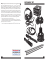
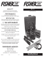
XLT-17
QUALITY
Fisher detectors are renowned for their quality.
Each detector is hand crafted in the USA with pride
Liquid Leak Detector
PERFORMANCE
Treasure Hunters worldwide rely on Fisher.
Our detectors are durable, dependable, and search deeper.
REPUTATION
Fisher produced the first patented metal detector in 1931. For
over 70 years, the Fisher logo has been a mark of excellence.
2 - YEAR LIMITED WARRANTY
Fisher believes in the products we produce and backs this belief
with a 2 year limited warranty, Warranty may vary outside the
United States. See your dealer for details
Proof of purchase is required to make a claim under this warranty.
NOTE TO CUSTOMERS OUTSIDE THE U.S.A.
This warranty may vary in other countries, check with your distributor for details.
Warranty does not cover shipping costs.
According to FCC part 15.21 Changes or Modifications made to this device
not expressly approved by the party responsible for compliance could void
the users authority to operate this equipment.
SERVICE
Fisher is committed to providing you, our valued customer, with
superior service. Each and every instrument is rigidly tested
and carefully inspected during assembly and before shipment.
Should you have any questions or problems, contact:
FISHER RESEARCH LABORATORY
1465-H Henry Brennan,
El Paso, Texas 79936
Tel 915.225.0333 Fax 915.225.0336
www.fisherlab.com email:[email protected]
8700725000
Rev.2
011211
Operating Manual
CONTENTS
Introduction................................................................................. pg. 2
Instrument Set...........................................................................pg. 3-4
Control Panel............................................................................pg. 5-6
Operating Instructions................................................................ pg. 7
Use of the Multi-Sensor................................................................ pg. 8
Specifications.........................................................................pg. 9-10
Warranty........................................................................... Back Cover
INTRODUCTION
Fisher Research Laboratory has always been a leader in the field
of acoustical leak detection. From the early LT-10 through the
XLT-30, high quality sound amplification has been synonymous
with the Fisher name .
Fishers XLT-17 takes leak detection to a new level. The ultra-sensitive
Multi-Sensor, combined with high performance electronics and
crystal clear audio headphones provide a new standard for leak
detection equipment.
2
NOTE: This equipment has been tested and found to comply with the limits
for a Class B digital device pursuant to Part 15 of the FCC Rules. These
limits are designed to provide reasonable protection against harmful
interference in a residential installation. This equipment generates, uses,
and can radiate radio frequency energy and, if not installed and used in
accordance with the instructions, may cause harmful interference to radio
communications. However, there is no guarantee that interference will
not occur in a particular installation. If this equipment does cause harmfill
interference to radio or television reception, which can be determined
by turning the equipment off and on, the user is encouraged to try and
correct the interference by one or more of the following measures:
- Reorient or relocate the receiving antenna.
- Increase the separation between the equipment and the receiver.
- Connect the equipment into an outlet on a circuit different from that
to which the receiver is connected.
- Consult the dealer or an experienced radio/TV technician for help.
INSTRUMENT SET
1
6
7
5
2
4
3
10
3
INSTRUMENT SET
1. Control Box
SPECIFICATIONS
Subject to improvement or modification without notice.
All listening and filtering controls for the XLT-17 are contained in this sturdy
housing. The function of each control is described in the section entitled
“Control Panel.”
Operating Frequency
60 Hz – 6 kHz, Gain = 60 db
20 Hz – 60 Hz, Gain > 55 dB
2. Multi-Sensor
Filter Types and Frequency Ranges:
All Pass:.......................60 Hz to 6 kHz
Low Pass:.....................Adjustable cut-off frequency from 150 Hz to 2.4 kHz
High Pass:....................Adjustable pass band frequency from 150 Hz to 2.4 kHz
Band Pass:..................Adjustable center frequency from 150 Hz to 2.4 kHz
Fisher’s MULTI-SENSOR has superior leak detection capabilities. In an
extremely compact design, the MULTI-SENSOR provides better sensitivity to leaks, improvs audio clarity, improvs sensor electronics, and less
interfering background noise. The MULTI-SENSOR is used for both the
ground microphone and direct contact applications – the one sensor
that does it all.
3. Sound Rods
Two different sizes are included with the XLT-17. Rods give the user various lengths for direct or indirect contact to pipes.
4. Multi-Sensor Handle
This handle is used with the Multi-Sensor
5. Sensor Cable
This cable attaches at the back of the Control Housing to any of the
various sensors, including the Multi-Sensor. Make sure the jack is fully
inserted and the lock nut is hand tightened.
6. Headphones
These headphones are designed to deliver the clearest sound with the
least distortion. The Volume knob can be used to adjust the audio level.
Unplugging the headphones will turn off the XLT-17. (When the XLT-17
is turned off, any modifications to the Volume and Filter will remain at
last settings.)
7. Carrying Strap/Housing Mounting Bracket
The attachment system for the XLT-17 consists of a plastic mounting
bracket that slides from the bottom of the control housing up to the bezel
around the faceplate. There are two slots for attaching an adjustable
strap that hangs around the neck of the user.
4
Output Indications:
Audio...........................High performance headphones (64 ohms)
Visual...........................LCD bargraph and 2-digit numeric display
Grade of Protection........Splash Proof
Battery Test........................Automatic, real time battery level indicator
Battery Quantity/Type.....Two, 9 Volt alkaline
Battery Life........................50 Hours (approximate)
Carrying Case Dimensions
21”x 6”x 14”
Weight:..............................10 lbs
STANDARD EQUIPMENT:
Hard Carrying Case
Operation Manual
Control Unit
Headphones
Muti-Sensor
Carry Strap/Housing Bracket
Sound Rods
Fisher Research Laboratory does not warrant suitability to specific use.
Fisher Research Laboratory shall in no event be liable for any direct, incidental, consequential or indirect damages.
9
Use of the Multi-Sensor
CONTROL PANEL
The multi-sensor was designed for locating leaks in all types of
surface conditions. The new sensor construction will allow leak
detection to be performed on hard surfaces such as concrete,
asphalt, tile, etc, as well as listening to water leaks under turf or
soft surfaces.
On hard surfaces, the mutisensor sensor is used to pick up
the vibrations generated by a
buried ruptured pipe located
underneath sidewalks or paved
streets. The rubber housing
diaphragm is designed to reduce
external sounds while the sensor
rests on a hard surface and
detects the vibrations traveling
underground.
POWER
When utilizing the multi-sensor for
direct connection to a pipe, or
listening to buried pipes located
in soft ground or under a turf
surface, you will need to use the
T-Handle and sound rods included
with the unit. Using a threaded
spacer provided on the extension
handle, carefully attach it directly
onto the Multi-Sensor. Assemble
the T- Handle by snapping both
the extension handle and sensor
handle sections together. Sound
rods are then secured to the
threaded coupler on the T- Handle
assy. Sound rod lengths will be
determined by its application.
8
This keypad turns the XLT-17 on or off. When the instrument is turned
off, all settings are stored in memory and retained for the next time the
XLT-17 is turned on.
VOLUME Arrow KeyPADS
Press Volume arrow keypad, to modify the volume and sensitivity of the
XLT-17. The arrow keys (up arrow/down arrow) increase or decrease the
audio signal to the headphones. Use the headphone volume knob to
reduce audio as desired.
MUTE
As the name applies, muting disengages the sound to the user. There is
also a control on all listening microphones. This keypad should be pressed
when the sensor is moved to prevent excessive noise to your ears.
FREQUENCY Arrow KeyPADS
These keypads allow the frequency range of the XLT-17 audio filters to
be modified.
5
CONTROL PANEL
FILTER
The XLT-17 has four different filtering modes.
AL (All Frequencies) – This is the No Filter feature of the XLT-17. No
modifications to the audio can be made with the arrow keys. Frequency
range of the All Frequency setting is from 60 Hz to 6 kHz. This mode is often
used to begin to listen for the leak noise.
(The following filter modes are often used to pinpoint the location of the
leak noise.)
HI (High Range) – This filtering mode allows the user to adjust the
response in the higher areas of the frequency range. Use the arrow keys
to increase or decrease this frequency response range.
LO (Low Range) – Similar to the previous filter mode, the lowpass
filter allows the user to listen to the lower areas of the frequency range.
The arrow keys are used to increase or decrease this frequency response
range.
FC (Frequency Choice) – This filter could also be called Frequency
Select. This mode allows tuning to the frequency that gives the user the
best audio response to the leak noise. The arrow keys are used to move
the cursor, selecting a narrow frequency band of choice.
6
OPERATING INSTRUCTIONS
Set Up
1. Assemble control housing, headset, and Multi-Sensor. The headset
must be plugged in for the XLT-17 to operate.
2. Familiarize yourself with the location of the mute keypad.
Remember to mute the XLT-17 when moving any sensor.
3. Press POWER keypad to turn on the XLT-17. The XLT-17 goes through
a five second warm up before the touch pads are functional. During
this time, the display screen gives information of battery level. A battery
reading under 5 volts will activate the “Low Battery” indicator. The XLT-17
allows some time between the “Low Battery” indicator and complete
system shut down to allow you to complete a job.
4. The XLT-17 always turns on to the last settings used.
5. Press the VOLUME arrow keys to modify headset volume. Use the ARROW keypads to increase or decrease the volume. The display screen
will show the volume level in a graph form.
6. Begin your leak detection search.
Modifications During Leak Search
Some leaks are small in size, and unrecognizable, or conditions are such
that very little leak sound can be recognized, so you may need to make
changes to the filter(s) in order to hear leaks. Depending upon the type
of pipe composition and soil (ground) type, different filter settings will
increase your ability to hear the leak sound.
Adjustment to the filter is done by pressing the FILTER keypad which will
allow you to scroll through four different filter types. Frequency range
modifications can be made to the HI, LO, and FC filters. As you are
choosing your filter, the display screen will give a visual display of the
filter type being used, and the frequency range of that filter. After your
selection and modification is made, theunit will automatically return to
the operating mode after a 5 second delay.
7
Use of the Multi-Sensor
CONTROL PANEL
The multi-sensor was designed for locating leaks in all types of
surface conditions. The new sensor construction will allow leak
detection to be performed on hard surfaces such as concrete,
asphalt, tile, etc, as well as listening to water leaks under turf or
soft surfaces.
On hard surfaces, the mutisensor sensor is used to pick up
the vibrations generated by a
buried ruptured pipe located
underneath sidewalks or paved
streets. The rubber housing
diaphragm is designed to reduce
external sounds while the sensor
rests on a hard surface and
detects the vibrations traveling
underground.
POWER
When utilizing the multi-sensor for
direct connection to a pipe, or
listening to buried pipes located
in soft ground or under a turf
surface, you will need to use the
T-Handle and sound rods included
with the unit. Using a threaded
spacer provided on the extension
handle, carefully attach it directly
onto the Multi-Sensor. Assemble
the T- Handle by snapping both
the extension handle and sensor
handle sections together. Sound
rods are then secured to the
threaded coupler on the T- Handle
assy. Sound rod lengths will be
determined by its application.
8
This keypad turns the XLT-17 on or off. When the instrument is turned
off, all settings are stored in memory and retained for the next time the
XLT-17 is turned on.
VOLUME Arrow KeyPADS
Press Volume arrow keypad, to modify the volume and sensitivity of the
XLT-17. The arrow keys (up arrow/down arrow) increase or decrease the
audio signal to the headphones. Use the headphone volume knob to
reduce audio as desired.
MUTE
As the name applies, muting disengages the sound to the user. There is
also a control on all listening microphones. This keypad should be pressed
when the sensor is moved to prevent excessive noise to your ears.
FREQUENCY Arrow KeyPADS
These keypads allow the frequency range of the XLT-17 audio filters to
be modified.
5
INSTRUMENT SET
1. Control Box
SPECIFICATIONS
Subject to improvement or modification without notice.
All listening and filtering controls for the XLT-17 are contained in this sturdy
housing. The function of each control is described in the section entitled
“Control Panel.”
Operating Frequency
60 Hz – 6 kHz, Gain = 60 db
20 Hz – 60 Hz, Gain > 55 dB
2. Multi-Sensor
Filter Types and Frequency Ranges:
All Pass:.......................60 Hz to 6 kHz
Low Pass:.....................Adjustable cut-off frequency from 150 Hz to 2.4 kHz
High Pass:....................Adjustable pass band frequency from 150 Hz to 2.4 kHz
Band Pass:..................Adjustable center frequency from 150 Hz to 2.4 kHz
Fisher’s MULTI-SENSOR has superior leak detection capabilities. In an
extremely compact design, the MULTI-SENSOR provides better sensitivity to leaks, improvs audio clarity, improvs sensor electronics, and less
interfering background noise. The MULTI-SENSOR is used for both the
ground microphone and direct contact applications – the one sensor
that does it all.
3. Sound Rods
Two different sizes are included with the XLT-17. Rods give the user various lengths for direct or indirect contact to pipes.
4. Multi-Sensor Handle
This handle is used with the Multi-Sensor
5. Sensor Cable
This cable attaches at the back of the Control Housing to any of the
various sensors, including the Multi-Sensor. Make sure the jack is fully
inserted and the lock nut is hand tightened.
6. Headphones
These headphones are designed to deliver the clearest sound with the
least distortion. The Volume knob can be used to adjust the audio level.
Unplugging the headphones will turn off the XLT-17. (When the XLT-17
is turned off, any modifications to the Volume and Filter will remain at
last settings.)
7. Carrying Strap/Housing Mounting Bracket
The attachment system for the XLT-17 consists of a plastic mounting
bracket that slides from the bottom of the control housing up to the bezel
around the faceplate. There are two slots for attaching an adjustable
strap that hangs around the neck of the user.
4
Output Indications:
Audio...........................High performance headphones (64 ohms)
Visual...........................LCD bargraph and 2-digit numeric display
Grade of Protection........Splash Proof
Battery Test........................Automatic, real time battery level indicator
Battery Quantity/Type.....Two, 9 Volt alkaline
Battery Life........................50 Hours (approximate)
Carrying Case Dimensions
21”x 6”x 14”
Weight:..............................10 lbs
STANDARD EQUIPMENT:
Hard Carrying Case
Operation Manual
Control Unit
Headphones
Muti-Sensor
Carry Strap/Housing Bracket
Sound Rods
Fisher Research Laboratory does not warrant suitability to specific use.
Fisher Research Laboratory shall in no event be liable for any direct, incidental, consequential or indirect damages.
9
NOTE: This equipment has been tested and found to comply with the limits
for a Class B digital device pursuant to Part 15 of the FCC Rules. These
limits are designed to provide reasonable protection against harmful
interference in a residential installation. This equipment generates, uses,
and can radiate radio frequency energy and, if not installed and used in
accordance with the instructions, may cause harmful interference to radio
communications. However, there is no guarantee that interference will
not occur in a particular installation. If this equipment does cause harmfill
interference to radio or television reception, which can be determined
by turning the equipment off and on, the user is encouraged to try and
correct the interference by one or more of the following measures:
- Reorient or relocate the receiving antenna.
- Increase the separation between the equipment and the receiver.
- Connect the equipment into an outlet on a circuit different from that
to which the receiver is connected.
- Consult the dealer or an experienced radio/TV technician for help.
INSTRUMENT SET
1
6
7
5
2
4
3
10
3