1
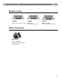
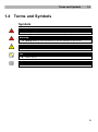
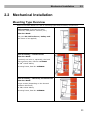
2N® Helios Force 2N® Helios Safety Door Access Intercoms Installation Manual Version 1.0.0 www.2n.cz The 2N TELEKOMUNIKACE a.s. joint-stock company is a Czech manufacturer and supplier of telecommunications equipment. The product family developed by 2N TELEKOMUNIKACE a.s. includes intercoms, GSM and UMTS products, private branch exchanges (PBXs) and M2M solution. 2N TELEKOMUNIKACE a.s. has been ranked among the Czech top companies for years and represents a symbol of prosperity in the field of intercoms. Furthermore, the company dedicates significant attention to operator solutions as well as to effectively providing support for our distribution network and customer service. At present, we export our products into over 120 countries worldwide and have exclusive distributors on all continents. 2N® is a registered trademark of 2N TELEKOMUNIKACE a.s.. Any product and/or other names mentioned herein are registered trademarks and/or trademarks or brands protected by law. 2N TELEKOMUNIKACE administers the FAQ database to help you quickly find information and to answer your questions about 2N products and services. On faq.2n.cz you can find information regarding products adjustment and instructions for optimum use and procedures „What to do if...“. Declaration of Conformity 2N TELEKOMUNIKACE a.s. hereby declares that the 2N® Helios Force and 2N® Helios Safety products complies with all basic requirements and other relevant provisions of the 1999/5/EC directive. For the full wording of the Declaration of Conformity see the CD-ROM enclosed and at www.2n.cz. 2N TELEKOMUNIKACE company is the owner of the ISO 9001:2008 certificate. All development, production and distribution processes of the company are managed by this standard and guarantee high quality, technical level and professional aspect of all our products. Contents 1. Product Overview............................................................... 1 1.1 Product Description ....................................................................................................... 2 Basic Features.................................................................................................................. 2 Advantages of Use ........................................................................................................... 3 1.2 Upgrade ........................................................................................................................... 4 1.3 2N Helios Force / Safety Components and Associated Products ........................... 5 Basic Units ........................................................................................................................ 5 Flush Mounting Box, Frame ............................................................................................. 6 GSM and VOIP Connection Accessories ......................................................................... 6 Electric Locks ................................................................................................................... 7 Other Accesories .............................................................................................................. 7 1.4 Terms and Symbols ....................................................................................................... 8 Symbols ............................................................................................................................ 8 ® 2. Description and Installation .............................................. 9 2.1 Before You Start ........................................................................................................... 10 Product Completeness Check ........................................................................................ 10 2.2 Mechanical Installation ................................................................................................ 11 Mounting Type Overview ................................................................................................ 11 Common Mounting Principles ........................................................................................ 13 Wall Mounting ................................................................................................................. 14 Flush Mounting – Classic Bricks .................................................................................... 15 Flush Mounting – Thermally Insulated Wall ................................................................... 16 Flush Mounting – Hollow Bricks ..................................................................................... 17 Flush Mounting – Plasterboard ...................................................................................... 17 Use of Cable Bushings ................................................................................................... 18 2.3 Electric Installation ...................................................................................................... 19 PCB Connectors ............................................................................................................. 19 Compatibility ................................................................................................................... 20 Connection to Telephone Line ....................................................................................... 20 External Power Supply and Electric Lock Connection ................................................... 21 Mounting Completion ..................................................................................................... 22 2.4 Button Tags – Insertion and Replacement - 2N® Helios Force only....................... 23 Tag Printing .................................................................................................................... 23 Tag Inserting / Replacing Instructions ............................................................................ 23 3. Programming and Use ..................................................... 25 3.1 Programming ................................................................................................................ 26 Entering Programming Mode ......................................................................................... 26 Programming Procedure ................................................................................................ 26 Programming Error ......................................................................................................... 27 Deleting All Passwords, All Memories, Complete Initialisation ...................................... 28 If You Forget the Service Password ............................................................................... 28 3.2 Full Parameter Chart .................................................................................................... 29 Explanation of Some Parameters................................................................................... 33 3.3 Function Description ................................................................................................... 34 From External User's View (Visitor) ............................................................................... 34 Function Description – Numerical Keypad Models ........................................................ 34 From Internal User's View (Survey of Functions) ........................................................... 35 Signals Overview ............................................................................................................ 36 Call Termination Options - Summary ............................................................................. 37 Code Lock ...................................................................................................................... 37 Traditional Telephone ..................................................................................................... 38 DTMF Transmission during Outgoing Call ..................................................................... 38 Buttons Substitution ....................................................................................................... 38 Keypad Operation Instructions - Summary .................................................................... 39 Frequently Asked Questions About Keypad Function.................................................... 40 Intercom Statuses and Available Operations ................................................................. 41 3.4 Section for Advanced Users ....................................................................................... 42 Automatic Multiple Number Dialling ............................................................................... 42 Survey of Messages ....................................................................................................... 45 Arrival/Departure, Day/Night Modes............................................................................... 46 3.5 Maintenance .................................................................................................................. 47 Cleaning ......................................................................................................................... 47 Future Tag Replacement, Programming Changes ........................................................ 47 4. Technical Parameters ...................................................... 49 4.1 Technical Parameters .................................................................................................. 51 5. Supplementary Information ............................................ 53 5.1 Directives, Laws and Regulations .............................................................................. 54 5.2 Troubleshooting ........................................................................................................... 55 5.3 General Instructions and Cautions ............................................................................ 56 Electric Waste and Used Battery Pack Handling ........................................................... 57 1 1. Product Overview In this section, we introduce the 2N® Helios Force and 2N® Helios Safety products, outline its application options and highlight the advantages following from its use. Here is what you can find in this section: Product Description Upgrade 2N® Helios Force / Safety Components and Associated Products Terms and Symbols 1 Product Description 1.1 1.1 Product Description Basic Features 2N® Helios Force / Safety is a highly resistant and reliable door access intercom provided with a lot of useful above-standard functions. 2N® Helios Force / Safety can work as a standard or emergency door access intercom for buildings, entrances to premises or garages, manufacturing halls, highways and so on. 2N® Helios Force / Safety is equipped with additional, 0.5 Watt audio amplifier. Without power supply, amplifier is bypassed and intercom is powered by telephone line. 2N® Helios Force / Safety can be provided with 1, 2 or 4 pre-programmed buttons. You can set up to six telephone numbers for each of the buttons to increase the accessibility of the called party. 2N® Helios Force can be equipped with a numerical keypad to be used as a code lock for lock switch activating or telephone/subscriber number dialling. 2N® Helios Force / Safety is equipped with an electric lock switch. You can control the switch using a numerical keypad or, during a call, using any telephone set. An additional switch module can be installed if necessary. A wide range of settings allow for a variety of applications. 2N® Helios Force / Safety is very easy to install. All you have to do is connect the system into your PBX and feed it from a 12V power supply. 2N® Helios Force / Safety programming is easy, voice menu based, via telephone. 2 Product Description 1.1 Advantages of Use Uncompromising AntiVandal design Variable mounting options (brick/plasterboard flush mounting, surface mounting) Sensitive microphone and powerful loudspeaker Dial buttons including name tags and backlight (2N® Helios Force) Optional numerical keypad with backlight (2N® Helios Force) Integrated electronic lock switches with wide setting options Configuration via phone (voice menu based) Operates on any analogue telephone line Stable line power feeding High acoustic quality Special functions includes automatic dialling of multiple numbers, silent dialling, departure/arrival, day/night mode, second switch delay 3 Upgrade 1.2 1.2 Upgrade The manufacturer reserves the right to modify the product in order to improve its qualities. Version Changes 4 2N® Helios Force / Safety Components and Associated Products 1.3 1.3 2N® Helios Force / Safety Components and Associated Products Basic Units 9151201-E ® 9151201K-E ® 9151204-E ® 9152101-E 2N Helios Force 2N Helios Force 2N Helios Force 2N® Helios Safety 1 button 1 button with keypad 4 buttons 1 button 2N® Helios Force / Safety is designed for outdoor applications and requires no additional roof. 2N® Helios Force units can be flush or wall mounted without requiring any additional accessories. Use the appropriate mounting box (see below) for plasterboard and hollow brick flush mounting. 2N® Helios Safety units can be wall mounted (frame is not included, but can be ordered separately). 5 2N® Helios Force / Safety Components and Associated Products 1.3 Flush Mounting Box, Frame 9151001 9151002 9152000 Brick flush mounting box Plasterboard flush mounting box Mounting frame orange Aluminum GSM and VOIP Connection Accessories EasyGate GSM gateway Part No. 501303E Analogue/VoIP gateway Part No. 91341711E 6 2N® Helios Force / Safety Components and Associated Products 1.3 Electric Locks 932070 932080 932090 BEFO 1211 12V / 600 mA BEFO 1221 with momentary pin BEFO 1211MB with mechanical blocking Other Accesories 91341481E 12 V/2 A adapter Note: AC power supply is not applicable. 7 Terms and Symbols 1.4 1.4 Terms and Symbols Symbols Safety Warning Always abide by this information to prevent injury of persons! Warning Always abide by this information to prevent damage to the device. Caution Important information for system functionality. Tip Useful advice. Note Additional information. 8 2 2. Description and Installation In this section we describe the 2N® Helios Force / Safety products and its installation. Here is what you can find in this section: Before You Start Mechanical Installation Button Tags – Insertion and Replacement Electric Installation 9 Before You Start 2.1 2.1 Before You Start Product Completeness Check Please check the contents of your 2N® Helios Force / Safety delivery: 1 2N® Helios Force / Safety (selected model) 1 frame (2N® Helios Force only) 1 Torx 10 / Torx 20 double-ended wrench Bushings (enclosed): 1 big two-hole sealed bushing with nut 1 spare sealing for big bushing for a thick cable, one hole 1 big blank with nut 1 small bushing with nut 1 bushing plug, big size 2 bushing plugs, small size 1 2N® Helios Force / Safety Brief Manual 1 mounting template 1 CD 1 A5 transparent name plate foil 1 spare name tag 4 5x90 mm screws 4 “intelligent” 8x50 mm dowels 10 Mechanical Installation 2.2 2.2 Mechanical Installation Mounting Type Overview Refer to the table below for a list of mounting types and necessary components. Wall mounting (concrete and steel structures, entry barrier columns, etc.) What You Need: Just your 2N® Helios Force / Safety unit (the frame is not applied) Flush mounting – classic bricks What You Need: A precisely cut hole or, optionally, the brick flush mounting box, Part No. 9151001 For 2N® Helios Safety: Mounting frame, Part No. 9152000 Flush mounting – thermally insulated wall What You Need: Longer screws (depending on the thermal insulation thickness) For 2N® Helios Safety: Mounting frame, Part No. 9152000 11 Mechanical Installation 2.2 Flush mounting – hollow bricks What You Need: Brick flush mounting box, Part No. 9151001 For 2N® Helios Safety: Mounting frame, Part No. 9152000 Flush mounting – plasterboard wall What You Need: Plasterboard flush mounting box, Part No. 9151002 For 2N® Helios Safety: Mounting frame, Part No. 9152000 Caution The warranty does not apply to the product defects and failures arisen as a result of improper mounting (in contradiction herewith). The manufacturer is neither liable for damages caused by theft within an area that is accessible after the attached electric lock is switched. The product is not designed as a burglar protection device except when used in combination with a standard lock, which has the security function. When the proper mounting instructions are not met, water might get in and destroy the electronics. It is because the intercom circuits are under continuous voltage and water infiltration causes an electro-chemical reaction. The manufacturer’s warranty shall be void for products damaged in this way! 12 Mechanical Installation 2.2 Common Mounting Principles Tips Select flush mounting where possible to make your product elegant looking, more vandal resistant and more secure. You can purchase the flush mounting box in advance and hire an installation professional to make the basic installation work. Moreover, the mounting box helps you align the intercom vertically (with a deviation of up to 2°). Caution Make sure that the dowel holes have the required diameter. If the diameter is too large, the dowels may get loose. Use some suitable building adhesive to keep the dowels in place. Make sure that the hole depth is sufficient too! The dowel length is 50 mm and the screw length is 90 mm. Remember that dowels of poor quality may easily get loose and fall out of the wall! Stainless steel screws are used for the 2N® Helios Force / Safety assembly. Other screws than stainless steel ones corrode soon and may aesthetically deteriorate the surrounding environment! Having removed the front panel, make sure that no dirt gets inside the product (especially onto the sealing surface and microphone sound guides). Note The microphone sound guides are normally loose after the front panel is removed! The screw is only used as a fall-out protection during installation. 13 Mechanical Installation 2.2 Wall Mounting Wall (surface) mounting is used where flush mounting is inapplicable (in concrete and steel structures, entry barrier columns, etc.). The frame is not used. Caution Wall mounting may be a problem where vandals may destroy the unit (in public garages, e.g.). Therefore, use steel fixing elements instead of the dowels and screws included in the delivery. Be sure to insert plugs into unused bushing holes to avoid water leakage during facade cleaning, for example. Never leave the holes open for even a short time (one day delay between mounting and cable connection, e.g.). Safety Warning Eliminate the risk of accident! Wall mounting is not suitable for narrow passages or places where people’s attention may be distracted. The manufacturer shall not be liable for injuries incurred as a result of unsafe mounting! 1. Select the 2N® Helios Force / Safety position with respect to the supply cables. Where the cables are installed inside a structure or wall, use the hole at the intercom bottom. 2. Drill holes of the depth of 70 mm for dowels in the wall as shown in the figure. Push or hammer the enclosed dowels into the drilled holes. Use some suitable building adhesive if the dowels are too loose. Use fixing elements of your own for steel structure surface mounting (metric screws + nuts, e.g.). 3. Remove the front panel from the intercom. The electronic parts of the two bottom buttons remain on the panel in the four-name plate version. 4. Select the holes for cable supply. Select and mount the bushings depending on the cables: 2-hole bushing or 1-hole bushing or both. Insert the blanks in the other holes. 5. Put the intercom on the wall/structure while introducing cables inside. Leave some of the cables inside the unit as a reserve. Insert the plugs in the unused bushings and tighten the bushing nuts carefully. 6. Do not complete mounting until you have finished electrical installation – refer to Mounting Completion. Where cables lead along the surface, use the bushings included in the delivery. 14 Mechanical Installation 2.2 Flush Mounting – Classic Bricks If you use the brick flush mounting box, follow the instructions included in the box. If you do not use the mounting box, follow the instructions below: 1. Make a hole using the template. Suppose that all the required cables have been carried into the hole. 2. Unpack the frame, put the intercom inside and place the set onto the hole to make sure that the hole is deep enough and the uneven edge is perfectly covered with the frame. 3. Push or hammer the enclosed dowels into the drilled holes. Use some suitable building adhesive if the dowels are too loose. 4. Remove the front panel from the intercom. The electronic parts of the two bottom buttons remain on the panel in the fourname plate version. 5. Select the holes for cable supply. Insert the blanks into the other holes. Apply the cable bushings or a suitable sealant to prevent penetration of insects or water. You can also insert the small bushing in the intercom bottom hole. make sure that the dowel holes are drilled accurately! You will not be able to align considerable inaccuracies with this way of mounting! 6. Put the frame on the intercom. 7. Place the intercom into the hole while introducing the cables. Leave some of the cables inside the unit as a reserve and the rest under the intercom bottom. 8. Insert the enclosed screws in the lateral mounting holes making sure they have penetrated into the dowels. Tighten all the screws properly. Tip: The screw tightening sequence may affect the intercom position. 9. You can seal the frame - wall gap with a silicone or another sealant to avoid wall dampening as a result of water leakage. This additional sealing is unnecessary for the intercom function. 10. Do not complete mounting until you have finished electrical installation – refer to Mounting Completion 15 Mechanical Installation 2.2 Flush Mounting – Thermally Insulated Wall Cut out the thermal insulation layer using the template (the same as for classic brick wall). Caution The hole depth depends on the insulation layer thickness. If the insulation layer is rather thick, you may need longer screws! If there are hollow bricks under the insulation, make sure that your screws pass through the whole dowel (50 mm) and fix the dowel reliably. Make sure that the dowel holes have the required diameter. If the diameter is too large, the dowels may get loose. Use some suitable building adhesive to keep the dowels in place. Make sure that the hole depth is sufficient too! The dowel length is 50 mm and the screw length is 90 mm. Suppose that all the required cables have been carried into the drilled hole. Now follow the instructions applicable for classic brick flush mounting. However, remember that thermally insulated walls show less strength than classic brick walls. 16 Mechanical Installation 2.2 Flush Mounting – Hollow Bricks Suppose you intend to install your 2N® Helios Force / Safety unit into a wall made of hollow bricks. Note that the external side of the bricks gets damaged by cutting and the dowels cannot practically be fixed into the thin internal part of the bricks. Therefore, use the brick flush mounting box and follow the instructions included therein. Flush Mounting – Plasterboard Use the plasterboard flush mounting box and follow the instructions included therein. 17 Mechanical Installation 2.2 Use of Cable Bushings The cable bushings included in the 2N® Helios Force / Safety delivery are designed for the following cables: Big bushing: for two cables of the diameter of 5–6 mm (UTP cable), or, upon insert replacement, for one thick cable/tube of the diameter of up to 14 mm. Small bushing: for one cable of the diameter of 5–8 mm. Tip Even a LAN cable including the RJ-45 connector can go through the big bushing. See below for instructions. How to Pull a RJ-45 Terminated Cable through a Bushing 1. Unscrew the big bushing nut completely. 2. Remove the sealing including the cover from the bushing. Cut either of the components as shown in the figures. 3. Put the bushing nut on the cable and insert the sealing. 4. Replace the cover onto the sealing. 5. Pull the cable connector though the bushing body into the intercom and clip it into the motherboard connector. 6. Move the sealing including the cover along the cable as far as the bushing body, or add a plug if necessary. 7. Replace and tighten the nut. 18 Electric Installation 2.3 2.3 Electric Installation This subsection describes how to connect 2N® Helios Force / Safety to your PBX and how to connect supply voltage and the electric lock. PCB Connectors Fig. 2.11 shows the lay-out of connectors on the 2N® Helios Force / Safety printed circuit board (PCB). Figure 2.11 2N® Helios Force / Safety Connectors, PCB Version 3 19 Electric Installation 2.3 Description of Connectors 1 Loudspeaker connector 2 To pushbuttons 3 Microphone sensitivity attenuator: 4 Microphone connector 5 Line connection: RJ-12 or screw terminals 6 DC power 12V for power amplifier and for backlight 7 Protecting ground 8 Switch output 9 Additional switch 10 To keypad 11 Servicing connector 12 Power amplifier bypass: 13 Power amplifier volume adjustment high (normal) Amplifier ON low OFF (bypassed) Compatibility 2N® Helios Force / Safety is designed for conventional, analogue telephone lines and works regardless of polarity and line parameters (Refer to the Technical Parameters) and uses tone (DTMF) dialling to be programmed. Normally, it is connected to a PBX line. However, it can also be connected to CO line or the GSM gateway, providing a wireless connectivity. Connection to Telephone Line Connect 2N® Helios Force / Safety simply using LINE terminals – RJ connector or terminal block. The advantage is that 2N® Helios Force / Safety requires no power supply because all power is fed from the telephone line – except for the amplifier, button backlight and electric lock, if connected. Nevertheless, 2N® Helios Force / Safety can work without these circuits too (amplifier is bypassed in this case). 2N® Helios Force / Safety sends an acoustic signal on having been connected to a line (or after having been disconnected from the line for a defined period of time). 20 Electric Installation 2.3 External Power Supply and Electric Lock Connection 2N® Helios Force / Safety require 12V (DC only!) supply for: 1. Built-in audio amplifier – current draw of up to 100 mA, 2. Name tag and keypad backlight – current draw of up to 150 mA 3. Electric lock – current draw according to the lock type The electric lock can be fed from the same source as the intercom or another supply. 2N® Helios Force / Safety contains a solid-state switch, which is able to switch both AC and DC regardless of polarity. Make sure that the current and voltage values do not exceed limits (refer to the Technical Data) and that the technical parameters of the lock and power supply are compatible. Danger! Never switch 230 or 120 V mains voltage directly!!! Caution If the lock power supply fails and the telephone system carries on working, the intercom is unaware of the failure the switch will be password-activated and the activation is acoustically signalled, but the electric lock will not work because of the lack of power. Ground connection is mandatory. If used power supply output is grounded, you can connect GND terminal to it. Electric Lock Connection Make sure that the power supply is able to supply the required current. Connect the supply and lock as shown in the figure: 21 Electric Installation 2.3 Separate Backlight and Electric Lock Supply Separate power supplies are necessary e.g. where the lock requires voltage higher than 12 V. In this case, an additional power supply (12V) must be used to illuminate the button backlight - see the figure below: Mounting Completion 1. Having connected all the wires, make sure that the bushings, if used, are tightened properly and the RJ-45 connector is inserted in the PCB connector (if used). 2. Replace the front cover carefully. Make sure that the wires inside the device leave enough space for the front cover assembly. Tighten the four screws thoroughly with the wrench enclosed (Torx 20) to make the panel fit tightly to the metal chassis. Caution An incorrect mounting may compromise the intercom water tightness. Water leakage may damage the electronic part of the system. Stainless steel screws are used for the 2N® Helios Force / Safety assembly. Other screws than stainless steel ones corrode soon and may aesthetically deteriorate the surrounding environment! 22 Button Tags – Insertion and Replacement - 2N® Helios Force only 2.4 2.4 Button Tags – Insertion and Replacement - 2N® Helios Force only Tag Printing 1. Every 2N® Helios Force delivery includes a sheet of translucent foil, which can be laser-printed. Cut the printed foil and insert the tags in the name plates. 2. Every name plate includes a piece of foil, which can be written over manually, using a waterproof permanent marker, if necessary. Note Always use waterproof foil (enclosed or other) for the tags. Never use paper or ink jet printing to avoid damage due to water leakage! Tag Inserting / Replacing Instructions 2N® Helios Force provides an intuitive, easy access to the name plates. The tags are easy to insert and replace even without a manual. You need not remove the front panel and thus are not exposed to the risk of loss of components while replacing the tags. 1. Loosen the name plate screw using the wrench enclosed, for example. You can open the name plate window like a door without losing the tightened screw. 2. Remove the used or blank name tag and insert a new tag. 2. Close the name plate window and tighten the screw appropriately. 3. Check the click effect of the buttons: if the button fails to click properly when pressed (when moved by approx. 0.5 mm), the tag is too thick or thin. Make sure that the button clicks when you press it on both ends. 23 3 3. Programming and Use In this section we describe the basic and extending functions of the 2N® Helios Force / Safety product. Here is what you can find in this section: Programming Full Parameter Chart Function Description Section for Advanced Users Maintenance 25 Programming 3.1 3.1 Programming All the intercom parameters, including the keypad ones, are set remotely using any tone-dialling telephone set (or a mobile phone). First call the intercom and enter the programming mode. The access to this mode is service password protected. A voice menu is available in the programming mode and so you need not use this manual to program standard parameters. The menu is stored in the intercom memory in the default language. Having entered the full parameter or memory number, you can hear how the parameter has been programmed, thus checking the programmed numbers for correctness. All parameters are stored safely in the non-volatile EEPROM memory. Tip – Before You Start Programming Write or print the values to be programmed to minimise the risk of error. Moreover, this gives you an idea of what you have programmed. Make sure that programming is not barred (JP1 jumper) – refer to the PCB Description subsection. Entering Programming Mode You can enter the programming mode only during an incoming call (telephone – intercom call). The programming barring jumper must not be mounted. To get into the programming mode, enter the service password in the format password (do not forget to enter the asterisks before and behind the password!). The service password is 12345 by default and can be changed. If you enter the password correctly, the voice menu is launched. Now you can start programming. Programming Procedure You can set parameters in any order and as many times as you wish. To change a parameter use the following command: Parameter number parameter value A three-digit parameter number is assigned to every parameter to be programmed and to every memory (refer to the Programming Chart). This number indicates to the intercom which parameter to change, and is used as "Enter". When it is entered, the intercom repeats the parameter (or memory) number and reads the current contents (excluding passwords). Now you can enter new data – of variable meaning and length depending on the parameter selected (refer to the Full Parameter Chart). Finally, press again for confirmation. The intercom confirms the data saving. Repeat this procedure for each parameter. Switch Password Programming Each switch can be controlled with up to 10 different passwords that are listed in the intercom memory. Passwords can be added to the list using function 811 and deleted 26 Programming 3.1 with function 812 individually. The default status is a single password in the list, namely 00 for switch 1. This special password cannot be entered from the intercom keypad. To cancel them, you have to remove them from the list: Function 997 deletes the entire password list including the password 00. Function 999 deletes the entire password list too but recovers the password 00 and the service password 12345. Password Selection Restrictions Controlling the switch by phone, you can enter the password without any starting and terminating characters and the password length is not limited. The intercom has to verify after every character received whether the password is complete or not. Therefore: make sure that no password is identical with the beginning of another password. Should you use such confusing passwords for switch control, you have to enter the longer password (by phone) with asterisks at the beginning and end. If the intercom refuses to store a password, it means that the switch password list is full, or the password has already been entered. The switch password may not be identical with any Arrival/Departure, Day/Night, or service password. For password selection tips see the Instructions for Keypad Use. Programming Error Any wrong value can be re-programmed (immediately or any time later). by another command If you make a typing error, cancel the entered value with re-enter the whole number. If you enter an incorrect parameter number or parameter value, the intercom sends a refusal signal and you have to start with the parameter number again. If you do not press any button within a predefined timeout, the intercom sends a hang-up signal and hangs up. The timeout is 5 seconds; every character is followed by 30 seconds for you to think over your setting. The 5-second limit starts when the intercom has read all that relates to the current user position in the programming menu. The timeout can be prolonged – see the chart. . Then you can Tip To check programmed values: enter parameter number and the parameter value and press for return to the main menu. , listen 27 Programming 3.1 Deleting All Passwords, All Memories, Complete Initialisation The following three functions facilitate your programming by clearing all previous settings: 997 deletes the entire password list for switch including password 00. 998 deletes memories of all buttons (01 - 02) plus Arrival/Departure and Day/Night passwords. 999 clears the whole memory and resets the default values (see the chart). Protection against Unintentional Deletion The above functions need no special "value" but must be protected against unintentional initiation. Therefore, enter the service password as the value. Warning: Full initialisation takes a few seconds, the intercom sends a continuous tone while memory clearing. Functions 997 and 998 take a little less time and are signalled by a continuous tone too. The button memories can be deleted individually too – just enter a “blank” while programming. For example: clears memory 1 of button 01. If You Forget the Service Password If you forget the service password, contact the manufacturer. The manufacturer can change your service password to 12345 remotely without altering any other parameter. Password Selection Tip Keyboard letters facilitate password remembering. For example, it is easier to remember a 9-letter word (e.g. crocodile) than a 9-digit number (276263453). 28 Full Parameter Chart 3.2 3.2 Full Parameter Chart Parameter Parameter Name (function) 011 to 016 ... 011 to 046 Button 01 memories ... Button 04 memories Range Default Note Up to 16 digits blank ... ... Up to 16 digits blank Note 1: Button number 05 – 54 can be used to store pre-programmed numbers, accessable via keypad (enable parameter 922) Digits 0-9 can only be entered directly into the memories. Special characters are entered additionally using function XX7: 017 ... 047 Enter special chars , and pause Button numbers 05 – 54: see note 1 above. 018 ... 048 Button 01 to 04 count of automatic dialling cycles 019 ... 049 Button 01 to 04 Arrival/Departure password up to 16 digits blank 559 Day/Night password up to 16 digits blank The same as for Arrival/ Departure, identical for all buttons 811 Enter up to 10 switch passwords up to 16 digits 00 Password 00 cannot be entered from the keypad! Up to 10 switch passwords Delete passwords using function 812 812 Delete valid switch passwords Valid password 813 Switch closing time 0-9 s 5s 901 Dialling type 0-1 0= tone 0-9 0 = off Button numbers 05 – 54: see note 1 above. Button numbers 05 – 54: see note 1 above. Deletes individual valid switch passwords. 0 = switch disabled 1=pulse 40/60 29 Full Parameter Chart Parameter Parameter Name (function) 3.2 Range Default Note 902 Dialling timeout after pick-up 5-99 8= 0.8s 903 DTMF transmitting level 0-12 6 904 Automatic Multiple Number Dialling type 0-3 0= disabled for all buttons 906 Ticking into call 911 Count of rings before incoming call answering 1-99 912 Max. call duration 1-99 12 = 120s 913 Log-in timeout 1-99 3 915 Hang-up time between calls 5-99 15 = 1.5 s 921 Code lock mode 0-1 1= enabled 922 Buttons replaced by keypad 0-1 0= 0 = disabled disabled 1 = enabled 923 Telephone mode 0-1 For details on these functions see the 0= disabled Keypad Description. 924 Tone dialling during call 0-1 0= disabled 931 Microphone powerup level 0-3 2 0 = Maximum microphone sensitivity 932 Automatic response speed 0-3 2 3 = Maximum response speed 933 Reception volume 0-15 7 15 = Maximum reception volume 934 Transmission volume 0-15 7 15 = Maximum transmission volume 935 Message volume 0-15 7 15 = Maximum message volume 936 Beeping volume 0-12 12 12 = Maximum tone volume 937 DTMF hearing (side 0-3 tone) volume 3 3 = Maximum DTMF volume 938 Loudspeaker volume 7 15 = Maximum loudspeaker volume 941 Minimum continuous tone 0-12 10 99 1 step = 1 dB 1 2 3 4 = = = = loud with confirmation silent with confirmation SP without confirmation 1) SP without confirmation 1) The called party recognises better 0 = off that the incoming call is from the intercom. 2 0-15 Range of 0.5 - 9.9s 20 = 2s Warning!!! No connection is established if a higher value is entered than as allowed in the PBX ringing timeout!!! Range of 10s-990s 3 = 30 seconds If the tone is longer, the intercom hangs up. 30 Full Parameter Chart Parameter Parameter Name (function) 3.2 Range Default Note time 942 Minimum busy tone or pause duration 0-255 8= 0.08s 943 Maximum busy tone or pause duration 0-255 70 = 0.7s 944 Maximum tonepause difference 0-255 10 = 0.1s 945 Minimum count of busy tone periods 2-9 4 946 Dual tone detection setting These parameters control the busy tone detection. They are used for call termination and automatic dialling. All continuous, busy and ringing tones are detected. Dual tones are detected if one of their components is between 400 and 500 Hz. If both components are in this range, set a lower 4= 0 – 10 440 Hz detection value. Set 0 for 400 Hz and 10 for 500 Hz. This setting does not affect the single tone detection, which always works between 300 and 550 Hz. 951 Minimum ringing tone time 1200 952 Minimum long pause time 5100 953 Maximum long pause time 10 100 Count of ringing periods 954 1 - 99 50 = The longest ringing period pause 0,5 s 2) must be in the interval between parameters 952 and 953. 10 = 1 Warning! As these parameters s also detect incoming calls, an 60 = 6 incorrect setting may result in s the intercom not answering the call! 10 If the preset count of periods is exceeded, the call is terminated. If the preset count of periods is exceeded and automatic dialling is enabled, another attempt follows. In the event of Automatic Dialling without Confirmation, the ringing tone is recognised and ends before the preset count of periods is exhausted; the call is regarded as successful. 961 Maximum timeout for pressing the next digit 963 Possibility to hang up by pressing the same button 964 Possibility to dial the next number by pressing 2nd button 971 Count of message repetitions 1-9 0 = no 1 = yes 0 = no 1 = yes 0-9 5s During password entering, etc. 1 1 3 There is a 3-second pause between every two messages. 31 Full Parameter Chart Parameter Parameter Name (function) Intercom identification number 974 3.2 Range Default Note 16 digits - 1st digit = type of message repeated after dialling. 2nd digit = type of message after confirmation. The following digits are used: 2 = identification (974) - loud speaking 4 = identification (974) - DTMF 5 = message as defined in par. 977 (after confirmation by par. 976) 7 = confirming tone (after confirmation only) 975 Message options for automatic multiple number dialling 2 digits 976 language selection for a message 0-8 1 977 language selection for "wait, please" message 0-8 1 991 Service password 995 Software version identification 997 Deletion of all switch passwords 998 Clearing of all memories 999 Full initialisation 55 12345 0= 1 = English 2-3= 4 = German 5-7= 8 = Portuguese 9 = Dutch 10 ... 99 = silence Note: See Survey of messages in Subs. 4.2 Caution! Czech version has language order: 1 = Czech, 2 = English 12345 by default This function reads out the current software version. Format: yearmonth-day. Writing disable. - Service passwor d The number enables intercom identification. 12345 Deletes password 00 too. 12345 Clears memories 01 to 55. 12345 Warning! Changes the service password too (setting the default value of 12345). Notes Terminology: For the purpose hereof, parameter means a value that is stored in the intercom memory and can be re-programmed. Function is a means of execution of another service such as initialisation, software version identification and so on. 1 ) Types 3 and 4 of Automatic Dialling without Confirmation differ from each other in how they process very short calls (a few seconds). Dialling type 4 regards a call as successful in all cases, type 3 only if the door was opened. 32 Full Parameter Chart 3.2 Explanation of Some Parameters Explanation of Parameters 951, 952, 953 Ringing tone (example) Ringing tone At this time Helios detects, that ringing tone had ended. Long pause Par. 952 Par. 953 Par. 953 Explanation of Parameters 942, 943, 944 Busy tone tone time pause time par. 942 par. 943 Example: The busy tone in the figure above is considerably longer than the pause time. Therefore, set parameter 942 according to the pause, to 200 ms, e.g., and parameter 943 according to the tone, to 600 ms, for example. In this case, however, the default values can be maintained for both the parameters. Since the tone – pause difference is 500 – 250 = 250 ms, set parameter 944 to 300 ms, for example. Note Increase parameter 944 also when the intercom is placed in a hall or corridor with a large decay time. 33 Function Description 3.3 3.3 Function Description From External User's View (Visitor) Like normal doorbells, intercom buttons are provided with labels. The visitor finds the appropriate button (e.g. Mr. Smith) and presses it. This activates the intercom, which then dials the number pre-programmed for that button, The visitor can then hear the ringing tone from the loudspeaker and the required (Mr. Smith’s in this case) telephone is ringing. If the intercom is connected to a telephone system, you can tag the port the intercom is connected to in order to see on the ringing phone that it is the intercom that is calling. When the called party answers the call, the visitor and the called person can speak to each other and, if an electric lock is connected to the intercom, the called person can open the door by entering the correct password on the telephone keypad to activate the door or barrier. When the caller hangs up, the intercom detects the PBX or analogue line tone and hangs up too. The intercom also hangs up when it “hears” the busy tone or if the call takes more time than as preprogrammed to connect. You can pre-program the amount of time that you have to speak into the microphone, but when you reach the programmed time, the unit will send a warning tone 10 seconds before hanging up so that the called party can extend the call if required. Note If the visitor presses another button during the call, the intercom hangs up for a few seconds before dialling the new number. If a button is pressed that has no number stored within it, the intercom picks up the line, sends a refusal tone (refer to the Signals Overview) and hangs up. If the visitor presses the same button during the call, the intercom may hang up (can be programmed to stop this feature if required). The above mentioned rules are only applied if the Automatic Multiple Number Dialling mode is OFF. For this special mode refer to the Automatic Multiple Number Dialling section. Function Description – Numerical Keypad Models 2N® Helios Force model 9151201K-E is equipped with a numerical keypad. The keypad provides a number of functions: traditional code lock features as if a normal telephone set DTMF transmission during an outgoing call substitution of up to 54 buttons The keypad features a smart metal design and very favourable price to performance ratio. For the description of the functions from the user‘s view see below. 34 Function Description 3.3 From Internal User's View (Survey of Functions) Calling to 2N® Helios Force / Safety You call the appropriate extension and the intercom makes the call and gives a confirmation tone after two rings (or as pre-programmed). Now you can speak and control the switch, program the intercom (see later), and listen to what is going on outside and speak to the calling party if desired. Door opening The intercom contains a switch to which an electric lock can be connected (not included in this pack). This switch can be telephone keypad controlled using a (digital) password in two ways as shown in the default password 00 example below: or The switch activation time can be programmed once the switch is enabled this will also automatically terminate the call in the next 30 seconds. Note If the Automatic Multiple Number Dialling with Confirmation or the Silent Automatic Multiple Number Dialling with Confirmation mode is selected and the password starts with digits 1 to 5, an asterisk must always be used. You Must enter every digit in the password within five seconds (or as preprogrammed) to avoid the intercom hanging up. Switch 2 activation (light, e.g.) The second switch (if an additional switch is installed) can be controlled in the same way, default password is 11. Switch 2 synchronisation Switch 2 can also be used to delay the opening of another door. Once the switch 2 delay timeout is programmed, the second switch is synchronised automatically with the first one, the delay being 1 – 25 seconds. Switch activation signalling (for both switches) After the correct password is entered, the switch is activated and you can hear the confirmation signal on your telephone. You can now speak (e.g. say: “The door is open”) or listen (to the door-opening sound, etc.) until the switch is deactivated. Upon deactivation, you can hear the storing signal (see the Signals Overview). 35 Function Description 3.3 Call extension The intercom beeps 10 seconds before the call end. To extend the call by 30 seconds press on your telephone (DTMF). You can use this function repeatedly. The visitor, however, cannot use this function! Programming The access to this mode is password-protected. For details refer to the Programming section. The voice menu helps you considerably with programming the intercom. Having entered the programming mode, you can also alter any parameter and memory settings. Caution The above mentioned functions (except for calls to the intercom) require a tone-dialling telephone set. Signals Overview Signal Name Storing Meaning sent immediately after line seizure for incoming calls (can be heard by the calling party); signals switch activation (by DTMF) - can be heard by the person “at the other end“ who activated the switch signals that a non-programmed button has been pressed; signals that an incorrect password has been entered on the keypad; can be heard from the loudspeaker after line connection (first connection signalling); signals an incoming call if intercom has not been programmed; When a disabled function has been entered from the keypad. Signals switch deactivation (if activated by DTMF). Hang-up Sent to notify that the call is terminated (in all cases). Confirmation Refusal signals that the unit is going through full initialisation or dialling Long continuous tone memory or password clearing; Heard from the loudspeaker while the switch is activated by keypad. “Attention, your call is being terminated” “Wait, please“ “Communicator number ............... is calling” Voice menu signals that the preset maximum call time will elapse within 10 seconds during outgoing and incoming calls Optional message during call establishing Optional message for communicator identification In the programming mode. 36 Function Description 3.3 Call Termination Options - Summary 1. The busy or continuous tone *) after the call end. 2. The ringing tone *) after a predefined count of rings. 3. The subscriber ‘at the other end’ pressed 4. The preset maximum call duration has elapsed. 5. 30 seconds after the switch use has elapsed. 6. An intercom button was pressed during the call. 7. The . keypad button was pressed during the call (can be disabled). *) The intercom is able to detect a permanent tone, busy tone and ringing tone even if the tone has two frequency components as in the UK, the U.S.A. (the so-called BTT tone) and in Canada. This new function does not require setting of any parameter. One of the tone components must be of 440 Hz. Code Lock The electronic lock connected to intercom can not only be activated by the phone but also directly from the door using the keypad. In this mode, the keypad behaves like a standard code lock with the following features: Both switches can be controlled (if 2 connected) Password length - 1 to 16 digits; Up to 10 passwords per switch; Switch activation time - 1 to 9 seconds; Acoustic switch activation signalling – continuous tone. The code lock uses the same passwords as the ones that have been defined for the telephone based switch control. Remember that the default passwords (00 for switch 1 and 11 for switch 2) cannot be entered from the numerical keypad because they are notoriously known. Control Enter the correct password and . If the password is valid, a long tone is transmitted for a predefined time (5seconds by default). The corresponding switch is activated during this time. If the password is invalid, intercom sends a refusal signal. 37 Function Description 3.3 Traditional Telephone Any number can be “dialled” in this mode. To dial, press , and to hang up use . These keys are typically provided with pictograms and . PSTN calls can be barred for a line in the PBX. The dialling type (tone, pulse) is selected in the programming mode. With pulse dialling, the character initiates (upon off-hook) transition to tone dialling – like on any other telephone. Note If this function is enabled, you can press initiated by pressing a separate button. to hang up an outgoing call DTMF Transmission during Outgoing Call This function enables the unit to transmit DTMF tones when the connection with one of the pre-programmed numbers has been established. It is used in combination with automatic information systems, voice mailboxes, etc., which ask the calling party to select a service using tone dialling. This function, however, does not allow you to call destinations other than the pre-programmed ones. Buttons Substitution This function is an analogy to memories in comfortable telephone sets. After two digits ranging between 01 and 54 (0 may not be omitted) are pressed, the call to the preprogrammed number is made. You can use intercom as if it had up to 54 separate buttons, which saves buying the extender units and space on the installations wall. The ideal solution is to use a few standard buttons for the most important speed dialling options e.g. Warden, Reception and then provide a list of pre-programmed options via the optional info panel that can be purchased. Admissible Keypad Function Combinations All of the above mentioned 4 functions can be combined freely – each of them can be enabled or disabled separately as desired. 38 Function Description 3.3 Keypad Operation Instructions - Summary Door opening – code lock Enter any valid password for switch 1 and Warning! Password 00 may not be used! . Switch 2 activation: Enter any valid password for switch 2 and . Warning! Password 11 may not be used! Traditional button telephone gets intercom ready to dial a number. … Dials a number. Transmits into tone dialling during pulse dialling. Transmits a character in tone dialling. Hangs up anytime during a call. DTMF transmission during outgoing call (of a single button, not in the telephone mode!) … - tone-dials a number. - The character is sent normally. - The character is sent normally. Buttons substitution: 01…54 – the number that complies with the selected button (memory) is dialled after a timeout. - If an asterisk is pressed after number 01…54, the number is dialled immediately unless it is identical with the set password. 39 Function Description 3.3 Frequently Asked Questions About Keypad Function Can any of the switches be activated permanently? Yes, the additional switch can be activated by one password and deactivated by another. Is it possible to arrange for the switch to be activated during the whole call? Yes, additional switch can do it. Is it possible to use a single command to activate one switch first and the other later? Yes, it is possible to use parameter 824, Switch 2 delay. Can both the switches be activated at the same time? While one switch is activated, the other can be activated by another password. You can also use parameter 824, Switch 2 delay, defining the shortest delay time possible (1second) and a sufficiently long switch activation time. Can I use the code lock while another person is speaking through intercom? Yes, but this is not advisable as you should be aware that the password is private and could contravene security. What happens when I press a number with no pre-programmed memory while the button replacing function is enabled? The same as if you pressed a button that is not pre-programmed: intercom seizes the line, beeps refusal (refer to Signalling) and hangs up immediately. What happens if a password is identical with the memory number while the code lock and button substituting functions are enabled? The code lock function has the highest priority. If, for example, the password is 33 and you press , the switch is activated instantaneously. If you press without an asterisk, the line is seized after a preset delay and the number from memory 33 is dialled. Password Selection Tips Keyboard letters facilitate password remembering. For example, it is easier to remember a 9-letter word (e.g. crocodile) than a 9-digit number (276263453). It is not recommended to use such passwords as 3333. This leads to a considerable wear and tear of one button and an unauthorised person may guess your password easily. It is ideal to employ all keys evenly, using several codes for different persons or groups. 40 Function Description 3.3 Telephone mode Call extension - DTMF --- --- Call termination - DTMF --- Hang-up upon continuous, busy or ringing tone --- Switch activation – DTMF password --- --- Programming start --- --- --- --- Switch activation – code lock --- --- --- DTMF into outgoing call --- --- --- 2) Button replacing (speed dial from memory) 1) --- --- --- Off-hook by key --- --- --- --- Keypad Button pressing – new call (into telephone mode) Programming Operation Incoming call Hang-up Outgoing call Intercom Statuses and Available Operations 1) --- --- Hang-up by key --- 1) --- --- Hang-up by key --- 1) --- --- --- Explanatory notes: … Yes, always … Yes if this function is programmed This holds if DTMF is disabled during outgoing calls (the corresponding tone is transmitted in that case). If pulse dialling is selected, it is possible to switch into tone dialling by pressing (but not vice versa!). 41 Section for Advanced Users 3.4 3.4 Section for Advanced Users Automatic Multiple Number Dialling When you press an intercom button, you may find out that the called line is busy or the called party is absent. The intercom is able to identify these situations and solve them by Automatic Multiple Number Dialling if one of three automatic dialling modes is enabled. Up to 6 numbers can be stored for each button. The three automatic modes (see below) recognise the continuous, busy and ringing tones, In all of these modes, automatic dialling can be disabled or the required count of cycles can be preset (1 to 9; if none of the stored numbers is answered, the whole cycle is repeated starting with the first number again) for each button separately. You can program Automatic Multiple Number Dialling for selected buttons only, retaining the others in the default mode, the selection of one of three automatic dialling modes is common. Automatic Multiple Number Dialling without Confirmation This mode can be used in common cases to enable the visitor to get through even if the called line is busy or the called subscriber is absent. Hence, the second memory of the button may include the secretary’s number, the third memory the porter‘s lodge number, etc. This mode recognises the ringing tone and if the tone ends before the predefined count of rings, the intercom regards this as a successful connection, this solution is not fully reliable because detection may be hindered by noise, etc. No message is played back in this mode. Evaluation of Situations in Audible Automatic Dialling without Confirmation Situation Intercom Action Busy tone Hangs up in approximately 2 seconds and dials the next number. Call or silence without previous ringing tone Waits for the preset timeout (log-in time), then hangs up and dials the next number. Continuous tone (at the PBX, e.g.) Hangs up in approximately 2 seconds and dials the next number. Ringing tone, which is terminated before 10 rings are made (the count of rings is variable) Regarded as a successful call, continues for the maximum timeout (maximum call duration). For details refer to the text under the table. Ringing tone, 10 rings are made (the count of rings is variable) Hangs up and dials the next number. to , These digits are interpreted as password beginning. Call extension or password beginning. Hang-up command. 42 Section for Advanced Users 3.4 If the ringing tone stops before the predefined count of rings is achieved and the call is thus very short (e.g. 2 seconds), it is not clear whether the call should be regarded as successful. Therefore, a new type of automatic dialling has been added - type 4. The difference is as follows: Type 3 regards such a call as successful only if the door is opened. Type 4 regards all such calls as successful. Automatic Multiple Number Dialling with Confirmation This mode is used where maximum connection reliability is required – for emergency calls. The called line (the supervisory control centre, e.g.) must be operated by a welltrained person to confirm connection. The DTMF is used as the most reliable criteria for successful connection. The called line must press on its telephone. If the called number is busy or remains unanswered until the preset timeout or in other cases (see the table), the intercom dials the next number in the sequence. Evaluation of Situations in Audible Automatic Dialling with Confirmation Situation Intercom Action Busy tone Hangs up in approximately 2 seconds and dials the next number. Call or silence Waits for the preset timeout (log-in time), then hangs up and dials the next number. Ringing tone Waits for the preset count of rings, then hangs up and dials the next number. Continuous tone (at the PBX, e.g.) Hangs up in approximately 2 seconds and dials the next number. DTMF char DTMF char or Immediately hangs up and dials the next number. Confirms reception (2 beeps) and the call continue for the preset time at most (maximum call duration). These digits are interpreted as control characters refer to the DTMF Control subsection. Note It is sometimes difficult to recognise the above-described situations reliably due to a poor quality of the PSTN connection. Excessive noise in the surroundings may also have a negative impact. However, this may only decelerate automatic dialling (the busy tone may not be recognised, e.g.). Even if the intercom cannot identify the DTMF, the connection is established (yet for a shorter time). 43 Section for Advanced Users 3.4 Silent Automatic Multiple Number Dialling This mode fully conceals the fact that a telephone call is made. When a button is pressed, the loudspeaker is off and no PBX or dialling tone can be heard. The loudspeaker is switched on when the called subscriber confirms connection (by pressing on its telephone). Thus, a potential thief cannot establish whether the called person is in the building or not. Otherwise, the function is the same as with Automatic Multiple Number Dialling with Confirmation. Intercom Identification There are situations in which the calling person does not want to or cannot speak for security reasons in the automatic dialling mode. In these cases, the intercom can play back a message stored in its memory. The test series includes the “Wait please, connection is being established” message. Later, more messages will be available to the user. DTMF Control If Automatic Multiple Number Dialling with Confirmation or Silent Automatic Multiple Number Dialling is enabled, the intercom can be controlled as shown in the table below. For convenience, commands 1 to 5 are arranged as they are usually used. DTMF Character FUNCTION Confirmation indicating to the intercom that the call was successful. The intercom sends its confirmation signal, the call goes on until the end of timeout and any of the following commands can be used. Message muting (during playback). WARNING! You may not speak while the intercom is playing back the message!!! Message re-plays (once). Call extension: a call is extended by 30 seconds by this command. Can be used repeatedly. or Call termination. or to , These digits are interpreted as a password beginning - for switch control. Notes These commands do not work in the Automatic Multiple Number Dialling mode without Confirmation! The above-mentioned commands may not be accepted due to poor connection if sent during a message. To avoid this, press the button during the time of silence (between messages). 44 Section for Advanced Users 3.4 Survey of Messages The table below includes a survey of language versions for standard announcements. English is selected by default. To select another language, use parameters 976 and 977. 976 Language selection – English version 0 Tone signal Value of parameter Outgoing call message End of call message ID message. Parameter 975 must contain digit 2, 3 or 5 Confirmation message. Parameter 975 last digit = 5 off off Connection confirmed. English Attention, your call is being terminated. Communicator number.......... is calling . 2 German Achtung, das Gespräch wird beendet. Es ruft das Notruftelefon Nummer……an. 3 Portuguese ............. ............. 4 Dutch ............. ............. Value of parameter 977 Language selection – English version Outgoing call message 0 Tone signal off 1 *) English Wait please. 2 German Warten Sie bitte. 3 Portuguese ............. 4 Dutch ............. 1 (default value) Note To play this message, parameter 975 must start with digit 5. Parameter 977 has a range 0 – 99. On customer's request, additional messages can be added; e.g. other languages or more alternative messages in one and the same language. 45 Section for Advanced Users 3.4 Arrival/Departure, Day/Night Modes 2N® Helios Force / Safety can identify easily where to ‘route’ (switch) a call after a button is pressed. All you have to do is call the intercom and enter the following: I‘m leaving: password I‘m back: password All buttons can be switched all at once by a common Day/Night password or individually by separate Departure/Arrival passwords. How does switching work? Every button has memories for 6 numbers (intended primarily for Automatic Multiple Number Dialling). If the Automatic Multiple Number Dialling mode is OFF, memory 1 is used for the Day mode and memory 3 for the Night mode. This is a simple two-number switching. If the Automatic Multiple Number Dialling mode is ON, memories 1, 2, 3, 4, 5, 6 are used for the Day mode and memories 3, 4, 5, 6 are used for the Night mode in the above-mentioned order. This accelerates the process; numbers that would not be answered are skipped over. If the Night mode is on and memories 3 to 6 are empty, memories 1 and 2 are used. If the Night mode is on, memories 1 and 2 are omitted for all buttons and this cannot be disabled individually using the Arrival function. In the Day mode, the buttons assigned to persons who used the Departure function (are on a leave) shall remain in the Night mode until the same persons use the Arrival function (after the leave, e.g.). Example 1 – administration building, automatic dialling is off: Button 01: labelled Mr. Smith, memory 1 = Mr. Smith‘s line, memory 3 – secretary‘s line, password for button 01 is 777. 8. Mr. Smith is leaving for holiday. He calls the intercom and enters: 777 1 9. A visitor comes, presses Mr. Smith’s button – the intercom calls the secretary. 10. Mr. Smith comes back. He calls the intercom and enters: 777 0. Example 2 – family house, Silent Automatic Multiple Number Dialling: Button 01: labelled The Johnsons, memory 1 = living room, 2 = workshop, 3 = Mr. Johnson’s mobile telephone, 4 = Mrs. Johnson‘s mobile telephone. Arrival/Departure password for button 01 is 333. 11. 12. The family is leaving for holiday. They call the intercom and enter: 333 1 . A visitor presses the Johnsons’ button – the intercom calls Mr. Johnson’s mobile phone and, if unsuccessful, Mrs. Johnson’s mobile phone. 46 Maintenance 3.5 3.5 Maintenance Cleaning If used frequently, the intercom gets dirty. To clean it, use a piece of soft cloth moistened with clean water. We recommend you to obey the following principles while cleaning: Never use aggressive detergents (such as abrasives or strong disinfectants). Alcohol-based cleaners may be applied. Clean the device in dry weather in order to make waste water evaporate quickly. Future Tag Replacement, Programming Changes For necessary steps refer to the preceding subsections. Keep the following for future changes: This manual Unused transparent foil strips for button tags Always use the product for the purpose it was designed and manufactured for, in compliance herewith. The manufacturer reserves the right to modify the product in order to improve its qualities. 2N® Helios Force / Safety contains no environmentally harmful components. When the product‘s service life is exhausted and you would like to dispose of it please do so in accordance with applicable legal regulations. 47 4 4. Technical Parameters In this section we describe the technical parameters of the 2N® Helios Force / Safety product. 49 Technical Parameters 4.1 4.1 Technical Parameters Telephone Parameters Value Conditions Minimum required off-hook line current 15 mA Off-hook Minimum required on-hook line voltage 20 V Hang-up DC voltage drop (off-hook) <8V < 16 V I = 25 mA Lead current while hang-up < 25 μA U = 60 V Off-hook AC impedance 220 Ω + 820 Ω 115 nF parallel 20 to 60 mA Return loss > 10 dB 20 to 60 mA Bandwidth 300 to 3500 Hz 20 to 60 mA Ringing impedance > 2 kΩ C = 1 μF 25 to 50 Hz Ringing detector sensitivity 10 to 20 V 25 to 50 Hz Time of response to ringing Variable Pulse dialling 40 / 60 ms 20 to 60 mA DTMF level -6 and -8 dB ± 2 dB 20 to 60 mA DTMF detector sensitivity Min. -40 dB 20 to 60 mA Dial tone detector sensitivity Min. -40 dB 350 - 500 Hz Busy tone detection speed Variable 350 - 500 Hz Continuous tone detection speed Variable 350 - 500 Hz Ringing tone detection speed Variable 350 - 500 Hz Overvoltage protection – common mode 1000 V 8 / 20 μs Overvoltage protection – between A, B conductors 1000 V 8 / 20 μs I = 50 mA Other Electric Parameters Switch – max. voltage 48 V AC, DC Switch – min. voltage 9 V AC, DC Switch – max. current 2 A AC, DC Backlight and amplifier – rated voltage 12 V Backlight and amplifier – max. voltage 14 V Backlight – current consumption Up to 150 mA Power amplifier - current consumption Up to 100 mA 51 Technical Parameters 4.1 Buttons Button design Helios Force Button design Helios Safety 1 to 4 transparent, white backlit buttons with easily replaceable name tags Microphone 1 integrated microphone Power amplifier 0.5 W output power One illuminated, stainless steel pushbutton Audio Physical Properties Cover Working temperature Working humidity Storing temperature Dimensions Weight Protection level Robust aluminium cast product -25°C to 55°C 10% - 95% (non-condensing) -40°C to 70°C 217x109x83 mm 242x136x83 mm incl. frame Netto max. 2 kg / brutto max. 2,5 kg IP65 52 5 5. Supplementary Information This section provides supplementary information on the 2N® Helios Force / Safety product. Here is what you can find in this section: Directives, Laws and Regulations Troubleshooting General Instructions and Cautions 53 Directives, Laws and Regulations 5.1 5.1 Directives, Laws and Regulations 2N® Helios Force / Safety conforms to the following directives and regulations: Directive 1999/5/EC of the European Parliament and of the Council, of 9 March 1999 – on radio equipment and telecommunications terminal equipment and the mutual recognition of their conformity Directive 2006/95/EC of the European Parliament and of the Council of 12 December 2006 on the harmonisation of the laws of Member States relating to electrical equipment designed for use within certain voltage limits Directive 2004/108/EC of the Council of 15 December 2004 on the harmonisation of the laws of Member States relating to electromagnetic compatibility Directive 2002/95/EC of the European Parliament and of the Council of 27 January 2003 on the restriction of the use of certain hazardous substances in electrical and electronic equipment Regulation (EC) No. 1907/2006 of the European Parliament and of the Council of 18 December 2006 concerning the Registration, Evaluation, Authorisation and Restriction of Chemicals (REACH), establishing a European Chemicals Agency, amending Directive 1999/45/EC and repealing Council Regulation (EEC) No. 793/93 and Commission Regulation (EC) No. 1488/94 as well as Council Directive 76/769/EEC and Commission Directives 91/155/EEC, 93/67/EEC, 93/105/EC and 2000/21/EC Directive 2002/96/EC of the European Parliament and of the Council of 27 January 2003 on waste electrical and electronic equipment. Commission Regulation (EC) No. 1275/2008, of 17 December 2008, implementing Directive 2005/32/EC of the European Parliament and of the Council with regard to ecodesign requirements for standby and off mode electric power consumption of electrical and electronic household and office equipment 54 Troubleshooting 5.2 5.2 Troubleshooting For tips concerning solutions of other potential problems see faq.2n.cz. 55 General Instructions and Cautions 5.3 5.3 General Instructions and Cautions Please read this User Manual carefully before using the product. Follow all instructions and recommendations included herein. Any use of the product that is in contradiction with the instructions provided herein may result in malfunction, damage or destruction of the product. The manufacturer shall not be liable and responsible for any damage incurred as a result of a use of the product other than that included herein, namely undue application and disobedience of the recommendations and warnings in contradiction herewith. Any use or connection of the product other than those included herein shall be considered undue and the manufacturer shall not be liable for any consequences arisen as a result of such misconduct. Moreover, the manufacturer shall not be liable for any damage or destruction of the product incurred as a result of misplacement, incompetent installation and/or undue operation and use of the product in contradiction herewith. The manufacturer assumes no responsibility for any malfunction, damage or destruction of the product caused by incompetent replacement of parts or due to the use of reproduction parts or components. The manufacturer shall not be liable and responsible for any loss or damage incurred as a result of a natural disaster or any other unfavourable natural condition. The manufacturer shall not be held liable for any damage of the product arising during the shipping thereof. The manufacturer shall not make any warrant with regard to data loss or damage. The manufacturer shall not be liable and responsible for any direct or indirect damage incurred as a result of a use of the product in contradiction herewith or a failure of the product due to a use in contradiction herewith. All applicable legal regulations concerning the product’s installation and use as well as provisions of technical standards on electric installations have to be obeyed. The manufacturer shall not be liable and responsible for damage or destruction of the product or damage incurred by the consumer in case the product is used and handled contrary to the said regulations and provisions. The consumer shall, at its own expense, obtain software protection of the product. The manufacturer shall not be held liable and responsible for any damage incurred as a result of the use of deficient or substandard security software. The consumer shall, without delay, change the access password for the product after installation. The manufacturer shall not be held liable or responsible for any damage incurred by the consumer in connection with the use of the original password. The manufacturer also assumes no responsibility for additional costs incurred by the consumer as a result of making calls using a line with an increased tariff. 56 General Instructions and Cautions 5.3 Electric Waste and Used Battery Pack Handling Do not place used electric devices and battery packs into municipal waste containers. An undue disposal thereof might impair the environment! Deliver your expired electric appliances and battery packs removed from them to dedicated dumpsites or containers or give them back to the dealer or manufacturer for environmental-friendly disposal. The dealer or manufacturer shall take the product back free of charge and without requiring another purchase. Make sure that the devices to be disposed of are complete. Do not throw battery packs into fire. Battery packs may not be taken into parts or shirt-circuited either. 57 2N TELEKOMUNIKACE a.s. Modřanská 621, 143 01 Prague 4, Czech Republic Tel.: +420 261 301 500, Fax: +420 261 301 599 E-mail: [email protected] Web: www.2n.cz DR1905 v1.0