1
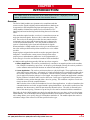
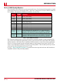
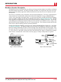
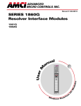
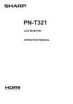
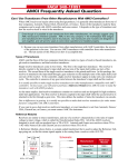
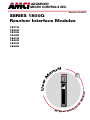
ADVANCED
MICRO CONTROL S INC.
Manual #: 940-08022
SERIES 1800Q
Resolver Interface Modules
al
u
an
140
1831Q
RESO LVE R INTE RFACE
R
T1 E1
F
ADVANCED
MICRO
CONTROLS
O
M
od
ul e s
Resolver
Interface
Module
I/
User
M
1831Q
1832Q
1833Q
1834Q
1841Q
1842Q
1843Q
1844Q
Mo
dico n Q u
t
an
um
GENERAL INFORMATION
Important User Information
The products and application data described in this manual are useful in a wide variety of different applications. Therefore, the user and others responsible for applying these products described herein are responsible
for determining the acceptability for each application. While efforts have been made to provide accurate
information within this manual, AMCI assumes no responsibility for the application or the completeness of
the information contained herein.
UNDER NO CIRCUMSTANCES WILL ADVANCED MICRO CONTROLS, INC. BE RESPONSIBLE OR
LIABLE FOR ANY DAMAGES OR LOSSES, INCLUDING INDIRECT OR CONSEQUENTIAL DAMAGES OR LOSSES, ARISING FROM THE USE OF ANY INFORMATION CONTAINED WITHIN THIS
MANUAL, OR THE USE OF ANY PRODUCTS OR SERVICES REFERENCED HEREIN.
Throughout this manual the following two notices are used to highlight important points.
WARNINGS tell you when people may be hurt or equipment may be damaged if the
procedure is not followed properly.
CAUTIONS tell you when equipment may be damaged if the procedure is not followed properly.
No patent liability is assumed by AMCI, with respect to use of information, circuits, equipment, or software
described in this manual.
The information contained within this manual is subject to change without notice.
Standard Warranty
ADVANCED MICRO CONTROLS, INC. warrants that all equipment manufactured by it will be free from
defects, under normal use, in materials and workmanship for a period of [1] year. Within this warranty
period, AMCI shall, at its option, repair or replace, free of charge, any equipment covered by this warranty
which is returned, shipping charges prepaid, within one year from date of invoice, and which upon examination proves to be defective in material or workmanship and not caused by accident, misuse, neglect, alteration,
improper installation or improper testing.
The provisions of the "STANDARD WARRANTY" are the sole obligations of AMCI and excludes all other
warranties expressed or implied. In no event shall AMCI be liable for incidental or consequential damages or
for delay in performance of this warranty.
Returns Policy
All equipment being returned to AMCI for repair or replacement, regardless of warranty status, must have a
Return Merchandise Authorization number issued by AMCI. Call (860) 585-1254 with the model number
and serial number (if applicable) along with a description of the problem. A "RMA" number will be issued.
Equipment must be shipped to AMCI with transportation charges prepaid. Title and risk of loss or damage
remains with the customer until shipment is received by AMCI.
24 Hour Technical Support Number
24 Hour technical support is available on this product. For technical support, call (860) 583-7271. Your call
will be answered by the factory during regular business hours, Monday through Friday, 8AM - 5PM EST.
During non-business hours an automated system will ask you to enter the telephone number you can be
reached at. Please remember to include your area code. The system will page one of two engineers on call.
Please have your product model number and a description of the problem ready before you call.
ADVANCED MICRO CONTROLS INC.
TABLE OF CONTENTS
General Information
Important User Information .....................
Standard Warranty ...................................
Returns Policy ..........................................
24 Hour Technical Support Number ........
Chapter 2: Installation (continued)
IFC
IFC
IFC
IFC
About This Manual
Introduction .............................................. 3
Navigating this Manual ............................ 3
Revision Record ....................................... 3
Past Revisions ................................ 3
Chapter 1: Introduction
Overview ..................................................
Series 1800Q Family Members ...............
Brushless Resolver Description ...............
AMCI Compatible Transducers ...............
Transducer Specifications ........................
Other Compatible Transducers ................
Programmable Parameters .......................
Transducer Fault Latch .................. 11
Resolver Type ................................ 11
Count Direction ............................. 11
Tachometer Response .................... 11
Scale Factor ................................... 12
Linear Offset .................................. 12
Preset Value ................................... 12
5
6
7
8
9
10
11
Chapter 2: Installation
Power Requirements ................................
Installing the Module ...............................
Status LED Patterns .................................
Transducer Input Connector ....................
Transducer Connector Pin Designations ..
Transducer Cable Installation ..................
13
13
14
14
15
15
Transducer Cable Wiring Diagrams ......... 16
C1T-(x) Wiring Diagram ............. 16
C2T-(x) Wiring Diagram .............. 16
C3T-(x) Wiring Diagram ............. 17
C4T-(x) Wiring Diagram ............. 18
IMT Transducer Interface Module ...........
AMCI Transducer Mounting ....................
AMCI Transducer Outline Drawings .......
Autotech Transducer Installation .............
19
20
20
20
Chapter 3: Module Setup &
Operation
Installing the Concept Software Driver .... 21
Getting the Driver Files ................ 21
Configuring Your Concept
Software ...................................... 21
Adding AMCI Modules to the
Modsoft Module List ............................. 22
Module Definitions ....................... 22
Data Addressing .......................................
Programming Cycle .................................
EEPROM Life Cycle ................................
Output Registers Format ..........................
Command Word ............................ 24
Command Word Bit Values .......... 24
Configuration Word ...................... 25
Configuration Word Bit Values .... 25
Ranges and Factory Defaults ........ 26
23
23
23
24
Input Registers Format ............................. 27
Status Word Format ...................... 28
Status Word Error Bits .................. 28
Status Word Module Status Bits ... 29
Status Word Acknowledge Bit
(Word 1 only) ............................. 29
Sample Program ....................................... 30
20 Gear Drive, Plymouth Ind. Park, Terryville, CT 06786
Tel: (860) 585-1254 Fax: (860) 584-1973 http://www.amci.com
1
TABLE OF CONTENTS
Notes
2
ADVANCED MICRO CONTROLS INC.
ABOUT THIS MANUAL
Introduction
This manual explains the operation, installation, programming, and servicing of eight Series 1800Q Intelligent Resolver Interface Modules for the Modicon® Quantum™ programmable controller systems. These
modules are the 1831Q, 1832Q, 1833Q, 1834Q, 1841Q, 1842Q, 1843Q, and 1844Q. The other two modules
in this series, the 1861Q and 1862Q are covered by the following manual.
h 1861Q and 1862Q Intelligent Resolver Interface Modules.
Written for the engineer responsible for incorporating a Series 1800Q module into a design as well as the
engineer or technician responsible for its actual installation, this manual contains information on hardware
and software configuration as well as data on compatible transducers and proper installation techniques.
Manuals at AMCI are constantly evolving entities. Your questions and comments on this manual and the
information it contains are both welcomed and necessary if this manual is to be improved. Please direct all
comments to: Technical Documentation, AMCI, 20 Gear Drive, Terryville CT 06786, or fax us at (860) 5841973. You can also e-mail your questions and comments to [email protected]
The AMCI logo is a trademark, and “AMCI” is a registered trademark of Advanced Micro Controls Inc.
“Quantum” is a trandmark and “Modicon” is a registered trademark of Schneider Automation, Inc. “Acrobat”
is a registered trademark of Adobe Systems Incorporated. “Viton” is a registered trademark of E.I. DuPont.
“Windows” is a trademark of Microsoft Corporation.
All other trademarks contained herein are the property of their respective holders.
Navigating this Manual
The layout of this manual allows it to be used in both printed and on-line formats. Its on-line form is a PDF
document, which requires Adobe Acrobat Reader version 4.0 or a similar reader before you can access it.
Bookmarks of all the chapter names, section headings, and sub-headings were created in the PDF file so that
you can easily find what you are looking for. The bookmarks should appear when you open the file. If they
don’t, press the F5 key on Windows platforms to bring them up.
Throughout this manual you will also find green text that functions as a hyperlink in HTML documents.
Clicking on the text will immediately jump you to the referenced section of the manual. If you are reading a
printed manual, most links have the page numbers included.
The PDF file is password protected to prevent changes to the document. You are allowed to select and copy
sections for use in other documents and, if you own Adobe Acrobat version 4.05 or later, you are allowed to
add notes and annotations.
Revision Record
The following is the revision history for this manual. In addition to the information listed here, revisions will
fix any known typographical errors and clarification notes may be added.
This manual, 940-08021, is the third release of the manual. It was released on April 10, 2001. It adds information on downloading our Concept driver file from our website, www.amci.com.
Past Revisions
940-08021: Added Modsoft software configuration instructions
940-08020: Initial release of the manual
20 Gear Drive, Plymouth Ind. Park, Terryville, CT 06786
Tel: (860) 585-1254 Fax: (860) 584-1973 http://www.amci.com
3
ABOUT THIS MANUAL
Notes
4
ADVANCED MICRO CONTROLS INC.
CHAPTER 1
INTRODUCTION
This chapter serves as an introduction to the 1800Q series modules. It highlights potential applications, compatible transducers, and all of the modules’ features.
Overview
The Series 1800Q modules are Quantum series compliant cards that
convert resolver signals to digital position and tachometer data that can
be reported over the backplane using input and output registers. The
1800Q modules eliminate the separate resolver decoder box, PLC
input card, and associated wiring needed to bring the resolver data into
a PLC.
Like an absolute optical encoder, a resolver is a sensor that converts an
angle into electrical signals. However, this is where the similarities
end. The resolver is an analog device that does not contain sensitive
components such as optics and electronics that may be damaged by
severe environmental conditions. Also, the position resolution of a
resolver is limited only by the electronics that decode its signals.
When attached to a 1800Q module, the resolver gives an absolute position value with up to thirteen bit position resolution over a six conductor cable.
140
1831Q
RESOLVER INTERFACE
R
T1 E1
F
ADVANCED
MICRO
CONTROLS
Resolver
Interface
Module
Output registers assigned to the module are used to program it from the
backplane. Count direction, counts per turn, linear position offset,
position preset, and tachometer update time are all programmable, as
well as the type of resolver used and how transducer faults are handled.
A 1800Q module application generally falls into one of two categories.
Figure 1.1 Quantum Module
h Rotary Application - The resolver position directly correlates to an angular position on the machine.
One example is monitoring a press ram. As the press cycles through one turn, the resolver position is
used to monitor and control such functions as material feed and part blow-off.
h Linear Application - The resolver position correlates to a physical length. These applications can be
either single turn or multi-turn. An example of a single turn application is a packaging machine where
the resolver completes one turn for each product. Here the resolver position is used to control when
glue is applied or when the package is cut to length. An example of a multi-turn application is monitoring the position of a load on either a track or ball screw. In this type of application, linear position is
translated to rotary position through either a wheel or gearing. The transducer completes several rotations in order to travel the complete distance.
AMCI also has a line of cable reel transducers for use in linear applications. A cable reel transducer has
a stranded stainless steel cable wrapped around a spring loaded drum. As the cable is pulled out of the
transducer, the drum rotates, which in turn rotates the internal resolver. The cable is retracted by the
force of the drums' spring. Distances of up to forty-five feet can be measured with these transducers.
Physically, the Series 1800Q modules are single slot cards that have one, two, three, or four resolver inputs,
called channels. All of the modules directly support transducers from Autotech Controls. One of the module’s settings allows you to specify the type of transducer attached to it. The module adjusts the resolver’s
exicitation voltage to the correct level for the specified resolver type.
20 Gear Drive, Plymouth Ind. Park, Terryville, CT 06786
Tel: (860) 585-1254 Fax: (860) 584-1973 http://www.amci.com
5
1
INTRODUCTION
Series 1800Q Family Members
The ten modules in the 1800Q series are shown in the table below. The 1861Q and 1862Q modules are multiturn modules that are not covered in this manual. Refer to the 1860Q Resolver Interface Modules manual for
these products. The manual is available on our website, www.amci.com.
Model
Transducer
Resolution
Inputs
1831Q
1832Q
1833Q
1834Q
1841Q
1842Q
1843Q
1844Q
1
2
3
4
1
2
3
4
1861Q
1
1862Q
2
10 bit (1,024 counts)
10 bit (1,024 counts)
10 bit (1,024 counts)
10 bit (1,024 counts)
13 bit (8,192 counts)
13 bit (8,192 counts)
13 bit (8,192 counts)
13 bit (8,192 counts)
12 bit (4,096) per turn, 180 turns max. (737,280 counts max.)
1,000 and 1,800 turn transducers are also available. Using these
transducers will reduce the resolution to 409.6 counts per turn.
12 bit (4,096) per turn, 180 turns max. (737,280 counts max.)
1,000 and 1,800 turn transducers are also available. Using these
transducers will reduce the resolution to 409.6 counts per turn.
Table 1.1 Series 1800Q Family Members
The 1830Q and 1840Q modules covered by this manual are primarily intended for single turn applications.
They can be used in multi-turn applications by placing a gear ratio between the output shaft of the machine
and the transducer. AMCI has a line of transducers with an internal (x):1 ratio for use in these applications.
However, you must remember that the maximum number of counts remains fixed at either 1,024 or 8,192
counts. If you need higher resolution, you must use an 1860Q module. These modules provide up to 4,096
counts per turn with a maximum total count of 737,280.
See pg. 8, AMCI Compatible Transducers for information on the single and multi-turn AMCI transducers
compatible with the 1830Q and 1840Q modules.
6
ADVANCED MICRO CONTROLS INC.
1
INTRODUCTION
Brushless Resolver Description
The brushless resolver is unsurpassed by any other type of rotary position transducer in its ability to withstand
the harsh industrial environment. An analog sensor that is absolute over a single turn, the resolver was originally developed for military applications and has benefited from more than 50 years of continuous use and
development.
The resolver is essentially a rotary transformer with one important distinction. The energy coupled through a
rotary transformer is not affected by shaft position whereas the magnitude of energy coupled through a
resolver varies sinusoidally as the shaft rotates. A resolver has one primary winding, the Reference Winding,
and two secondary windings, the SIN and COS Windings (See figure 1.2, Resolver Internal View). The Reference Winding is located in the rotor of the resolver, the SIN and COS Windings in the stator. The SIN and
COS Windings are mechanically displaced 90 degrees from each other. In a brushless resolver, energy is supplied from the Reference Winding to the rotor by a rotary transformer. This eliminates brushes and slip rings
in the resolver and the reliability problems associated with them.
In general, the Reference Winding is excited by an AC voltage called the Reference Voltage (Vr). (See Figure
1.3, Resolver Schematic). The induced voltages in the SIN and COS Windings are equal to the value of the
Reference Voltage multiplied by the SIN or COS of the angle of the input shaft from a fixed zero point. Thus,
the resolver provides two voltages whose ratio represents the absolute position of the input shaft (SIN θ / COS
θ = TAN θ, where θ = shaft angle). Because the ratio of the SIN and COS voltages is considered, any changes
in the resolvers’ characteristics, such as those caused by aging or a change in temperature are ignored.
Rotary
Transformer
S4
Reference Winding
COS
Winding
Vc = Vr COS( θ )
S2
R1
SIN
Winding
Vr
R2
SIN and COS Windings
Figure 1.2 Resolver Internal View
20 Gear Drive, Plymouth Ind. Park, Terryville, CT 06786
Tel: (860) 585-1254 Fax: (860) 584-1973 http://www.amci.com
S3
Rotary
Transformer
θ
Vs = Vr SIN( θ )
S1
Figure 1.3 Resolver Schematic
7
1
INTRODUCTION
AMCI Compatible Transducers
Table 1.2 lists the AMCI single-turn transducers that are compatible with the Series 1830Q and 1840Q modules.
Model
Shaft
Mount
Turns Comments
R11X-J10/7
R11X-J12/7
HT-6
HT-20
HT-20S
0.120"
0.188"
0.188"
0.625"
0.625"
Servo
Servo
Front/Side
Front/Side
Front/Side
1
1
1
1
1
HT-20C
0.625"
Front/Side
1
HT-20K
0.625"
Front/Side
1
HT-20KS
0.625"
Front/Side
1
HT-20L
0.625"
Front/Side
1
HT-20LS
H25-FE
0.625"
0.375"
Front/Side
Flange
1
1
H25-F1E
0.375"
Flange
1
H25-FS
H25-FL
H25-SE
H25-SS
H25-SL
0.375"
Flange
0.375"
Flange
0.375" Servo/Front
0.375" Servo/Front
0.375" Servo/Front
1
1
1
1
1
HT-400
0.625"
Front
1
HT-400-1E
0.625"
Front
1
HT-20-(x)
0.625"
Front
(x)†
HTT-20-1
0.625"
Front
1‡
HTT-400-1
0.625"
Front
1‡
NEMA 1, size 11 resolver. Leads only, no connector.
NEMA 1, size 11 resolver. Leads only, no connector.
NEMA 13 R11X-J12/7 transducer
NEMA 4 heavy duty transducer
HT-20 with side connector
NEMA 4X stainless steel HT-20 w/ Viton® shaft
seal, and 0.5" NPT thread for conduit connection.
Internal terminal plug for resolver connections.
NEMA 4X hard coat anodized HT-20, stainless steel
shaft w/ Viton shaft seal.
HT-20K with side connector.
NEMA 4X hard coat anodized HT-20, stainless steel
shaft w/ Nitrile shaft seal.
HT-20L with side connector.
NEMA 4, size 25, end connector
NEMA 4, size 25, end connector. Bolt-in replacement for Namco/C&A HT-11B transducers.
NEMA 4, size 25, side connector
NEMA 4, size 25, integral 15 foot (3 meter) cable
NEMA 4, size 25, end connector
NEMA 4, size 25, side connector
NEMA 4, size 25, integral 15 foot (3 meter) cable
NEMA 4, Bolt-in replacement for Autotech RL100
transducers. Also has HT-20 bolt pattern. 1" NPT
thread for conduit connection. Internal terminal strip
for resolver connections.
Same as HT-400 with an AMCI MS connector
instead of a conduit connection.
HT-20 with internal (x):1 gear ratio
Redundant single turn resolvers, single MS connector
Redundant single turn resolvers. Bolt-in replacement for Autotech RL220 transducers. Dual AMCI
MS connectors.
† Available gear ratios are: 2:1, 2.5:1, 2.77:1, 3:1, 4:1, 4.8:1, 5:1, 6:1, 7:1, 8:1, 9:1, 10:1, 12:1, 13:1, 15:1, 16:1,
18:1, 20:1, 24:1, 36:1, 40:1, 50:1, 60:1, 64:1, 100:1, 105:1, 150:1, 180:1, 250:1 and 256:1. Additional gear
ratios may be available. Check our website, www.amci.com, for an up-to-date listing.
‡ This package contain two resolvers geared 1:1 with the input shaft. Most commonly used in systems that mandate redundant sensors, AMCI can install two different size 11 resolvers in the package per customer requirements. Contact AMCI for more information.
Table 1.2 Compatible AMCI Transducers
8
ADVANCED MICRO CONTROLS INC.
1
INTRODUCTION
Transducer Specifications
The following table contains the mechanical and environmental specifications for all AMCI single-turn transducers that are compatible with the Series 1830Q and 1840Q modules.
Specification
All HT-20-(x),
HT-400, HTT-20-1,
& HTT-400-1
All HT-20’s
Shaft Diameter
0.625"
Radial Shaft Loading 400 lbs. max.
Axial Shaft Loading 200 lbs. max.
Starting Torque 8oz-in@25°C
Moment of Inertia
6.25X10⁻⁴
(oz-in-sec2)
Weight
4 lbs.
Enclosure NEMA 4 or 4X
0.625"
400 lbs. max.
200 lbs. max.
8oz-in@25°C
All H25’s
HT-6
All R11’s
0.375"
0.188"
0.120" or 0.188"
40 lbs. max.
8 lbs. max.
2 lbs. max.
20 lbs. max.
4 lbs. max.
1 lb. max.
1.5oz-in@25°C 0.5oz-in@25°C 0.1oz-in@25°C
8.75X10⁻⁴
6.00X10⁻⁴
2.10X10⁻⁴
0.51X10⁻⁴
4 lbs.
NEMA 4
1 lb.
NEMA 4
0.7 lb.
NEMA 13
0.25 lb.
NEMA 1
Environmental (All Transducers)
Operating Temp
-20 to 125°C
Shock
50 G’s for 11 milliseconds
Vibration
5 to 2000 Hz @ 20 G’s
Table 1.3 Single-Turn Transducer Specifications
20 Gear Drive, Plymouth Ind. Park, Terryville, CT 06786
Tel: (860) 585-1254 Fax: (860) 584-1973 http://www.amci.com
9
1
INTRODUCTION
Other Compatible Transducers
In addition to AMCI transducers, the Series 1830Q and 1840Q modules directly supports transducers from
Autotech Controls. The supported Autotech models are:
h
h
h
h
All SAC-RL100 Transducers (Size 40, NEMA 13)
All E6R and E7R-RL101 Transducers. (Size 25, NEMA 13)
SAC-RL101-010 Resolvers. (Size 11, NEMA 1)
All SAC-RL220 Transducers (Size 40, NEMA 13, Redundant resolvers)
If your project is a new installation, or you can budget the cost of replacing the transducer, we strongly suggest using AMCI transducers. AMCI is the only company in the marketplace that designs and manufactures
the resolvers used in its products. Our transducers and electronics are designed to work together, and will
work for years to come when specified and installed properly.
If your project involves converting system originally designed for Autotech products, you will likely be able
to use AMCI transducers without re-designing transducer mounting brackets. Table 1.4 lists Autotech transducer part numbers and the AMCI bolt-in replacements. Note that the resolvers used in AMCI transducers
are for AMCI products, and all connectors are AMCI standard connectors, unless otherwise stated.
Autotech
Transducers
AMCI
Transducers
SAC-RL101-010
Comments
identical except that wires come
R11X-J10/7 Mechanically
out the back instead of the side.
E6R-RL101-000EF
E7R-RL101-000EF
E6R-RL101-000ES
E7R-RL101-000ES
E6R-RL101-000SF
E7R-RL101-000SF
H25-FE
Bolt-in replacement. Shorter body length.
H25-SE
E6R-RL101-000SS
E7R-RL101-000SS
H25-SS
SAC-RL100-010
SAC-RL100-M11
SAC-RL220-G010C,
SAC-RL220-G010M
HT-400
HT-400-1E
Bolt-in replacement when servo mounting.
Different bolt pattern on front, shorter body.
Bolt-in replacement. Shorter body length, side
connector in different location.
Bolt-in replacement when servo mounting.
Different bolt pattern on front, shorter body
length, side connector in different location.
Direct replacement.
Bolt-in replacement, AMCI connector.
HTT-400-1
Bolt-in replacement, dual AMCI connectors
with similar configuration to “-G101M”
H25-FS
Table 1.4 Autotech / AMCI Transducer Cross Reference
If you decide to use your Autotech transducers, you must change the Resolver Type parameter. If you set the
Resolver Type to Autotech, then all of the transducers must be Autotech's. If you wish to bring both AMCI
and Autotech single-turn transducers into one unit, you must set the Resolver Type parameter to AMCI and
use an AMCI RM-3 Reference Module to connect the Autotech transducers.
1) Due to differences in cable construction, AMCI does not support installations that use transducer cables supplied by Autotech Controls. When using Autotech transducers, you must
use Belden 9873, or Belden 9730 if your cable length is over one hundred feet.
2) For more information on interfacing with Autotech transducer, see AMCI’s FAQ, “Using
Transducers From Other Manufacturers”, posted on our website, www.amci.com.
10
ADVANCED MICRO CONTROLS INC.
INTRODUCTION
1
The remainder of this chapter introduces the many programmable features of the 1800Q series
module. It also introduces backplane programming concepts that allows you to control the module
from the processor.
Programmable Parameters
An 1800Q module is configured by setting its programmable parameters. These parameters are stored in the
modules nonvolatile memory, so there is no need to configure the module after every power up.
The nonvolatile memory is an EEPROM that is rated for approximately 100,000 write cycles.
Therefore, continuously presetting the position or writing new parameters to the module
should be avoided. If your application requires continuous presetting of the position, consider
using your ladder logic program to calculate the offset.
Transducer Fault Latch
The modules can detect a fault with the transducer that would prevent the module from calculating the correct
position value. This includes transient faults such as electrical noise in the resolvers signal from an outside
source. The Transducer Fault Latch parameter gives you ability to latch the transient fault when it occurs or
have the module clear the transient fault as soon as possible. If you decide to latch transducer faults, you must
send a command to the module to clear the fault.
h The Transducer Fault Latch default value is on. This latches a transducer fault when it occurs.
The Transducer Fault Latch is enabled by default because the module can detect and clear transducer faults
much faster than the processor scans the module. Therefore, latching the transducer fault guarantees that the
processor will see a fault if it occurs. In addition to status bits in the input registers, the status indicators on
the front panel show when a transducer fault has occurred, and whether or not it can be cleared.
Resolver Type
The Resolver Type parameter makes most Autotech transducers compatible with the 1800Q modules.
h The Resolver Type default value is AMCI.
h If you are using only Autotech transducers, set the parameter to Autotech.
If you plan to use both AMCI and Autotech resolvers with a single module you must set the
Resolver Type to AMCI. You will need an AMCI RM-3 Reference Module to interface the
Autotech transducers with the card. See AMCI’s FAQ, “Using Transducers From Other Manufacturers”, posted on our website, www.amci.com for more information.
Count Direction
This parameter sets the direction of transducer shaft rotation to increase the position count. If the transducer
cable is wired as specified in this manual and the count direction is set to positive, the position count will
increase with clockwise rotation (looking at the shaft). If the count direction is set to negative, the position
count will increase with counter-clockwise rotation.
h The Count Direction default value is positive.
Tachometer Response
This parameter sets the time between tachometer updates. The tachometer has a resolution of 1.0 RPM and a
maximum value of 5,000 RPM.
h The default value is 120 milliseconds between updates.
The parameter can be set to 120 or 24 milliseconds. The 24 millisecond setting offers quicker response to
changes in transducer speed while the 120 millisecond setting offers better speed averaging.
20 Gear Drive, Plymouth Ind. Park, Terryville, CT 06786
Tel: (860) 585-1254 Fax: (860) 584-1973 http://www.amci.com
11
1
INTRODUCTION
Programmable Parameters (continued)
Scale Factor
The Scale Factor sets the number of counts per turn of the resolver.
h The Scale Factor default is 360. This gives 1 degree resolution.
h 1830Q modules can program the Scale Factor to any value between 2 and 1024.
h 1840Q modules can program the Scale Factor to any value between 2 and 8192.
Linear Offset
The Linear Offset changes the range of position counts by adding a fixed number to it. The use of the Linear
Offset is best illustrated with the following example.
7.5m
An 1841Q is used to measure a 5.000 meter span with one millimeter resolution. Therefore, the total number of counts over the full travel is:
5.0 meters * 1000 mm/meter = 5000 counts.
5.0m
Span
2.5m
Linear
Offset
The Scale Factor parameter is then set to this value. The 5.000 meters that the transducer measures is in the range of 2.500 to 7.500 meters on the machine. You can use the
Linear Offset to force the module to send the position data to the processor in the correct format instead of using the processor to add an offset once the position value is in
the data table. The formula for the Linear Offset is:
Minimum Desired Value
2.500 meters
*
Resolution
=
* 1000 mm/meter =
Linear Offset
2500 counts
h The Linear Offset default value is zero.
h The Linear Offset can be programmed from zero to: (65,536 - (Scale Factor)).
0m
Figure 1.4
Linear Offset
Example
Preset Value
The Preset Value parameter allows you to set the value of the position count without calculating the required
offset. Programming the Preset Value does not change the position data, it only sets the value the position
will change to when a Preset Command is initiated.
h The Preset Value defaults to zero.
h The Preset Value can be programmed from Linear Offset value to:
(Linear Offset + (Scale Factor-1)).
12
ADVANCED MICRO CONTROLS INC.
CHAPTER 2
INSTALLATION
This chapter gives information on installing the module and transducers. This includes information on module power requirements, transducer mounting, shaft loading, and cable installation.
Power Requirements
A Series 1800Q module draws power from the I/O backplane +5Vdc supply. The maximum current draw is
dependent on the number of transducer channels and is given in the table below. Add this to the power
requirements of all other modules in the backplane when sizing the system power supply.
Maximum Current Draw
Maximum Power Draw
1831Q/1841Q
1832Q/1842Q
1833Q/1843Q
1834Q/1844Q
385 mA
1.93 W
415 mA
2.08 W
445 mA
2.23 W
475 mA
2.38 W
Table 2.1 Backplane Power Draw
Installing the Module
Like all Quantum I/O modules, the 1800Q modules can be removed and installed under power (hot swapped)
without damaging the module or backplane. The module can be installed in a local or remote I/O rack.
Unplug the Transducer Input Connector before hot swapping the module.
The 1800Q’s install into the backplane like all other Quantum modules.
1) At an angle to the backplane, align the two mounting pins on the top of the module’s case with the two
hooks at the top of the backplane.
2) Gently rotate the module down until it makes electrical connection with the backplane’s I/O bus
connector.
3) Tighten the mounting screw at the bottom of the module’s case to fasten it to the backplane. Use
care when starting this screw so that you do not strip the backplane’s threads. The maximum
tightening torque for this screw is 4 in-lbs (0.45 Nm)
The mounting screw must be tightened for proper operation. If this screw
is not tightened, the module will not have a solid connection to chassis
ground and this could affect module operation.
20 Gear Drive, Plymouth Ind. Park, Terryville, CT 06786
Tel: (860) 585-1254 Fax: (860) 584-1973 http://www.amci.com
13
2
INSTALLATION
Status LED Patterns
Depending on the model number that you are using, the module’s front panel has from five to eleven status
LED’s. Figure 2.1 shows the position of the LED’s and their meaning.
RUN – On when the module is operating
without a fault.
140
1844Q
RESOLVER INTERFACE
R
T1
T2
T3
T4
Active
E1
E2
E3
E4
F
Active – On when the module is communicating with the processor.
FAULT – On when one of the following
module error has occured.
h EEPROM Error
h Reference Error
TRANSDUCER FAULT –
When one of these red LED's are on,
there is a problem with the transducer
connection. The numbers designate
which channel is faulted. If the red
LED is on instead of alternate flashing
with the green LED, then the fault
cannot be cleared until the wiring or
transducer problem is fixed.
TRANSDUCER OK –
When these green LED's are on, the
transducer connection to the module
is OK. The numbers designate the
transudcer channel.
ALTERNATE FLASHING –
When the Transduce Fault Latch is
enabled and a transient condition
faults the transducer connection, the
green and red transducer LED's will
alternately flash to signify that the
latched transducer fault is clearable.
Figure 2.1 Status LED Patterns
Transducer Input Connector
The transducer input connector of an 1831Q, 1832Q, 1841Q, or 1842Q module has eight contacts while the
connector of an 1833Q, 1834Q, 1843Q, or 1844Q module has fourteen contacts. The following table lists the
AMCI and Phoenix Contact part numbers on the mating connectors:
AMCI Part #
Phoenix Part #
8 Pin Connector
14 Pin Connector
MS-8
MSTB2.5/8-ST-5.08
1757077
MS-14
MSTB2.5/14-ST-5.08
1757132
Table 2.2 Transducer Input Connector
14
ADVANCED MICRO CONTROLS INC.
2
INSTALLATION
Transducer Input Connector (continued)
Figure 2.2 shows the pin out to industry standard resolver wire designations. Note that the connector for three
and four channel modules is shown. The connector for the 1831/32/41/42Q modules has only eight pins and
its connections coresponds to pins 1 through 8 in the figure.
14
13
12
11
10
9
8
7
6
5
4
3
2
1
S3, CH4
S4, CH4
S3, CH3
S4, CH3
S1 & S2, CH3 & CH4
CH3 & CH4 Shields
S3, CH2
S4, CH2
S3, CH1
S4, CH1
S1 & S2, CH1 & CH2
CH1 & CH2 Shields
R2, All Channels
R1, All Channels
h CH – Channel Number
h R1/R2 – Reference Winding
h S1/S3 – COS Winding
h S2/S4 – SIN Winding
Figure 2.2 Transducer Input Connector
Transducer Connector Pin Designations
Figure 2.3 shows the connector pin outs for AMCI single turn transducers. Note that some AMCI transducers have integral cables or conduit
connections. For a complete listing of AMCI transducers without connectors, refer to AMCI Compatible Transducers, starting on page 8.
S1: (RED)
S3: (BLK)
R1: (RED/WHT)
R2: (BLK/WHT)
S2: (YEL)
S4: (BLU)
Figure 2.3 Transducer Connector Pin Designations
Transducer Cable Installation
Use the table below to determine the correct cable and connectors for your application. Cables that have been
assembled and tested are available from AMCI under the given part numbers. If you are making your own
cables, cable and connectors can be ordered from AMCI.
Belden Cable Number
Module
AMCI Part #
(x) = feet
100 ft–
100 ft+
Module
Connector
Transducer
Connector
1831Q/41Q
1832Q/42Q
1833Q/43Q
1834Q/44Q
C1T-(x)
C2T-(x)
C3T-(x)
C4T-(x)
9873
9873
9873
9873
9730
9730
9730
9730
MS-8
MS-8
MS-14
MS-14
MS-16 (qty 1)
MS-16 (qty 2)
MS-16 (qty 3)
MS-16 (qty 4)
Table 2.3 Transducer Cable Numbers
1) Resolvers are low voltage devices. The cable can be installed in conduit along with other
low power cabling such as communication cables and low power ac/dc I/O lines. It cannot
be installed in conduit with ac power lines or high power ac/dc I/O lines.
2) The shields of the transducer cable must be grounded at the module only! When installing
the cable, treat the shield as a signal conductor. Do not connect the shield to ground at any
junction box or the transducer. These precautions will minimize the possibility of ground
loops that could damage the module or PLC.
20 Gear Drive, Plymouth Ind. Park, Terryville, CT 06786
Tel: (860) 585-1254 Fax: (860) 584-1973 http://www.amci.com
15
2
INSTALLATION
Transducer Cable Wiring Diagrams
C1T-(x) Wiring Diagram (1831Q / 1841Q)
BLK
WHT
8
7
6
5
4
3
2
1
GRN
S3
S4
S1, S2
Shields
R2
R1
E
D
BLK
F
G
SHIELDS
RED
BLK
A
C
B
Transducer
Connector
Module Connector
AMCI Part #: MS-16
Bendix #:
MS3106A16S-1S
BELDEN 9873 Cable
AMCI Part #: MS-8
Phoenix #: MSTB2.5/8-ST-5.08
17 57 07 7
For cable lengths greater than
100' (30 meters) use BELDEN 9730.
Figure 2.4 C1T-(x) Wiring Diagram
C2T-(x) Wiring Diagram (1832Q / 1842Q
BLK
WHT
E
BLK
GRN
F
BLK
RED
D
G
A
C
B
Transducer 2
Connector
BELDEN 9873 Cable (Two places)
For cable lengths greater than 100' (30 meters) use BELDEN 9730.
BLK
8
7
6
5
4
3
2
1
S3
S4
S3
S4
S1, S2
Shields
R2
R1
AMCI Part #: MS-16
Bendix #:
MS3106A16S-1S
WHT
BLK
E
D
GRN
F
SHIELDS
G
A
RED
BLK
C
B
Transducer 1
Connector
AMCI Part #: MS-16
Bendix #:
MS3106A16S-1S
Module Connector
AMCI Part #: MS-8
Phoenix #: MSTB2.5/8-ST-5.08
17 57 07 7
Figure 2.5 C2T-(x) Wiring Diagram
16
ADVANCED MICRO CONTROLS INC.
20 Gear Drive, Plymouth Ind. Park, Terryville, CT 06786
Tel: (860) 585-1254 Fax: (860) 584-1973 http://www.amci.com
1
2
3
4
5
6
8
7
9
10
11
12
13
14
AMCI Part #: MS-14
Phoenix #: MSTB 2.5/14-ST-5.08
17 57 13 2
Module Connector
S3
S4
S1, S2
Shields
S3
S4
S3
S4
S1, S2
Shields
R2
R1
SHIELDS
RED
BLK
BLK
GRN
BLK
WHT
BLK
RED
BLK
GRN
BLK
WHT
BLK
GRN
SHIELDS
BLK
RED
BLK
WHT
A
G
B
D
C
F
F
A
E
A
E
G
G
B
D
B
D
C
C
AMCI Part #: MS-16
Bendix #:
MS3106A16S-1S
Transducer 1
Connector
AMCI Part #: MS-16
Bendix #:
MS3106A16S-1S
Transducer 2
Connector
For cable lengths greater than 100' (30 meters) use BELDEN 9730.
BELDEN 9873 Cable (Three places)
F
E
AMCI Part #: MS-16
Bendix #:
MS3106A16S-1S
Transducer 3
Connector
INSTALLATION
2
Transducer Cable Wiring Diagrams (continued)
C3T-(x) Wiring Diagram (1833Q / 1843Q)
Figure 2.6 C3T-(x) Wiring Diagram
17
18
14
13
12
11
10
9
8
7
6
5
4
3
2
1
AMCI Part #: MS-14
Phoenix #: MSTB 2.5/14-ST-5.08
17 57 13 2
Module Connector
S3
S4
S3
S4
S1, S2
Shields
S3
S4
S3
S4
S1, S2
Shields
R2
R1
SHIELDS
RED
BLK
BLK
GRN
BLK
WHT
BLK
RED
BLK
GRN
BLK
WHT
BLK
GRN
SHIELDS
BLK
RED
BLK
WHT
BLK
RED
BLK
GRN
BLK
WHT
A
E
A
E
A
G
G
G
B
D
B
D
B
D
C
C
C
AMCI Part #: MS-16
Bendix #:
MS3106A16S-1S
Transducer 2
Connector
AMCI Part #: MS-16
Bendix #:
MS3106A16S-1S
Transducer 3
Connector
F
A
E
G
B
D
C
AMCI Part #: MS-16
Bendix #:
MS3106A16S-1S
Transducer 1
Connector
For cable lengths greater than 100' (30 meters) use BELDEN 9730.
BELDEN 9873 Cable (Four places)
F
F
F
E
AMCI Part #: MS-16
Bendix #:
MS3106A16S-1S
Transducer 4
Connector
2
INSTALLATION
Transducer Cable Wiring Diagrams (continued)
C4T-(x) Wiring Diagram (1834Q / 1844Q)
Figure 2.7 C4T-(x) Wiring Diagram
ADVANCED MICRO CONTROLS INC.
2
INSTALLATION
IMT Transducer Interface Module
The IMT is an interface module that simplifies field wiring to an 1833Q, 1834Q, 1843Q or 1844Q. This module has terminal blocks that connect four C1T transducer cables to a single eight foot cable. This cable connects the IMT to the module. Figure 2.8 is an outline drawing of the IMT and cable. The C1T-(x) Wiring
Diagram is on page 16.
1 2 3 4 5 6 7 8 9 10 11 12 13 14
GRN
BLK
WHT
BLK
BLU
SHIELDS
YEL
BLK
BRN
BLK
BLK
SHIELDS
RED
BLK
Module Connector
AMCI Part #: MS-14
Phoenix Part #:
MSTB2.5/14-ST-5.08
17 57 13 2
(Four places)
C4IMT Cable
Pre-assemblied 8 ft. cable
with connectors. The cable
is included with the IMT
module. Ends of the cable
are interchangable.
BELDEN 9731
1 2 3 4 5 6 7 8 9 10 11 12 13 14
3.00"
(76.2)
2.500"
(63.50)
IMT INTERFACE MODULE
TRANSDUCER 2
TRANSDUCER 4
TRANSDUCER 1
TRANSDUCER 3
0.17" (4.3) Dia. Thruhole (Four places)
0.25" (6.4)
4.500"
0.25" (6.4)
(114.30)
5.00"
(127.0)
1.80" (45.7) max. with mating connectors installed.
(Transducer 4 connector shown.)
Additional 1" (25) clearance recommended
for mating connector removal.
1.40" max.
(35.6)
0.44" (11.2)
Figure 2.8 IMT Outline Drawing
20 Gear Drive, Plymouth Ind. Park, Terryville, CT 06786
Tel: (860) 585-1254 Fax: (860) 584-1973 http://www.amci.com
19
2
INSTALLATION
AMCI Transducer Mounting
All AMCI resolver based transducers are designed to operate in the industrial environment and therefore
require little attention. However, there are some general guidelines that should be observed to ensure long
life.
h Limit transducer shaft loading to the following maximums:
Radial Load
Axial Load
All 0.625" Shafts
100 lbs. (445 N)
50 lbs. (222 N)
All 0.375" Shafts
30 lbs. (133 N)
15 lbs. (66.7 N)
All Other Shafts
1 lb. (4.45 N)
0.5 lb. (2.22 N)
Table 2.4 Transducer Bearing Loads
h Minimize shaft misalignment when direct coupling shafts. Even small misalignments produce large
loading effects on front bearings. It is recommended that you use a flexible coupler whenever possible.
A flexible coupler is required for all HT-6 transducers and R11 resolvers.
AMCI Transducer Outline Drawings
AMCI offers a broad line of resolver based transducers for use with the Series 1800Q modules. (See AMCI
Compatible Transducers starting on page 8.) Outline drawings for all of these transducers, and full spec
sheets for our most popular transducers, are available on our website, www.amci.com. If you do not have
internet access, contact AMCI and we will fax the information to you.
Autotech Transducer Installation
The manual is intended to be distributed on-line in PDF format, so file size is always a concern. If you
require information on installing Autotech transducers, or using AMCI and Autotech transducers together,
download the FAQ, “Using Transducers From Other Manufacturers”, posted on our website.
Even though Autotech transducers are usable, we strongly recommend using AMCI transducers whenever
possible. Refer to the Autotech / AMCI Transducer Cross Reference table on page 10 for information on our
recommended replacements for Autotech transducers. Remember that if you do decide to use Autotech transducers, you cannot use Autotech transducer cable. Due to differences in construction, you must use the cable
types specified by AMCI.
20
ADVANCED MICRO CONTROLS INC.
CHAPTER 3
MODULE SETUP & OPERATION
Installing the Concept Software Driver
Getting the Driver Files
If this is your first time using a Series 1800Q module, then you will probably need to install our driver files
for the Concept software. These files available on our website, www.amci.com. You’ll find them as a single
ZIP file in our Document Retrieval section. Once you’ve downloaded the ZIP file, decompress it to either
your hard drive or a floppy disk.
Configuring Your Concept Software
1) Your Concept software must be version 2.1 or above in order to install the driver for our
Series 1800Q modules.
2) Our driver is for all of our Quantum modules. When you install the driver, you have the
choice of installing all of the modules or only the one that you are presently using. If you
install all of them, then you will not have to install the driver again at a later date.
Use the following procedure to install the driver on a Windows 95, 98 or NT 4.0 system.
Use the following procedure to install the driver on a Windows 95, 98 or NT 4.0 system.
1) If you un-zipped the driver files to a floppy, insert the disk into its drive.
2) Click on the Windows START button.
3) Select Programs p Concept -0VX.x p ModConnect Tool. The Concept Module Installation
screen will appear. ‘X.x’ is the revision number of the software. It must be 2.1 or above in order to
install the supplied driver.
4) Click on File in the menu bar.
5) Click on the Open Installation File choice in the pull down menu. The Open MDC-File screen will
appear.
6) Click on the Drive pull down box and select the location of the AMCI driver files that you un-zipped
after downloading them from www.amci.com.
7) Select the file amcirslv.mdc.
8) Click on the Add All button to add all of our Quantum modules to your list, or select only the module
you wish to install and click the Add Module button.
9) Click the Close button
10)Click on File in the menu bar.
11)Click on the Save Changes choice in the pull down menu.
12)Close the Concept Module Installation.
The help file that is included in the ZIP file with the software drivers does not contain any information at this
time but it must remain on the disk or in the folder with the rest of the files in order for the drivers to install
properly.
20 Gear Drive, Plymouth Ind. Park, Terryville, CT 06786
Tel: (860) 585-1254 Fax: (860) 584-1973 http://www.amci.com
21
3
MODULE SETUP & OPERATION
Adding AMCI Modules to the Modsoft Module List
If you are using Modsoft to configure your system, you must edit one of the Modsoft system text files to add
the AMCI module definitions before you can add one of our modules to your system. Use the following procedure to edit the gcnftcop.sys file used by Modsoft.
1) Before editing gcnftcop.sys, copy this file to a safe location or to a new file name, such as
gcnftcop.old. The file resides in the ‘X’:\Modsoft\Runtime directory where ‘X’ is the drive letter that
Modsoft is installed in. This will give you a backup copy of this file that you can restore if you make an
error editing the gcnftcop.sys file.
2) Using a text editor such as Edit for DOS or Notepad for Windows, open the gcnftcop.sys file in the
‘X’:\Modsoft\Runtime directory. ‘X’ is the drive letter that Modsoft is installed in.
3) Scroll through the file until you find the last Quantum module currently listed.
4) Add the appropriate module definitions from the list below. Note that the List Number field must be
unique for each module and is set to the next available number.
5) Save the changes to “GCNFTCOP.SYS” and exit your text editor.
Any modules added from the list below should now appear in the list of modules available to Modsoft when
the rack is being configured.
Module Definitions
AMCI 1831Q, 240, 0, 6, 10, 1 channel 10 bit, 1, L0143, 2, 0000, 0
AMCI 1832Q, 241, 0, 12, 10, 2 channel 10 bit, 1, L0143, 2, 0000, 0
AMCI 1833Q, 242, 0, 18, 10, 3 channel 10 bit, 1, L0144, 2, 0000, 0
AMCI 1834Q, 243, 0, 24, 10, 4 channel 10 bit, 1, L0144, 2, 0000, 0
AMCI 1841Q, 244, 0, 6, 10, 1 channel 13 bit, 1, L0143, 2, 0000, 0
AMCI 1842Q, 245, 0, 12, 10, 2 channel 10 bit, 1, L0143, 2, 0000, 0
AMCI 1843Q, 246, 0, 18, 10, 3 channel 10 bit, 1, L0144, 2, 0000, 0
AMCI 1844Q, 247, 0, 24, 10, 4 channel 10 bit, 1, L0144, 2, 0000, 0
List Number field. This number must be unique for each
module in the list. Therefore, the number you actually use
may be different than the numbers given here.
22
ADVANCED MICRO CONTROLS INC.
3
MODULE SETUP & OPERATION
Data Addressing
When setting up your rack, you must select the module from the drivers list and the starting address of the
input and output registers used by the module. The actual starting address used is dependent on your setup,
but the input registers start at 30,001 and the output registers start at 40,001.
Table 3.1 shows the number of input and output registers used by the module.
ID Code
1831Q
1832Q
1833Q
1834Q
1841Q
1842Q
1843Q
1844Q
143h
143h
144h
144h
143h
143h
144h
144h
Input Registers Output Registers
3
6
9
12
3
6
9
12
5
5
5
5
5
5
5
5
Table 3.1 ID Code and I/O Registers
Programming Cycle
Changes to an 1800Q’s setup are accomplished through a Programming Cycle. Two bits control the cycle.
The Transmit Bit in the first output register initiates a Programming Cycle and the Acknowledge Bit in the
first input register signals the modules acceptance of the data. A Programming Cycle consists of six steps.
1) Write the new programming data into the output registers with the Transmit Bit reset. This step
insures that the correct data is in the output registers before the Programming Cycle begins.
2) Set the Transmit Bit. A Programming Cycle is initiated when this bit makes a 0p1 transition.
3) Once the unit is done with the programming data, it will set any necessary error bits and the
Acknowledge Bit in its input registers.
4) Once you see the Acknowledge Bit set, check for any errors. The error bits are only valid while the
Acknowledge Bit is set.
5) Respond to any errors and reset the Transmit Bit.
6) The 1800Q responds by resetting the Acknowledge Bit. The Programming Cycle is complete.
Programming Cycles are used to write new programmable parameter values to the module and/or preset the
transducer position. As you will see in the Output Registers Format section on the following page, programming data is written to the module one channel at a time. Note that you can program and preset with one
cycle. Therefore it takes four Programming Cycles to completely setup a 1834/44Q module.
EEPROM Life Cycle
The EEPROM is guaranteed for approximately 100,000 write cycles. Therefore, continuously presetting the
position or writing new parameters to the module should be avoided. If your application requires continuous
presetting of the position, consider using your ladder logic program to calculate the offset.
20 Gear Drive, Plymouth Ind. Park, Terryville, CT 06786
Tel: (860) 585-1254 Fax: (860) 584-1973 http://www.amci.com
23
3
MODULE SETUP & OPERATION
Output Registers Format
The format and order of the Output Registers are shown in table 3.2. Note that only one channel can be programmed at a time and that all data must be present when a Programming Cycle is initiated. All programming data is in decimal format.
Output Registers
Register 1
Register 2
Register 3
Register 4
Register 5
Command Word
Configuration Word
Scale Factor
Linear Offset
Preset Value
Table 3.2 Output Register Format
Command Word
The first output register assigned to the module is the Command Word. It defines what actions will be taken
with the Programming Cycle. Figure 3.1 shows the format of the Command Word. Note that bits 3 through 8
are reserved and must always equal zero.
Output Register 1: Command Word Format
AplyPst1
AplyPst2
AplyPst3
AplyPst4
PGM1
PGM2
PGM3
0 0 0 0 0 0
PGM4
ClrErr
TRMT
01 02 03 04 05 06 07 08 09 10 11 12 13 14 15 16
Figure 3.1 Command Word Format
Command Word Bit Values
TRMT: Transmit Bit, Bit 01. A 0p1 transition on this bit starts a Programming Cycle. The state of the
other bits in the word are ignored until this bit makes the 0p1 transition.
ClrErr: Clear Errors, Bit 02. The module will attempt to clear all pending errors when this bit is set. This
includes all module errors, programming errors, and latched transducer faults.
PGM4: Program Channel 4, Bit 09. If you are not using an 1834Q or 1844Q, this bit must be zero. Setting
this bit will program the parameters of channel 4 to the values specified in the remaining output registers. Note that only one of the four Program Channel bits, (9, 10, 11, or 12), can be set when a Programming Cycle is initiated.
PGM3: Program Channel 3, Bit 10. If you are using an 1832Q, 1842Q, 1831Q, or 1841Q, this bit must be
zero. Setting this bit will program the parameters of channel 3 to the values specified in the remaining output registers. Note that only one of the four Program Channel bits, (9, 10, 11, or 12), can be
set when a Programming Cycle is initiated.
PGM2: Program Channel 2, Bit 11. If you are using an 1831Q, or 1841Q, this bit must be zero. Setting
this bit will program the parameters of channel 2 to the values specified in the remaining output registers. Note that only one of the four Program Channel bits, (9, 10, 11, or 12), can be set when a Programming Cycle is initiated.
PGM1: Program Channel 1, Bit 12. Setting this bit will program the parameters of channel 1 to the values
specified in the remaining output registers. Note that only one of the four Program Channel bits, (9,
10, 11, or 12), can be set when a Programming Cycle is initiated.
24
ADVANCED MICRO CONTROLS INC.
3
MODULE SETUP & OPERATION
Output Registers Format (continued)
Command Word Bit Values (continued)
AplyPst4-1: Apply Preset, Channel 4–1, Bits 13–16. If you set any of these bits, the position value of the
selected channel(s) will be set to its Preset Value if the Programming Cycle completes successfully.
1) If you set an Apply Preset, Channel ‘n’ bit for a channel that does not exist in your module, an
error will be generated by the module. (For example, using an 1831Q and setting the
AplyPst4 bit.)
2) You can program a channel and preset it with a single Programming Cycle. The programming data is accepted first. Therefore, the position will preset to the value specified in the
programming data.
Configuration Word
The second output register assigned to the module is the Configuration Word. It programs the four parameters that can be set with single bits. Note that bits 01 through 12 are reserved and must always equal zero. Bit
13, which programs the Resolver Type parameter, is only available on channel 1. When programming channels 2 through 4, this bit must equal 0.
Output Register 2: Configuration Word Format
Bit must equal zero
for all channels.
TResp
CDir
TFLtch
0 0 0 0 0 0 0 0 0 0 0 0
RType
01 02 03 04 05 06 07 08 09 10 11 12 13 14 15 16
Bit must equal zero
for channels 2 - 4.
Figure 3.2 Configuration Word Format
Configuration Word Bit Values
RType: Resolver Type, Bit 13. Setting this bit configures the module for Autotech transducers. Therefore
this bit should remain reset for normal operation.
h Because the Resolver Type parameter affects all channels, it is programmed when programming chan-
nel one. When programming any other channel, this bit must equal zero.
TFLtch: Transducer Fault Latch, Bit 14. The transducer fault latch is enabled when this bit is reset during a
Programming Cycle. This means that all transient transducer faults will be reported by the module
and must be cleared by the PLC with a Programming Cycle that has the Clear Errors bit set in the
Command Word. When this bit is set, the Transducer Fault Latch will be disabled and all transducer
faults will be cleared by the module as soon as the fault condition is removed.
CDir:
Count Direction, Bit 15. When transducer cables are wired as specified in the manual, the position
value will increase with clockwise rotation of the transducer shaft if this bit is reset during a Programming Cycle. When this bit is set, the position value will increase with counter-clockwise rotation.
TResp: Tachometer Response, Bit 16. Setting this bit will program the tachometer to update every 24 mil-
liseconds. Resetting this bit will program the tachometer to update every 120 milliseconds.
20 Gear Drive, Plymouth Ind. Park, Terryville, CT 06786
Tel: (860) 585-1254 Fax: (860) 584-1973 http://www.amci.com
25
3
MODULE SETUP & OPERATION
Output Registers Format (continued)
Ranges and Factory Default Values
Table 3.3 list the programmable parameters along with ranges and factory default values.
Parameter
Tachometer Response
Count Direction
Transducer Fault Latch
Resolver Type
Scale Factor
(Register 3)
Linear Offset
(Register 4)
Preset Value
(Register 5)
Range
Default
0=120 millisecond response
1=24 millisecond response
0=Positive
1=Negative
0=On, 1=Off
0=AMCI, 1=Autotech
If 1831Q, 1832Q, 1833Q, or 1834Q: 2 to 1,024
If 1841Q, 1842Q, 1843Q, or 1844Q: 2 to 8,192
120 ms
Positive
ON
AMCI
360
0 to (65,536 – Scale Factor)
0
Linear Offset to (Linear Offset + (Scale Factor – 1)
0
Table 3.3 Parameters and Ranges for Programming
26
ADVANCED MICRO CONTROLS INC.
3
MODULE SETUP & OPERATION
Input Registers Format
The format of the data transmitted through the Input Registers is shown in figure 3.3. As you can see, the
module uses only the number of words needed to transmit its data.
1831Q / 1841Q
Register 2
Channel 1 Status
Channel 1 Position Value
Register 3
Channel 1 Tachometer Value
Register 1
Channel 1 Status
Register 2
Channel 1 Position Value
Channel 1 Tachometer Value
Register 1
1832Q / 1842Q
As the name implies, the Channel ‘n’ Status registers contain bit values that show the present status of the channel.
These bits include six programming error bits and two
motion status bits, as well as the bits for transducer and
module faults. The Channel 1 Status register also includes
the Acknowledge Bit for controlling a Programming Cycle.
Register 5
Channel 2 Status
Channel 2 Position Value
Register 6
Channel 2 Tachometer Value
When you program a channel, you use the Acknowledge Bit
in register 1 to control the Programming Cycle, but you
must check the status register that corresponds to the channel to determine if any errors occured. For example, when
you program channel 2, you must check the Channel 2 Status
word, (register 4), to determine if the Programming Cycle
completed sucessfully.
1833Q / 1843Q
The Position and Tachometer Values are always transmitted
in unsigned integer format.
Register 3
Register 4
Register 1
Register 2
Register 3
Register 4
Register 5
Register 6
Register 7
Register 8
Register 9
Channel 1 Status
Channel 1 Position Value
Channel 1 Tachometer Value
Channel 2 Status
Channel 2 Position Value
Channel 2 Tachometer Value
Channel 3 Status
Channel 3 Position Value
Channel 3 Tachometer Value
1834Q / 1844Q
Register 1
Register 2
Register 3
Register 4
Register 5
Register 6
Channel 1 Status
Channel 1 Position Value
Channel 1 Tachometer Value
Channel 2 Status
Channel 2 Position Value
Channel 2 Tachometer Value
Register 8
Channel 3 Status
Channel 3 Position Value
Register 9
Channel 3 Tachometer Value
Register 10
Register 11
Channel 4 Status
Channel 4 Position Value
Register 12
Channel 4 Tachometer Value
Register 7
Figure 3.3 Input Register Format
20 Gear Drive, Plymouth Ind. Park, Terryville, CT 06786
Tel: (860) 585-1254 Fax: (860) 584-1973 http://www.amci.com
27
3
MODULE SETUP & OPERATION
Input Registers Format (continued)
Status Word Format
Figure 3.4 shows the format of the Status Word. Each register is identical except for the Acknowledge bit,
which is only in register 1.
Status Word Format
Bit equals zero
for channels 2-4.
CFGErr
SFErr
LOErr
PVErr
MsgIgn
0 0
CMDErr
MotDir
0 0 0
Vel@0
TransFlt
ModFlt
ACK1
01 02 03 04 05 06 07 08 09 10 11 12 13 14 15 16
Bit equals zero
for all channels.
Figure 3.4 Status Register Format
Status Word Error Bits
CFGErr: Configuration Word Error, Bit 16. Set when any bits reserved in the Configuration Word, (out-
put register 2) are set. Also set if the Resolver Type bit (bit 13) is set when programming any
channel except for channel 1.
SFErr:
Scale Factor Error, Bit 15. Set when programming the Scale Factor parameter (output register 3)
incorrectly. The value must be between 2 an 1,024 if you are using an 1830Q module or between
2 and 8,192 when using an 1840Q module.
LOErr:
Linear Offset Error, Bit 14. Set when programming the Linear Offset parameter (output register
4) incorrectly. The value must be between zero and (65,536 - (Scale Factor)).
PVErr:
Preset Value Error, Bit 13. Set when programming the Preset Value parameter (output register 5)
incorrectly. The acceptable values for this parameter are:
(Linear Offset) to (Linear Offset + (Scale Factor - 1)).
CMDErr: Command Error, Bit 12. This bit is set when any reserved bit in the Command Word, (output reg-
ister 1) is set. This bit is also set if you attempt to program a channel that does not exist on your
module, (for example, setting the PGM2 bit when using an 1831Q), or when you attempt to program more than one channel at a time.
MsgIgn: Message Ignored, Bit 11. Set under the following conditions:
1) Your ladder logic attempts to program the module while there is an EEPROM memory fault.
2) All of the other bits in the Command Word, (output register 1), equaled zero when you initiated a
Programming Cycle by setting the Transmit Bit.
3) If one of the error bits in this word are set, (bits 16-11), the error must be cleared by reprogramming the incorrect parameter. The Message Ignored bit is set if you attempt to program
a different parameter before correcting the error on the first.
The Message Ignored bit is reset when valid instructions are sent to the module or the Clear Errors
bit in the Command Word, (output register 1, bit 02) is set when the Programming Cycle is initiated.
28
ADVANCED MICRO CONTROLS INC.
MODULE SETUP & OPERATION
3
Input Registers Format (continued)
Status Word Module Status Bits
MotDir:
Motion Direction, Bit 08. This bit is reset when the position counts are increasing or set when the
position counts are decreasing. The bit stays in its last state when there is no motion.
Vel@0:
Velocity at Zero, Bit 07. This bit is set when the transducer’s speed equals zero for greater than
125 milliseconds.
TranFlt:
Transducer Fault, Bit 03. This bit is set when there is a transducer fault. If the Transducer Fault
Latch is enabled, it may be possible to clear the fault by setting the Clear Error bit (output register
1, bit 02), and initiating a Programming Cycle.
ModFlt:
Module Fault, Bit 02. This bit is set when there is a EEPROM or Reference Voltage Fault. It may
be possible to clear the fault by setting the Clear Error bit (output register 1, bit 02), and initiating
a Programming Cycle. If this works, the module’s parameters will be reset to their default values.
If this does not work, contact AMCI for assistance.
Status Word Acknowledge Bit (Word 1 only)
ACK1:
Acknowledge Bit, Bit 01. This bit is only available in input register 1. It is set by the module to
acknowledge setup instructions from the processor. Error bits in the status words are only valid
while this bit is set. The Status bits is the status words are always valid. The module will reset the
Acknowledge bit after your ladder logic resets the Transmit bit.
20 Gear Drive, Plymouth Ind. Park, Terryville, CT 06786
Tel: (860) 585-1254 Fax: (860) 584-1973 http://www.amci.com
29
3
MODULE SETUP & OPERATION
Sample Program
This sample program for an 1831Q is provided as a guide to programming your module. It can also be used
to program the first channel of any other module. It assumes the modules input registers start at register
30,001 and the output registers start at 40,001.
RUNG 1 When scanned, this rung will copy the Channel 1 status data from Input Register 300001
to internal bits 000001 through 000016. This will allow the PLC to interrogate the status
bits using relay contact instructions.
RUNG 1
RUNG 2 When Acknowledge Bit 000001 is not set, and internal register 400019 is
equal to 1, copy the data contained in registers 400021 through 400025
to the Output Registers assigned to the 1831Q module. Internal register
400019 can be set to 1 by either typing it in manually, or having your
ladder logic program set it. After the five data words have been copied,
the MBIT instruction initates the transfer by setting the Transmit Bit, the
Most Significant Bit, in register 400001.
RUNG 2
#1
AMCI
Ack Bit
300001
000001
BLKM
#1
Control
Register
400001
000001
400021
MBIT
#1
400019
#1
400001
TEST
#1
BLKM
#5
400018
RUNG 3 When Acknowledge Bit 000001 is set, the 1831Q module
has accepted the data transferred to it by the previous rung.
When the transfer is complete, this rung resets register
400019 to zero. This register initiated the programming
cycle. The programming cycle is now complete.
AMCI
Ack Bit
RUNG 3
400019
BLKM
#1
000001
Figure 3.5 Sample Program
30
ADVANCED MICRO CONTROLS INC.
ADVANCED MICRO CONTROLS INC.
20 GEAR DRIVE, TERRYVILLE, CT 06786 T: (860) 585-1254 F: (860) 584-1973
www.amci.com
LEADERS IN ADVANCED CONTROL PRODUCTS