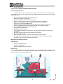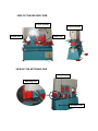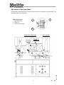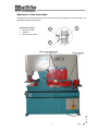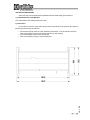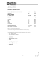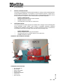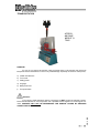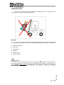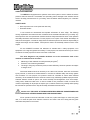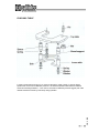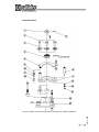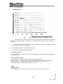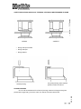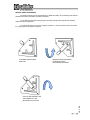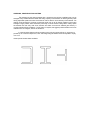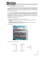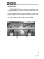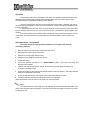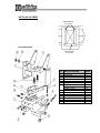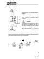
1
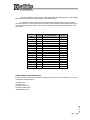
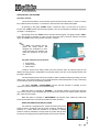
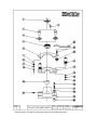
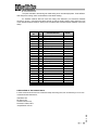
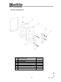
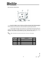
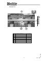
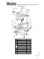
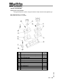
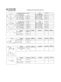
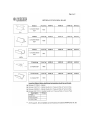
USER`S MANUEL MODEL HKM – 115 IRONWORKER MACHINE İİzzm Caadd.. 1166228855 B BU UR RS SA A // TTU UR RK KE EY Y miirr Y Yoolluu 2222..kkm mM Müüm miinn G Geennccooğğlluu C TTeell:: ++9900--222244--44770000115588 ((66 lliinneess ppbbxx)) W Weebb:: w ww ww w..ssaahhiinnlleerrm meettaall..ccoom m FFaaxx:: ++9900--222244--44770000777700 E Em maaiill:: iinnffoo@ @ssaahhiinnlleerrm meettaall..ccoom m S Sppaarree ppaarrttss & & sseerrvviiccee:: sseerrvviiccee@ @ssaahhiinnlleerrm meettaall..ccoom m CE DECLARATION We as ŞAHİNLER METAL MAKİNE END. A.Ş. İzmir Yolu 22.km Mümin Gençoğlu Caddesi Bursa / TÜRKİYE confirm that the machine HKM 115 Serial Number Production Year : : complies with E EC CM MA AC CH HIIN NE ES SD DIIR RE EC CTTIIV VE E 9988 // 3377 // E EC C rreeppllaacceedd w WG G aanndd wiitthh EEC C--D Diirreeccttiivveess 9911 // 336688 // EEW 9933 // 4444 // EEW G aanndd WG 9933 // 6688 // C CEEEE e g a t l o V w o L EEC 7 C-Low Voltage 733 // 2233 // EEW G WG EEC Diirreeccttiivveess 8866 // 118888 // EEW G WG Nooiissee LLeevveell D C -- N EEC Diirreeccttiivveess EEM C--D G WG MVV 8899 // 333366 // EEW and the machine also harmonized with the standards DIN EN 60204 Part 1 Name Position : Orhan ŞAHİN : General Director BURSA, on .............................. CONTENTS Page General notes 1-2 General warranty terms 3 Safety and accident prevention instructions 4 Transportation 5 Setting up the machine 6 Adjustment of the shear blade 7 View of the delivery side 8 Technical properties 9 Additional tools 10 Five work stations 11 - 12 Safety explanations 13 - 15 Operation of the machine 16 Punching table 17 Punching tools 18 - 19 Arrangement of the punch tools in general 20 - 21 Punch capacity 22 Safety precautions of the work stations 22 Steel bar and profile cutting installation 23 Shearing installation 24 Angle cutting installation 25 - 26 Grooving, grooving tools and parts 27 - 28 Stroke adjustment 29 Machine rod and lever readjustment 30 Hydraulic system, maintenance, lubrication 31 - 32 Hydraulic schema 33 – 34 Special accessories 35 Optional punch die and blade Blade adjustment and part list Electrical GENERAL NOTES 1. Introduction Thank you for choosing a Şahinler Sheet / Metal Working Machine. We are proud to have you in our long list of satisfied customers all over the world. This User’s Manual is absolutely for your safety and is essential for the machine to have a long production life. As long as you keep up with our Manual you will be able to run your machine smoothly and safely. Keep in mind that the machine is designed absolutely to perform maximum safety and for efficient working. In this Manual you can find instructions and information about: Correct installations of the machine Description of the functional parts of the machine Set-up and start-up adjustments Correct standard and scheduled maintenance Simple safety regulations and accident prevention. Therefore, as far as the user’s safety is concerned, in this handbook the possible risks connected with machine operation are pointed out as follows: Attention: Showing the risks of accident, if instructions are not followed. Warring: Showing the probable damages to the machine or equipment, if the instructions are not strictly followed. Note: It gives useful information. It is certainly necessary that the operator should read and understand all the Attention, Warring, Note specified in this Manual before starting with operation of the machine and before any lubrication or maintenance intervention On all steps of installation, operation and maintenance safety must be your first concern for the protection of yourself, other users and the service of the machine. In case of any failure please first refer to this Manual, and then if a solution cannot be found contact first of all the distributor where you purchased our product. Do not forget to refer to the drawings and the numbers for any spare part needed or to define any problem. Make sure you have the serial number and production year of the machine. Our technical staff will make their best to help you in the most convenient way. 2. Transport As soon as you receive the machine, check for any visible transport damages. Should there be any visible damages; report it straight away to the transporter company and of course Şahinler Metal Mak. End. A.Ş. or your supplier. Remove any protective crates around the machine and read the instructions on related chapters of this Manual carefully to set up the machine. If the machine is damaged while transport, immediately take some photographs for insurance claims. Take precautions while loading / unloading or moving the machine to avoid any injuries. Refer also to related chapter of this Manual for the best way of handling the machine. 3. Electrical Information All necessary connection procedure can be found on this Manual. Do not try to connect the machine before reading these procedures and fully understanding the drawings. For any unclear matters get in touch with Şahinler Metal Mak. End. A.Ş. or any of the Şahinler distributors. Have the machine connected by a qualified electric technician. For, as we made clear in the “general conditions of guarantee”, under no circumstances installing mistakes, including electrical connection mistake, can not be covered by guarantee agreement. Always turn off power before making any connections or disconnecting the machine. 4. Maintenance Your machine is designed and produced to work efficiently and smoothly. To achieve this you should also take care while operating the machine. Regard Maintenance sections to have the longest life from your machine. Try and use original spare parts where necessary and most importantly do not overload the machine or do not make any unauthorized modifications. 5. Safety Take all precautions possible to avoid any personal injury while using the machine. Keep in mind to protect the third party people around the machine. Refer to safety directives. GENERAL WARRANTY TERMS Your machine is covered by manufacturer’s guarantee for a period of 12 months from the date of purchase against manufacture defects. The warranty period does not exceed 18 months from the date of delivery from the manufacturer’s factory. Warranty covers only manufacture defective parts and / or components that are reported as “defective” by a Sahinler Technician or the Agent Technician and must be reported to Sahinler in writing by fax or email. The manufacturer is responsible for the supply of free of charge spares only and cannot be held responsible for loss of work. Shipping and customs fees for the spare part must be paid by the end-user. If a technician travel is necessary Sahinler will not charge for labor and workmanship costs but the customer must pay traveling and accommodation charges. A Warranty claim does not relieve the Customer from payment obligations. The Customer can not ask or demand any reimbursement of damage nor the Customer will have the right to extend or delay payment obligations nor the cancellation of order and the refunding of damages as the guarantee is given for the defective parts of the machine and not for the job. Note: All warranty claims must be applied with the Model, Serial Number and the Manufacture Year of the machine. -4- SAFETY AND ACCIDENT PREVENTION INSTRUCTIONS General Safety Instructions Following instructions are meant for the operator of the machine and it is the End-User’s responsibility to make sure the operator reads and understands the following and the User’s Manual for safe operation. Read the User’s manual before operating the machine. Always inform electric faults to electric technicians. Keep your working dress or long hair or necklace etc away from rotating parts. Make sure you know the position of Emergency Stop Buttons on the machine. Switch off the machine when NOT working. Work with necessary safety clothes if necessary (safety shoes, glasses , earplugs etc). Control the Safety features before working and ensure they are working properly. See and understand Safety Labels on the machine. Perform periodic maintenance. DO NOT overload the machine. If you see abnormal behavior of the machine, stop the machine and inform your supervisor immediately. Be careful of other people around the machine during operation. Never modify electric unit. Never remove any mechanic or electronic safety features from the machine. Be extremely careful during transport or re-placement of the machine and follow transport instructions in the manual to safety handle the machine. Machine Specific Safety Instruction Safety Features Position of Emergency Stops. Position of Safety Labels. Position of the operator during operation. Danger zones We recommend you to use upper listed rules. If you use upper listed rules, we hope you will not take industrial accident. Shows danger zones below the picture and these zones workstation of the machine. You don’t touch into the danger zones -4- SAFETY AND ACCIDENT PREVENTION INSTRUCTIONS General Safety Instructions Following instructions are meant for the operator of the machine and it is the End-User’s responsibility to make sure the operator reads and understands the following and the User’s Manual for safe operation. Read the User’s manual before operating the machine. Never touch rotating or moving parts. Always inform electric faults to electric technicians. Keep your working dress or long hair or necklace etc away from rotating parts. Make sure you know the position of Emergency Stop Buttons on the machine. Switch off the machine when NOT working. Work with necessary safety clothes if necessary (safety shoes, glasses , earplugs etc). Control the Safety features before working and ensure they are working properly. See and understand Safety Labels on the machine. Perform periodic maintenance. DO NOT overload the machine. If you see abnormal behavior of the machine, stop the machine and inform your supervisor immediately. Be careful of other people around the machine during operation. Never modify electric unit. Never remove any mechanic or electronic safety features from the machine. Be extremely careful during transport or re-placement of the machine and follow transport instructions in the manual to safety handle the machine. Machine Specific Safety Instruction Safety Features Position of Emergency Stops. Position of Safety Labels. Position of the operator during operation. Danger zones We recommend you to use upper listed rules. If you use upper listed rules, we hope you will not take industrial accident. Shows danger zones below the picture and these zones workstation of the machine. You don’t touch into the danger zones -4- VIEW OF THE DELIVERY SIDE Shear cylinder Punch cylinder Punch Unit Shear Unit VIEW OF THE NOTCHING SIDE Lever Group Notching Unit Hydraulic Unit Adjustment of the shear blade The adjustment of the shear levers should be carried out before any adjustment of the shear blade. The adjustment explain as shown below. Explanation of figure 3 1 1. Adjustment screw 2. Safety nut 3. Bronze pressure plate 2 Shear lever adjustment HKM115 -3- Not to tension Adjustment of the shear blade The adjustment of the shear levers should be carried out before any adjustment of the shear blade. The adjustment explain as shown below. Explanation of figure 1 3 1. Adjustment screw 2. Safety nut 3. Bronze pressure plate 2 Shear lever adjustment -3- Not to tension SETTING UP THE MACHINE Ask for the help of an experienced and qualified technician while setting up the machine. 1-) Fundamental Plan of the Machine Four holes (Refer to the drawing below) Dia.15mm 2-) Instructions For an effective machine, the position and the base of the machine are important. Be careful on these points while placing the machine: The machine must be placed on a flat, preferably cement base. To fix the machine use bolts. There must be plenty of room all around the machine for easy working. The machine height is ideal for any workingman. There must be plenty of Light on top of the machine 855 1830 1870 HKM 45 HKM 60 HKM 65 HKM 85 HKM 115 HPM 65 HPM 85 DELİK ZIMBASI PUNCHING Max. Kalınlıkta çap Diameter x max. thickness Ø22x15mm Ø28x15mm Ø26x20mm Ø33x20mm Ø34x26mm Ø26x20mm Çap x kalınlık (Øxt) Diameter x thickness Ø38x8mm Ø38x11mm Ø57x10mm Ø55x12mm Ø55x16mm Ø55x10mm Ø55x12mm Min. Kalınlıkta çap (Özel) (*) Diameter x min. Thickness Optional) (*) Ø100x3mm Ø110x3mm Ø110x3mm Ø110x5mm Ø110x5mm Ø110x3mm Ø110x5mm İş kursu Stroke 50mm 55mm 55mm 80mm 80mm 55mm 80mm Kurs adeti (20mm) Stroke count in (20mm) x 20 x26 x 25 x25 x25 x25 x25 Oluk derinliği Throat depth 175mm 220mm 305mm 355mm 355mm 625mm 625mm Çalışma yüksekliği Working height 940mm 940mm 1030mm 1050mm 1050mm 1075mm 1050mm MAKAS SHEET METAL SHEAR Düz sac Sheet metal 200x15mm 200x20mm 300x20mm 380x20mm 380x25mm Düz sac Sheet metal 300x12mm 300x15mm 375x15mm 480x15mm 600x15mm Bıçak uzunluğu Blade lenght 316mm 317mm 380mm 482mm 610mm Açılı Kesim Shearing with angle 80x10mm 80x10mm 100x15mm 120x15mm 120x15mm Çalışma yüksekliği Working height 940mm 940mm 890mm 900mm 900mm 150x150x18mm 100x10mm 100x10mm PROFİL KESME MAKASI ANGLE SHEAR Dik köşebent (90º) Angle section (90º) 100x100x10mm 120x120x12mm 130x130x13mm 150x150x15mm Açılı köşebent (45º) Angle section (45º) 70x6mm 80x8mm 70x10mm 80x8mm 80x10mm Çalışma yüksekliği Working height 1140mm 1140mm 1130mm 1155mm 1160mm DOLU MALZEME MAKASI STEEL BAR SHEARING Yuvarlak / Dörtköşe Round / Square ÇENTİK AÇMA NOTCHING Ø30mm-25mm Ø40mm-35mm Ø45mm-45mm Ø50mm-50mm Ø33x20mm Ø55mm-50mm Malzeme kalınlığı Thickness 8mm 10mm 10mm 13mm 13mm Genişlik Width 35mm 42mm 45mm 52mm 60mm Derinlik Depth 75mm 100mm 90mm 100mm 100mm V Derinliği V Depth 60mm 60mm 60mm 70mm 80mm Köşe flanşı Angle flange 80x8mm 100x10mm 100x10mm 100x13mm 100x13mm Çalışma yüksekliği Working height 940mm 940mm 890mm 890mm 900mm ÖZEL KALIPLAR OPTIONAL TOOLS U - I profil bıçakları U-I Section blades 80x45mm 80x45mm 130x65mm 160x90mm 200x100mm T profil bıçakları T Section blades 40x6mm 80x10 90x12mm 100x12mm 120x12mm Özel çentik takımı Special V-notching tooling 100x100x8mm 100x100x10mm 100x100x10mm 100x100x13mm 100x100x13mm 100x100x10mm 100x100x13mm 100x12mm 150x12mm 250x15mm 250x20mm 250x22mm 250x15mm 250x20mm 500x3mm 500x3mm 700x3mm 500x3mm 500x3mm 125mm 125mm V kıvırma Lama kıvırma max. V bending Press brake Bar bend. max. Capacity Sac kıvırma max. Çentik kısmında zımba Çene derinliğ Sheet bend. max.capacity Punching on notcher Bar bend. max. Capacity max. Kapasite max capacity 85mm 110mm 125mm 125mm 125mm 18x12mm 20x12mm 38x8mm 38x10mm 38x12mm TEKNİK ÖZELLİKLER TECHNICAL DATA Motor gücü Motor power 4kW 4kW 5.5kW 7.5kW 7.5kW 5.5kW 7.5kW Ağırlık Weight 1300kg 1250kg 1600kg 2430kg 3100kg 1900kg 2900kg Makine ölçüleri Machine dimensions 1200x600x1400mm 1510x590x1570mm 1625x750x1800mm 1900x790x1910mm 1880x790x1990mm 1450x850x1614mm 1670x855x1763mm Basınç Power (Pressure) 45 ton 60ton 65ton 85ton 115ton 65ton 85ton 7 ADDITIONAL TOOLS PUNCHING AT THREADING STATION Maximum capacity ( Diameter x Max. thickness ) 34x26 [mm] Maximum capacity (Max. diameter x thickness ) 110x5 [mm] Throat depth 355 [mm] PROFILE CUTTING U – I Section blades 200x100 [mm] T Sections blades 120x12 [mm] Thickness Width Depth V Depth Working height 13 60 100 80 900 [mm] [mm] [mm] [mm] [mm] Special V-notching tooling 100x100x13 [mm] Sheet bending max. capacity 700x3 [mm] NOTCHING Based on material strength 45 [kg/mm2] The maximum punching pressure of this machine is 1150 kN ( 115 ton ) The following tools are included in the basic equipment of the machine; 1 C – Spanner 120/130 4,5,6,8,10,14,19 mm. Allen keys Punch adapter Punch holder Stamp and matrix ( 26 mm ) Scraper Round square blade ( 1 set ) Angle cutting blade ( 1 set ) Profile cutting blade ( 1 set ) Notching tools -7- FIVE WORK STATIONS 1. 1-PUNCHING STATION All punching operating are processed by means of hydraulic power thus giving the machine the ability to punch very efficiently and silently. It can either be used to punch thick materials or thin materials in layers together. Punching is silent, powerful, efficient. The waste materials in layers together. The punching table consists two parts. First is the punching flange. The second is holder. The holder is a device that holds the material after punching not to come back with the punch. It must be equally adjusted or it can break the punch. There are different holders for different materials. However the standard holder which we supply is suitable for punching is between 6-55 mm. 2. SAFETY PRECAUTIONS All power and depth and other adjustment must be done under full control of an experienced technician Please check all the moving parts before working Check the punch and die that they are in the same direction Adjust the holder equally and according to the material always use the protective plastics on small and accuracy needing works use special protection while replacing the punch or die or holder shut the main switch never leave the machine unattended do NOT overload the machine SHEARING STATION The shearing unit has been equipped with a simple and robust fixing installation, which can be adjusted for any material thickness within the cutting the cutting capacity of the machine. A shearing up to 450 for flat bars or the cutting of the flanges of angle profiles, which have previously been cut at inclined-angle cutting stations. The shearing blades constructed for mass production can be used on both sides ( the upper blade has 2 cutting edges, the lower blade has 4 cutting edges ) and ensure a clean cutting with the minimum deformation, from the full capacity till a material thickness of only 2 mm. 3. SAFETY PRECAUTIONS Always use the bolder Never place any part of your body under the blade Do NOT overload the machine CUTTING STATION This station enables the cutting of big angles with a capacity of up to 900 and smaller angles up to 450. The angle between 450and 900 will be obtained, these will be cut first at 900and then at the shearing station of the flange will be cut at the required angle. The fixing installation supports the material in a manner to provide a correct cutting. SAFETY PRECAUTIONS Never place your hand or fingers inside the blade. Do NOT overload the machine Use holder fitted on this station for a better work 4. PROFILE CUTTING STATION The machine are equipped as standard with the blades for cutting round and quadrangle bars. Through additional equipment, it is possible to cut at the machine U-section, I-section and Tsection profiles in this clearance. The blades are held by simple squeezing jaws which ensure an easy equipment arrangement at the machine without any detailed adjustment. 5. SAFETY PRECAUTIONS Never place your hand or fingers inside the blade. Do NOT overload the machine Use holder fitted on this station for a better work NOTCHING STATION The notching station has been equipped as standard with a rectangle unit and threading table having adjustable counter holders, which enable a repeatable positioning. Additional installations are available for narrow widths or V notching of angles up to 450 (V). Furthermore, it is possible to have units for forming at bar ends and for easy notching works. SAFETY PRECAUTIONS Never put any part of your body under the blade Use protective gloves or protective cages for very small works Do NOT overload the machine SHOWS OF THE FIVE WORK STATIONS STANDARD SPECIFICATIONS Punch and die Ø26 Punch holder Flange cutting blade Notching blade Centralized lubrication Crescent key User’s manual TRANSPORTATION APPROX MACHINE WEIGHT 3,1 TONS DAMAGES As soon as you receive the machine, make a general check on the machine anal inform the transporter and the manufacturer in case of any visible damage. Especially be careful on these points; a) Visible mounted tools b) Tools in the c) Safety guards d) Oil gauge e) Main power knob f) Foot pedal cable Attention: If you see any visible damage on electric components, do NOT connect the machine to power. Inform the manufacturer as soon as possible. Ask a qualified electric engineer for connecting the machine. SAHINLER WILL NOT BE RESPONSIBLE FOR DAMAGE CAUSED BY IMPROPER CONNECTION OF ELECTRICS. TRANSPORTATION There is a ring mounted on top of the machine for transport purposes. You mount the chain or rope to this ring for all kind of displacement purposes. DAMAGES As soon as you receive the machine, make a general check on the machine anal inform the transporter and the manufacturer in case of any visible damage. Especially be careful on these points; a) Visible mounted tools b) Tools in the c) Safety guards d) Oil gauge e) Main power knob f) Foot pedal cable Attention: If you see any visible damage on electric components, do NOT connect the machine to power. Inform the manufacturer as soon as possible. Ask a qualified electric engineer for connecting the machine. SAHINLER WILL NOT BE RESPONSIBLE FOR DAMAGE CAUSED BY IMPROPER CONNECTION OF ELECTRICS. SAFETY EXPLANATIONS The HKM-115 is equipped with a hydraulic check valve system in order to relieve the excess pressure when the machine is overloaded, thus preventing serious damage to the machine and the worker. All safety precautions are for your safety, which we believe will be obeyed by our customers unasked. SAFETY UNITS Quick stop button use on the panel and main body Protective barriers In this manual are summarized the important information for work safety. The following security explanations and instructions are considered as the essential information for your safety. Any and all persons who must operate the machine should be firstly trained well in terms of the operation and safety information and instructions. For this purpose, more copies of this manual shall always be asked from the supplier. It should be clearly fixed out that which persons will have the responsibility to change and arrange tools and blades. These persons need to be essentially trained in terms of this subject. All the SAHİNLER machines are delivered as standard with a safety equipment, such equipment is for a high and general work safety. For this purpose, the machine should only be used in accordance for those purposes for which it has been constructed. The most dangerous and probable deviations as to the construction limits of the machine are estimated to be as follows: 1. 2. 3. Machining of other materials as unalloyed steel (45 kg/mm2) Erroneous use of the fixing installation Punching or fixing very small work pieces, as these will easily cause the operators be subject to danger zones. Should the additional tools be necessary to be used on the machine, which are not foreseen by the producer, it should be re-verified whether or not there is sufficient safety and security against work accidents. For this purpose, the producer should be contacted for advice when deemed necessary. All the maintenance works should be carried out by sufficiently qualified expert personnel. Particular attention should be paid to the correct assembly and arrangement of the hole stamps, cutting cases, blades and other tools. In order to enable us and yourselves to fulfill our mutual and common responsibility for all people, we request you to read this manual very carefully before putting the machine into operation and to obey all the safety information and instructions. Attention: ALL THE PARTS OF THE MACHINE DYED IN RED ARE DANGER ZONES AND PARTICULAR ATTENTION SHOULD BE PAID IN SUCH ZONES ! All the operators should be instructed in order not to place their fingers or other body parts near, in or under the parts of the machine colored in red. There is the risk of losing the body parts when these are placed in such zones ! All the safety components and fixing installations that should be removed for maintenance purposes, should be remounted again before the machine is reoperated. The operators should wear the clothing described by the employer. The producer recommend the use of protection eyeglasses against eventual stamp breaks and shoes with steel covering in order to prevent foot of the operator against falling materials. SAFETY RULES 1. The assembly and adjustment works, tool changes and maintenance services shall only be realized by the technical personnel qualified for this purpose, who should strictly obey the instructions of the producer. 2. Remove any oil remaining, cuttings and other impurities from the working zone where such remaining might be left the previous operator. 3. Before the starts working on the machine, the operator should make sure that all the tools are in a perfect condition. 4. Any leakage and order of hole stamps and cutting cases, blade tolerances etc. should be checked after each tool change and be readjusted if necessary. 5. The scraper should always be adjusted according to the material resistance to be machined. Unequal scraping forces can easily result with tool breaks. 6. Never punch any material which stronger than the diameter of the hole stamp. In this case, the hole stamp can be overloaded and easily break. 7. Always punch trough holes. Never punch base holes, unless the tool is clearly foreseen for this purpose. The lateral elongation force, which occurs during punching of the base holes, might excessively press the hole stamp against the cutting case and consequently an easy break might result. 8. The machine has been designed in a manner to work with the pieces which can be placed without having subjected the fingers or hands into the danger zone. For punching, mortising and profile cutting of the short pieces ( for instance small sheet metal parts ), special tools, scrapers and security components are pieces should be placed into the machine and taken back suitable holding tools. 9. Regularly check the screw connections and other fixings of all the blades and other parts as well as the safe seating of the hole stamp and cutting cases. For example, should the hole stamp ( punch ) get loose during the operation, there occurs the danger that the hole stamp inclined over the cutting case so that the tool might break. 10. Before each tool change, make sure that the machine is disconnected from main switch. 11. Completely disconnect the machine from the net before you carry out any maintenance work. 12. Never let the machine function without any inspection. 13. When you perform works where big forces are existing, the work piece should be additionally protected through a block having an assembled roll or similar installation, which is to be placed on the machine. 14. The machine capacity shall never be exceeded. For this purpose, check the" technical data" on this rules and compare the values with the information given on the manufacture plate. All the capacity information is based on a material having a resistance of 45 kg/mm2 15. Should the hydraulic circuit flow be overloaded, the hydraulic oil will be led back to the reserve tank over the overload valve until the pressure gets down again to the normal level. Attention: HOWEVER, IT IS. NECESSARY TO UNDERLINE THAT IT MIGHT BE DANGEROUS TO USE THE OVERLOAD VALVE AS A " SAFETY VALVE " IN ORDER TO EXCEED THE MACHINE CAPACITY. The producer presents all the instructions for a work protection and safety and hopes to have a good and full calibration with you, the users, in order to ensure that the maximum Level of safety could be obtained. CONTROLS BEFORE PUTTING INTO OPERATION 1. Press on the green " START " button in order to start the machine. In order to ensure this, make sure that the red off button ( " STOP" ) rotates clockwise (or directly to draw). 2. Make sure that the entries for hole stamp and cutting case are safety fixed. 3. At the command table, change the status from " NORMAL" to " ADJUSTMENT " ( Consider that the readjustment course is not automatic at this position. When you leave the foot pedal loose, the machine does not return to standby, rather it simply gets left). 4. Make sure that the course limiter allows a maximum course. Now, press on the foot pedal so often that the hole stamp stays in the cutting case. Take care that the hole stamp is regularly arranged with the cutting case. 5. Change the position from “ADJUSTMENT” to “NORMAL” at the command board. Now the machine gets automatically back to the standby position. 6. Check whether or not single cylinder perform, full course. Make sure that, no-hydraulic pressure occurs at the and of related course. In order to ensure that there is no air available in the hydraulic system, repeat the process several times (air might enter here during transport). Verify all tubes, hoses connections, branching and reserve tank for eventual hydraulic leakage. 7. 8. Fix again all the protection parts and remove all loose subjects from the working zone of the machine The machine is now ready for your job. PUNCHING TABLE In order to break the punching tool, you must use this table ( holder ) wisely. It must be always equaled and must be set for different pressures. The distance between lower table and material should be something between 1- 3 mm. Also to have the tool efficiently work the biggest part of the material should be covered by lower body during operation. PUNCHING TOOLS The part numbers in the above given figure 1 belong to the standard equipment. The parts indicated in the below given table belong to the standard equipment. Some different hole stamps and cutting cases are illustrated on the lateral drawing. As standard material, a Ø26 mm hole and cutting case delivered ( the maximum diameter amounts to Ø38 mm ). Adjust the hole stamp centrally so that an equally rotating cutting distance of 5 % of the material thickness remains. Never punch a material that is thicker than the diameter of the hole stamp. Assembly No 1 2 3 4 5 6 7 8 9 10 11 12 13 14 15 16 17 Quantity Part Identification Brand 1 1 1 1 1 1 1 2 1 1 1 1 2 2 2 2 1 Pressure plate Passing spring Hole stamp Adapter Specific nut Top scraper plate Scraper head Scraper support Distance piece Spring Washer Soc. head cap bolt M10x35 Washer 12 mm Spring ring Counter washer 12 mm Support tensioning Matrix holder Sahinler OEM Sahinler Sahinler Sahinler Sahinler OEM Sahinler OEM OEM OEM OEM OEM OEM OEM OEM Sahinler LUBRICATION OF THE PUNCH TOOLS In order increase the service lives of the hole stamp and cutting case, we recommend you to use one of the below listed lubrications; Shell Garia 927 BP Servora 68 Castroll llobroach 219 Duckharns Adfomol EP7 Joseph Batson LB 733 OPERATION OF THE MACHINE Operation elements All the electrical delivery of the machine passes through the main switch. In order to connect this, rotate the switch clockwise. To confirm this, check that the control lamp starts lighten. By pressing on the green “START” button, connect the motor ( for the motor to be able to function, the “STOP” button should be disconnected. This can be realized by rotating the red button clockwise ( or drawing this ). By pressing on the red “STOP” button, the motor will be stopped. The lightly pressed “STOP” button gets locked at command. In order to loosen the button and to cause the machine to function again, the “STOP” button will be turned clockwise ( or drawn ). Note: The machine has two pedals and double pistons. We designed two workstations to work at the same time, two operators can make two operations at the same time. The pedal switch has three positions: Over position central position lower position If pedal is driven till the lower position and there remains fixed, the machine gets into the deepest punching position. Nevertheless, the machine doesn’t turn back to the standby position until the pedal is left loose. The central pedal position allows the operator to effect unlimited positioning including over and down course. This central position is very practical because it allows the operator to carry out touching so that the work piece can be optimally positioned. The switch “NORMAL / ADJUSTMENT” ensures that the machine is operated at touch operation or performs production at normal functioning. When the switch is arranged on “NORMAL” , the machine performs a normal and full work cycle at each action of the foot pedal, that means the punch moves to the lowest position and then gets again into the standby. When the switch is arranged to “ADJUSTMENT” the machine stops. When the pedal is left loose, the automatic back course at this position has been cancelled. REGULAR LUBRICATION INSTALLATION The machine is equipped with a central lubrication pump under pressure which is located at used, the system should be adjusted to a pressure of 1-3 bars. When the machine is at operation, a suitable pressure would be maintained, through which the system will get back into the previous filling pressure (approximately each 30 to 60 minutes). ARRANGEMENT OF THE PUNCH TOOLS IN GENERAL The big punch bearing surface and the removable front block have been constructed in manner to allow a very wide range punch works: Through the optionally obtained tools, the big holes in any form up to the diameter / quadrate as it is indicated in the capacity table can be produced. In addition, machining at overhanging position, with the removed front in addition, during machining at overhang, with the removed front block, the of U profiles of double T supports having diameters or eventually diagonals up to 38mm highest capacity can be punched. The punching stamp is held though a holding ring, according to the size of the stamp ( punch ) one or two of the delivered adapters can be used. The matrixes are fixed to the tensioning plate through a positioning screw. When the filled punch stamps and matrixes are be arranged, it should be paid attention to the screw is correctly placed on the machined surface of the matrix. In order to allow a suitable play area and to ensure that the material is taken out, the punch stamp scraper plate should be correctly adjusted, however it should not effect the stamp course. Attention should be paid to that the lower course limiting switch has been adjusted as per the instructions. When the holes are punched with sufficient material, a flat contact occurs at both sides of the scraper plate. The scraper forces can be important and unbalanced scraper forces can lead to the break of the punch stamp through the contact with a side of the scraper. No material should be punched which is thicker than the stamp diameter. The quality of the hole is a direct finger appearance on the situation of the punch stamp and matrix. When the scraper fingers are used for very big holes or irregular forms, the fingers should be equally position and adjusted in order to prevent and unbalanced scraper load. Additional tools at this multi purpose work station allow bar and sheet metal bending works, edge threading, tube threading, tube threading and general column positioning works. - 14 - In order to install or change the punch tools you will need the following tools: Hook key Soc. head cap bolt key ( 6 mm ) Screw key ( 24 mm ) WHILE ORDERING SPARE STAMPS AND MATRIXES, PLEASE ALWAYS INFORM OF THE FOLLOWING : MODEL, TYPE AND MANUFACTURING NUMBER OF THE MACHINE. Below we explain step by step now the hole stamp and cutting case are changed : 1) In order to take out the cutting case, move the machine to a position where there is enough 2) Disconnect the machine at machine switch 3) Open the scraper, loose the coupling nut, fixing screws of the cutting case delivery plate and the M12 screws, which hold the cutting case. Remove the coupling nut together with the hole stamp and adapter. Remove the cutting case. 4) Place the required punch tool set. Make sure that the hole stamp and cutting case are correctly fixed. 5) Connect the machine and than position at “adjustment”. 6) Move the hole stamp slowly towards the cutting case. Push the cutting case delivery plate correctly so that the hole stamp and cutting case are completely arranged. 7) Adjust the cutting case delivery plate in a manner that the cutting distance which remains between the hole stamp and cutting case is fully equal and draw the delivery plate fixed in this station. 8) Check whether or not the receiving plate has been deviated during the drawing. If the cutting is not equal, you should repeat the point 8. as soon as the plate is fixed the cutting distance is equal, adjust the machine to “normal”. 9) Take the scraper back then adjust the distance between the scraper and cutting case according to the thickness of the material to the machined. 10) Adjust the course adjustment in such a manner that the shortest possible way should be left back. 11) In order to protect the operations, fix the macralon protection before you start working. - 15 - PUNCH CAPACITY HKM115 110 The diagram shows the punch capacity curves of the XS-series depending on the material thickness and stamp diameter. ( Based on a construction steel having a traction resistance of 45kg/mm2). Diameter of the punch stamp D (mm). During calculation of the punch capacity it should proceeded according to the following formula: P = SHEARING SURFACE x TRANTION RESISTANCE P D S TRANTION RESISTANCE A calculation example : A 20 mm hole will be necessary in a 12 mm thick homogenous steel sheet metal having 45kg/mm2 traction resistance. This is valid the following: Punching pressure = Shearing surface x traction resistance x 0.0098 and Shearing surface = Volume of the punch stamp x material thickness ( so the traction resistance Amounts to 45kg/mm2, 0.0098 is the fixed value for the calculation of kg/mm2 on KN accordingly : 20x 3,142x12x45x0,0098 = 333 KN ( 33,3 Tons ) Attention : Never punch with a hole stamp which is thinner than the material to be machined. - 16 - SAFETY PRECAUTIONS ON EACH OF THE WORK STATIONS IS WRIITEN UNDER ITS NAME WRONG CORRECT Wrong sized punch holder Wrong sized part Wrong distance Normal punching Very small punching, which requires special eccentric die and tool FLANGE PUNCHING You can use the standard tool for all kind of punching, however for flange punching like pictured above (right side), you have to order us a new set of eccentric die and tool. ANGLE CUTTING INSTALLATION This work station allows the cutting of big angles of 900 as well as cutting of the angles smaller than 450. In order to cut angle profiles, the material is placed into the cutting zone through the fixing installation and the support screw is adjusted to the corresponding material thickness. Nevertheless, one should pay attention here in that longitudinal move of the profile still remains possible. For the inclined cutting at 450, the angles should be first cut on the length where the delivery for the cutting of edges is also foreseen. Please the first and in the blade, here the highest support position will be used. Now cut about 6 mm from the end of the material, while you mountain 450 at vertical position. Now place the other and in the blade, here the left support position is used and then cut the material longitudinally. For this purpose, 450 should be maintained for from surface position of the machine. In order to obtain other cutting angles between 450 to 900 first cut the angle profile at length and then cut the flange as per the required angle at the shearing station. The cavity in the shear fixing installation allows that the angle profiles can be positioned for left or right side cutting. Here, attention should be paid to that the fixing installation gets adjusted to the related thickness. Each blade has four cutting edges and is held by the simple fixing screws. These blades should not be sharpened. After four rotation these should be replaced by new blades. WHILE ORDERING SPARE BLADES, ALWAYS STATE THE FOLLWING: MODEL, TYPE AND MANUFACTURING NUMBER OF THE MACHINE SHEARJNG, L PROFILE SECTION CUTTING The shearing unit has been equipped with a simple and strong fixing installation that can be arranged at any material thickness within the cutting capacity of the machine. A shearing delivery table having adjustable quides has been constructed in order to allow a correct delivery of the material. The guiding can be arranged in a manner to allow the angle cuts up 45º for fiat bar material or the cutting of flange of angle profiles, which have been previously cut at the inclined cutting station. Always place the material from the entry side of the machine and make sure that the material gets fixed by a correctly adjusted fixing installation. if a full cutting is required, the biggest possible dimensions for the material to be cut at angles, amount to 80x80x10. In case the shear blade should be grounded, grind only the cutting surfaces. A re-grinding is possible up to a maximum depth of 0,8 mm. After the grinding the blades should be adjusted to a play of 0.1 mm. ANGLE CUTTING INSTALLATION This work station allows the cutting of big angles of 900 as well as cutting of the angles smaller than 450. In order to cut angle profiles, the material is placed into the cutting zone through the fixing installation and the support screw is adjusted to the corresponding material thickness. Nevertheless, one should pay attention here in that longitudinal move of the profile still remains possible. For the inclined cutting at 450, the angles should be first cut on the length where the delivery for the cutting of edges is also foreseen. Please the first and in the blade, here the highest support position will be used. Now cut about 6 mm from the end of the material, while you mountain 450 at vertical position. Now place the other and in the blade, here the left support position is used and then cut the material longitudinally. For this purpose, 450 should be maintained for from surface position of the machine. In order to obtain other cutting angles between 450 to 900 first cut the angle profile at length and then cut the flange as per the required angle at the shearing station. The cavity in the shear fixing installation allows that the angle profiles can be positioned for left or right side cutting. Here, attention should be paid to that the fixing installation gets adjusted to the related thickness. Each blade has four cutting edges and is held by the simple fixing screws. These blades should not be sharpened. After four rotation these should be replaced by new blades. WHILE ORDERING SPARE BLADES, ALWAYS STATE THE FOLLWING: MODEL, TYPE AND MANUFACTURING NUMBER OF THE MACHINE MITRING ANGLE 45 DEGREES Since the introduction of the requirements for health and safety, the accessibility and distance between hold-downs and blades have been amended. To this effect the operation cutting angle in the angle cutting station requires the following simple hold-down adjustment. Once the hold-down is secured for cutting as position 3, it is also possible use the hold-down for cutting angle at 90 degrees if required. STANDARD HOLD-DOWN POSITION ROTATE AND SECURE THE HOLD-DOWN TO THE MACHINE FOR CUTTING REMOVE THREE SECURING SCREWS & INVERT HOLD-DOWN AS ABOVE SHEARJNG, PROFILE SECTION CUTTING The shearing unit has been equipped with a simple and strong fixing installation that can be arranged at any material thickness within the cutting capacity of the machine. A shearing delivery table having adjustable quides has been constructed in order to allow a correct delivery of the material. The guiding can be arranged in a manner to allow the angle cuts up 45º for fiat bar material or the cutting of flange of angle profiles, which have been previously cut at the inclined cutting station. Always place the material from the entry side of the machine and make sure that the material gets fixed by a correctly adjusted fixing installation. if a full cutting is required, the biggest possible dimensions for the material to be cut at angles, amount to 80x80x10. In case the shear blade should be grounded, grind only the cutting surfaces. A re-grinding is possible up to a maximum depth of 0,8 mm. After the grinding the blades should be adjusted to a play of 0.1 mm. Shows special section blades available STEEL BAR AND PROFILE CUTTING INSTALLATION In this clearance, various profiles can be cut–round and quadrant profiles, angle profiles with unequal levers, U profiles, double T supports etc. The blades for cutting the round and quadrate section have been constructed as a part of the standard equipment and have various size clearances. The smallest clearance that can contain the material should be chosen so that a complete and well supported cutting can be obtained. In order to replace the blades, the material supports should be removed. For this purpose, the four screws that fix the blade hooks are loosen, the blade hooks are taken out and the screws are pulled out. Here it is possible to observe that the mobile blade is smaller than the fixed one. Consequently a false assembly at the use of the installed support blades is prevented. Attention should be paid in the same time to the safety tap. This should be aligned in the mobile blade with the safety clearance in order to prevent a false positioning. Adjustment of the blade tolerance : Make sure that the mobile blade is well visible in the shear lever. Assemble the fixed blade in the frame in such a manner that this strongly presses against the mobile blade. Assemble the blade hooks solidly in the frame Pull out the six thread pins and then loosen at 1/5 rotation when you remove the counter nuts, hold the thread pin with the help of a internal hex. Key Steel bar shearing Shows special section blades available SHEARING INSTALLATION Blade adjustment / Blade Change: During the installation of the new blades, pay attention to that the mobile blades fully approach onto the shear lever. While the machine is disconnected, pull blades together with the soc. head cap bolts (Nr.1) totally onto the shear lever. In order the adjust the blades, more the shear lever so wide towards down that both blades get aligned. Now disconnect the machine. Adjust the mobile blade in such a manner that there remains a cutting distance of 0.1 mm. Pull the blade having conserved the right cutting distance (bolts, part no. 2 ). Note : Both blades can be used on both sides. You have four cutting edges. NOTCHING The threading station has quadrangles punch stamp as a standard equipment element and is delivered with a threading table complete with adjustable lateral and rear counter holders, which essentially simplify the repeatable positioning of the material. The sharp notching tools can also be constructed at this work station. Optianally, the units for narrower width of quadrangles or forms can also be delivered. Various units are also available for the forming of bar ends. A special feature of this work station is the possibility to fix some punch end units, that means tools for smaller punching works up to a punch pressure of 65 t ( characteristics can be supplied upon request ). In case the grinding of the notching stamp is necessary, only grind the side and front surfaces of the stamp. The matrixes have four cutting edges and should be turned in order to require new cutting. NOTCHING TOOLS – ADJUSTMENT The below described steps should be followed for the change of the notching ( threading ) blade set : 1. Move the stamp to the exit position ( that means fully open ) 2. Disconnect the machine at the main switch 3. Remove the scraper finger and the stamp 4. Remove the hole stamp and loosen the support 5. Fix the new stamp 6. Correct the machine and adjust it to “ADJUSTMENT” position. Fully lower the stamp and disconnect the machine 7. Take the hole ring into the support. Secure the front hole ring, then adjust the distance as illustrated in the below sketch 8. Secure the support on the machine after the adjustment of the front distance. Then adjust the side distances as illustrated in the sketch 9. Secure the side hole rings on the support. Check again the distances for safety 10. Connect to machine to loosen the stamp. Remount the scraper finger. adjust the machine course in order to have motion as small as possible. Note : The lateral distances of the stamp should be adjusted as per the adjustments illustrated in the sketch. Then the limiter will be arranged in such a manner that the lower edges of the hole ring will be touched by the bas. NOTCH ADJUSTMENT Literal distance 0.1-0.2 mm NOTCHING PARTS Front distance 0.1-0.2 mm NO 1 2 3 4 5 6 7 8 9 10 11 12 13 14 PART DESCRIPTION Scraper finger Upper blade Lower blade Lower blade Holder Tensioning Hex. Screw M12x65 Spring disc 12mm Flat disc 12 mm Nut M12 Internal hex. Screw M10x25 Internal hex. Screw M10x30 Maden screw M8x20 Internal hex. Screw M16x40 Flat disc M16 Nut M16 PIECE 2 1 2 1 1 2 4 4 4 4 2 4 6 2 2 2 STROKE ADJUSTMENT In order to lock the lowering stroke ( that means repeated bending etc. ) you must adjust the stopper A towards side. In order to lock the upper stroke B, use the punch stamp with the foot pedal and hold this in the lower position. Now lift the foot up in order to verify the position. If necessary, a readjustment shall be foreseen now. Attention : All the adjustments to be made on the stroke limiter, can also be carried out by using, the leading mode. For this purpose, the punch and / or shear position is arranged in such a manner that the required position is obtained by the foot pedal and then the stoppers are adjusted upon request. After the adjustment process, you must cause the machine to function under normal tempo in order check the stoppers. In order to lock the back stroke of the shearing unit, use the shears with the foot pedal and hold them in closed position. Now you can adjust the stopper arrangement C. Then lightly lift the foot in order to check the position. If necessary, carry out a readjustment. C HYDRAULIC SYSTEM A 7.5 kW motor drives a hydraulic pump, which supplies the power cylinders on each end of the machine through regulation valves. The punch cylinder is directly connected to the punching unit, where the shear cylinder is connected through a turning lever. Hydraulic oil For this purpose are advised the oil types indicated in the machine plate. The oil filling and ventilation supports are located in the tank where access is provided after removal of the protection having cooling cavities located on machine base. Absorption filter The oil filter should be checked every twelve months. Access to the filter can be ensured after having dismantled the screws of the tank protection. If necessary the filter can be washed in paraffin. Impurity section After having taken out the lower machine body protection, the section located under the main chassis should be checked each year for dirt and impurities. Cleaning Under normal operation conditions, all the visible working parts should be regularly cleaned from foreign substances that can prevent a standard use of the machine. REGULAR MAINTENANCE Daily Maintenance; Before starting machine Check full level in tank – top up us necessary Check oil level in oil pump – top up us necessary Check condition of all blades, punch and die Check surrounding work area is tidy, remove and off-cuts, slugs from floor area Clean off any mill scale which may have collected around the cutting apertures Weekly maintenance; But depending on work load Examine power cable and food pedal cable for damage or chafing Check movement of machine is smooth when running under no load condition Monthly maintenance; Check arm adjustment for any slackness Yearly; Change hydraulic fluid, check the oil absorption filter for any dirt and impurities LUBRICATION HYDRAULIC FLUID Fill to top level of inspection glass. Use only mineral oil as recommended or equivalent. You can select a oil at the table 1 OILING LUBRICANT Check oil level in pump reservoir daily, operate pump 2/3 times daily. Castrol Magna DR220 Shell Tomma T220 B.P. Energol GHI 220 Mobil Vactra oil No. 4 Esso Febis K220 Lubrication check Before operating machine, the following important checks should be made. The hydraulic fluid is at top level of inspection glass. The oil pump has been operated, and that there is oil pressure indicated, check oil level in pump HYDRAULIC OIL LIST On most of our machines hydraulic systems we use Grade 32 Hydraulic Oil and Grade 46 Hydraulic Oil Generally we recommend the use of Shell Tellus Nr.46 and BP Energol Nr.46 for hydraulic systems Brand DIN 51524 Specification 32 Grade Mineral Oil DIN 51524 Specification 46 Grade Mineral Oil Agip OSO 32 OSO 46 BP Energol HLP 32 Energol HLP 46 Castro Hyspin AWS 32 Hyspin AWS 46 Elf Elfolna 32 Elfolna 46 Esso Nuto H 32 Nuto h 46 Fina Hydran 32 Hydran 46 IP Hydrus 32 Hydrus 46 Mobil DTE 24 DTE 25 Q8 Haydn 32 Haydn 46 Shell Tellus 32 Tellus 46 Texaco Rando HD 32 Rando HD 46 Total Azolla ZS 32 AzollaZS 46 Table 1 MACHINE ROD AND LEVER READJUSTMENT After a preliminary working period ( about 5 to 6 days ), it will be necessary to carry out arrangement adjustments on the machine. Punch rod The arrangement of the rod will be realized with the help of a “rod leading plate”. This plate should be readjusted. The related adjustment screws are located at the exit side of the machine. In order to adjust the rod, proceed in the following manner : Remove the punch stamp Loosen the safety nuts Readjust the rod adjustment screw ( not to tighten too much ) Lock the screws with a safety nut The adjustment control is to be made through a few in and out movement ( about 6 times ) of the rod. Then the machine should be checked in adjustment mode. If the rod does not move here, the plate should be readjusted and the process must be repeated. Shear lever The machine should be disconnected before carrying out any readjustment works on the shear lever. The readjustment of the pressure lines should be carried out from the delivery side of the machine. For this purpose, proceed in the following manner : Loosen the safety nuts only of the three pressure line positions Until alight pressure is obtained, rotate the adjustment screws clockwise Tighten the safety nuts again and check the movement ability Attention : The grooving stamp and matrixes are now not any more arranged. Please adjust these again before the use of the machine. The part numbers in the above given figure 1belong to the standard equipment. The parts indicated in the below given table belong to the standard equipment. Some different hole stamps and cutting cases are illustrated on the lateral drawing. As standard material, Ø26 mm hole and cutting case delivered ( the maximum diameter amounts to 38 mm ). Adjust the hole stamp centrally so that an equally rotating cutting distance of 5 % of the material thickness remains. Never punch a material that is thicker than the diameter of the hole stamp. Assembly Quanti Part Identification No ty 1 1 Punch support 2 4 Soc. Head cap bolt 3 1 Stamp 4 1 Adapter 5 1 Specific nut 6 1 Top scraper plate 7 1 Distance piece 8 1 Spring 9 1 Washer 10 1 Soc. head cap bolt M10x35 11 2 Scraper support 12 1 Scraper head 13 2 Washer 12 mm 14 2 Spring ring 15 2 Counter washer 12 mm 16 6 Soc. head cap bolt 17 6 Counter washer 18 1 Washer 19 1 Matrix holder 20 6 T nut 21 1 Set screw 22 1 Matrix 23 1 Fixing wheel 24 1 Set screw 25 1 Hook key Brand Sahinler OEM Sahinler Sahinler Sahinler Sahinler OEM OEM OEM OEM Sahinler Sahinler OEM OEM OEM OEM OEM OEM Sahinler Sahinler OEM Sahinler Sahinler OEM OEM LUBRICATION OF THE PUNCH TOOLS In order increase the service lives of the hole stamp and cutting case, we recommend you to use one of the below listed lubrications; Shell Garia 927 BP Servora 68 Castroll llobroach 219 Duckharns Adfomol EP7 Joseph Batson LB 733 Steel bar cutting part list: NO 1 2 3 4 5 6 7 8 PART DESCRIPTION QUANTITY Mobile profile blade Fixed profile blade Hook Soc. head cap bold M20x50 Set screw M6x12 Set screw M12x40 Counter nut M12 Federing 20 mm 1 1 2 6 1 6 6 6 29 Blade adjustment / Blade Change: During the installation of the new blades, pay attention to that the mobile blades fully approach onto the shear lever. While the machine is disconnected, pull blades together with the internal hexagonal screws (3) totally onto the machine body, without the thread pins (4) press against the blade. In order the adjust the blades, more the shear lever so wide towards down that both blades get ( mobiles and fixed blades ) get aligned. Now disconnect the machine. Adjust the mobile blade in such a manner that there remains a cutting distance of 0.1mm ( the thread pins, part no.4 serve for the adjustment ). Pull the blade having conserved the right cutting distance ( screws, part no. 5 ). Note : Both blades can be used on both sides. You have four cutting edges. No Miktar 1 2 3 4 5 6 1 2 3 10 4 4 Parça adı Mobile angle blade Fixed angle blade Hex. soc. head cap bolt M16x45 Set screw M10x20 Hex. soc. head cap bolt M16x45 Spring washer 16 mm 30 Üretici Sahinler OEM Sahinler Sahinler Sahinler Sahinler BLADE PART LIST NO 1 2 3 4 5 6 7 8 9 PART DESCRIPTION Upper blade Lower blade Set screw M12x80 Washer 12 mm Spring washer 12 mm Nut M12 Set screw M12x35 Hex. soc. head cap bolt M12x35 Washer 12 mm 31 QUANTITY 1 1 5 5 5 5 15 5 5 NOTCHING PARTS NO 1 2 3 4 5 6 7 8 9 10 11 12 13 14 PART DESCRIPTION Scraper finger Upper blade Lower blade Lower blade Holder Tensioning Hex. Screw M12x65 Spring disc 12mm Flat disc 12 mm Nut M12 Internal hex. Screw M10x25 Internal hex. Screw M10x30 Maden screw M8x20 Internal hex. Screw M16x40 Flat disc M16 Nut M16 QUANTITY 2 1 2 1 1 2 4 4 4 4 2 4 6 2 2 2 SPECIAL ACCESSORIES Drilling of the I and U profiles During punching of the I profiles, change the standard scraper head with the lengthened type. Min. profile size 65 for I or U profile Max. profile size 120 for I or U profile NO PART DESCRIPTION 1 2 3 4 5 6 7 8 9 10 11 12 13 Hole ring ( 5 – 38 ) usable with stamp 9001 & 9004 Hole ring ( 3 – 19 ) usable with stamp 9000 & 9004 Hole ring holding plate Hole ring holding plate Adapter plate Adapter plate Support tensioning Matrix support Hex. soc. head cap bolt M16x60 T nut M16 Set screw M10x12 Set screw M8x12 Soc. head cap bolt M12x60 QUANTIT Y 1 1 1 1 1 1 2 1 4 4 1 1 2 PRESS BRAKE BENDING: Bar bending max. capacity: Sheet bending max. capacity: 250x22 mm 700x3 mm