1
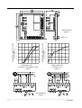
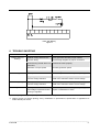
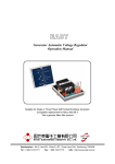
EA15A3H
Generator Automatic Voltage Regulator
Operation Manual
Self Excited Automatic Voltage Regulator
15 Amp 3 Phase Sensing AVR
Headquarters : No.3, Lane 201, Chien Fu ST., Chyan Jenn Dist., Kaohsiung, TAIWAN
Tel : + 886-7-8121771
Fax : + 886-7-8121775
URL : http://www.kutai.com.tw
1. SPECIFICATION
Sensing Input
Voltage
Frequency
Power Input
Voltage
Output
Voltage
Current
Resistance
180 ~ 500 VAC, 3 phase3 wire
50 / 60 Hz, selectable
Thermal Drift
0.03% per °C change in AVR ambient
External Volts Adjustment
± 15% with 1K ohm 1 watt trimmer
100 ~ 300 VAC, 1 phase 2 wire
Unit Power Dissipation
Max. 8 watt
Max. 90 VDC @ 240 VAC input
Continuous 15A
Intermittent 20A for 10 sec
Min. 9 ohm
Under Frequency Protection (Factory Setting)
60 Hz system presets knee point at 55 Hz
50 Hz system presets knee point at 45 Hz
Voltage Regulation
< ± 0.5% ( with 4% engine governing )
Soft Start Ramp Time
2 sec.
Voltage Build-up
Residual voltage at AVR terminal > 5 VAC
Dimensions
150mm L * 135mm W * 72mm H
Weight
867 g ± 2%
2. WIRING (Refer to Fig4, Fig5)
3. NOTICE OF USE
2.1 Terminals F+ & F−
−
The EA15A3H can be mounted in various place, like
generator control panel, switchgear cabinets, ect.
But prevent high temperature, high moisture, or
severe vibration places.
● The DC output port of the regulator
● F+ is positive normally connected to the field of
generator marked ‘F+’ , ‘F1’ or ‘J’
● F− is negative normally connected to the field of
generator marked ‘F-’ , ‘F2’ or ‘K’
See figure 1 for mounting dimensions.
The EA15A3H surface temperature will be over
60°C when operations. DO not touch the heat sink.
2.2 Terminals sensing
● The power and sensing port of the regulator
( Sensing voltage had been connected on 220 /
380 / 440 / 480V three phase from generator).
● Single phase will cause output voltage 27%
exceed nominal value.
2.3 Terminals EXT VR.
● For external voltage adjustment if required.
2.4 Terminals 50 & COM
● Under frequency protection selection
3.1 Startup Procedure
1. Ensure all the wire of the regulator are correctly
connected and the proper fuse (15A500V) is
installed.
2. Turn voltage potentiometer full anticlockwise
( lowest voltage level).
3. If used, turn external voltage potentiometer to the
middle position.
4. Turn stability potentiometer
(highest stability level).
full
clockwise
5. Connect a 110VDC meter across the field with
proper polarity.
● Connect a jumper from COM to the 50Hz terminal
for 50 Hz operation, or leave the two terminals
unconnected for 60Hz operation.
______________________________________________________________________________________
2
EA15A3H
6. Connect a 300VAC meter across line to neutral
of generator.
7. Start and run the generator at no load and rated
speed.
The generator output voltage should build up to a
minimum level if the voltage does not build up, It
may cause by low residual voltage of generator.
Refer to field flashing section in generator
manual.
8. Slowly adjust voltage potentiometer until the
generator voltage reach the proper value.
9. Turn the stability potentiometer clockwise until
instability is shown, and then turn it anticlockwise
slightly still both meter mention in (5) and (6)
shown stable.
10.Interrupt regulator power for a short time
(approximately 1 to 2 second). If the voltage still
stable, the adjustment is now completed.
Otherwise increase the stability slightly, repeat
procedure (10) until stability is reached.
4. ADJUSTMENTS
4.1 Frequency Roll-Off Adjustment
Connect a jumper from COM to the 50Hz terminal
for 50Hz operation, or leave the two terminal
unconnected for 60Hz operation. To reset the
frequency roll-off, proceed as follow :
1. Adjust the prime mover RPM to the desired
frequency compensation (corner frequency
roll-off ) point.
2. Adjust the front panel FREQ control until the
output voltage low about 5V than nominal
voltage. ( For 50Hz applications, the frequency
“roll-off” is factory preset to 45Hz, for 60Hz
operation, the frequency is 55Hz).
2. Rotation of the front panel STAB control in the
counter-clockwise (CCW) direction will speed
response time If rotated too much for CCW, the
generator voltage my oscillate (hunt).
3. Rotated the front panel STAB control CCW until
the system start oscillating and then rotate cw
just past the point where oscillation occurred.
5. FIELD FLASHING
When the regulator is operated with the generator for
the first time, the polarity of residual magnetism may
be reversed or too small to achieve the necessary
build-up voltage for the regulator. If reversing the field
connections does not induce build-up, and the residual
voltage is less than the specified value of 5 Vac, shut
down the Prime-mover and proceed with the following
steps :
1. With the Prime-mover at rest and the regulator’s
field output wires disconnected, apply a DC
source ( NOT grounded ) of not more than 3~12
Vdc with Positive to F+ and Negative to F-, in
series with a current-limiting resistor of 3~5 ohms
20 watt. (The set battery is a suitable source.)
2. Allow approximately 3 seconds before removing
the DC source.
3. With the voltage regulator disconnected ( wires 3
and 4 ), start the prime mover and measure the
“ residual ” voltage available at the auxiliary
winding. If this voltage is greater than 5 Vac,
reconnect voltage regulator, and voltage build-up
should be successful. If less than 5 Vac is
measured, repeat field flashing procedure.
4. If repeating steps a. and b. does not result in
generator voltage build-up, and residual is
greater than 5 Vac, replace voltage regulator.
4.2 Voltage Adjustment
1. Adjust the front panel VOLT to vary the generator
nominal voltage.
2. If used, a 1000Ω 1 watt potentiometer may be
connected to terminals EXT VR, refer to Figure4.
4.3 Stability Adjustment
1. Adjust the front panel STAB control the system
stable.
______________________________________________________________________________________
EA15A3H
3
Outline Drawing
Figure 1
UNIT : mm
120
GENERATOR OUTPUT VOLTAGE
(% OF NOMINAL)
GENERATOR OUTPUT VOLTAGE
(% OF NOMINAL)
120
100
80
50HZ
60HZ
60
40
20
0
10
20
30
40
50
100
80
60
40
20
60
FREQUENCY (HZ)
0
1
2
SOFT START (V/S)
Frequency compensation curves
Figure 2
Soft start curve
Figure 3
Wiring Diagram
Figure 4
______________________________________________________________________________________
4
EA15A3H
Flash with Battery
Figure 5
6. TROUBLE SHOOTING
SYMPTOM
Voltage does not
build up
Out voltage low
Out voltage high
Out voltage instable
CAUSE
CORRECTION
Residual voltage below 5VAC
Flash generator field with proper method
Incorrect wiring
Check wiring diagram for proper connection
Power/sensing or field wires not
connected
Connect the wires properly
Generator not up to speed
Increase generator speed
Over-excitation
Restart the generator
Poor adjustment is made
Read start procedure carefully and adjust again
Frequency roll-off
Increase generator speed
Incorrect voltage selection
Read user’s manual to select correct voltage
Poor adjustment is made
Read start procedure carefully and adjust again
Incorrect voltage selection
Read user’s manual to select correct voltage
Poor adjustment is made
Read start procedure carefully and adjust again
Field voltage requirement lower
the rang of regulator
Inquire our distributor to solve
※ Use only original supplied spare protection fuse for fuse replacement.
※ Please accept our sincere apology if any modification in performance, specification or appearance is
made without prior notice.
______________________________________________________________________________________
EA15A3H
5