1
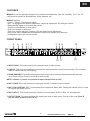
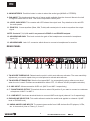
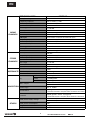
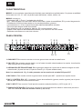
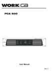
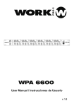
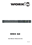
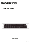
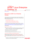
MMX 65
User Manual / Manual de Uso
Rev 13.05.01
EN
SAFETY RELATED SYMBOLS
WARNING:
TO REDUCE THE RISK OF FIRE OR
ELECTRIC SHOCK, DO NOT EXPOSE
TO RAIN OR HUMIDITY. DO NOT
REMOVE COVER. THIS PRODUCT IS
NOT INTENDED FOR USE OTHER THAN
STATED.
GRAPHICAL SYMBOLS EXPLANATION
This symbol, wherever used,alerts you to
the presence of un-isulated and dangerous
voltages within the product enclosure.
These are voltages that may be sufficient to
constitute the risk of electric shock.
External Connection
Always use proper ready-made insulated mains
cabling (power cord). Failure to do so could result
in shock or fire. If in doubt, seek advice from a
registered electrician.
Do not Remove Any Cover
This symbol, wherever used, alerts you to
important operating and maintenance
instructions. Please read.
Within the product are areas where high voltages
may be present. To reduce the risk of electric shock
do not remove any covers unless the AC mains
power cord is removed.
Protective Ground Terminal
AC mains (Alternating Current)
Covers should be removed by qualified service
personnel only.
No user serviciable parts inside.
Hazardous Live Terminal
ON: Denotes the product is turned on.
Fuse
OFF: Denotes the product is turned off.
WARNING
Describes precautions that should be observed to
prevent the possibility of death or injury to the user.
CAUTION
To prevent fire an damage to the product, use only
the recommended fuse type as indicated in this
manual. Do not short-circuit the fuse holder.
Before replacing fuse, make sure that the product
is OFF and disconnected from the AC outlet.
Protective Ground
Describes precautions that should be observed to
prevent damage to the product.
Before turning the product ON, make sure that it is
connected to Ground. This is to prevent the risk of
electric shock.
WARNING
Power Supply
Never cut internal or external Ground wires. Likewise,
never remove Ground wiring from the Protective
Ground Terminal.
Ensure that the mains source voltage (AC outlet)
matches the voltage rating of the product. Failure
to do so could result in damage to the product and
possibly the user.
Operating Conditions
Unplug the product before electrical storms occur
and when unused for long periods of time to reduce
the risk of electric shock or fire.
1
Always install in accordance with the manufacturer´s
instructions.
To avoid the risk of electrtic shock and damage, do
not subject the product to any liquid/rain or moisture.
Do not use this product when in close proximity to
water.
Do not install this product near any direct heat source.
Do not block areas of ventilation.
User Manual/Manual de Uso
MMX 65
EN
FEATURES
MMX 65 is a mixer specially designed for professional installations. With full versatility. The 1 HU 19"
rack format in perfect for discotheques, clubs, theatres, etc.
MMX 65 features:
- 6 Line, 1 Phono, 3 Microphone inputs.
- MIC 1 is equipped with talkover attenuator, sensitivity adjustment, EQ and gain control.
- Balanced Mic inputs on front and rear panels.
- Simple on/off switches on front panel.
- Dual zone assign for all inputs.
- Two zone outputs with gain, balance, EQ and stereo/mono adjustment.
- Both zones have unbalanced and balanced outputs with master gain reduction.
- Headphone output with volume control.
FRONT PANEL
6
4
5
7 8 9
2 1 3
12
13
10 11
1. INPUT GAIN. This knob controls the input gain level on each source.
2. ON/OFF. This push button allows to included the selected audio source into the mixing. The activation
state is marked with the LED lighting.
3. ZONE ASSSIGN. This switch determines which output zone is driven the selected audio sourced
(A for Zone A, B por Zone B and A+B for both zones).
NOTE: Controls 1,2 and 3 are present in input channels CH2 to CH7
4. MIC 1 GAIN. This knob controls the input gain for MIC 1 present in the front side.
5. MIC 1 EQ CONTROL. MIC 1 incorporates 3 tone equalizer (Bass, Mid, Treble) with central point, in order
to equlizer this audio source.
6. MIC 1 INPUT. This Combi connector allows to connect either XLR3 or Jack 1/4" microphones.
7. OUTPUT GAIN. This knob controls the output gain level on each zone, Zone A in this case. Zone B
has the same controls (7,8,9,10,11).
2
User Manual/Manual de Uso
MMX 65
EN
8. MONO/STEREO. Push this button in order to select the audio type (MONO or STEREO).
9. BALANCE. This knob controls the mix of stereo audio available from the channel. Move to the Left
or Right to select the L/R level. This knob incorporates central point.
10. LEVEL INDICATOR. This vumeter with LED shows the output level. Pay attention to the red LED
for audio peaks.
11. ZONE EQ. 3 tone equalizer (Bass, Mid, Treble) with central point in order to equalizer the output
signal.
NOTE: Controls 7, 8, 9, 10 and 11 are present in ZONE A and ZONE B outputs.
12. HEADPHONE GAIN. This knob controls the gain of the headphones connected in headphone
input (13).
13. HEADPHONES. Jack 1/4" connector which allows to connect a headphones for monitor.
REAR PANEL
R
65
Use only with a 250V fuse
16
15
14
13
12 11
10
9
8
7 6 5 4
3
2 1
1. TALKOVER THRESHOLD. Determines the point in which auto-talkover activates. The more sensitivity
adjustment you need to speak into your microphone to activate auto-talkover.
2. TALKOVER ATTENUATION. Sets the front panel MIC 1 to automatically reduce other source level
when the mic is used. Positions are available for either OFF, -12 dB and -40 dB (complete reduction)
3 - 8. MIC INPUT. Allows connection XLR3 mic (MIC 2 and MIC 3 respectively)
4 - 7. PHANTOM SELECTOR. This switch allows to select ON position if you want to connect a condenser
microphone in MIC 2 or MIC 3.
5 - 6. LINE INPUT. Use these terminal blocks to connect LINE level signal (channel 2 or 3 respectively).
9. PHONO/LINE SELECTOR. This switch allows to select the audio level applied on channel 4 (LINE
level or PHONO level)
10. UNBALANCED LINE INPUTS. To connect stereo audio from LINE devices like CD players, VCRs,
etc. in channels 4 (Line or Phono), 5, 6 and 7.
3
User Manual/Manual de Uso
MMX 65
EN
11. RECORD OUTPUT. Send the complete mix output signal to send to an external recording device.
12. UNBALANCED ZONE OUTPUTS. RCA connectors. The level is controlled by the zone knobs.
13. BALANCED ZONE A OUTPUT. XLR 3 connectors for ZONE A output. Its level is controlled by
ZONE A knob in the front side.
14. BALANCED ZONE B OUTPUT. Jack 1/4" connectors for ZONE B output. Its level is controlled by
ZONE B knob in the front side.
15. POWER SWITCH. Switch the unit on
16. MAIN CONNECTOR. Use the included IEC/Schucko cable to connect the unit in an adequate AC
outlet.
LATERAL SIDE
In the lateral side of the device, you can select the input voltage. Be careful to check the correct value
before connect the device.
4
User Manual/Manual de Uso
MMX 65
EN
TECHNICAL DATA
MMX 65
Microphone input
Frequency response
Distortion(THD+N)
input Sensitivity
Gain range
Max. input
MONO
SNR
CHANNELS Phantom power
LINE input
Frequency response
Distortion(THD+N)
input Sensitivity
Gain range
Max. input
SNR
LINE input
Frequency response
Distortion(THD+N)
STEREO
input Sensitivity
CHANNELS Gain range
Max. input
SNR
Microphone input
IMPEDANCES All other input
All other out
treble
EQ
middle
bass
XLR jack with balanced
20Hz to 22KHz,+/-2dB
<0.1% at +0dB ,22Hz~22KHz
-47.5dBu
-∞~10 dBu
-20 dBu
>75dBr A-weighted
+12V with mic in channel
3P Euroblock connector & balanced input
20Hz to 22KHz,+/-2dB
<0.1% at +0dB ,22Hz~22KHz
-10dBu
-∞~10 dBu
10dBu
>75dBr A-weighted
RCA jack
20Hz to 22KHz,+/-2dB
<0.1% at +0dB ,22Hz~22KHz
-10dBu
-∞~10 dBu
10dBu
>75dBr A-weighted
1.0kΩ
10KΩ or greater
120Ω
+/-12dB @12KHz
+/-12dB @1KHz
+/-12dB @80Hz
+26dBu XLR & TRS balanced
+22dBu RCA Un-balanced
OFF to 10dBu
>70dB @ 20Hz~22KHz A-weighted,
1 channel & master: max,the other channels :minimum
>65dB @ 20Hz~22KHz A-weighted﹑
1 channel & master: max,the other channels :minimum
100-120V~ 50/60Hz Fuse :T800mAL
220-240V~ 50/60Hz Fuse :T500mAL
25W
2.2 kg
483*44*192mm
Max. output
MIX SECTION
knobe range
Hum & Noise
Crosstalk
rated power supply voltage
OTHERS
rated power consumption
Weight
Dimensions
5
User Manual/Manual de Uso
MMX 65
ES
EN
SIMBOLOS DE SEGURIDAD
WARNING:
TO REDUCE THE RISK OF FIRE OR
ELECTRIC SHOCK, DO NOT EXPOSE
TO RAIN OR HUMIDITY. DO NOT
REMOVE COVER. THIS PRODUCT IS
NOT INTENDED FOR USE OTHER THAN
STATED.
EXPLICACION DE LOS SIMBOLOS GRAFICOS
Este símbolo, cuando se use, le alerta de la
presencia de una tensión peligrosa y no aislada
con el producto cerrado. Este voltaje puede
ser suficiente para constituir un riesgo de
descarga eléctrica.
Este simbolo, cuando se usa, le alerta de una
instrucción de uso o mantenimiento importante.
Por favor léala.
Terminal de protección de masa.
Conexionado Externo
Utilice un cable de alimentación aislado para el c
onexionado del producto. El utilizar de otro tipo
puede ocasionar descargas o fuego. Si tiene alguna
duda, consulte con un electricista experto.
No retire ninguna cubierta
Dentro del producto hay áreas con alta tensión
presente. Para reducir el riesgo de descargas
eléctricas, no retire ninguna cubierta a menos que
el cable de alimentación esté desconectado.
Alimentación AC (Corriente Alterna)
Las cubiertas deben ser retiradas por un técnico
cualificado.
Terminal peligroso (Tensión)
ON: Denota que el producto está encendido.
No hay elementos de control para el usuario en el
interior.
OFF: Denota que el producto está apagado.
WARNING
Fusible
Describe precauciones que deben ser observadas para
prevenir la posibilidad de daños o muerte en el usuario.
Para prevenir el riesgo de fuego o daños en el
producto, use sólo el tipo de fusible recomendado
e indicado en el manual No cortocircuite los terminales
del portafusible. Entes de sustituirlo asegúrese que el
producto está apagado y desconectado de la toma AC.
CAUTION
Describe precauciones que deben ser observadas para
prevenir daños en el producto.
Terminal de protección de tierra
Antes de encender el producto, asegúrese que está
conectado a tierra con el fin de prevenir riesgos de
descarga eléctrica o fuego.
WARNING
Alimentación
Asegúrese que la toma de alimentación principal (Toma
AC) tiene el mismo valor que la marcada en el producto.
En caso contrario podría sufrir daños tanto el producto
como el usuario.
Desconecte el producto antes de unas tormenta eléctrica
y cuando no vaya a usarlo durante largos periodos de
tiempo paras reducir el riesgo de descargas o fuego.
Nuca corte los cables de tierra internos o externos.
Asimismo nunca desconecte el cable de tierra de su
terminal de conexión.
Condiciones de Funcionamiento
Instale la unidad siempre de acuerdo a la instrucciones
del fabricante.
Para evitar el riesgo de descargas eléctricas o daños,
no someta la unidad a ningún liquido, lluvia o humedad.
No use la unidad cerca del agua.
No instale la unidad bajo una fuente de calor.
No bloque las tomas de ventilación.
6
User Manual/Manual de Uso
MMX 65
ES
EN
CARACTERÍSTICAS
MMX 65 es un mezclador especialmente diseñado para instalaciones profesionales. Con plena versatilidad.
Su formato de 1 HU 19 " rack, es perfecto para discotecas, clubes, teatros, etc
MMX 65 cuenta con:
- 6 entradas LINE, 1 Phono, 3 entradas de micrófono.
- MIC 1 está equipado con atenuador talkover atenuador, ajuste de sensibilidad, EQ y control de ganancia.
- Entradas de micrófono balanceadas en los paneles delantero y trasero.
- conmutadores on / off en el panel frontal para habilitar/deshabilitar entradas.
- Zona dual para asignar todas las entradas.
- Dos salidas de zona con ganancia, balance, EQ y ajuste estéreo / mono.
- Ambas zonas disponen de salidas balanceadas y con reducción de nivel master.
- Salida de auriculares con control de volumen.
PANEL FRONTAL
6
4
5
7 8 9
2 1 3
12
13
10 11
1. GAIN INPUT. Este mando controla el nivel de ganancia de entrada de cada fuente.
2. ON / OFF. Este pulsador permite incluir o no la fuente de audio seleccionada en la mezcla. La activación
está marcada con la iluminación LED.
3. ASIGNACION DE ZONAS ZONAS. Este interruptor determina A qué zona de salida se asigna el audio
seleccionado (A para la zona A, B para la Zona B y A + B para ambas zonas).
Nota: Los controles de 1,2 y 3 están presentes en los canales de entrada CH2 para CH7
4. MIC GAIN 1. Este mando controla la ganancia de entrada para MIC 1 presente en la parte frontal
5. MIC 1 (CONTROL EQ). MIC 1 incorpora 3 tonos de ecualización (graves, medios, agudos) con el punto
central para ecualizar a esta fuente de audio.
6. MIC 1 INPUT. Este conector Combi permite conectar cualquiermicrófono ( XLR3 o jack 1/4 ").
7. GANANCIA DE SALIDA. Este mando controla el nivel de ganancia de salida en cada zona (zona A en
este caso. Zona B tiene los mismos control (7,8,9,10,11).
7
User Manual/Manual de Uso
MMX 65
ES
EN
8. MONO / STEREO. Presione este botón para seleccionar el tipo (mono o estéreo).
9. BALANCE. Este mando controla la mezcla de audio estéreo disponible en el canal. Mueva a la
izquierda o derecha para seleccionar el nivel de L / R. Este mando incorpora el punto central.
10. INDICADOR DE NIVEL. Este vúmetro con LED muestra el nivel de salida. Preste atención a que el
LED rojo para los picos de audio parpadee esporádicamente y no permanezca fijo.
11. ZONA EQ. 3 tonos de ecualización (graves, medios, agudos) con el punto central, para el ecualizador
de salida señal.
NOTA: Los controles 7, 8, 9, 10 y 11 están presentes en salidas de zona B de la zona A
12. GANANCIA DE AURICULARES. Este mando controla la ganancia de los auriculares conectados en
la toma frontal (13).
13. AURICULARES. Conector Jack 1/4", que permite conectar a los auriculares para el monitor.
PANEL TRASERO
R
65
Use only with a 250V fuse
16
15
14
13
12 11
10
9
8
7 6 5 4
3
2 1
1. TALKOVER THRESHOLD. Determina el punto en el cual se activa auto-talkover, ajustando la
sensibilidad más necesaria para que al hablar por el micrófono se active el auto-talkover.
2. ATENUACION TALKOVER. Establece el MIC 1 del frontal para reducir automáticamente el nivel del
resto de fuentes cuando se utiliza el micrófono. Las posiciones disponiobles son OFF, -12 dB y -40 dB
(reducción completa)
3 - 8 de. MIC INPUT. Permite la conexión de micrófonos con conector XLR 3 (MIC 2 y MIC 3
respectivamente)
4 - 7. SELECTOR PHANTOM. Este conmutador permite seleccionar la posición ON si desea conectar
un micrófono de condensador en MIC 2 o MIC 3.
5 - 6. ENTRADA LINE. Utilice estos bloques de terminales para conectar señales LINE (canal 2 o 3,
respectivamente).
9. SELECTOR PHONO / LINE. Este conmutador permite seleccionar el nivel de audio aplicada en el
canal 4 (Nivel LINE o PHONO)
10. ENTRADAS LINE DESBALANCEADAS. Para conectar el audio estéreo desde dispositivos de línea
como reproductores de CD, reproductores de video, etc en los canales 4 (Línea o Phono), 5, 6 y 7.
8
User Manual/Manual de Uso
MMX 65
ES
EN
11. SALIDA DE GRABACION. Permite enviar la señal de salida de mezcla completa para enviar a un
dispositivo de grabación de externar.
12. SALIDAS ZONE DESBALANCEADAS. Conectores RCA. El nivel es controlado por los mandos ZONE
frontales.
13. SALIDA ZONE A BALANCEADA Conector XLR3 para la zona A de salida. Su nivel es controlado por
el mando del la sección A en el panel frontal.
13. SALIDA ZONE B BALANCEADA Conector jack 1/4" para la zona B de salida. Su nivel es controlado
por el mando del la sección B en el panel frontal.
15.INTERRUPTOR DE ENCENDIDO. Permite encender/apagar la unidad
16. TOMA DE ALIMENTACION. Utilice el cable IEC / Schucko incluido para conectar la unidad a una
toma de alimentación AC adecuada.
PANEL LATERAL
1. SELECTOR AC - Use este selector para elegir el correcto valor de la tensión AC. Por favor, confirme el
valor correcto antes de poner en marcha el dispositivo.
9
User Manual/Manual de Uso
MMX 65
ES
EN
DATOS TECNICOS
MMX 65
Entradas MIC
Respuesta en frecuencia
Distorsión (THD+N)
Sensibilidad de entrada
Rango de ganancia
Entrada máxima
CANALES SNR
MONO
Alimentación phantom
Entradas LINE
Respuesta en frecuencia
Distorsión (THD+N)
Sensibilidad de entrada
Rango de ganancia
Entrada máxima
SNR
Entrada LINE
Respuesta en frecuencia
Distorsión (THD+N)
CANALES
Sensibilidad de entrada
ESTEREO
Rango de ganancia
Entrada máxima
SNR
Entradas MIC
IMPEDANCIA Resto de entradas
Salidas
agudos
EQ
medios
graves
Conector XLR 3 balanceado
20Hz a 22KHz,+/-2dB
<0.1% a +0dB ,22Hz~22KHz
-47.5dBu
-∞~10 dBu
-20 dBu
>75dBr A-weighted
+12V con entrada de micrófono
3P Euroblock y entrada balanceada
20Hz a 22KHz,+/-2dB
<0.1% a +0dB ,22Hz~22KHz
-10dBu
-∞~10 dBu
10dBu
>75dBr A-weighted
conector RCA
20Hz a 22KHz,+/-2dB
<0.1% a +0dB ,22Hz~22KHz
-10dBu
-∞~10 dBu
10dBu
>75dBr A-weighted
1.0kΩ
10KΩ o mayor
120Ω
+/-12dB @12KHz
+/-12dB @1KHz
+/-12dB @80Hz
+26dBu XLR & TRS balanceado
+22dBu RCA desbalanceado
OFF a 10dBu
>70dB @ 20Hz~22KHz A-weighted,
1 canal y master: max,los otros canales al mínimo
>65dB @ 20Hz~22KHz A-weighted﹑
1 canal y master: max,los otros canales al mínimo
100-120V~ 50/60Hz Fuse :T800mAL
220-240V~ 50/60Hz Fuse :T500mAL
25W
2.2 kg
483*44*192mm
Salida máxima
MEZCLADOR
Rango del potenciómetro
Hum & Noise
Crosstalk
Alimentación
OTROS
Consumo
Peso
Dimensiones
10
User Manual/Manual de Uso
MMX 65
This symbol on the product or on its packaging indicates that this product
shall not be treated as household waste. Instead it shall be handed over to
the applicable collection point for the recycling of electrical an electronic
equipment. By ensuring this product is disposed of correctly, you will help
prevent potential negative consequences for the environment and human
health, which could otherwise be caused by inappropriate waste handling
of this product. The recycling of materials will help to conserve natural
resources. For more detailed information about recycling of this product,
please contact your local city office, your household waste disposal service
or the shop where you purchased the product.
Manufactured by
EQUIPSON, S.A.
http://www.equipson.es