1
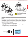
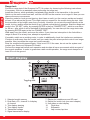
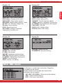
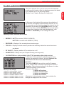
X-8N 4 channel HoTT radio control Order no.: S1018 2014/05/13 GRAUPNER/SJ GmbH. Henriettenstr.96, KG D-73230 KIRCHHEIM/TECK GERMANY English Manual Table of contents English Table of contents................................................................... 2 PUMPING menu.................................................................. 29 Foreword............................................................................... 3 START menu....................................................................... 29 Intended use.......................................................................... 3 P/MIX menu......................................................................... 30 Technical data....................................................................... 3 HW SET menu..................................................................... 30 Delivered items...................................................................... 4 SW FUN menu.................................................................... 31 Key to the Symbols............................................................... 5 S/MODE menu.................................................................... 33 Safety notes.......................................................................... 5 SERVO menu...................................................................... 35 Information on handling batteries.......................................... 6 AUX menu........................................................................... 35 General operating instructions.............................................. 8 SYSTEM menu.................................................................... 35 Manufacturer‘s declaration on behalf of GRAUPNER/SJ GmbH.................................................................................. 12 TELEMETRY MENU........................................................... 36 Operating elements............................................................. 13 First use............................................................................... 13 Adjusting the neutralization springs..................................... 14 Adjusting the position of the steering wheel........................ 14 Telemetry display................................................................. 38 Hidden mode....................................................................... 38 Firmware update transmitter............................................... 39 Operating receiver GR-8..................................................... 40 Converting the steering wheel for left-handers.................... 14 Connection example for engine-powered and electric-powered models..................................................... 42 Binding and range test........................................................ 15 Firmware update receiver.................................................... 43 Start display......................................................................... 16 Notes................................................................................... 44 Layout of switches and buttons........................................... 17 Notes................................................................................... 45 Button functions................................................................... 18 Notes................................................................................... 46 Main menu........................................................................... 18 Recommended accessories................................................ 46 Mod. SEL menu................................................................... 19 Environmental protection notes........................................... 46 MOD NAME menu............................................................... 20 Declaration of conformity..................................................... 47 MOD COPY menu............................................................... 20 Warranty.............................................................................. 48 RF SET menu...................................................................... 21 REVERSE menu................................................................. 22 E.P.A menu.......................................................................... 22 DR/EXPO menu.................................................................. 22 TRIM menu.......................................................................... 24 Although we have carefully checked the information contained in these instructions and checked that it is correct, we can accept no liability of any kind for mistakes, incomplete information and printing errors. Graupner/SJ reserves the right to alter the characteristics and features of the software and hardware at any time and without prior notification. B.R.A. menu (ATL).............................................................. 24 TH RESP menu................................................................... 25 TIMER menu....................................................................... 25 S/SPEED menu................................................................... 27 FAIL SAFE menu................................................................. 27 A.B.S. menu........................................................................ 28 IDLE UP menu..................................................................... 28 2 ! Attention! You must read these instructions in full before using the radio control for the first time. Please comply with the instructions on disposal and environmental protection on page 44 Innovation & Technology Foreword Intended use This radio control system must only be used for the operation of unmanned models. Any other use is not permitted. Ergonomically and technically modern 8 function radio control system in 2.4 GHz HoTT technology for ambitious and professional RC car and speedboat drivers. With its consistent technical optimization, the device offers an advanced operating and functional comfort in its class. Highest operational reliability through modern pulse processing by a micro computer. • Steering wheel mountable for right- and left-handers. • 2.4 GHz HoTT (HOPPING TELEMETRY TRANSMISSION) Colt transmitter • 35 channel FHSS HoTT system • Switches and rotary controls are easily accessible • Servo reverse function • Dual Rate/ Expo menu • Servo speed • and much more ... Note! English To enable you to make full use of all the features of your new radio control, read the following description carefully and in full prior to using the radio control for the first time. In particular, please observe the warning and safety notices. These instructions must be kept in a safe place, and it is imperative to hand them over to any subsequent user of the radio control. Receiver power supply For the power supply of the receiver, batteries of various technologies and capacities are selectable, see section "Installation of the receiver system" on pages 8 - 11. When using digital servos, we recommend using a rechargeable battery with 5 cells (6 V) of sufficient capacity or a BEC system* of adequate power. When using both, analog and digital servos, it is imperative to observe the respective maximum permitted operating voltage. For safety reasons, do never use battery boxes or dry cell batteries. Check the condition of the rechargeable batteries at regular intervals. Do not wait until the servos become noticeably slower, before charging the batteries. Notice: A general survey of the rechargeable batteries, chargers and measuring devices for checking the power sources can be found in the GRAUPNER main catalogue FS or on the Internet at www.graupner.de. Technical data Receiver GR-8: Transmitter X-8N: Operating voltage 3.4...6 V Operating voltage 3.6...8.4 V Frequency 2,400...2,4835 MHz Frequency 2,400...2,4835 MHz Total weight approx. 530 g Modulation FHSS Modulation FHSS Range approx. 500 m Range approx. 500 m Steering function 4 Steering function 4 Charging rate 80 mA Charging rate 210 mA Temperature range -10 ... +55 °C Temperature range -10 ... +55 °C Aerial length 110 mm Aerial length 80 mm Dimensions approx. 30 x 21 x 14.3 mm Dimensions approx. 240 x 172 x 140 mm Total weight approx. 6.9 g 3 Delivered items English The requirements placed on rechargeable batteries vary depending on how they are used. This in turn means that various types of connectors are required. Please note that connections, names and polarities may vary from one manufacturer to another. You must therefore only ever use compatible original connectors of the same type. You must also only use original charging cables with a sufficient wire cross-section. The set includes: X-8N HoTT transmitter GR-8 receiver NiMh battery 2000 mAh/4 cells SD card USB cable Charger Trim button insert for left-hander conversion • Manual • • • • • • • 4 Innovation & Technology Key to the Symbols This symbol alerts you to the following notes which the user must observe. Neglecting this information may have an adverse effect on the system’s proper function and the safety of the operator. Warning! This symbol alerts you to prohibited actions which the user must always observe. Neglecting these warnings may have an adverse effect on the system’s proper function and the safety of the operator. English ! Attention! Care and maintenance! This symbol calls attention to notices about care of the model which must absolutely be observed to ensure its long service life. Note! This symbol alerts the user to information which must always be observed in order to ensure the safe operation of the device. Tip! This symbol alerts you to hints and tips during the model’s construction which help to avoid problems and potential damage, and provide information on solving possible problems. Disposal notes This symbol calls attention to information regarding specific materials or products, which must be observed when disposing of these items. Safety notes ! ! ! ! Attention! Protect all equipment from dust, dirt, moisture and other foreign parts. Do not expose this equipment to vibration and excessive heat or cold. The remote control operation may be carried out only at "normal" temperatures, ie in the range of -10 ° C to +55 ° C. Attention! Avoid shock and pressure load. Check the equipment regularly for damage to enclosures and cables. Do not use equipments that is damaged or has become wet, even if they are dry again! Attention! The transmitter is intended exclusively for use in radio-controlled models. Any other usage is prohibited, and may result in damage to the receiver or model, and serious personal injury. We grant no guarantee and accept no liability for any type of use outside the stipulated range. Attention! Technical problems in electrical and mechanical systems can lead to an unexpected start an engine and / or loose parts that can not only greatly hurt you! 5 ! English ! ! ! ! ! ! ! Attention! Shorts of any kind are to be avoided! By short-circuiting not only parts of the remote control may be destroyed, but, depending on the circumstances and the energy content of the batteries beyond acute combustion to explosion. Attention! All parts driven by a motor such as air and boat propellers, helicopter rotors, open gears, etc. pose a constant risk of injury; they should never be touched! A rapidly spinning propeller, for example, can cut off a finger! Make sure that any object with powered parts may come in contact! Attention! If the drive battery is connected or the engine is running, keep yourself never in the danger area of the drive! Attention! During the programming process you must bear in mind that an internal combustion engine or electric motor could unexpectedly burst into life at any time. Attention! The transmitter may only be operated with accessories which we recommend as otherwise functionality cannot be guaranteed. Attention! When deploying the cables ensure that they are not under tension, not tightly bent (kinked) or fractured. Avoid sharp edges which could damage cable insulation. Attention! Ensure that all plug-in connections are firmly seated. Do not pull on the wires when disconnecting plugs and sockets. Attention! It is not permissible to carry out modifications of any kind to the receiver. Any changes invalidate product approval, and you forfeit any insurance protection. In this case, send the device to the appropriate Graupner service, see page 46 Information on handling batteries Attention! ! 6 Charging single Ni-Cd or Ni-MH cells, and packs consisting of 1 ... 4 cells, presents the automatic charge termination circuit with a difficult task. The voltage peak is quite small in such cases, and it cannot be guaranteed that the cut-off circuit will work reliably. In such conditions the automatic circuit may not be triggered, or may not terminate the charge at the correct time. For this reason it is important to carry out a series of monitored test charge processes with your packs in order to establish whether the charge process is terminated reliably. Fire / explosion hazard! Innovation & Technology ! ! ! ! ! ! ! ! ! ! Overcharging and deep-discharge processes cause irreparable damage to the cells, permanently impair the performance of the battery and reduce its capacity. Attention! Never store batteries for extended periods when they are uncharged, empty or partially charged. Charge the batteries to their specified storage capacity before placing them in storage and check their charge level from time to time. Attention! English ! Attention! When buying batteries, make sure they are of good quality. Start by charging new batteries at low rates, and work up gradually towards higher currents. Attention! Only charge batteries shortly before use, as they are then able to deliver their best performance. Attention! Do not solder directly onto the batteries – the temperatures which occur during soldering can damage the seals and safety valves of the cells. This would cause the battery to lose electrolyte or dry out, and some of its performance would be lost. Attention! Overcharging damages battery capacity. Therefore, do not charge the battery if it is hot or has already been charged. Attention! Charging and discharging any battery at a high current shortens its life expectancy. Do not exceed the values specified by the manufacturer. Attention! Only charge batteries shortly before use, as they are then able to deliver their best performance. Attention! Protect batteries from vibration and do not subject them to mechanical stress. Attention! Batteries can generate explosive gas (hydrogen) when charging and during operation. It is therefore important to provide adequate ventilation. Attention! Do not allow batteries to come into contact with water – explosion hazard! 7 ! English ! ! ! ! ! Attention! Never short-circuit battery contacts – explosion hazard! Attention! Batteries can explode or catch fire if they are defective. We therefore recommend charging the batteries in a LiPo safety case (order no. 8370 or 8371). Attention! Do not open batteries – risk of chemical burns. Achtung! NiCd- oder NiMH-Akkupacks lassen sich am besten formieren indem zuerst alle Zellen einzeln und separat entladen werden und anschließend der gesamte Akkupack aufgeladen wird. Das Entladen erfolgt mit dem Ladegerät (Zelle für Zelle). Attention! Do not be surprised if your battery packs do not charge as quickly and their level of performance is not as high in winter as in summer. The ability of a cold cell to accept and store charge is much lower than that of a warm one. Attention! Information on the German Batteries Act: exhausted batteries are regarded as hazardous waste and must not be disposed of as domestic waste. The specialist retailer where you bought your batteries will have battery recycling containers which you can use to dispose of them. The retailer is obliged by law to accept exhausted batteries for disposal. General operating instructions Method for Installation of Receiver The receiver is to be installed with a foam rubber cushion to afford protection against jarring, in aircraft models behind a strong rib and in a car or ship model in a place where it is protected against dust and spray water. The receiver may not be mounted in direct contact with the hull or chassis as this would allow motor vibrations and/or landing jolts to be transferred directly to the receiver. When a receiver system is installed in a model with a combustion motor, all receiver parts should be installed so as to prevent exhaust gases and oil residues from infiltrating. This especially applies to the ON/ OFF switch, which is usually built into the model’s outside skin. Position the receiver such that connecting cables to the servos and the power supply are routed with a bit of slack and that the receiver’s antenna is at least 5 cm away from any large metal parts or wiring other than those proceeding from the receiver. In addition to steel, this also applies to carbon fiber parts, servos, electric motors, fuel pumps, any kind of cable and similar items. Optimally the receiver should be placed at a readily accessible location that is well away from all other equipment. Under no circumstances may a servo cable be wrapped around the antenna or routed close to it. Ensure that cables near the antenna cannot move about during flight. 8 Routing the receiver’s antenna The receiver and the antennas must be positioned as far away as possible from any drive components. If the model’s hull is made of carbon fiber material, the ends of the antennas should always extend outside of the hull. The orientation of antennas is not critical. Nevertheless, a vertical (upright) installation of the receiver’s antenna(s) is advantageous. English Innovation & Technology Servo installation Always mount servos with the rubber vibration-damper parts provided. This is the only way of ensuring some protection against excessively strong vibrations. Installing linkage Linkage must be installed so as to ensure unhindered and smooth movement. It is particularly important that all rudder levers are able to move to their full limits and are not blocked mechanically. In order to be able to stop a running motor at any time, the linkage must be set to ensure that the carburetor tap is completely closed when the joystick and trim lever are brought into their end idle positions. Pay attention that no metal parts rub against one another, e.g. as a result of moving the rudder, of vibration, rotating parts etc. Metal-to-metal contact causes ‘static’ which can interfere with the correct operation of the receiver. Transmitter antenna orientation The patch antenna is integrated in the rectangular front panel of the transmitter. This means that ‘aiming’ the transmitter at the model will have a positive effect on reception. However, when two or more pilots using 2.4 GHz remote control systems are within 5 m of one another this can lead to return channel overdrive which, in turn, will trigger a range warning much too soon. Increase your distance between one another until the range warning ceases. Pre-start checks Before switching the receiver on, ensure that the throttle control is in the Stop/Idle position. Always switch the transmitter on first and then the receiver. Always switch the receiver off first and then the transmitter. WARNING: If this sequence is not maintained, and the receiver is still switched on when the corresponding transmitter is switched to the ‘OFF’ position, then the receiver may respond to other transmitters or general radio frequency noise. This can cause the model to execute uncontrolled operations that may cause personal injuries and/or property damage. ! 9 English Range test Perform checks for proper operation and range before any use. Secure the model adequately in place and ensure that no one is in front of the model. Perform a complete functional test on the ground and execute a complete simulated flight to rule out the possibility of system faults or problems with the model’s programming. You must refer to the instructions in the manual of the transmitter. Do not operate your model, ie when flying or driving, without transmitter or receiver antenna. Ensure a tight fit of the antenna. Monitoring transmitter and receiver batteries You must stop running the model to replace or recharge the transmitter’s battery no later than when, as a result of the drop in battery voltage, the red status LED flashes and an acoustic warning sounds. Check the status of batteries regularly, particularly the receiver’s battery. Do not wait for the movements of controlled mechanisms to become noticeably slower. Replace expended batteries before they cause problems. Always follow the battery manufacturer’s charging instructions are adhere exactly to charging times. Never leave batteries unattended while charging. Use your charger only in rooms equipped with a smoke detector for protection. Warning: Never attempt to charge dry cell (non-rechargeable) batteries (risk of explosion). All rechargeable batteries must be charged before every use. To avoid short circuiting, first connect the charger cable’s banana plugs with correct polarity to the charger and then plug the charger cables into the sockets for the transmitter and receiver batteries. Disconnect all batteries from the model when it is not to be used for an extended period of time. Never use defective batteries, damaged batteries or different types of battery cells in combination. Do not use combinations of old and new batteries or batteries from different manufacturers. Capacity and operating time The rule that capacity is reduced with every successive recharging applies to all batteries. Internal resistance increases at low temperatures, further reducing capacity. As a consequence, the battery’s ability to supply current and retain its voltage is reduced. Frequent charging or the use of battery maintenance programs can also result in gradual loss of battery capacity. Battery capacity should therefore be checked at regular intervals of not more than every six months and the batteries replaced if performance is found to be significantly deficient. Purchase only genuine Graupner batteries! Interference suppression for electric motors With all conventional electric motors, sparks are generated between the collector and brushes. Depending on the type of motor involved, this may interfere more or less with the functioning of the remote control system. The electric motors of a properly built system should therefore include interference suppression. For electric drive models it is particularly important that every one of its motors is equipped with proper interference suppression. Interference filters largely suppress such disturbances and should always be installed. Follow the specific recommendations included in the motor’s operating and installation instructions. For further details about interference filters, refer to the Graupner RC main catalog or on the web at www.graupner.de. Servo interference filters for extension cables Order No. 1040 The servo interference filter is necessary when an extended-length servo cable is used. This filter is attached directly to the receiver output. In critical cases a second filter can be attached to the servo. Using electronic speed controllers Choosing the right electronic speed controller largely depends on the power of the motor used. In order to prevent an overload or damage to the speed controller, its current rating should be at least half of the maximum locked-rotor current rating of the motor. Special caution is necessary in the case of motors referred to as ‘tuning motors’. Due to the small number of coil windings, such motors can draw a multiple of their rated current in a 10 locked-rotor condition, leading to irreparable damage to the speed controller. Electric ignition systems Combustion engine ignition systems also produce interference that can adversely affect remote control functioning. Always supply power to an electric ignition system from a separate, dedicated battery. Use only interference-suppressed spark plugs, spark plug connectors and shielded ignition cables. Mount the receiver at an adequate distnce from ignition system components. Static charges Warning: Lightening results in magnetic shock waves that interfere with the functioning of a remote control system – even if the storm is miles away. Therefore … … stop flying right away if a storm is approaching. Static charges gathered via the antenna also represent a lethal hazard. Please observe the following: • In order to fulfill FCC RF emission requirements for mobile transmitters, a distance of at least 20 cm must be maintained between the system antenna and any persons while this system is being operated. Operation of this system at a smaller distance is therefore not recommended. • To avoid disturbance caused by the electrical properties and emission characteristics of other transmitters, maintain a distance at least 20 cm from other transmitters. • To operate the remote control system, the transmitter unit requires the correct program setting for the given country. This is necessary for compliance with various regulations such as FCC, ETSI, CE etc. Follow the specific instructions on this provided with the transmitter and receiver. • Prior to every flight, perform a complete functional test, range test and execute a complete simulated flight in order to rule out any possibility of system faults or problems with the model’s programming. • Never program the transmitter or receiver while the model is being operated. ! English Innovation & Technology Components and accessories As manufacturer of this equipment, Graupner/SJ GmbH recommends only components and accessories which have been tested and approved by Graupner for suitability, functioning and safety. Where this recommendation is followed, Graupner/SJ retains responsibility for the product. Graupner/SJ cannot accept any liability for non-approved parts or accessories supplied by other manufacturers and cannot assess every individual third party product as to suitability of use without safety risk. Care and maintenance Care instruction! The transmitter is entirely maintenance-free and therefore requires no servicing of any kind. However, it is in your own interests to protect the charger from dust, dirt and moisture. Care instruction! To clean the transmitter, disconnect it from the battery pack and gently wipe it clean with a dry cloth only (do not use any cleaning agents). 11 Manufacturer‘s declaration on behalf of GRAUPNER/SJ GmbH Contents of the manufacturer’s declaration: English If material defects or manufacturing faults should arise in a product distributed by us in the Federal Republic of Germany and purchased by a consumer (§ 13 BGB), we, Graupner/SJ GmbH D-73230 Kirchheim/Teck, Germany, acknowledge the obligation to correct those defects within the limitations described below. The consumer is not entitled to exploit this manufacturer’s declaration if the failure in the usability of the product is due to natural wear, use under competition conditions, incompetent or improper use (including incorrect installation) or external influences. This manufacturer’s declaration does not affect the consumer’s legal or contractual rights regarding defects arising from the purchase contract between the consumer and the vendor (dealer). Extent of the guarantee If a claim is made under guarantee, we undertake at our discretion to repair or replace the defective goods. We will not consider supplementary claims, especially for reimbursement of costs relating to the defect (e.g. installation / removal costs) and compensation for consequent damages unless they are allowed by statute. This does not affect claims based on legal regulations, especially according to product liability law. Guarantee requirements The purchaser is required to make the guarantee claim in writing, and must enclose original proof of purchase (e.g. invoice, receipt, delivery note) and this guarantee card. He must send the defective goods to us at his own cost, using the following address: Graupner/SJ GmbH, Service Department, Henriettenstr.96, D 73230 Kirchheim/Teck, Germany Service Department: tel. [0049] 7021-722130 The purchaser should state the material defect or manufacturing fault, or the symptoms of the fault, in as accurate a manner as possible, so that we can check if our guarantee obligation is applicable. The goods are transported from the consumer to us and from us to the consumer at the risk of the consumer. Duration of validity This declaration only applies to claims made to us during the claim period as stated in this declaration. The claim period is 24 months from the date of purchase of the product by the consumer from a dealer in the Federal Republic of Germany (date of purchase). If a defect arises after the end of the claim period, or if the evidence or documents required according to this declaration in order to make the claim valid are not presented until after this period, then the consumer forfeits any rights or claims from this declaration. Limitation by lapse of time If we do not acknowledge the validity of a claim based on this declaration within the claim period, all claims based on this declaration are barred by the statute of limitations after six months from the time of implementation; however, this cannot occur before the end of the claim period. Applicable law This declaration, and the claims, rights and obligations arising from it, are based exclusively on the pertinent German Law, without the norms of international private law, and excluding UN retail law. 12 Innovation & Technology Operating elements ③ ① ⑤ English ④ ② ⑥ 1. Display/control panel3. Aerial 2. Steering wheel4. Data socket 5. Charging port 6. Throttle/brake lever First use Battery connection • Use NiCd/NiMH batteries of size AA. (or a LiPo battery with 1 cell) • Remove the cover and connect the battery or the battery holder, while observing the correct polarity. Shut the cover and ensure the cover sits properly. • If a voltage warning has been triggered, charge the batteries. • Correctly set the battery type and the battery warning threshold in accordance with the used battery. • You can also charge batteries in the transmitter. To do so, use the charger depending on the type of battery (NiMh or LiPo), which is optionally available. The charging current must not be above 1 A, since this would destroy the transmitter and could cause a fire. Observe the correct polarity of the charging socket (see figure below). Polarity of the charging socket 13 Adjusting the neutralization springs English The adjusting screw for adjusting the neutralization spring for the steering wheel is located in the housing below the wheel. By turning the screw left or right, the reset force is increased or decreased. The adjusting screw for adjusting the neutralization spring for the throttle lever is located in the housing at the throttle lever. By turning the screw left or right, the reset force is increased or decreased. Adjusting the position of the steering wheel You can adjust the position of the steering wheel forward or backward. To do so, remove the cover with the HoTT logo above the steering wheel. Then, loosen the two screws and place the steering wheel in its new position. Now, you retighten the two screws. Converting the steering wheel for left-handers The entire steering wheel can be converted to the left side for operation by left-handers. To do so, you have to change the trim button insert, lying underneath. For left-hander operation, use the trim button insert, included in the supply. 1. Remove the HoTT logo cover (see following figure) 2. Now, unscrew the steering wheel 3. Unplug the cable of the steering wheel 4. Mount the steering wheel on the left side and replug the cable. Mount the trim button insert, included in the supply. 5. Tighten the steering wheel and refit the HoTT logo cover. 14 Innovation & Technology 2. English 1. 5. 3. 4. ! Attention! After the conversion, check all functions of steering wheel and trim button, before you operate a model again! Binding and range test Binding: In order to be able to establish a connection to the transmitter, the Graupner-HoTT receiver has first to be "bound" to "its own" Graupner-HoTT transmitter. This procedure is called "binding". However, "binding" is necessary only once per receiver-transmitter combination, and has already been done at the factory with the devices that are delivered in one set, so you have to perform the "binding" only with further receivers (and – can repeat it any time – e. g. after a transmitter change). To do so, perform the following steps: • Switch on the receiver and put it in binding mode, by pressing and holding the binding button for 3 sec. (green and red LED on the receiver are flashing) • Trigger the binding in the menu "RF SET", by pressing the Enter button in the line "Receiver" • If the red LED of the receiver goes out within about 10 seconds and the green LED is illuminated, the binding process has been completed successfully. • Your transmitter/receiver combination is now ready for operation. If the red LED is still lit, the "binding" failed. In this case, repeat the whole procedure. Receiver Binding button Transmitter display RF SET RECEIVER : : TEL.RCV RF ON/OFF : RANGE TEST : CH FUNKTION : R 04 1 ON 99s ==> Binding display in transmitter display 15 Range test: English Perform a range test of the Graupner HoTT 2.4 system, by observing the following instructions. If necessary, look for an assistant when performing the range test. Install the receiver, which preferably has already been bound to the transmitter, in the model. Switch on the radio control and wait, until the red LED on the receiver is no longer lit. Now you can observe the servo movements. Place the model on level ground (paving, short lawn or earth), so the receiver aerials are located at least 15 cm above the ground. This might require a support for the model during the test. Hold the transmitter at hip-height, away from your body. However, do not point the aerial directly at the model, but turn and/or angle the aerial tip so it stands vertical during operation. Start the range test mode in the "RF SET" menu, by pressing ENTER in the line "RANGE TEST", which is now active for 99 sec., after which it will be switched off automatically. You can also quit the range test mode by pressing ENTER again in the line "RANGE TEST". Walk away from the model, and move the sticks. If you detect an interruption in the link within a range of about 50 m at any time, attempt to reproduce it. If possible, switch on an existing motor, in order to additionally check the interference resistance. Continue to walk away from the model, until you reach the point where perfect control is no longer possible. Now, terminate the range test mode manually. Now, the model should respond again. If this is not 100 % the case, do not use the system and contact your Service at Graupner/SJ GmbH. Perform the range test before each operation and simulate all servo movements which are part of the normal operation. In order to guarantee a safe model operation, the range must always be at least 50 m on the ground. Start display 7 1 6 9 4 2 3 UP 8 5 Toggling with: 10 11 12 1.Selected model memory 2.Dual-Rate, ATL, channel 3+4 display of channel 3.Trim display steering 4.Trim display throttle 5.Transmitter voltage 6.Signal transmission display 16 7.Display for headphones and SD card 8.Display for button lock (see next chapter) 9.User name or alert display 10. Flight time 11. Stopwatch 12. Lap counter, lap time INNOVATION & TECHNOLOGY English Layout of switches and buttons TR4/TR5/PS2 Throttle lever PS1/Dial TR1/TR2/TR3 TR4/TR5/PS2 Steering wheel 17 Button functions English EN ER T FUNC = Main menu, go to main menu ESC = go to previous menu ENT = Select INC, DEC, DOWN, UP = go to various menus or change values Button combinations for menu quick access FUNC+ESC = Display servo bar INC+DEC = Resets changes in the settings UP+DOWN = Hidden mode INC+DEC+ENTER = Activates or deactivates the button lock (press and hold for 2 sec.) Transmitter LED status information Red LED (Power): Transmitter switched on Blue LED (RF): HF switched on Warning: red and blue LED flash alternately Function warning: red LED flashes Range test: blue LED flashes Main menu The main menu has 4 display pages. With the FUNC button, you can browse between the pages. 18 Display 1/4 Display 2/4 MOD. SEL: Select model memory MOD Name: Change model name MOD COPY: Copy model memory MOD RES: Delete model memory / reset RF-SET: HF / Binding / Range test Reverse: Servo reverse E.P.A: Servo travel limit DR / EXPO: Setting of dual rate, exponential, throttle curve TRIM: TRIM, Sub-Trim B.R.A: Brake setting (ATL) TH RESP: Throttle response speed TIMER: Lap timer, stopwatch, lap time list S / SPEED: Steering/throttle servo speed FAIL SAFE: Fail safe A.B.S: A.B.S. Brake setting IDLE UP: Motor idle setting Display 3/4 Display 4/4 PUMPING: Pumping function START: Start function P / MIX: Free mixers HW SET: Hardware switch settings SW FUN: Assigning switch functions S / MODE: Crawler,Tank, Boat menu SERVO: Servo settings AUX: Channel 3.4 setting SYSTEM: System settings TELEMETRY: Telemetry setting English Innovation & Technology Mod. SEL menu In this menu, a model can be selected. Altogether 25 models can be saved. Saved models can be loaded, and new model memories can be created. • INC, DEC, UP, DOWN = Move around the display • ENT = Select model memory • ESC = Quit menu (step back) 19 MOD NAME menu English In this menu, you can enter model and user names. The keypad appears as shown in the figure below if "MODEL NAME" or USER NAME" are selected. You can enter 10 characters for the model name and 15 characters for the user name. MOD COPY menu In this menu, model memories can be copied to SD card or loaded from SD card. COMPLETE This sign appears when the copy process has been completed. • SOURCE: Select the model memory to be copied • TARGET: Select the memory location and press ENT, in order to copy the source memory location (Source) to the target memory location (Target) • Export function: Copy source memory location to SD card • Import function: Transfer a copy of the model memory from SD card to the control. MOD RES menu In this menu, you can initialize or delete saved settings. • RESET = initializes all functions, except the model designation. • DELETE = deletes the entire model memory (only if the model is currently not in use) 20 Innovation & Technology This menu appears if no receiver is bound to the selected model memory location. After the binding process, the whole menu appears as on the following display. (Binding - see Chapter: Binding and range test) English RF SET menu In this menu, the binding of the receiver, the selection of the receiver, the display of the telemetry receiver, HF on/ off, range test and the selection signal per channel can be performed. By pressing the UP/DOWN buttons, you can move in the menu, with the ENTER button you can select the menu item (selection has a dark background), with INC/DEC or UP/DOWN you can change the value. Meaning of the individual menu items • MODULE = HoTT for receiver (GR-4/12/16/24/32) HoTT V2 for receiver with SUMD-V1 (GR-8) • RECEIVER = Display of the currently bound receiver type • TEL.RCV = D isplay of which receiver provides the telemetry data when several receivers are bound • RF ON/OFF = Display, whether HF is switched on or off • RANGE TEST = Range test (see Chapter: Binding and range test) • CH FUNCTION ==> (only available in HoTT V2 operation with suited receiver) In this menu, the properties for adjusting to the servo, used by the respective channel, are set. (Observe the information from the servo manufacturer) Attention: The setting SUMD-V2 can only be used for Graupner servos, sensors and controllers supporting this function! Attention: Follow the instructions on the screen, in order to save the settings in the receiver! Proceed in this order! Meaning of the settings: 1. Switch off receiver USR1m50 : ULTRA SIGNAL 1.5 msec 2. Switch off transmitter FSR3m00 : FAST SIGNAL 3.0msec 3. Switch on transmitter SUMD-V2 : FAST SIGNAL BUS 3.0msec NSR6m00 : NORMAL SIGNAL 6.0msec 4. Switch on receiver NSR12m0 : NORMAL SIGNAL 12.0msec Afterwards, in the telemetry menu, check whether the NSR24m0 : NORMAL SIGNAL 24.0msec settings are displayed in the receiver. 21 REVERSE menu English In this menu, the direction of the servo rotation for the respective channel is set. Select the channel on the left side, by pressing the UP and DOWN buttons. With the ENTER button, you toggle between NOR (Normal) and REV (Reverse) and thus change the direction of the servo's rotation. E.P.A menu This function sets the maximum servo travel of the servo per channel. The left and right deflection can be set separately in the range from 0 - 150 %. By pressing the UP/DOWN buttons, you can move in the menu, with the ENTER button you can select the menu item (selection has a dark background), with INC/DEC or UP/DOWN you can change the value. DR/EXPO menu In this menu, you can set the DR (Dual Rate) and EXPO (Exponential) function for the steering and throttle channel. To do so, select in the CH line: ST for steering channel, and TH for throttle channel. Steering channel setting: D/R: 0 - 100% Setting the Dual Rate function EXP: -100% to + 100% Setting the Exponential function MODE: Here, the switch is shown (e.g. PS2) which has been assigned to the function ST DR/ EXPO in the SW FUN menu. The switch can be used to activate or deactivate the Dual Rate function. (Only one pressure switch can be assigned) SW: Here, the switch is shown (e.g. TR4) which has been assigned to the function "ST DUAL" or "ST EXPO" in the SW FUN menu. Changes in the settings are directly shown on the display. (A trim button or a rotary control can be assigned) 22 Innovation & Technology Throttle channel settings: In this menu, a throttle curve with 4 points can be established. Curve: ON - OFF activates or deactivates the throttle curve POINT : N - H = Neutral - Full throttle 0% : Display of the position of the 4 points on the curve SW: Here, the switch is shown which has been assigned to the function in the SW FUN menu. The switch can be used to activate or deactivate the Dual Rate function. (Only one pressure switch or trim button can be assigned) English 0% -> 0% : display of the current position of the throttle lever in percent If you press ENTER at the position at which you want to alter the curve, a point is created, and the curve value can be changed at the respective position. A maximum of 4 points can be set. If you have highlighted the field 0% in the POINT line and then press the INC button, Trim point appears in the 2nd line. Here, you can use the INC/DEC button, to select the point on the curve to be changed and move it with the UP/DOWN button. Pressing the INC/DEC button simultaneously = deletes the point. In the SW FUN menu, the values for shifting the points can be assigned to trim buttons, by assigning the functions TH CP2 - TH CP6 to a trim button. If you have selected "ON" in the CURVE line, the throttle curve will be smoothed. If you have selected "OFF" in the CURVE line, the throttle curve acts directly. If you have highlighted the field in the POINT line and then 2x press the INC button, Trim X-axis appears in the 2nd line. If you move to a point with the throttle lever, you can move the point up and down with UP/DOWN and to the left and right with INC/DEC. In the SW FUN menu, the values for shifting the points can be assigned to trim buttons, by assigning the functions TH CP2 - TH CP6 to a trim button. 23 0% in the POINT line If you have highlighted the field and then 3x press the INC button, Trim offset appears in the 2nd line. Using the UP/DOWN buttons you can move the entire curve up or down. English TRIM menu In this menu, the trimming for each channel can be performed. (By pressing the DOWN button after 3CH, 4CH will be visible, which is usually outside the display range.) SW shows the buttons assigned for trimming in the SW FUN menu. ST: RT - LT (+ right or - left deflection) TH: FW - BW (+ forward or - backward deflection) MAIN: With this trim function, only the centre of the servo will be moved, the full deflections remain unchanged. SUB: With this trim function, the entire servo travel is moved, i.e. the position of the full deflections also changes. SW: Here, the switch is shown (e.g. TR1) which has been assigned to the function "ST SUBT" or "TH TRIM" in the SW FUN menu. Changes in the settings are directly shown on the display. (A trim button or a rotary control can be assigned) B.R.A. menu (ATL) In this menu, the travel distribution for the brake travel and the throttle travel in the throttle channel can be set. Also, the size of the brake range can be defined. RATE: 50:50 - 70:30 with the setting 70:30, the servo centre is moved. (Default setting: 50:50) B.R.A.: 0 - 100% Here, the size of the brake range is defined. 24 Innovation & Technology In this menu, one point each can be set in the throttle travel and in the brake travel, from which the control starts. When operating the throttle lever in the direction of throttle or brake, the servo immediately jumps to this point, from where the control starts. (e.g. in order to compensate backlash of the throttle linkage or throttle response weakness in the lower range) English TH RESP menu FW: 0 - 100% BK: 0 - 100% SW: Here, the switch is shown (e.g. TR1) which has been assigned to e.g. the function "RESP FW" or "RESP BK" in the SW FUN menu. Changes in the settings are directly shown on the display. (A trim button or rotary control can be assigned) TIMER menu 25 English The timer function is started or stopped by assigning switches in the SW FUN menu. The function is executed as follows: • Menu: LAP TIMER, FINISH is shown inversed • By pressing INC/DEC simultaneously, the timer is set in standby, the FINISH display changes to READY, the timer is started by accelerating • Pressing switch for "LAP TIMER" = 1x = intermediate stop of the timer function, pressing 2x = finishing the timer (e.g. PS1) • Switch for "LAP STOP" = Stopping the lap time LAP TIMER: - FINISH Overall Timer: Total travel time - TG / Timer: Target time - ALARM: Alarm time - P / ALARM: Pre-registration of alarm time - AV / TIME: Average travel time LAP RECORD: - Maximum lap number: 99 (99m59s99 can be saved per lap) - BEST LAP: Display of fastest lap - AVER LAP: Display of average time of all laps UP TIMER: Up-counting stopwatch Starting and stopping the timer by assigning a button in the "SW FUN" menu - Alarm - Setting the alarm time 0 - 99 minutes - P/Alarm - Warning before the alarm time has elapsed 0 - 59 sec. DOWN TIMER: 26 Down-counting stopwatch Starting and stopping the timer by assigning a button in the "SW FUN" menu - Alarm - Setting the alarm time 0 - 99 minutes - P/Alarm - Warning before the alarm time has elapsed 0 - 59 sec. - SET TIMER: Setting the time, from which it is counted up or down Innovation & Technology In this menu, the servo speed for the steering and throttle servo can be set. For the steering servo, you can set the speed for left and right and for forward and return travel separately. For the throttle servo, a point can be set at which the speed is set in two steps. English S/SPEED menu STEERING: - TURN: Speed servo forward path - RETURN: Speed servo return path - SW: Display of switches which can be assigned to this function in the "SW FUN" menu (see list in Chapter "SW FUN menu") THROTTLE: - THROTTLE: Setting of speed for both ranges HIGH and NEUTRAL - POINT: Setting of switchover point of both ranges - SW: Display of switches which can be assigned to this function in the "SW FUN" menu (see list in Chapter "SW FUN menu") FAIL SAFE menu In this menu, you can make the Fail Safe settings individually for each channel. This function sets the servo of the respective channel into a predefined position, in case of a signal loss of the receiver. For instance, the throttle servo of an enginepowered model can, in this case, be set to idle (of an electricpowered model to motor Off), so the model does not move on without control. FREE: No Fail Safe function HOLD: The servo is held on the last position POSITION: The servo is moved to a defined position Setting the position: Select POSITION at the respective channel, confirm with ENTER, and a percentage display appears to the right of the channel. Then, switch to the right to the percentage display and confirm with ENTER, now you set the desired position at the servo by operating the corresponding encoder. Confirm with ENTER, and the percentage display shows the position of the servo. DELAY: Here, you set the delay time, until the response of the Fail Safe in case of a signal loss of the receiver. (50 ms, 100 ms, 250 ms, 500 ms, 750 ms, 1 s) Attention: Save the settings by pressing the FUNC button in the receiver!! is shown for confirmation. 27 A.B.S. menu English In this menu, the A.B.S. function can be set. A.B.S. enables a better braking response, since the brake is actuated in pulses. ACT: INH = function OFF, ACT= function ON SW: Display of switches which can be assigned to this function in the "SW FUN" menu (see list in Chapter "SW FUN menu") ACT: ACT = A.B.S. ON, INH = A.B.S. OFF DUTY: Ratio between pulse and pulse pause (see sketch below) T/P: Here, the point on the brake lever path is set, from which the A.B.S. will become active MOV: Setting the pulse height (see sketch below) CYC: Setting the pulse length (see sketch below) DELAY: Here, you set the delay time, until the response of the A.B.S. (0 - 1 s) DUTY MOVE CYC IDLE UP menu In this menu, the motor start function "Idle Up" can be set. IDLE UP enables a better start of the cold combustion motor, since the throttle is held on a specific value, here. You can set this value in the POS line. After starting the motor, this function has to be deactivated again, since the throttle lever has no effect during the IDLE UP function. ACT: INH = IDLE UP function OFF, ACT = IDLE UP function ON SW: Display of switches which can be assigned to this function in the "SW FUN" menu (see list in Chapter "SW FUN menu") 28 Innovation & Technology In this menu, the "PUMPING" function can be set. PUMPING enables automatic throttle activations, e.g. during refuelling, so the motor does not overgrease or go out when in idle. You can set the strength of the throttle activation in the POS line. The waiting time between the throttle activations can be set in the DELAY line. English PUMPING menu ACT: INH = PUMPING function OFF, ACT= PUMPING function ON SW: Display of switches which can be assigned to this function in the "SW FUN" menu (see list in Chapter "SW FUN menu") START menu In this menu, automatic start function "START" can be set. The START function allows a quick start without spinning of the drive wheels, since the throttle is held on a specific value, first. You can set this value in the RATE line. This function is activated by assigning a switch. By activating this switch, the START function is set on standby. If now the throttle lever exceeds the trigger point (T/POS), the function is triggered. With TIME, the delay of the response of this function is set, when exceeding the trigger point. ACT: INH = START function OFF, ACT= START function ON SW: Display of switches which can be assigned to this function in the "SW FUN" menu (see list in Chapter "SW FUN menu") RATE TIME T/POS 29 P/MIX menu English In this menu, the 5 free mixers can be set. When selecting a mixer from the list, the following display appears, in which you can make the settings. To the right of the mixer, there is the status display, whether the mixer is switched On of Off. • • • • • ST: Selection of the source channel signal, whose rate is M set with RATE and added to the target channel (SLV). SLV: Selection of the target channel, set the mixing rate with RATE OFFSET: Centre setting of the target channel (SLV) ACT: INH = Mix function Off, ACT= Mix function On SW: Display of switches which can be assigned to this function in the SW FUN menu (see list in Chapter "SW FUN menu") HW SET menu In this menu, you can set the properties of the trim buttons, switches and rotary controls, which can be assigned a function. REV: NOR = normal switching function REV = inverse switching function T/S: Setting of the increment (only for trim buttons and rotary controls) SET: Setting the mode of operation of the switch PUSH = push button TOG = press once - on; press again - off At the throttle channel TH and at the steering channel ST, a switching function can be set here, by setting the percentage at a specific point of the control path. 30 Innovation & Technology English SW FUN menu In this menu, you can assign a function to trim buttons, switches and rotary controls. By default, some buttons and switches have already been assigned functions, which can be assigned again as all the others, as follows: After selecting a switch with the UP/DOWN buttons, press Enter, and the menu with the possible functions for this switch appears. Here you can select a function with the UP/DOWN and INC/DEC buttons and confirm it with ENTER. Then, the display goes back to the previous screen, where you can see the new function behind the switch. Meaning of the functions for TR1, 2, 3, 4, 5 and rotary control ST TRIM Steering trimming TH TRIM Throttle trimming 3CH TRIM Channel 3 trimming 4CH TRIM Channel 4 trimming ST Sub Trim Steering sub trimming TH Sub Trim Throttle sub trimming 3CH SUBT Channel 3 sub trimming 4CH SUBT Channel 4 sub trimming ST Dual Steering Dual Rate ATL Brake travel setting ST EXPO Steering exponential function TH CP2 Throttle curve point 2 TH CP3 Throttle curve point 3 TH CP4 Throttle curve point 4 TH CP5 Throttle curve point 5 TH CP6 Throttle curve point 6 RESP FW Throttle response point (TH RESP menu) RESP BK Brake response point (TH RESP menu) SPD ST RT Speed steering servo right forward path (S/SPEED menu) SPD ST LT Speed steering servo left forward path (S/SPEED menu) 31 English 32 SPD ST RR Speed steering servo right return path (S/SPEED menu) SPD ST LR Speed steering servo left return path (S/SPEED menu) SPD TH HG Speed throttle servo range High (S/SPEED menu) SPD TH NT Speed throttle servo range Neutral (S/SPEED menu) ABS TRG ABS activation point (ABS menu) ABS MOVE ABS pulse height (ABS menu) BRAKE 3CH Brake travel channel 3 BRAKE 4CH Brake travel channel 4 IDLE UP Throttle position (IDLE UP menu) PUMPING Strength of throttle activation (PUMPING menu) START POS Start function activation point (START menu) START RAT Start function throttle position (START menu) PMIX1 A Mixer 1, mixing rate source channel signal PMIX1 B Mixer 1, mixing rate target channel PMIX1 OFF Mixer 1 off PMIX2 A Mixer 2, mixing rate source channel signal PMIX2 B Mixer 2, mixing rate target channel PMIX2 OFF Mixer 2 off PMIX3 A Mixer 3, mixing rate source channel signal PMIX3 B Mixer 3, mixing rate target channel PMIX3 OFF Mixer 3 off PMIX4 A Mixer 4, mixing rate source channel signal PMIX4 B Mixer 4, mixing rate target channel PMIX4 OFF Mixer 4 off PMIX5 A Mixer 5, mixing rate source channel signal PMIX5 B Mixer 5, mixing rate target channel PMIX5 OFF Mixer 5 off CL SPD Crawler speed preselection TK SPD Track vehicle speed preselection BOAT ST Boat mixing rate steering channel on channel 3 BOAT 3CH Boat mixing rate channel 3 on steering channel AUX 3 Channel 3 encoder assignment AUX 4 Channel 4 encoder assignment AUX 3 OFF Channel 3 Centre servo travel AUX 3 UP Channel 3 upper limit of servo travel AUX 3 DOWN Channel 3 lower limit of servo travel AUX4 OFF Channel 4 Centre servo travel AUX 4 UP Channel 4 upper limit of servo travel AUX 4 DOWN Channel 4 lower limit of servo travel SPD 3C RT Crawler servo speed channel 3 right, forward path SPD 3C LT Crawler servo speed channel 3 left, forward path SPD 3C RR Crawler servo speed channel 3 right, return path SPD 3C LR Crawler servo speed channel 3 left, return path SPD 4C HG Crawler servo speed channel 4 left, range High SPD 4C NT Crawler servo speed channel 4 left, range Neutral Innovation & Technology LAP TIMER Activate stopwatch for lap time (TIMER menu) LAP STOP Stopping the split time (TIMER menu) UP TIMER Stopwatch (counting up) (TIMER menu) DN TIMER Stopwatch (counting down) (TIMER menu) START MOD Activate start mode (START menu) CL ST Crawler steering mode CL ESC Crawler ESC mode TK ST Track vehicle steering mode VOICE RPT Repeat voice output VOICE TRG Start voice output IDLE ACT Activate IDLE UP function PUMP ACT Activate PUMPING function ST DREXPO Activate DUAL/EXPO function for steering TH EXPO Activate EXPO function for throttle AUX3 Activate channel 3 function AUX4 Activate channel 4 function ABS ACT Activate ABS function FIX.VOICE Activate playlist (see Telemetry menu) English Meaning of the functions for PS1~ PS2,TR1A~TR5B, TH, ST Switch S/MODE menu In this menu, you can select preprogrammed mixers for the various model types (crawler, track vehicle, boat), which are tuned for the characteristics of the vehicles. After activating the function, further settings can be made in the menus: After you switched from INH to ACT in line CRAW, TANK or BOAT in column ACT, you change to SET and confirm with ENTER. CRAW SET (Crawler) 4WS: switch over ACT=active, INH=inactive (activation of all-wheel steering) DUAL ESC: switch over ACT=active, INH=inactive (rotating direction with two separate drives) ST MODE: FRONT, REAR, NORMAL, REVERSE (see following sketch, steering) ESC MODE: FRONT, REAR, NORMAL, REVERSE (see following sketch; drives) SW: Display of switches which can be assigned to this function in the SW FUN menu (see list in Chapter "SW FUN menu") 33 If only DUAL ESC is activated, line SPD RATE appears additionally, in which the speed for the connected speed controllers can be defined. SPD RATE: 0 - 100% English ST MODE (steering) ESC MODE (2 drives) TANK SET (track vehicles) ST MODE: TYPE 1 = rotation only possible when standing, TYPE 2 = rotation only possible when driving SPD RATE: Setting the maximum speed of the drive, 0 - 100% SW: Display of switches which can be assigned to this function in the SW FUN menu (see list in Chapter "SW FUN menu") 34 Innovation & Technology These mixers can actuate e.g. a second drive (ESC) ST -> 3CH: mixer from steering to channel 3, mixing rate from -100 to +100% adjustable 3CH -> ST: mixer from channel 3 to steering, mixing rate from -100 to +100% adjustable English BOAT SET (boat) SERVO menu Servo monitor (only display) In this display, you can observe the servo deflections of all four control channels. AUX menu In this menu, you can set the OFFSET (centre) for the two additional control channels 3 (3CH) and 4 (4CH) and the servo deflections. Next to CONTROL, you can see the assigned trim button or rotary control with which you can also set the OFFSET. SW: Display of switches which can be assigned to these functions in the SW FUN menu (see list in Chapter "SW FUN menu") SYSTEM menu CONTRAST: Setting range +-20 DISPLAY LIGHT: UNLIM.(unlimited), 30s, 60s, 120s, OFF BATTERY TYPE: adjustable -> NI-MH, LI-PO BAT WARNING: Setting range NIMH = 4.5 - 5.5 V, LIPO = 3.4 - 4.2 V KEY SENSE: Sensitivity of buttons, setting range 1 (sensitive) -10 (insensitive) REGION: EURO, FRANCE (only when operated in France) VOICE VOLUME: Voice volume, setting range 0 - 5 BEEP VOLUME: Signal volume, setting range 0 - 5 35 TELEMETRY MENU Telemetry menu display with bound HoTT receiver (Gr-12/16/24/32) English In this menu, you can make the telemetry settings, monitor the connection between transmitter and receiver, set the voice output and recognize which sensors are connected. SETTING & DATA VIEW: Here, you enter the telemetry menu and you can make settings. Depending on the connected sensors or receiver, different screens appear (please observe the instructions of the corresponding sensors or receivers) Selection of the device in the menu via the FUNC button. RF STATUS VIEW: This screen visualises the quality of the connection between transmitter and receiver (only display) VOICE TRIGGER: Here, the settings for the voice output are made SENSOR: List of the sensors connected to the receiver (only display) Telemetry menu display with bound HoTT V2 receiver (Gr-4/GR-8) In this menu, you can make the telemetry settings, monitor the connection between transmitter and receiver, set the voice output and recognize which sensors are connected. SETTING & DATA VIEW: Here, you enter the telemetry menu and you can make settings. Depending on the connected device or receiver, different screens appear (please observe the instructions of the corresponding devices or receivers) RF STATUS VIEW RF STATUS VIEW: This screen visualises the quality of the connection between transmitter and receiver (only display) VOICE TRIGGER Select the device and press ENTER, here, the selection for the voice output is made. REPEAT: if the REPEAT function is activated (via SW/FUN menu, VOICE RPT function), the repetition time of the voice output can be set here. FIX.: current voice output from play list TRANSMITTER, RECEIVER, ESC, SERVO...: List of the devices in SUMD-V2 system 36 Innovation & Technology English Voice play list Out of the listed devices in the SUMD-V2 system (transmitter, receiver, servo, etc.), you can combine individual voice announcements in a play list. Select the desired announcement in the menu of the device and press ENTER. The voice output is then called from this play list. (switch assignment in the SW FUN menu, function FIX.VOICE) DEVICE MANAGEMENT Menu for the administration of the devices connected to the receiver, if SUMD-V2 is set for the channels in the RF SET menu at "CH FUNCTION". (displayed only then) DEVICE LIST: Here, the connected devices are displayed in a list as well as to which socket they are connected, and they can be assigned to channels. NEW DEVICE: Press ENTER, FINDING.. NO. is displayed, now plug in the devices one after another, after which they will be recognised and added to the list. Here, the devices are displayed whose data are output via the Bluetooth interface, in order to display them e.g. in the Live Log of the Firmware Upgrade Studio. To do so, the optional Bluetooth module S8351 has to be used. The settings for the data transmission are made in the Hidden mode (see Chapter Hidden mode). 37 Telemetry display INC English DEC In order to display the telemetry data, press the INC or DEC button from the main screen. Then, all available telemetry screens are displayed (only with bound receiver), depending on the connected sensors or devices. The selection of the device or sensor is then set by pressing the INC or DEC buttons. Then, confirm with ENTER. INC The number of the connected devices is displayed in the upper right corner. Depending on the selection of the device, different screens appear. (Please also read the instructions of the device or sensor) DEC Hidden mode You can enter HIDDEN MODE from the main screen, by pressing the UP and DOWN buttons simultaneously. Here, you can load the voice files or a firmware update from the SC card. You can also do the stick calibration. VOICE: Press ENTER, if you have inserted an SD card with the corresponding voice files, a list appears with the files to be selected. Press ENTER, the update starts. FIRMWARE UPDATE: Press ENTER, if you have inserted an SD card with the corresponding update files, a list appears with the files to be selected. Press ENTER, the update starts. (see Chapter Firmware update) STICK CALI.: If the full deflections of the encoders cannot be reached anymore, this menu is used to perform the stick calibration. Turn the steering wheel or press the throttle lever into the indicated direction up to the stop and press ENTER. Then into neutral position, press ENTER. Now, into the other direction up to the stop, press ENTER. 38 Innovation & Technology DATA PORT: If you select this setting, the telemetry data will be output via the DATA socket on the rear side of the transmitter. There, the external Bluetooth module S 8351 will be plugged in. In the BT SPEED line below, FAST or NORMAL will be set, depending on the transmission speed of the counterpart station. USB PORT: If you select this setting, the telemetry data will be output via the mini USB socket on the rear side of the transmitter. Here, a connection to the PC can be established by using the supplied connection cable 7168. English INTERFACE In this menu item it is defined, via which port of the transmitter the telemetry data will be transmitted to the outside. Firmware update transmitter Firmware updates of the transmitter can be performed in two ways. However, observe the following "Important instructions" in both cases. Via memory card Download an up-to-date software package from our homepage on the Internet and unpack it on your PC or laptop. Insert the supplied mini SD Card in the card slot of your PC or laptop and copy the required firmware file from the unpacked software package into the directory "Firmware" on the memory card. Then, remove the memory card from the PC or laptop and insert it in the card slot of the transmitter. Switch your transmitter on with the HF switched OFF. Go to the submenu "FIRMWARE UPDATE" in the menu »Hidden mode« and select the corresponding file from the SD card. Start the update with ENTER and follow the instructions. Via rear USB port … … by using a PC or laptop with Windows XP, Vista, 7 or 8. Download an up-to-date software package from our homepage on the Internet and unpack it on your PC or laptop. Connect your switched off transmitter with your PC or laptop, by using the USB cable (USB-A to mini-B-USB, 5 pole), which is supplied as a standard accessory, by plugging one end of the USB cable directly into the 5 pole mini-USB connector at the rear side of the transmitter and the other end into a free USB port of your computer. For more information, please refer to the respective software package. Here, update instructions are enclosed in a PDF file. 39 Operating receiver GR-8 Receiver terminal assignment English T/V CH4 CH3 CH2 CH1 Function Channel 1 signal output Channel 2 signal output Channel 3 signal output Channel 4 signal output ext. temp./voltage sensor CH 1 CH 2 CH 3 CH 4 T/V Meaning LED display not bound bound error binding red LED flashes off flashes flashes green LED off on on flashes Alternative SUMD-V2 BUS system Battery connection SUMD-V2 BUS system Battery connection SUMD-V2 BUS system Battery connection SUMD-V2 BUS system Battery connection ------ CH 1+2: Channel 1 is connected with the throttle servo of engine-powered models or with the speed controller of electric-powered models. Channel 2 is connected to the steering servo. CH 3+4: These channels are freely assignable control channels for special functions. T/V socket: This socket is used for connecting the optional external voltage and temperature sensor S8362. When reaching the warning thresholds, an alarm is generated (setting of the warning thresholds via telemetry menu). Sensor and voltage of a battery must only be connected according to the following scheme: Ext. voltage (+) (1 - 25.5V) T NTC temperature sensor V G G ! 40 10K/C Warning: Never connect a battery directly to this socket. This would destroy the receiver. This socket is neither suited for the power supply of the receiver. Innovation & Technology Display screen (only display) S-QUA: transmission quality S-STR: transmission power S-dBm: transmission power in dBm RX-TEMP: receiver temperature LOSS PACK: Lost data packets in milliseconds BATT VOLT: receiver voltage LOW VOLT: warning threshold for min. receiver voltage English GR-8 receiver menu in the telemetry Setting screen for warning thresholds and telemetry language AL RX-V: warning threshold for receiver voltage AL RX-T: warning threshold for receiver temperature AL EX-V: warning threshold for ext. voltage sensor AL EX-T: warning threshold for ext. temperature sensor LANGUAGE: language selection (only for telemetry menu) The current value is shown in brackets Setting screen for channel properties (see Chapter RF SET) CH1 - CH4 > Meaning of the settings: USR1m50 : ULTRA SIGNAL 1.5 msec FSR3m00 : FAST SIGNAL 3.0 msec SUMD-V2 : FAST SIGNAL BUS 3.0 msec NSR6m00 : NORMAL SIGNAL 6.0 msec NSR12m0 : NORMAL SIGNAL 12.0 msec NSR24m0 : NORMAL SIGNAL 24.0 msec Display of connected components (only display, see Chapter TELEMETRY) Fail Safe setting screen F/S MEMORY: select "Yes" for saving the data in the receiver and confirm with ENTER F/S DELAY: Fail Safe delay time CH1(STR): FREE, HOLD, POSITION CH2(TH): FREE, HOLD, POSITION CH3(AUX): FREE, HOLD, POSITION CH4(AUX): FREE, HOLD, (see also description in Chapter FAIL SAFE) 41 Connection example for engine-powered and electric-powered models Voltage sensor cable (red) English Connect with Battery + Pol Speed controller Battery connection Motor connection On-Off switch Temp./Volt. T/V Sensor Temperature sensor Channel 3+4 Steering servo Channel 2 Channel 1 Connection example for electric-powered model Temperature sensor fasten to the cylinder head Receiver battery Temp./Volt. T/V Sensor Throttle servo Battery Channel 2 Channel 1 Connection example for engine-powered model 42 Steering servo INNOVATION & TECHNOLOGY Firmware update receiver Updates to the receiver's firmware are made via the telemetry socket using a PC running Windows XP, Vista or 7. You will also need a USB interface, order no. 7168.6, and adapter lead, order no. 7168.6A or 7168.S, which are available separately. The programs and files required can be found in the Download area for the corresponding products at www.graupner.de. English Firmware update Graupner GR-8 HoTT 2.4 receiver Connect the adapter lead 7168.S to the USB interface order no. 7168.6. The connectors are reverse polarity protected: note the small chamfers on the sides. Never use force – the connectors should engage easily. CH3> Connect the adapter lead to the receiver's socket 3 (CH 3). The connectors are reverse polarity protected: note the small chamfers on the sides. Never use force – the connectors should engage easily. Update process Ensure that the adapter lead is plugged into the receiver. Start the Firmware Update Studio. Select the correct COM-Port "Silicon Labs CP210x USB to UART Bridge" under "Port Select" to which the USB cable is connected. Then, in the menu select the item: "HoTT Geräte" (HoTT devices). In the opening window, press the button "File Download" and select the firmware file with the ending *.bin, which was downloaded before. If everything is correct, the file with the corresponding window appears. The update process is started, by double-clicking the file. If you have not yet downloaded the file, press the button "Auto Download". If your computer is connected to the Internet, the respective software is being searched. If the firmware file is displayed now, the update process can be started by pressing the button "File Download". Please refer to the detailed update instructions for the item in question in the download area at http://www.graupner.de or in the update and revision history on the start page of the website. 43 Notes English 44 Innovation & Technology English Notes 45 Notes English Recommended accessories • 97171 Brushless GM-GENIUS PRO 90R +T >=5.5T • 97170 Brushless GM-GENIUS PRO 120R +T >=3.5T • 33000.6 Transmitter bag • S8351 HoTT Bluetooth ext. module • S8362 Temperature and voltage sensor • 33000.11 Neutralisation spring hard 0.50 (4 pieces) • 33000.11 Neutralisation spring medium 0.35 (4 pieces) Environmental protection notes The symbol on this product, its operating instructions or packaging gives notice that this product may not be discarded as common household waste at the end of its service life. It must be turned over to a recycling collection point for electric and electronic apparatus. The materials can be recycled according to their markings. You make an important contribution to protection of the environment by utilizing facilities for reuse, material recycling or other means of exploiting obsolete equipment. Batteries must be removed from the unit and disposed of separately at an appropriate collection point. Please inquire with local authorities about the responsible waste collection locations. 46 Innovation & Technology Declaration of conformity EU-Konformitätserklärung EU-Declaration of Conformity Hiermit bestätigen wir, dass das nachfolgend bezeichnete Gerät den angegebenen Richtlinien entspricht. We herwith confirm that the following appliance complies with the mentioned directives. Artikelbezeichnung: Article description: X-8N HoTT (Sender/Transmitter) GR-8 HoTT (Empfänger/Receiver) Article number: S1018 33504 Geräteklasse: 2 Artikelnummer: English 14 Equipment class: Firmenanschrift: Company adress: Graupner|SJ GmbH Henriettenstrasse 96 D-73230 Kirchheim/Teck Einschlägige EU-Richtlinien / Governing EU-directives / Directives CE concernées : 1. Elektromagnetische Verträglichkeit (EMV) 2. Niederspannungs-Richtlinie Electromagnetic compatibility (EMC) Low-voltage directive 2004/108/EC 3. Maschinenrichtlinie 2006/95/EC 4. Medizinprodukte (Klasse 1) Mashine directive Medical device directive (Class 1) 2006/42/EC 5. Funkanlagen u. Telekommunikationseinrichtungen 93/42/EEC 6. Ökodesign-Richtlinie Radio a. Telecommunication Terminal Equipment Energy related products directive (ErP) R&TTE 1999/5/EC 2009/125/EEC 7. Beschränkung der Verwendung bestimmter gefährlicher Stoffe in Elektro- und Elektronikgeräten Restriction of the use of certain hazardous substances 2011/65/EC Harmonisierte EN-Normen / Harmonised EN-Standards Der Artikel entspricht folgenden, zur Erlangung des CE-Zeichens erforderlichen Normen: The article complies with the standards as mentioned below which are necessary to obtain the CE-symbol: Zu 1: EN 301 489-1 V1.9.2 EN 301 489-17 V2.1.1 Zu 5: EN 300 328 V1.7.1 Zu 7: EN 60950-1:2006 + A11:2009 + A1:2010 + A12:2011 EN 62479:2010 Unterschrift / Signature Position Ausstellungsdatum / Date of issue Geschäftsführer / Managing Director 30.06.2014 Graupner X-8N Transmitter KCC Certification Number: MSIP-CRM-sjr-16006200 Graupner GR-8 Receiver KCC Certification Number: MSIP-CRM-sjr-16005700 - Korea Communications Commission Notification 2013-01 - Korea Communications Commission Notification 2012-102 “Wireless devices that can be set up without reporting” #33504: GR-8 Receiver FCC ID: SNL-16005700 47 24 Wir gewähren auf dieses Erzeugnis eine / This product is / Sur ce produit nous accordons une Warranty Garantie von warrantied for garantie de Die Fa.Graupner/SJ GmbH, Henriettenstrasse 96, 73230 Kirchheim/Teck gewährt ab dem Kaufdatum auf dieses Produkt eine Garantie von 24 Monaten. Die Garantie gilt nur für die bereits beim Kauf des Produktes vorhandenen Materialoder Funktionsmängel. Schäden, die auf Abnützung, Überlastung, falsches Zubehör oder unsachgemäße Behandlung zurückzuführen sind, sind von der Garantie ausgeschlossen. Die gesetzlichen Rechte und Gewährleistu sansprüche des Verbrauchers werden durch diese Garantie nicht berührt. Bitte überprüfen Sie vor einer Reklamation oder Rücksendung das Produkt genau auf Mängel, da wir Ihnen bei Mängelfreiheit die entstandenen Unkosten in Rechnung stellen müssen. Graupner/SJ GmbH, Henriettenstrasse 96, 73230 Kirchheim/ Teck, Germany guarantees this product for a period of 24 months from date of purchase. The guarantee applies only to such material or operational defects witch are present at the time of purchase of the product. Damage due to wear, overloading, incompetent handling or the use of incorrect accessories is not covered by the guaratee. The user´s legal rights and claims under garantee are not affected by this guarantee. Please check the product carefully for defects before you are make a claim or send the item to us, since we are obliged to make a charge for our cost if the product is found to be free of faults. Monaten months mois Servicestellen / Service / Service après-vente Graupner/SJ-Zentralservice Graupner/SJ GmbH Henriettenstrasse 96 D-73230 Kirchheim / Teck Servicehotline (+49) (0)7021/722-130 Montag - Donnerstag 7:30 -9:00 Uhr 9:15 -16:00 Uhr Freitag 9:00 - 13:00 Uhr Die Adressen der Servicestellen außerhalb Deutschlands entnehmen Sie bitte unserer Webseite www.graupner.de. For adresses of service points outside of germany please refer to www.graupner.de/en/. Pour adresses des points de service situés en dehors de l‘Allemagne s‘il vous plaît se référer à www.graupner.de/fr/. La société Graupner/SJ GmbH, Henriettenstrasse 96, 73230 Kirchheim/Teck, Allemagne, accorde sur ce produit une garantie de 24 mois à partir de la date d´achat. La garantie prend effet uniquement sur les vices de fonction-nement et de matériel du produit acheté. Les dommages dûs à de l´usure, à de la surcharge, à de mauvais accessoires ou à d´une application inadaptée, sont exclus de la garantie. Cette garantie ne remet pas en cause les droits et prétentions légaux du consommateur. Avant toute réclamation et tout retour du produit, veuillez s.v.p. contrôler et noter exactement les défauts ou vices. Garantie-Urkunde Warranty certifi cate / Certifi cat de garantie X-8N HoTT Set, No. S1018 Übergabedatum Date of purchase/delivery Date de remise Name des Käufers Owner´s name Nom de I`acheteur Straße, Wohnort Complete adress Adresse complète 48 Firmenstempel und Unterschrift des Einzelhändlers Stamp and signature of dealer Cachet et signature du vendeur M