1
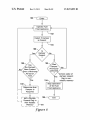
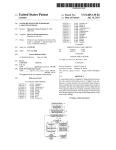
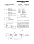
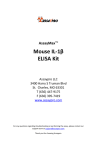
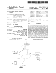
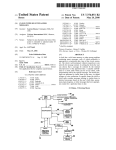
US008074892B2
(12) United States Patent
(10) Patent N0.:
(45) Date of Patent:
Bracken et al.
(54)
(56)
APPLIANCE CONTROL WITH AUTOMATIC
DAMPER DETECTION
References Cited
3,849,350
4,204,833
4,256,257
4,267,965
4,299,554
4,324,944
RE30,936
4,333,002
4,460,329
4,508,261
Brent Chian, Plymouth, MN (US);
Timothy J. Nordberg, Plymouth, MN
(US); Henry E. Troost, River Falls, WI
(Us)
(73) Assignee: Honeywell International Inc.,
Morristown, NJ (US)
Filed:
(Continued)
U.S. Appl. No. 10/911,151, ?led Aug. 3, 2004.
(Continued)
Primary Examiner * Marc Norman
(74) Attorney, Agent, or Firm * Seager, Tufte & Wickhem
LLC
Jul. 8, 2010
(57)
Related U.S. Application Data
ABSTRACT
Methods and systems for operating a fuel ?red appliance that
Continuation of application No. 11/276,121, ?led on
Feb. 15, 2006, now Pat. No. 7,721,972, which is a
may include an optional hardware component such as a
damper are disclosed. In some cases, the presence of the
continuation-in-part of application No. 11/306,875,
optional hardware component is detected, and it is deter
mined whether the optional hardware component is required
for future operation of the fuel ?red appliance. The fuel ?red
appliance may be operated normally if the optional hardware
?led on Jan. 13, 2006, now Pat. No. 7,747,358.
Int. Cl.
F23N 5/00
component is present and required, or, in some cases, if the
optional hardware component is determined to be not
(2006.01)
U.S. Cl. ..... .. 236/1 H; 236/11; 236/15 R; 236/21 R;
required. If the optional hardware component is absent but
required, normal operation of the fuel ?red appliance may be
236/46 E
(58)
3/1990
OTHER PUBLICATIONS
Prior Publication Data
US 2010/0173252 A1
(52)
0356609
Mar. 23, 2010
(65)
Matsko
KmetZ etal.
Pinkerton
Everett
Williams
Wiehrich et a1.
KmetZ et :11.
Kozak
Trent
Blank
FOREIGN PATENT DOCUMENTS
EP
(21) Appl. N0.: 12/729,778
(51)
ll/l974
5/1980
3/1981
5/1981
ll/l98l
4/1982
5/1982
6/1982
7/1984
4/1985
(Continued)
This patent is subject to a terminal dis
claimer.
(63)
A
A
A
A
A
A
E
A
A
A
Subject to any disclaimer, the term of this
patent is extended or adjusted under 35
U.S.C. 154(b) by 0 days.
(22)
*Dec. 13, 2011
U.S. PATENT DOCUMENTS
3,847,350 A
ll/l974 Thompson
(75) Inventors: Scott J. Bracken, Long Lake, MN (US);
Notice:
US 8,074,892 B2
Field of Classi?cation Search ................ .. 236/1 H,
stopped.
236/10,11,15 R, 20 R, 21 R, 46 E
See application ?le for complete search history.
20 Claims, 8 Drawing Sheets
140
Detect if Damper
is Present
Damper
Present
was
Darn per
Previously
Detected
?
Stop Operation
of the Fuel
[150
Fired Appliance
Controlling the Fuel
Fired Appliance in
Controlling the Fuel
Fired Appliance in
Accordance with a
First Control
Accordance with a
Second Control
Algorithm
Algorithm
US 8,074,892 B2
Page 2
US. PATENT DOCUMENTS
4,511,790
4,538,980
4,588,875
4,692,598
4,696,639
4,734,658
4,742,210
4,752,210
4,770,629
4,834,284
4,835,670
4,880,376
4,984,981
4,986,468
5,007,156
5,039,006
5,276,630
5,442,157
5,622,200
5,660,328
5,797,358
5,896,089
5,968,393
5,975,884
6,048,193
6,053,130
6,059,195
6,208,806
6,261,087
6,271,505
6,293,471
6,350,967
RE37,745
D>
B1
B1
B1
B1
B1
E
4/1985
9/1985
5/1986
9/1987
9/1987
3/1988
5/1988
6/1988
9/1988
5/1989
5/1989
11/1989
1/1991
1/1991
4/1991
8/1991
1/1994
8/1995
4/1997
8/1997
8/1998
4/1999
10/1999
11/1999
4/2000
4/2000
5/2000
3/2001
7/2001
8/2001
9/2001
2/2002
6/2002
KoZak
Hoyme
KoZak et al.
Yoshida et al.
Bohan, Jr.
Bohan, Jr.
Tsuchiyama et al.
Trent
Bohan, Jr.
Vandermeyden
Adams et al.
Bartels et al.
Pottebaum
Deisinger
Hurtgen
Habegger
Baldwin et al.
Jackson
SchulZe
Momber
Brandt et al.
Bowles
Demaline
Dugger
Juntunen et al.
Shellenberger
6,560,409 B2
B1
B2
B2
B2
B1
6,701,874
6,955,301
6,959,876
7,205,892
7,221,862
2001/0025349
2001/0031138
2002/0132202
2004/0176859
2004/0185770
2005/0077368
2005/0161516
2006/0214015
2007/0023333
A1
A1
A1
A1
A1
A1
A1
A1
A1
5/2003 Troost, IV
Schultz et al.
Munsterhuis et al.
Chian et al.
Luebke et al.
Miller et al.
3/2004
10/2005
11/2005
4/2007
5/2007
9/2001
10/2001
9/2002
9/2004
9/2004
4/2005
7/2005
9/2006
2/2007
Sharood et al.
Troost, IV
Clifford
Chian et al.
Soeholm et al.
Zak et al.
Munsterhuis
Furukawa et al.
Mouhebaty et al.
FOREIGN PATENT DOCUMENTS
EP
GB
0356609
2211331
3/2006
6/1989
OTHER PUBLICATIONS
Honeywell D896 Automatic Vent Damper, Product Data, 12 pages,
1997.
Honeywell S8610U Universal Intermittent Pilot Module, Installation
Instructions, 20 pages, Aug. 1996.
Johnson Controls Q135 Automatic Flue Damper System, 8 pages,
Adams et al.
1998.
Langford
LennoX, “Network Control Panel (NCP), User’s Manual,” 18 pages,
Bird et al.
Henderson
Stettin et a1.
Scott
Brandt et al.
Nov. 1999.
US . Appl. No. 10/911,151, entitled “Water Heater and Control,” ?led
Aug. 3, 2004.
Weil-McLain, Technical Services Bulletin No. SB201, 2 pages, Nov.
20, 2002.
US. Patent
Dec. 13, 2011
Sheet 1 of8
US 8,074,892 B2
40—~
?\
I ___'_
24
_
____
[34 1/26
_'_'__J___
____
14"
42
v53
figure 1
US. Patent
Dec. 13, 2011
Sheet 2 of8
US 8,074,892 B2
Damper Control
Signa|(s)
53*
Water Heater
59-—~
Input Slgnals
l
50
65w
/
I’ l _ _ ‘l
M_en_'1o_ryJ Processor
[54
[56
Damper
Function
Detector
Control
63
l
Water Heater
Control Signals
figure 2
US. Patent
Dec. 13, 2011
Sheet 3 of8
US 8,074,892 B2
@m385
US. Patent
Dec. 13, 2011
Sheet 4 of8
_
mEHmwnEoN¢
mEHwmanEoNv
US 8,074,892 B2
mwEHmonENw
US. Patent
Dec. 13, 2011
120‘
Sheet 5 of8
l
Enter
US 8,074,892 B2
l
l
ll
Detect if Damper :
is Present
\122
124
Is
Damper
Present
'2
\
ll
ll
Controlling the Fuel
Fired Appliance in
Controlling the Fuel
Fired Appliance in
Accordance with a
Accordance with a
First Control
Second Control
Algorithm
Algorithm
figure 5
US. Patent
Dec. 13, 2011
Sheet 6 of8
US 8,074,892 B2
140
Detect if Damper
is Present
k142
144
Is
Damper
Present
?
148
Was
Damper
Yes
Previously
Detected
152\
Stop Operation
146
\
of the Fuel
v
150
Fired Appliance
f
Controlling the Fuel
Fired Appliance in
Controlling the Fuel
Fired Appliance in
Accordance with a
Accordance with a
First Control
Second Control
Algorithm
Algorithm
figure 6
US. Patent
Dec. 13, 2011
Sheet 7 of8
160
Detect if Damper
is Present
166
Was
Damper
Previously
Detected
Stop Operation
of the Fuel
Fired Appliance
170
figure 7
US 8,074,892 B2
US. Patent
Dec. 13, 2011
180‘1
Sheet 8 of8
Enter
US 8,074,892 B2
)
ll
Operate Fuel
Fired Appliance
‘'
\182
Detect if Damper
is Present
\184
186
Is
Damper
Present
Damper
Previously
Been Present
Period of
Check state of
damper present
flag in non
volatile memory
190\
Stop Operation
_
of the Fuel
Determ'ne Phat
Fired Appliance
Damper IS
Required
|—Set a Damper—|
|_ _| Present Flag in
196
Non-Volatile
|_ _Me?’ry_ JLigi
figure 8
US 8,074,892 B2
1
2
APPLIANCE CONTROL WITH AUTOMATIC
DAMPER DETECTION
times for a minimum period of time), determining that the
This application is a continuation of Us. patent applica
tion Ser. No. 11/276,121, entitled “Applicant Control With
Automatic Damper Detection”, ?led Feb. 15, 2006, Which is
a continuation-in-part of Us. patent application Ser. No.
damper if a damper Was previously installed. As such, the
method may further include the steps of: operating the fuel
damper is noW required. In some cases, it may not be desir
able to alloW the fuel ?red appliance to operate Without a
?red appliance if the damper is present and required; operat
ing the fuel ?red appliance if the damper is not present and not
required; and ceasing to operate the fuel ?red appliance nor
mally if the damper is not present but required. The ceasing to
11/306,875, entitled “Building Equipment Component Con
trol With Automatic Feature Detection”, ?led Jan. 13, 2006,
both of Which are incorporated herein by reference.
operate step may include, for example, preventing or stopping
the fuel ?red appliance from combusting fuel in the combus
tion chamber. This may be accomplished by, for example,
FIELD
inhibiting an igniter (if present) from igniting the fuel, pre
venting a fuel valve that supplies fuel to the combustion
The present invention relates generally to fuel ?red appli
ances such as Water heaters, furnaces and boilers, and more
chamber from opening, turning off a pilot ?ame (if present),
particularly, to control systems and methods for controlling
such fuel ?red appliances.
terminating all poWer to the fuel ?red appliance, and/or any
other suitable method of ceasing to operate the fuel ?red
BACKGROUND
appliance in a normal manner, as desired.
In some cases, once a damper is detected for at least the
20
(e. g. atmosphere) via a vent pipe or the like. During off-cycle
periods, the fuel ?red appliances can lose signi?cant heat
through the vent pipe or chimney by natural convection and/
or conduction. To help reduce these losses, a damper can be
installed either at the ?ue exit or in the vent pipe. Alterna
tively, tWo or more dampers may be used, such as a ?ue
damper installed upstream of a draft diverter of the fuel ?red
appliance, and a vent damper installed doWnstream of the
draft diverter.
In some cases, electric motor controlled ?ue dampers may
be used and controlled by a damper controller or the like. In
some cases, the damper(s) may be controlled to open When
combustion starts, and close immediately or sometime after
25
state of the damper present ?ag may be saved, even in the
event of a poWer failure. As noted above, the damper present
?ag, When set, may indicate that a damper is noW required in
order to operate the fuel ?red appliance. The damper present
?ag may be active loW or high, as desired.
During subsequent operation of the fuel ?red appliance, the
30
status of the damper present ?ag may be checked to see if a
damper Was previously detected and noW deemed to be
required. If a damper is deemed to be required, the fuel ?red
appliance may be operated normally if the damper is present,
35
but stopped or otherWise not operated normally if a damper is
not currently present. If the status of the damper present ?ag
does not indicate a damper Was previously present, and thus
the presence of the damper is not required, the fuel ?red
appliance may be operated normally Without a damper
present.
combustion stops. This may help minimiZe the off-cycle heat
losses that may occur through the vent pipe or chimney of
many fuel ?red appliances.
minimum period of time, a damper present ?ag is set in a
memory, such as a non-volatile memory. The damper present
?ag may include a single bit in the memory, or a collection of
bits, as desired. When provided in a non-volatile memory, the
Commercial and residential buildings often use fuel ?red
appliances such as Water heaters, furnaces and boilers. In
many cases, the fuel ?red appliances include a combustion
chamber With a ?ue that is vented to outside of the building
40
In some cases, the damper may be a motoriZed damper that
has one or more conductors ?tted to a ?rst connector. The one
SUMMARY
or more conductors may provide poWer and/ or control signals
to the motoriZed damper. A damper detector may be coupled
The folloWing summary of the invention is provided to
facilitate an understanding of some of the innovative features
unique to the present invention and is not intended to be a full
45
to a second connector that is adapted to be selectively con
nected to the ?rst connector of the motoriZed damper. A
controller for the fuel ?red appliance may include, or be
description. A full appreciation of the invention can be gained
coupled to, the damper detector. When the damper detector
by taking the entire speci?cation, claims, draWings, and
detects that the ?rst connector is connected to the second
connector, a damper present ?ag may be set in a memory,
recording that a damper has been detected. In some cases, the
abstract as a Whole.
The present invention relates generally to fuel ?red appli
50
ances, and more particularly, to control systems and methods
damper present ?ag is not set until the damper detector detects
for operating such fuel ?red appliances. The fuel ?red appli
that the ?rst connector is connected to the second connector
for a minimum period of time.
ance may be, for example, a Water heater, a furnace, a boiler,
or any other fuel ?red appliance as desired. The fuel ?red
appliance may have a combustion chamber With a ?ue exit
The controller may include, or may be coupled to, the
55
damper detector and may be adapted to read the damper
present ?ag from memory. The controller may stop normal
operation of the fuel ?red appliance if the state of the damper
present ?ag is set and the damper detector detects that the ?rst
60
The controller may alloW normal operation of the fuel ?red
appliance if the state of the damper present ?ag is not set and
the damper detector detects that the ?rst connector is not
that is vented to atmosphere (e.g. outside the building) via a
vent pipe or the like.
In some embodiments, a controller is provided that con
trols the fuel ?red appliance, and in some cases, an optional
damper. The optional damper may, for example, be a vent or
connector is no longer connected to the second connector.
?ue damper that, When installed, selectively opens and closes
the exhaust path to atmosphere in the vent and/or ?ue. In some
cases, the damper may be installed in, for example, the ?ue
exit of the fuel ?red appliance, and/ or in the vent pipe, to help
minimize the off-cycle heat losses of the fuel ?red appliance.
One illustrative method includes the step of detecting if an
optional damper is present, and if a damper is present (some
connected to the second connector or, in some cases, has not
been connected to the second connector for at least a mini
65
mum period of time.
In another illustrative embodiment, the presence of a
damper may be detected. If a damper is detected, the fuel ?red
US 8,074,892 B2
3
4
appliance may be controlled in accordance With a ?rst control
Insulating layer 14 may be located betWeen outer surface
32 of tank 12 and external shell 16. Insulating layer 14 limits
algorithm. If a damper is not detected, the fuel ?red appliance
or otherWise minimiZes the heat loss of the heated Water from
passing from tank 12 to the outside World. Bonded to the
inside of inner surface 22 is rust inhibiting liner 30. In addi
tion, tank 12 may have a sacri?cial anode rod (not illustrated)
may be controlled in accordance With a second control algo
rithm. In some cases, normal operation of the fuel ?red appli
ance may be stopped if a damper is detected as present over a
minimum period of time, and then subsequently not detected.
to keep tank 12 from corroding.
Tank 12 also has a top surface 34 and a bottom surface 36.
BRIEF DESCRIPTION
Dip tube 24 and output pipe 26 pass through top surface 34.
Output pipe 26 extends through top surface 34 to a second
The invention may be more completely understood in con
predetermined distance from bottom surface 36. This second
predetermined distance may be fairly close to top surface 34.
Positioning output pipe 26 close to top surface 34 alloWs the
sideration of the following detailed description of various
embodiments of the invention in connection With the accom
panying drawings, in Which:
hotter Water, Which may be the hottest Water in tank 12, to exit
upon demand. In operation, When the hot Water is demanded,
fresh Water ?oWs into dip tube 24 to the bottom of tank 12 and
FIG. 1 is cutaWay side vieW of an illustrative fuel ?red
appliance;
FIG. 2 is a block diagram of an illustrative controller for
pushes or otherWise causes the hotter Water at the top of tank
operating and/ or controlling the fuel ?red appliance of FIG. 1;
FIG. 3 is a schematic diagram of an illustrative damper
detector;
20
12 to exit through output pipe 26.
Dip tube 24 extends through top surface 34 to a predeter
mined distance from bottom surface 36. This predetermined
distance may be fairly close to bottom surface 36. Positioning
FIGS. 4A-4C shoW graphs of illustrative feedback signals
for the damper detector of FIG. 3 under various operating
the exit of dip tube 24 close to bottom surface 36 alloWs the
conditions;
fresh, cold or ambient Water to enter tank 12 near bottom
FIG. 5 is a ?oW diagram of an illustrative method for
controlling a fuel ?red appliance;
25
FIG. 6 is a ?oW diagram of another illustrative method for
controlling a fuel ?red appliance;
FIG. 7 is a ?oW diagram of another illustrative method for
controlling a fuel ?red appliance; and
FIG. 8 is a ?oW diagram of another illustrative method for
controlling a fuel ?red appliance.
While the invention is amenable to various modi?cations
and alternative forms, speci?cs thereof have been shoWn by
Way of example in the draWings and Will be described in
detail. It should be understood, hoWever, that the intention is
30
surface 36. This helps prevent the cold or ambient Water from
mixing and cooling the hotter Water near top surface 34. In
practice, dip tube 24 may be located about three quarters of
the distance from top surface 34 to bottom surface 36.
Because the cooler Water entering tank 12 is denser than
heated Water, the cooler Water tends to sink to the bottom of
tank 12, Where it may be heated.
Heater 18 heats tank 12, Which in turn heats any Water
inside tank 12. In the illustrative embodiment, heater 18 may
be one or more gas-?red burners located in a combustion
35
chamber 43. In the exemplary gas-?red Water heater 10
shoWn in FIG. 1, heater 18 may have a gas-?oW valve (not
shoWn), a burner 38 and an ignition source 40. The gas-?oW
valve may be a solenoid-controlled valve, a linear actuated
valve, a motor actuated valve, or any other valve capable of
not to limit the invention to the particular embodiments
described. On the contrary, the intention is to cover all modi
?cations, equivalents, and alternatives falling Within the spirit
and scope of the invention.
40
supplying gas to burner 38. Ignition source 40 may be a pilot
light, a solid-state igniter, an electric heat element, or any
other ignition source capable of igniting gas.
The heat output of heater 18 may be controlled by burner
ori?ce siZe, gas pressure, and/or time. To produce heat in the
DESCRIPTION
The folloWing description should be read With reference to
the draWings Wherein like reference numerals indicate like
elements throughout the several vieWs. The draWings, Which
are not necessarily to scale, depict selected embodiments and
tion source 40 ignites the gas. The gas Will continue to burn
are not intended to limit the scope of the invention. Although
until the supply of gas is terminated. The burner 38, Which is
gas-?red Water heater, gas ?oWs into burner 38 in the com
bustion chamber 43 through the gas-?oW valve, Where igni
examples of construction, dimensions, and materials are
situated in combustion chamber 43, may be in ?uid commu
illustrated for the various elements, those skilled in the art Will
nication With an exhaust outlet, such as a ?ue 40. The ?ue 40
may be coupled to a vent pipe 45 that vents combustion gases
recogniZe that many of the examples provided have suitable
50
exiting from the combustion chamber 43 to atmosphere (e.g.
outside of the building).
alternatives that may be utiliZed.
The present invention relates generally to fuel ?red appli
ances such as Water heaters, furnaces and boilers, and more
In some cases, the combustion gases may be vented
particularly, to control systems and methods for such fuel
?red appliances. Merely for illustrative purposes, and not to
be intended as limiting in any manner, the present invention
through the ?ue 40 and vent pipe 45 through natural convec
tion. Alternatively, a fan or like (not shoWn) may be provided
to help force the combustion gases through the ?ue 40 and
vent pipe 45 to atmosphere. In either case, during off-cycle
periods, the Water heater 10 can lose heat through the ?ue 40
and vent pipe 45 to atmosphere by natural convection and
conduction. To help reduce these losses, a damper 49 may be
55
Will be discussed With respect to a gas ?red Water heater,
although as indicated above, any suitable gas ?red appliance
may be used, as desired.
FIG. 1 is cutaWay vieW of an illustrative Water heater 10.
The illustrative Water heater 10 includes a tank 12, an insu
lating layer 14, an external shell 16, a heater 18, and a con
troller 50. Tank 12 holds Water that is to be heated and may be
constructed of steel or other heat conducting material. Illus
trative tank 12 has an inner surface 22, an input supply tube or
dip tube 24, an output conduit or pipe 26, a drainage valve 28,
a rust inhibiting liner 30, and an outer surface 32.
60
installed either at the ?ue 40 exit or in the vent pipe 45.
Alternatively, tWo or more dampers may be used, such as a
?ue damper (not shoWn) installed up stream of a draft diverter
(if present) of the Water heater, and a vent damper 49 installed
65
doWnstream of the draft diverter (if present).
In some cases, one or more electric motor controlled damp
ers may be used. The damper 49 shoWn in FIG. 1 may be one
US 8,074,892 B2
5
6
such electric motor controlled damper. The damper 49 may be
tive, and it is contemplated that any suitable detection method
or signal may be provided by the damper detector block 54, as
desired.
One illustrative method of the present invention includes
controlled by a controller 50 or the like via Wiring 53. In some
cases, the damper(s) 49 may be controlled to open When
combustion in the combustion chamber 43 starts, and close
immediately or sometime after combustion stops. This may
help minimize the off-cycle heat losses that may occur
the step of detecting if damper 49 is present using damper
detector block 54, and if the damper 49 is present, sometimes
through natural convection through the vent pipe 45 to atmo
for at least a minimum period of time. In some embodiments,
sphere.
the minimum period of time may represent, for example, a
FIG. 2 is a block diagram of an illustrative controller 50 for
operating and/or controlling the Water heater 10. The illustra
tive controller 50 includes a damper detector block 54, a
function control block 56, a processing block 52, and a
memory block 58. The functions of the illustrative controller
50 may be implemented in hardWare, softWare or a combina
tion thereof Under some circumstances, the damper detector
predetermined minimum elapse time period, a predetermined
minimum number of heating cycles of the Water heater 10
(eg one, tWo, three or greater), or any other minimum time
period as desired, Whether predetermined or not. If the
damper detector block 54 detects the presence of the damper
49, sometimes for at least the minimum period of time, the
processing block 52 may determine that the damper 49 is
required during sub sequent operation of the Water heater 10.
block 54, the function control block 56, the processing block
52, and/ or the memory block 58 may be integrated on a single
In some cases, it may not be desirable to alloW the Water
device platform, but this is not required.
In the illustrative embodiment, the controller 50 may con
trol the operation of the Water heater 10. For example, the
controller 50 may control the ignition source or pilot of the
Water heater, control the opening and closing of a gas valve,
20
control the opening and closing of the optional damper 49, as
Well as control the operation of other components, depending
on the application. The controller 50 may provide one or more
25
The ceasing to operate step may include, for example,
Water heater control signal signals, as shoWn at 63, to various
components of the Water heater 10, and may receive one or
more Water heater input signals 65 from Water heater 10, such
as one or more sensor (e.g. temperature sensor) input signals,
one or more user interface input signals, etc.
30
The processing block 52 of the controller 50 may, in some
cases, process one or more of the input signals 65, and in
response, provide appropriate control signals 63 to the vari
ous Water heater 10 components, sometimes through the
function control block 56. For example, and in some cases,
the function control block 56 may be adapted to control the
35
40
The memory block 58 may be included internally to the
processing block 52, and/or may be separately provided, as
desired. The memory block 58 may store programming,
45
damper present ?ag and/or the like. The memory block 58
interrupted or turned off. The memory block 58 may include,
50
memory, RAM memory, registers, and/ or any other type of
memory as desired.
55
damper Was previously detected and noW deemed to be
required for future operation of the Water heater 10. If a
damper 49 is deemed to be required, the Water heater 10 may
does not indicate a damper 49 Was previously present and is
therefore not noW required, the Water heater 10 may be oper
ated normally Without a damper 49 present.
coupled to, the processing block 52 of the controller 50, if
desired. Under some circumstances, the damper detector
In some cases, the damper 49 may be a motoriZed damper
that has one or more conductors 53 ?tted to a ?rst connector
59. The one or more conductors 53 may convey poWer and/ or
block 54 may be a detection circuit, Which may provide an
electrical signal to the processing block 52 that indicates
Whether a damper 49 is present and connected.
For example, and as Will be discussed in further detail
beloW, the damper detector block 54 may provide a ?rst
electrical signal to the processing block 52 When a damper 49
is present and connected to the controller 50, and no signal or
a second signal When the damper 49 is not present or not
connected to the controller 50. HoWever, this is only illustra
During subsequent operation of the Water heater 10, the
be operated normally if the damper 49 is still present, but
stopped or otherWise not operated normally if the damper 49
is not currently present. If the status of the damper present ?ag
able programmable read-only memory (EEPROM), ?ash
The damper detector block 54 may be used to detect When
a damper (such as damper 49 of FIG. 1) is present and con
nected. The damper detector block 54 may be internal, or
the damper present ?ag may be maintained, even in the event
of a poWer failure. As noted above, the damper present ?ag,
When set, may indicate that a damper 49 is noW required in
order to operate the Water heater 10 normally. The damper
present ?ag may be active loW or high, as desired.
processing block 52 may read up the status of the damper
present ?ag from the memory block 58, and check to see if a
may, in some cases, include a non-volatile memory that
retains its contents even after poWer to the memory 58 is
for example, a read-only memory (ROM), electrically eras
to operate the Water heater 10 in a normal manner, as desired.
In some cases, once a damper 49 is detected, sometimes for
single bit in the memory block 58, or a collection of bits, as
desired. When provided in a non-volatile memory, the state of
required.
parameter values, historical data, one or more ?ags such as a
preventing or stopping the Water heater 10 from combusting
fuel in the combustion chamber 43. This may include manipu
lating the control signals 63 to, for example, inhibit an igniter
(if present) from igniting the fuel, prevent a fuel valve that
supplies fuel to the combustion chamber 43 from opening,
turn off a pilot ?ame (if present), terminate all poWer to the
Water heater 10, and/ or any other suitable method of ceasing
at least a minimum period of time, a damper present ?ag is set
in memory block 58. The damper present ?ag may include a
ignition of the burner and/or the ignition source by either
alloWing ignition of the Water heater 10 or not alloWing igni
tion of the Water heater 10. It is contemplated that the pro
cessing block 52 may include a microprocessor, but this is not
heater 10 to continue to operate Without the damper 49 if the
damper 49 Was previously installed and detected. As such, the
method may further include the steps of: operating the Water
heater 10 if the damper 49 is present and determined to be
required; operating the Water heater 10 if the damper 49 is not
present and not determined to be required; and ceasing to
operate the Water heater 1 0 if the damper 49 is not present and
determined to be required.
60
control signals to the damper 49. The damper detector block
54 may be coupled to a second connector 61, Which is adapted
to be selectively connected to the ?rst connector 59 of the
damper 49. The processing block 52 may include, or be
coupled to, the damper detector block 54. When the damper
65
detector block 54 detects that the ?rst connector 59 is con
nected to the second connector 61 (sometimes for a minimum
period of time, minimum number of heating cycles, etc.), a
US 8,074,892 B2
8
7
damper present ?ag may be set in the memory block 58,
recording that the damper 49 has been detected.
The processing block 52 may be adapted to read the
damper present ?ag from memory block 58. This may occur
in real time, periodically, at the beginning or end of a heating
cycle, and/or at any other time, as desired. The processing
block 52 may stop normal operation of the Water heater 10 if
the state of the damper present ?ag is set and the damper
To detect Whether a damper is present and connected, the
?rst connector 76 may have a line 80 that is connected to a ?rst
voltage divider 82. The ?rst voltage divider 82 may include a
?rst resistor 84 and a second resistor 86 connected in series.A
damper present feedback signal 88 may be taken from the ?rst
voltage divider 82 and provided to the micro-controller 62, as
shoWn. When a damper 64 is provided, line 80 of the ?rst
connector 76 is connected to the second connector 74. Inside
detector block 54 detects that the ?rst connector 59 is no
of the second connector 74, or inside the damper 64 assembly
longer connected to the second connector 61. The processing
block 52 may alloW normal operation of the Water heater 10 if
the state of the damper present ?ag is not set and the damper
minal of the motor 72. Thus, if the ?rst connector 76 is
connected to the second connector 74 (eg the damper is
detector block 54 detects that the ?rst connector 59 is not
present), line 80 Will be coupled to the “C” signal 68. HoW
itself, line 80 may be connected to the common or “C” ter
ever, if the ?rst connector 76 is not connected to the second
connected to the second connector 61 or, in some cases, has
not been connected to the second connector 61 for at least a
minimum elapse period of time, a minimum number of heat
ing cycles, etc.
In some embodiments, if a damper 49 is detected by the
damper detector block 54, the controller 50 may control the
Water heater 10 in accordance With a ?rst control algorithm.
20
The ?rst control algorithm may, for example, be adapted to
control the Water heater 1 0 in conjunction With the damper 49.
If a damper 49 is not detected by the damper detector block
54, the controller 50 may control the Water heater 10 in
accordance With a second control algorithm. The second con
damper.
25
trol algorithm may, for example, be adapted to control the
Water heater 10 Without the damper 49. In some cases, the
normal operation of the Water heater 10 may be stopped if a
damper 49 is detected by the damper detector block 54, some
times for a minimum period of time, and then subsequently
connector 74 (eg the damper is not present), line 80 Will be
pulled to ground via the ?rst voltage divider 82.
The illustrative damper detector 60 may also be con?gured
to detect When the damper 64 has reached an end position
(e.g. fully open position). The damper 64 may include an end
detect sWitch 89, Which in the illustrative embodiment, is
closed When the damper has reached an end position (eg a
fully open position) and the motor has ?nished moving the
30
In the illustrative embodiment, the ?rst connector 76 may
have a line 90 that is connected to a second voltage divider 92.
The second voltage divider 92 may include a ?rst resistor 94
and a second resistor 96 connected in series. A damper end
detect feedback signal 98 may be taken from the second
voltage divider 92 and provided to the micro-controller 62, as
shoWn. When a damper 64 is provided, line 90 of the ?rst
not detected.
connector 76 is connected to the second connector 74. Inside
FIG. 3 is a schematic diagram of an illustrative damper
detector 60. The illustrative damper detector 60 includes a
of the second connector 74, or inside the damper 64 assembly
micro-controller 62, an optional damper 64, a damper relay
70, an end detect sWitch 89, and tWo voltage dividers 84 and
35
itself, line 90 may be connected to one terminal of the end
detect sWitch 89 as shoWn. The other terminal of the end
detect sWitch may be connected to the “R” terminal of the
motor 72. Thus, When a damper 64 is provided, and the ?rst
92.
In the illustrative embodiment, poWer is supplied by a 24V
connector 76 is connected to the second connector 74, line 90
AC poWer signal including an “R” signal 66 and a common
“C” signal 68. PoWer signals R 66 and C 68 may be a 24-volt
Will be coupled to the “R” signal 66 When the end detect
sWitch 89 is closed (eg the damper has reached a fully open
AC poWer signal, typically provided by a step doWn trans
former, With the R and C signals 180 degrees out of phase
40
In this con?guration, the damper end detect feedback sig
nal 98 Will generally folloW the damper activation signal 78,
relative to one another. In the illustrative embodiment, the C
signal 68 is coupled to a C terminal of a ?rst connector 76, and
the R signal 66 is coupled to an R terminal of the ?rst con
nector 76.
The illustrative damper 64 includes a motor 72 for moving
the damper betWeen an open position and a closed position.
The motor 72 includes poWer inputs R and C. In the illustra
tive embodiment, the R input of the motor 72 is coupled to an
R terminal of a second connector 74, through relay 70. The C
input of the motor 72 is coupled to a C terminal of a second
connector 74. When the damper is provided, the second con
nector 74 is coupled to the ?rst connector 76, Which electri
cally connects the R and C terminals of the ?rst connector 76
to the R and C terminals of the second connector 74.
but it does not have to if the damper motor 72 is broken. The
damper end detect feedback signal 98 Will also be delayed
45
air How) the end detect sWitch 89 is closed providing “R” to
the voltage divider 92. If a damper 64 is not provided, the ?rst
50
55
the C signal 68, the damper present feedback signal 88, and
the damper actuation feedback signal 98, When there is no
damper 64 present and the damper actuation relay 70 is open.
Referenced from the ?oating controller ground, the R signal
60
damper activation signal 78, Which selectively closes the
position of the damper 64.
connector 76 is not connected to the second connector 74, and
line 90 Will be pulled to ground via the second voltage divider.
FIG. 4A-4C are graphs shoWing illustrative feedback sig
nals for the damper detector 60 of FIG. 3 under various
conditions. FIG. 4A is an illustrative graph of the R signal 66,
terminal, Which in the illustrative embodiment, is coupled to
the control input of relay 70. Thus, When a damper 64 is
provided, the micro-controller 62 selectively activates the
relay 70 and supplies the R signal 66 to the R terminal of the
motor 72, thereby activating the motor 72 and moving the
relative to the damper activation signal 78 due to the time it
takes for the motor 72 to turn the damper to the fully open
position. Generally When the damper is fully open (alloWing
During operation, and in the illustrative embodiment, the
micro-controller 62 selectively supplies a damper activation
signal 78. The damper activation signal 78 is coupled to a
damper activation terminal of the ?rst connector 76. The
second connector 74 has a corresponding damper activation
position).
65
66 and the C signal 68 appear like half Wave recti?ed 24-volt
AC poWer signal 180 degrees out of phase relative to one
another. Because the damper is not present in FIG. 4A, and
referring back to FIG. 3, the ?rst connector 76 is not con
nected to the second connector 74, and thus line 80 is pulled
to ground via the ?rst voltage divider 82. Thus, the damper
present feedback signal 88 Will also be pulled to ground, as
shoWn in FIG. 4A. LikeWise, because the ?rst connector 76 is
not connected to the second connector 74, line 90 is pulled to
US 8,074,892 B2
10
ground via the second voltage divider, and the damper actua
dance With a ?rst control algorithm, and passes control back
tion feedback signal 98 Will also be pulled to ground, as
shown.
FIG. 4B is an illustrative graph of the R signal 66, the C
to step 122. Step 128 controls the fuel ?red appliance in
signal 68, the damper present feedback signal 88, and the
example, be adapted to control the fuel ?red appliance in
conjunction With a damper, and the second control algorithm
accordance With a second control algorithm, and passes con
trol back to step 122. The ?rst control algorithm may, for
damper actuation feedback signal 98, When a damper 64 is
present and connected, and the damper actuation relay 70 is
open. Referenced from the ?oating controller ground, the R
may be adapted to control the fuel ?red appliance Without a
damper.
signal 66 and the C signal 68 appear like half Wave recti?ed
24-volt AC poWer signal 180 degrees out of phase relative to
one another. Because the damper is present and connected,
the ?rst connector 76 is connected to the second connector 74,
and line 80 is coupled to the “C” signal 68.As can be seen, the
FIG. 6 is a How diagram of another illustrative method for
controlling a fuel ?red appliance. The How diagram is entered
at step 140. Step 140 may be entered continuously, periodi
damper present feedback signal 88 folloWs the “C” signal 68,
but at a reduced amplitude that is dictated by the relative
values of the ?rst resistor 84 and the second resistor 86 of the
?rst voltage divider 82. LikeWise, because the ?rst connector
76 is connected to the second connector 74, line 90 Will folloW
the “R” signal of the motor 72. HoWever, because the damper
actuation relay 70 is open in FIG. 4B, the “R” signal 66 is not
connected to the “R” signal of the motor 72. Thus, the damper
20
detected. If a damper Was not previously detected (in some
actuation feedback signal 98 Will also be pulled to ground
through the second voltage divider 92, as shoWn.
FIG. 4C is an illustrative graph of the R signal 66, the C
signal 68, the damper present feedback signal 88, and the
25
damper actuation feedback signal 98, When a damper 64 is
present and connected, and the damper actuation relay 70 is
closed. Referenced from the ?oating controller ground, the R
signal 66 and the C signal 68 appear like half Wave recti?ed
24-volt AC poWer signal 180 degrees out of phase relative to
one another. Because the damper is present and connected,
the ?rst connector 76 is connected to the second connector 74,
and line 80 is coupled to the “C” signal 68. Thus, the damper
present feedback signal 88 folloWs the “C” signal 68, but at a
reduced amplitude that is dictated by the relative valves of the
?rst resistor 84 and the second resistor 86 of the ?rst voltage
30
35
driven. In some cases, the damper present feedback signal 88
and/ or the damper actuation feedback signal 98 may be pro
vided to an analog-to-digital (A/D) converter before being
40
FIG. 7 is a How diagram of another illustrative method for
controlling a fuel ?red appliance. The How diagram is entered
at step 160. Step 160 may be entered continuously, periodi
45
50
cally, at the beginning or end of a heating cycle, or at any other
time, as desired. Control is passed to step 162. Step 162
detects Whether a damper is present, and passed control to
step 164. If a damper is present, step 164 passes control back
to step 162, and if a damper is not present, passes control to
step 166.
Step 166 determines if a damper Was previously detected.
If a damper Was not previously detected (in some cases, not
detected for a suf?ciently long period of time), control is
passed back to step 162. If a damper Was previously detected
(in some cases, detected for a suf?ciently long period of
time), control is passed to step 168. Step 168 stops operation
55
of the fuel ?red appliance, and passes control to step 170,
Wherein the How diagram is exited.
FIG. 8 is a How diagram of another illustrative method for
required.
controlling a fuel ?red appliance. The How diagram is entered
at step 180. Step 180 may be entered continuously, periodi
FIG. 5 is a How diagram of an illustrative method for
cally, at the beginning or end of a heating cycle, or at any other
time, as desired. Control is passed to step 122. Step 122
detects Whether a damper is present, and passed control to
step 124. If a damper is present, step 124 passes control to step
126, and if a damper is not present, step 124 passes control to
step 128. Step 126 controls the fuel ?red appliance in accor
over a minimum period of time or number of heating cycles),
and then subsequently not detected. Speci?cally With respect
to the illustrative method of FIG. 6, if step 148 determines that
a damper Was previously detected (in some cases, detected for
a suf?ciently long period of time or number of heating
of the fuel ?red appliance, and passes control to step 154,
Wherein the How diagram is exited.
provided to the micro-controller 62. In some cases, the micro
controller 62 may itself have A/D converters, but this is not
controlling a fuel ?red appliance. The How diagram is entered
at step 120. Step 120 may be entered continuously, periodi
In some cases, normal operation of the fuel ?red appliance
cycles), control is passed to step 152. Step 152 stops operation
present for a minimum period of time, over a minimum num
ber of heating cycles, etc. LikeWise, micro-controller 62 may
receive the damper actuation feedback signal 98, and may be
programmed to determine if the damper 64 is currently being
cases, not previously detected for a suf?ciently long period of
time), control is passed to step 150. Step 150 controls the fuel
?red appliance in accordance With a second control algo
rithm, and passes control back to step 142. The ?rst control
algorithm may, for example, be adapted to control the fuel
?red appliance in conjunction With a damper, and the second
control algorithm may be adapted to control the fuel ?red
appliance Without a damper.
may be stopped if a damper is initially detected (sometimes
divider 82. LikeWise, because the ?rst connector 76 is con
nected to the second connector 74, line 90 Will folloW the “R”
signal of the motor 72. Because the damper actuation relay 70
is closed in FIG. 4C, the “R” signal 66 is connected to the “R”
signal of the motor 72. Thus, the damper actuation feedback
signal 98 folloWs the “R” signal 66, but at a reduced ampli
tude that is dictated by the relative valves of the ?rst resistor
94 and the second resistor 96 of the second voltage divider 92.
The micro-controller 62 may receive the damper present
feedback signal 88, and may be programmed to determine if
a damper 64 is present. Furthermore, the micro-controller 62
may be programmed to determine if the damper 64 has been
cally, at the beginning or end of a heating cycle, or at any other
time, as desired. Control is passed to step 142. Step 142
detects Whether a damper is present, and passed control to
step 144. If a damper is present, step 144 passes control to step
146, and if a damper is not present, step 144 passes control to
step 148.
Step 146 controls the fuel ?red appliance in accordance
With a ?rst control algorithm, and passes control back to step
142. Step 148 determines if a damper Was previously
60
65
cally, at the beginning or end of a heating cycle, or at any other
time, as desired. Control is passed to step 182. Step 182
operates the fuel ?red appliance. Control is then passed to
step 184.
Step 184 detects if a damper is present, and passed control
to step 186. If a damper is present, step 186 passes control
back to step 188. Step 188 determines if the damper has been
present over a minimum period of time. The minimum period
US 8,074,892 B2
11
12
of time may represent a predetermined minimum elapsed
time period, a predetermined minimum number of heating
cycles of the fuel ?red appliance (eg one, tWo, three or
greater), or any other minimum time period as desired,
Whether predetermined or not. If the damper has not been
present for a minimum period of time, control is passed back
to step 182, Wherein the fuel ?red appliance is operated. If,
hoWever, the damper has been present for a minimum period
of time, control is passed to step 190. Step 190 determines that
the damper is noW required for normal operation of the fuel
a controller for controlling at least part of the operation of
the gas ?red appliance, the controller setting a damper
present ?ag in the non-volatile memory if the damper
detector detects that the plug of the optional damper is
received by the connector; and
the controller further ceasing to operate the gas ?red appli
ance if: (1) the damper detector does not currently detect
that the plug of the optional damper is received by the
connector; and (2) the damper present ?ag has been set
in the non-volatile memory.
2. The gas ignition controller of claim 1, Wherein the con
?red appliance. In some cases, step 190 sets a Damper Present
Flag in a non-volatile memory to indicate that the damper is
troller implements at least part of the damper detector.
noW required for normal operation.
Referring back to step 186, if a damper is not present,
control is passed to step 192. Step 192 determines if the
3. The gas ignition controller of claim 1, Wherein the con
troller is implemented separate from the damper detector.
4. The gas ignition controller of claim 3, Wherein the con
presence of a damper is required. In some cases, step 192 may
troller includes a microcontroller.
check the status of the Damper Present Flag in non-volatile
5. The gas ignition controller of claim 4, Wherein the
memory to determine if a damper is noW required. If a damper
is not required for normal operation of the fuel ?red appli
ance, control is passed back to step 182, Wherein the fuel ?red
appliance is operated. HoWever, if step 192 determines that a
damper is required, control is passed to step 194. Step 194
stops normal operation of the fuel ?red appliance, and passes
control to step 196, Wherein the How diagram is exited.
In some cases, once normal operation of the fuel ?red
microcontroller includes the non-volatile memory.
20
a ?rst resistor having a ?rst end and a second end;
a second resistor having a ?rst end and a second end; and
25
appliance is stopped, a service technician may be required to
inspect the fuel ?red appliance, replace the controller, reset
the Damper Present Flag in non-volatile memory, and/or per
form some other action to re-enable the fuel ?red appliance.
While a damper has been used as an example optional
hardWare component of a fuel ?red appliance, it is contem
suitable hardWare components, depending on the application,
and control the fuel ?red appliance in accordance With the
methods and systems described herein.
Having thus described the preferred embodiments of the
present invention, those of skill in the art Will readily appre
ciate that yet other embodiments may be made and used
Within the scope of the claims hereto attached. Numerous
advantages of the invention covered by this document have
been set forth in the foregoing description. It Will be under
stood, hoWever, that this disclosure is, in many respect, only
illustrative. Changes may be made in details, particularly in
matters of shape, siZe, and arrangement of parts Without
Wherein the ?rst end of the ?rst resistor is electrically
connected to the second end of the second resistor, and
Wherein the second end of the ?rst resistor is electrically
connected to ground.
7. The gas ignition controller of claim 1, Wherein the
damper detector includes:
30
a ?rst resistor;
a second resistor electrically coupled to the ?rst resistor;
plated that the present invention may be used for detecting the
presence of other hardWare, and controlling the fuel ?red
appliance accordingly. For example, rather than detecting the
presence of a damper, or in addition to detecting the presence
of a damper, the present invention may detect the presence of
a sensor (e. g. temperature sensor, CO sensor, ?ame sensor, IR
sensor, or other sensor), an ignition source, and/or any other
6. The gas ignition controller of claim 1, Wherein the
damper detector includes:
Wherein one end of the second resistor is coupled to a pin of
the connector.
35
8. The gas ignition controller of claim 1, further including
a voltage divider coupled to a pin of the connector, Wherein an
output of the voltage divider provides a damper end sWitch
detect signal.
40
45
9. The gas ignition controller of claim 8, Wherein the
damper end sWitch detect signal is provided to the controller.
10. The gas ignition controller of claim 1, Wherein poWer is
provided from the gas ignition controller to the optional
damper via the connector When the plug of the optional
damper is received by the connector.
11. A gas ignition controller for controlling at least part of
the operation of a gas ?red appliance, the gas ?red appliance
having a combustion chamber that is vented to atmosphere
via a vent, the gas ignition controller comprising:
a non-volatile memory;
50
a connector for receiving a plug of an optional damper,
Wherein the optional damper, When installed, can selec
tively open and close the vent of the gas ?red appliance
to atmosphere;
exceeding the scope of the invention. The invention’s scope
is, of course, de?ned in the language in Which the appended
claims are expressed.
a microcontroller for controlling at least part of the opera
What is claimed is:
1. A gas ignition controller for controlling at least part of
the operation of a gas ?red appliance, the gas ?red appliance
having a combustion chamber that is vented to atmosphere
via a vent, the gas ignition controller comprising:
a non-volatile memory;
55
communication With the connector and con?gured to
60
a connector for receiving a plug of an optional damper,
Wherein the optional damper, When installed, can selec
tively open and close the vent of the gas ?red appliance
to atmosphere;
a damper detector in communication With the connector for
detecting if the plug of the optional damper is received
by the connector; and
tion of the gas ?red appliance;
a damper detect circuit for providing a damper detect signal
to the microcontroller, the damper detect circuit is in
activate the damper detect signal if the plug of the
optional damper is received by the connector, the
damper detect circuit including:
a ?rst resistor having a ?rst end and a second end,
Wherein the second end of the ?rst resistor is con
nected to ground;
65
a second resistor having a ?rst end and a second end;
Wherein the ?rst end of the ?rst resistor is coupled to the
second end of the second resistor at a node, Wherein
US 8,074,892 B2
14
13
the node includes a signal that indicates if the plug of
the optional damper is received by the connector or
not;
the microcontroller receiving the damper detect signal
from the damper detect circuit and setting a damper
present ?ag in the non-volatile memory if the damper
detect signal is activated; and
the microcontroller ceasing operation of the gas ?red appli
ance if: (1) the damper detect circuit is not currently
activating the damper detect signal; and (2) the damper
present ?ag has been set in the non-volatile memory.
12. The gas ignition controller of claim 11, further includ
ing a voltage divider in communication With the connector,
Wherein an output of the voltage divider provides a damper
end sWitch detect signal to the microcontroller.
13. The gas ignition controller of claim 11, Wherein the
microcontroller includes the non-volatile memory.
14. The gas ignition controller of claim 11, Wherein poWer
is provided from the gas ignition controller to the optional
damper via the connector When the plug of the optional
damper is received by the connector.
15. The gas ignition controller of claim 11, Wherein the
signal at the node is the same as the damper detect signal.
16. A method of operating a fuel ?red appliance, the fuel
?red appliance having a combustion chamber that is vented to
atmosphere via a vent, the fuel ?red appliance further having
a controller for controlling the fuel ?red appliance as Well as
an optional damper that, When installed, can selectively open
and close the vent to atmosphere, the method comprising:
10
detecting if a damper is present;
controlling the fuel ?red appliance in accordance With a
?rst control algorithm that includes controlling the
damper, if the detecting step detects that the damper is
present; and
controlling the fuel ?red appliance in accordance With a
second control algorithm that does not include control
ling the damper, if the detecting step detects that the
damper is not present.
17. The method of claim 16, further comprising not alloW
ing the fuel ?red appliance to operate Without a damper
present if a damper Was previously detected as present.
18. The method of claim 16 further comprising ceasing to
operate the fuel ?red appliance Without a damper present if a
damper Was previously detected as being present.
19. The method of claim 16 further comprising ceasing to
operate the fuel ?red appliance if the detecting step detected
that the damper Was previously present, and subsequently
detects that the damper is no longer present.
20
25
20. The method of claim 19 further comprising:
setting a damper present ?ag in a non-volatile memory if
the detecting step detects that the damper is present; and
if the detecting step detects that the damper is not present,
checking to see if the damper present ?ag has been
previously set, and if the damper present ?ag has been
previously set, ceasing to operate the fuel ?red appli
ance.