1
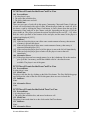
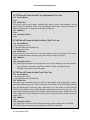
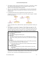
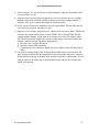
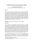
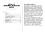
Use Case-based Requirements
This chapter gives an overall introduction to documenting requirements using use cases.
In this chapter, we will explain the following:
• the symbols found in a use case diagrams
• the relationships between the symbols in a use case diagram
• the textual description of a use case, the use case flow of events
It is quite likely that you have written code in an object-oriented language, such as Java
or C++. In these object-oriented languages, you have come to create your programs in
terms of classes where each class has its own data (via variables/attributes) and its own
behavior (via the class methods). In your programs, you create instances of these classes,
called objects. As your program runs, these objects interact with each other to implement
the system functionality.
In this chapter we will discuss a means of documenting your stakeholder functional
requirements in a way that will more easily lead you to discover what classes you will
need to implement. This approach is called the use cases approach (Jacobson,
Christerson et al., 1992). When you document your requirements using use cases, these
use cases are then valuable during the next steps in your project development – such as in
the design and testing activities. Also, it will be easier to write your user manual if you
have documented your requirements by means of use cases.
When we document requirements using use cases, we use textual description along with
use case diagrams. The use case diagram is a part of the Unified Modeling Language
(Rumbaugh, Jacobson et al., 1999), more commonly referred to as UML. In this chapter,
we will first introduce you to UML. Then, we will show you how to document your
requirements using use cases.
1
An Introduction to UML
UML is a modeling language or graphical/diagrammatic notation for object-oriented
programming – a way to express the “blueprints” of your system. Within UML, there are
several types of diagrams. Some of them are:
• Use case diagrams for requirements
• State diagrams for object-oriented analysis
• Class diagrams and sequence diagrams for object-oriented design
As a software engineer, you need to become well-versed in these UML diagrams. As you
head towards your professional life, your peers will simply assume that you know these
diagrams. When you brainstorm together, your co-workers will quickly draw one of
these diagrams on a whiteboard without explaining the symbols or notations, fully
expecting that you understand. Or, you might receive UML-based requirements, analysis,
or design documents that you will need to work with.
Use Case-based Requirements
Once you know UML, you can also communicate with your peers using the diagrams too.
You know the old adage, “A picture is worth a thousand words.” You can spend a few
moments reviewing a use case, class, or sequence diagram and have a pretty good
understanding of what even large programs do. UML diagrams are also very
understandable to non-technical stakeholders. So, these diagrams are useful for
validating requirements.
2 Scenario-based Requirements Elicitation
Before jumping into use cases themselves, we will first describe a scenario, which is a
subset of a use case. A scenario is a sequence of actions that illustrates behavior. A
scenario may be used to illustrate an interaction or the execution of a use case instance.
(Rumbaugh, Jacobson et al., 1999) Scenarios are used in a scenario-based requirements
elicitation, a technique of asking questions related to a descriptive story in order to
ascertain the design requirements. For example, consider the following scenario for the
Monopoly game:
Player 1 lands on Blue 3. This house is owned by Player 2, and the rent is $25.
Player 1 gives Player 2 $25.
The above scenario specifically describes, step-by-step, what happens on one of Player
1’s turns.
With scenario-based requirements elicitation, we query the stakeholders for the kinds of
things they want to be able to do. We ask them to describe how they envision the system
in use. We then map these system problem statements into a system specification; the
specification is represented as a set of actors and use cases, as we discuss below. We
work with the customer to get a complete set of scenarios, which we document in our
natural language (as opposed to using any formal notation) using customer’s
terminology. A complete set of scenarios should describe everything the system is
intended to do. Scenarios have proven useful for eliciting, validating, and documenting
requirements (Ralyté, 1999). Scenario-based approaches help to bridge the gap between
the user/stakeholder view and the functional view of the future system so that the future
system will meet the requirements of its users (Ralyté, Rolland et al., 1999). Scenariobased approaches are widely used within industry (Weidenhaupt, Pohl et al., March
1998).
3 Elements of a Use Case
A use case is a specification of sequences of actions, including variant sequences and
error sequences, that a system, subsystem, or class can perform by interacting with
outside actors (Rumbaugh, Jacobson et al., 1999). Scenarios are a set of scenarios tied
together by a common user goal (Fowler, 2000) or a sequence of transactions performed
by a system that yields an outwardly visible, measurable result of value for a particular
actor. A use case typically represents a major piece of functionality that is complete from
beginning to end and captures a contract between the stakeholders of a system about its
behavior (Cockburn, 2000).
© Laurie Williams 2004
2
Use Case-based Requirements
3.1
Use Case Is Made Up of Scenarios
As you will see, several related scenarios are joined together in one use case. For
example, consider the following two scenarios:
A player is in Jail. The player clicks the “Get out of Jail” button. $50 is
decremented from their money. The player can then roll the dice and continue
with the game.
A player is in Jail. The player clicks the “Get out of Jail” button. The player has
less than $50. The player becomes bankrupt and all the tradable cells he or she
owns becomes available in the game. The player is out of the game.
Both scenarios have the common user goal of getting out of jail. The first scenario is the
simplest, all-goes-well scenario. The second has some alternatives that specify what
should happen if the player does not have enough money to get out of jail. As you will
see, we will build these two related, alternative scenarios into one use case.
3.2
Basic UML Symbols
In UML, a use case is represented by an oval, as shown in Figure 1. In our Monopoly
game, the names of some use cases are: Draw Card, Get Out of Jail, and Switch Turn. It
is best to express your use case title/label in a few words (generally no more than five
words). These few words must begin with a present-tense verb phrase in active voice,
stating the action that must take place (notice: Draw Card, Get Out of Jail, and Switch
Turn).
Figure 1: The UML symbol for a use case
An actor is an entity that interacts with the system and/or needs to exchange information
with the system. The actor is not part of the system itself and should be included to
represent anyone or anything that interacts with the system in the following ways:
•
•
•
supplies input information to the system
receives information from the system
both supplies input information to and receives information from the system
The total set of actors in a use case model includes everyone and everything that needs to
exchange information with the system (Rosenberg and Scott, 1999). In UML symbols,
an actor is represented as a stickman, shown below in Figure 2. In our Monopoly game,
the actors include the a player and a bad player. As you see, actors can be people or they
can be other systems. An actor is always a noun in the scenario.
© Laurie Williams 2004
3
Use Case-based Requirements
Figure 2: The UML symbol for an actor
You should think of the actors as roles, not as “individuals.” For example, you might
know that several players will play the game. However, they would all be represented by
one actor because they all have the same role. Similarly, if you happen to know that one
person might take on several roles, such as player and bad player, you might be tempted
to combine those roles into one actor. However, you should keep each separated into
their appropriate roles. Do not confuse actors with people and/or job titles.
3.3
Identifying the Actors
Often, people find it easiest to start the requirements elicitation process by identifying the
actors. The following questions can help you identify the actors of your system
(Schneider and Winters, 1998):
• Who uses the system?
• Who installs the system?
• Who starts up the system?
• Who maintains the system?
• Who shuts down the system?
• What other systems use this system?
• Who gets information from this system?
• Who provides information to the system?
• Does anything happen automatically at a present time?
3.4
Identifying the Use Cases
Then, the scenario-based requirements elicitation process continues by asking what
outwardly visible, measurable result of value that each actor desires. The following
questions can be asked to identify use cases, once your actors have been identified
(Schneider and Winters, 1998):
• What functions will the actor want from the system?
• Does the system store information? What actors will create, read, update or
delete this information?
• Does the system need to notify an actor about chances in the internal state?
• Are there any external events the system must know about? What actor informs
the system of those events?
© Laurie Williams 2004
4
Use Case-based Requirements
3.5
Identifying the Boundary
It is important to clearly define the boundary of your system. Things inside the boundary
of the system are things you need to worry about creating. In a UML use case diagram,
the system boundary is denoted by a rectangle, as in Figure 3.
3.6
Use Case Diagram
A use case diagram is a visual representation of the relationships between actors and use
cases together that documents the system’s intended behavior. A simple use case
diagram is shown below in Figure 3.
Arrows and lines are draw between actors and use cases and between use cases to show
their relationships. We will discuss these relationships more later on in the chapter. The
default relationship between an actor and a use case is the «communication» relationship,
denoted by a line with a small circle. For example, the actor in Figure 3 is
communicating with the use case.
System
boundary
Figure 3: A UML use case diagram
Use case diagrams are often developed incrementally. When you feel that you are
done with your use case diagram, any remaining actors that do not communicate with
any use cases should be removed from your system.
4 Use Case Flow-of-Events
The use case diagram is important for visualizing a system. However, a textual
description of the sequence of transactions of a use case is also needed for us to
understand what really happens in a use case. In this section, we will use the use case
flow-of-events, a description of what the system should do. The flow-of-events is written
in terms of what the system should do, not how the system does it.
4.1
Templates for a Use Case Flow of Events
Many different templates are available for writing a use case flow of events. The exact
structure of these templates can vary slightly from author to author. In this book, we use
the format that was described by Quantrani (Quatrani, 1998). This template is shown in
Figure 4 followed by an example of a completed flow of events for the Simulate a
Configuration use case.
© Laurie Williams 2004
5
Use Case-based Requirements
X Flow-of-Events for the <name> Use Case
X.1 Preconditions. What needs to happen (in another use case) before this use case can
start? What state must the system be in before the use case?
X.2 Main Flow. The main flow is a series of declarative steps.
X.3 Sub-flows. Sub-flows break down the main flow and other sub-flows to improve
document readability.
X.4 Alternative Flows. The alternative flows define exceptional behavior that can
interrupt the normal flow. Often alternative flows indicate what is to be done under
error conditions. To determine alternative flows, ask yourself, “What could possibly go
wrong?” for each of the actions in the main flow and the sub-flows.
Note: X is a unique identifier for each use case.
Figure 4: Use Case Flow-of-Events Template
4.2
An Example Flow of Events
Below is an example flow-of-events for the Simulate a Configuration use case. The
example uses the template of Figure 4 to structure the flow of events.
UC8 Flow of Events for the Buy House Use Case
8.1 Preconditions:
1. It is the player’s turn.
2. The player has not rolled the dice.
3. The player has monopoly on one or more color groups.
8.2 Main Flow:
When a player has all the tradable cells in a color group, this player is said to have
monopoly on the color group. A player may build house(s) in the property cells in the
color groups the player has monopoly on by pressing the Buy House button before he or
she rolls the dice [S1] [E1 – E2]. The price of the house is determined by the cell. After
buying the house(s), the status of the player is updated and displayed on the game board
[UC13].
8.3 Subflows:
[S1] When the Buy House button is clicked, the Buy House dialog shows up. The player
selects the monopoly color group and the number of houses from that dialog. After
clicking on OK in the dialog box, the player pays the fee, and the houses are created.
All the property cells in the selected color group have the same number of houses.
8.4 Alternative Flows:
[E1] Nothing happens if the player does not have enough money.
[E2] The player can build at most five houses in a cell.
Let us now dissect this flow of events.
© Laurie Williams 2004
6
Use Case-based Requirements
•
•
•
•
•
4.3
The use case precondition indicates that before the use case can begin, it must be
the player (who wants to buy a house)’s turn. The player has not rolled the dice,
and the player must have a monopoly by owning all properties in a color group.
The main flow lists the sequence of events.
o When a main flow or sub-flow has an event marked such as [Sx], this
indicates that a sub-flow of this use case must be “run.” When that subflow completes, “control” is passed back. For example, the buy house
dialog shows up [S1]. Once the dialog box is clicked, control is passed
back to the main use case and the house is purchased.
o When a main flow or sub-flow has an event marked such as [Ex], this
indicates that an exceptional condition might occur. If it does occur, the
appropriate alternative flow explains how the situation should be handled.
For example, if the player does not have enough money or has more than
five houses [E1-E2], the buy house dialog will not show up.
o When a main flow or sub-flow has an event marked such as [UCx], this
indicates that another use case must be “run.” When that use case
completes, “control” is passed back to this use case. For example, once
the house purchase is complete, the status of the player is updated and
displayed. [UC13]
The sub-flows list individual sequences of the main flow. Sub-flows can also
handle the “calling” of other use cases, other sub-flows, and alternative flows
similarly to the main flow.
Alternative flows list individual sequences of how exceptional situations should be
handled.
All sub-flows and all alternative flows must be “called” from the main flow or
from sub-flows(s) by an indication such as [Sx] or [Ex]. If they are not called,
they have no purpose because they can never be executed.
A Scenario as One Flow Through a Flow of Events
As we said, multiple scenarios are handled by one use case. Consider the following two
scenarios of this use case.
The player has all the tradable cells in a color group and wants to buy a house
for the color group. The player has enough money to buy the house and is shown
the number of houses own in that group [S1], and purchases the house. The
player’s status is displayed [UC13].
The player has all the tradable cells in a color group and wants to buy a house
for the color group. The player does not have enough money to buy the house.
The player’s status is displayed [UC13].
Both of these scenarios and a multitude of others are represented with this use case. A
scenario is just one flow through the use case flow-of events.
© Laurie Williams 2004
7
Use Case-based Requirements
4.4
Writing a Flow of Events
A flow-of-events is generally written in an iterative manner. First, just a brief description
of the normal flow of the use case is written. More details are added gradually and
iteratively, including the alternative flows. The complete flow-of-events emerges by the
end of the requirements specification phase.
By using a formal flow-of-events template, you can be sure that you include all the
information you need in a use case. However, you should be sure use the entry ‘none’ as
appropriate when you are filling out the template. There is no need to come up with
something to fill each slot if the information is not needed. Only fill in items with added
information.
The use case flow-of-events is very useful for formulating your test cases. When
formulating these test cases, choose a variety of scenarios extracted from the use case,
particularly those that include the alternate flows.
5 Use Case Relationships
There are several different kinds of relationships between actors and use cases. Earlier,
we said that the default relationship is the communication relationship. The
communication relationship indicates that one of these entities initiated communication
or invoked request of the other. Obviously, an actor communicates with use cases
because actors want measurable results. It might not be quite as obvious that use cases
can communicate with other use cases. This happens when a use case needs information
from or to initiate action of another use case. When a line or an arrow is draw on a
diagram and there is no label on the arrow, it is, by default, a communication relationship.
There are two other kinds of relationships between use cases (not between actors and use
cases) that you might find useful. These are the include relationship and the extend
relationship, both of which we will describe in this section.
5.1
The include Relationship
The include relationship signifies that one use class is included in another’s functionality.
You use the include relationship when a chunk of behavior is similar across more than
one use case and you don’t want to keep copying the description of that behavior (Fowler,
2000). This is similar to breaking out re-used functionality in a program into its own
methods that other methods invoke for that functionality. For example, suppose many
actions of a system require the user to log into the system before the functionality can be
performed. These use cases would include the Login use case. Here’s a hint. You should
not break out a use case to be included by other use cases unless more than one other use
case will include it (i.e. in a case diagram there should be more than one arrow coming
into the included use case).
The include relationship is not the default relationship. Therefore, in a use case diagram,
the arrow is labeled with «include» when one use case makes full use of another use case,
© Laurie Williams 2004
8
Use Case-based Requirements
as shown in Figure 5. The Draw Card and the Buy House both use the View Information
functionality. Whenever a use case includes functionality of another use case, the use
case flow-of-events will call the included use case. In the example Buy House flow-ofevents in the last section, the View Information [UC13] use case was called from the
main flow.
Draw Card
«include »
View Info
Player
«include »
Buy House
Figure 5: The Include Relationship between Use Cases
5.2
The extend Relationship
You use the extend relationship when you are describing a variation on normal behavior
or behavior that is only executed under certain, stated conditions. You might wonder
how this is different from simply stating alternative flows. The extend relationship is
similar to the alternative flows of a use case. However, the extend relationship is used
when the alternative flow is fairly complex and/or multi-stepped, possibly with sub-flows
and alternative flows. For example, consider an earlier scenario of the chapter.
A player moves on the board because he or she has to go to jail.
A player moves on the board because he or she has to go to Free Parking.
This scenario involves a player moving. However, sometimes a player has to deal with
“exceptional” situations – rather than just moving to a new property cell. Therefore, we
can extend the Move use case with the Go to Jail and the Go to Free Parking use case
(and some others) as shown in Figure 6. In this diagram the extend relationship is
signified by writing «extend» below a dotted line whose arrow points toward the use case
that is being extended.
Figure 6: The Extend Relationship between Use Cases
The Start Individual Train use case would include a sub-flow to close the door. The
Clear Door Obstacles flow-of-events activates only if any door is blocked. If a door is
blocked, the train sounds an announcement for passengers to clear the doorways, waits
© Laurie Williams 2004
9
Use Case-based Requirements
for 10 seconds, and then tries to close the doors again. If the doors are not closed after
three such cycles, a train operator is dispatched to find the problem. This is a multi-step
alternative flow or sub-flow, best handled by separating the functionality out into a
separate, extended use case. As with the including use cases, a use case flow-of-events
must specifically call its extending use case(s). By doing so, the additional sequence of
steps of the extended use case would be inserted in the base use case under certain, stated
conditions.
5.3
include Versus extend
Frequently, software developers are confused as to whether to use the include
relationship or the extend relationship. Consider the following distinctions between the
two:
•
Use Case X includes Use Case Y:
X has a multi-step subtask Y. In the course of doing X or a subtask of X, Y will
always be completed.
•
Use Case X extends Use Case Y:
Y performs a sub-task and X is a similar but more specialized way of
accomplishing that subtask (e.g. going to jail is a sub-task of Y; X provides an
alternate means of moving). X only happens in an exception situation. Y can
complete without X ever happening.
In general, the extend relationship makes use cases difficult to understand. It is suggested
that developers use this relationship sparingly.
6 Misuse Cases
Privacy and security requirements are also included as a special kind of use case, the
misuse case. A misuse case is a use case from the point of view of an actor hostile to the
system; the actor is a hacker deliberately threatening the security of the system and/or the
privacy of the users of the system (Alexander, January/February 2003). In the diagram in
Figure 7 a black ellipse is used to denote a misuse.
Login
«threatens»
«include»
Obtain Password
Hacker
Figure 7: Misuse Case
We should carefully consider misuse cases in our requirements stage. Misuse cases are
used to plan for mitigating threats; we deliberately list our mitigation steps in the flow-of© Laurie Williams 2004
10
Use Case-based Requirements
events. An example of a complete misuse case flow-of-events (based on a template from
(Sindre and Opdahl, 2001)) is found in the next section of this chapter.
7 Use Cases and the Software Requirements Specification
Organizations that use the use cases requirements approach insert the use cases into an
SRS document in place of the functional requirements. This is called a use case-based
software requirements specification. Although some requirements engineers view use
cases as requirements (Cockburn, 2000), others caution that use cases are not
requirements (Schneider and Winters, 1998). They feel instead that an SRS should
contain formal statements of requirements that can be used as the conditions of system
acceptance (Anton, Dempster et al., May 2001); the use cases (with a traceability
mapping to the formal requirements) can be added to the SRS if desired as an add-on.
Monopoly Requirements Specification
Version 1.0
May 16, 2004
Project Team:
Chih-wei Ho, Team Lead
Hema Srikanth, Quality Assurance Manager
Nachi Nagappan, Requirements Analyst
Lucas Layman, Project Manager
Mark Sherriff, Development Manager
Document Author(s):
Nachi Nagappan, Requirements Analyst
Customer Representative(s):
Michael Gegick
I. Introduction
The goal of this project is to create a Java-version of Monopoly board game. This game
provides several features we can see in the board game version. This document describes
the requirements of this program.
© Laurie Williams 2004
11
Use Case-based Requirements
Enter Player
Info
Visit Jail
Go to Jail
Pass Go
Cell
Go to Free
Parking
«extend»
«extend»
«extend»
«extend»
Move
Player
«include»
Roll Dice
Purchase
Tradable Cell
«avoid»
«extend»
«include»
«include»
Buy House
Switch Turn
Pay Rent
«include»
Draw Card
Get Out
of Jail
Play More Than
One Turn in a
Round
«include»
«extend»
Trade
«include»
«include»
«extend»
View Information
Bad Player
«include»
II. Use Cases
UC1
UC2
UC3
UC4
UC5
UC6
UC7
UC8
UC9
UC10
UC11
UC12
UC13
UC14
UC15
UC16
Enter Player Info
Move
Pass Go Cell
Go to Jail
Visit Jail
Go to Free Parking
Purchase Tradable Cell
Buy House
Pay Rent
Draw Card
Roll Dice
Switch Turn
View Information
Get Out of Jail
Trade
Play More Than One Turn in a Round
UC1 Flow of Events for the Enter Player Info Use Case
1.1 Preconditions:
None.
1.2 Main Flow:
Right after the game gets started, the Player Information dialog will show to prompt the
players enter the number of players for the game [E1] and the name of each player [E2]
[E3].
1.3 Subflows:
None.
1.4 Alternative Flows:
© Laurie Williams 2004
12
Use Case-based Requirements
[E1] The number of players is a whole number between 2 and 8. If the players do not
enter a whole number, or the number is not between 2 and 8, the game asks the
player to retype the number of players again.
[E2] The name cannot be an empty string. If a player enters an empty string, the game
asks the player to retype his/her name.
[E3] When the Cancel button is pressed, the Player Information dialog closes and the
game ends.
UC2 Flow of Events for the Move Use Case
2.1 Preconditions:
The players have entered their information in the Player Information dialog.
2.2 Main Flow:
The game is turn based. The first player’s turn starts when the players’ information is
entered. The movement is based on the player’s dice roll [UC11]. If the dice roll is 2, the
player moves forward 2 steps; if the dice roll is 3, the player moves forward 3 steps; etc.
What happens to the player depends on the cell the player lands on [S1] and whether the
movement passes the Go cell [UC3]. The new position and information of the player is
displayed on the game board [UC13]. The turn ends when the player hits the End Turn
button [UC12]. Then the next player’s turn begins.
2.3 Subflows:
[S1] After the player moves to a new cell, based on the type of the cell, he or she may
stop at the Go cell [UC3]; proceed to the Jail cell [UC4]; stop at the Jail cell [UC5];
stop at Free Parking [UC6]; pay rent to the cell owner [UC9]; draw a card from
Community Chest or Chance [UC10]; or purchase an available tradable cell [UC7].
2.4 Alternative Flows:
None.
UC3 Flow of Events for the Pass Go Cell Use Case
3.1 Preconditions:
1. It is the player’s turn.
2. The player has rolled the dice.
3.2 Main Flow:
If the player passes the Go cell during the movement, or if the player lands on the Go cell
after the movement, the player gains $200 [E1].
3.3 Subflows:
None.
3.4 Alternative Flows:
[E1] If the player passes the Go cell because he or she is sent to Jail, the player cannot
collect the money. A player can be sent to Jail either because he or she draws a Go
to Jail card, or because he or she lands on the Go to Jail cell.
UC4 Flow of Events for the Go to Jail Use Case
4.1 Preconditions:
1. It is the player’s turn.
2. The player has rolled the dice
3. The player lands on the Go to Jail cell.
© Laurie Williams 2004
13
Use Case-based Requirements
4.2 Main Flow:
The player is sent to the Jail cell directly. When a player is sent to the Jail cell, he or she
is said to be in jail.
4.3 Subflows:
None.
4.4 Alternative Flows:
None.
UC5 Flow of Events for the Visit Jail Use Case
5.1 Preconditions:
1. It is the player’s turn.
2. The player has rolled the dice.
3. The player lands on the Jail cell.
5.2 Main Flow:
The player visits the Jail. Nothing happens to the Jail visitors.
5.3 Subflows:
None.
5.4 Alternative Flows:
None.
UC6 Flow of Events for the Go to Free Parking Use Case
6.1 Preconditions:
1. It is the player’s turn.
2. The player has rolled the dice.
3. The player lands on the Free Parking.
6.2 Main Flow:
Nothing happens to a player landing on the Free Parking cell.
6.3 Subflows:
None.
6.4 Alternative Flows:
None.
UC7 Flow of Events for the Purchase Tradable Cell Use Case
7.1 Preconditions:
1. It is the player’s turn.
2. The player has rolled the dice.
3. The player lands on an available tradable cell.
7.2 Main Flow:
There are three types of tradable cells in this game: property cells, railroad cells, and
utility cells. A tradable cell is available if it has no owner. When a player lands on an
available tradable cell, he or she may buy the cell by clicking the Purchase button [E1].
The price the player needs to pay is the land value of the tradable cell [E2]. Player’s
information displayed on the game board is refreshed to show the cells and the amount of
money a player owns [UC13].
7.3 Subflows:
None.
© Laurie Williams 2004
14
Use Case-based Requirements
7.4 Alternative Flows:
[E1] Nothing happens if the player does not have enough money for buying the cell.
[E2] The price for a railroad cell or a utility cell is fixed. Railroad cells all cost the same.
So do utility cells.
UC8 Flow of Events for the Buy House Use Case
8.1 Preconditions:
1. It is the player’s turn.
2. The player has not rolled the dice.
3. The player has monopoly on one or more color groups.
8.2 Main Flow:
When a player has all the tradable cells in a color group, this player is said to have
monopoly on the color group. A player may build house(s) in the property cells in the
color groups the player has monopoly on by pressing the Buy House button before he or
she rolls the dice [S1] [E1 – E2]. The price of the house is determined by the cell. After
buying the house(s), the status of the player is updated and displayed on the game board
[UC13].
8.3 Subflows:
[S1] When the Buy House button is clicked, the Buy House dialog shows up. The player
selects the monopoly color group and the number of houses from that dialog. After
clicking on OK in the dialog box, the player pays the fee, and the houses are created.
All the property cells in the selected color group have the same number of houses.
8.4 Alternative Flows:
[E1] Nothing happens if the player does not have enough money.
[E2] The player can build at most five houses in a cell.
UC9 Flow of Events for the Pay Rent Use Case
9.1 Preconditions:
1. It is the player’s turn.
2. The player has rolled the dice.
3. The player lands on a tradable cell that is owned by another player.
9.2 Main Flow:
The player pay rent to the owner of the cell. The rate of the rent depends on the type of
cell the player lands on [S1 – S3] [E1].
9.3 Subflows:
[S1] The rent of a property cell is defined in the property attribute. Each cell may have
different rent rate. If the cell is in the owner’s monopoly color group, the rent
doubles.
[S2] If the cell is a utility cell, the player rolls the dice again [UC11]. If the owner owns
one utility cell, the player pays three times the dice roll; if the owner owns two
utility cells, the player pays ten times the dice roll.
[S3] If the cell is a railroad cell, and the owner owns N railroad cells, the amount of rent
the player needs to pay is $50 * 2 N-1.
9.4 Alternative Flows:
[E1] If the player does not have enough money to pay the rent, the player is bankrupt. He
or she needs to give all the tradable cells to the owner, and is out of the game.
© Laurie Williams 2004
15
Use Case-based Requirements
UC10 Flow of Events for the Draw Card Use Case
10.1 Preconditions:
1. It is the player’s turn.
2. The player has rolled the dice.
3. The player lands on a card cell.
10.2 Main Flow:
There are two types of card cells in this game: Community Chest and Chance. Each type
of card cell is associated with a pile of cards. When the player lands on a card cell, he or
she draws a card by clicking the Draw Card button. A card is drawn from the top of the
Community Chest card pile or the Chance card pile, depending on the type of cell the
player lands on. The player performs the actions described on the card [S1 – S4]. After
that, the card is put back to the bottom of the card pile, and the status of the player is
updated and displayed [UC13].
10.3 Subflows:
[S1] If the card says the player can collect some certain amount of money, that amount
of money is given to the player.
[S2] If the card says the player loses some certain amount of money, that money is
subtracted from the player [E1].
[S3] If the card says the player goes to jail, the player is sent to the Jail cell immediately.
[S4] If the card says the player goes to some cell, the player is sent to that cell
immediately.
10.4 Alternative Flows:
[E1] If the player does not have enough money, he or she is bankrupt. He or she needs to
give up all his / her money, and all the tradable cells he / she owns become
available. The player is out of the game.
UC11 Flow of Events for the Draw Card Use Case
11.1 Preconditions:
It is the player’s turn.
11.2 Main Flow:
The player rolls the dice by clicking on the Role Dice button. The Dice Roll dialog pops
up to indicate the value of the dice roll. In this game, there are two six-faced dice.
11.3 Subflows:
None.
11.4 Alternative Flows:
None.
UC12 Flow of Events for the Switch Turn Use Case
12.1 Preconditions:
1. It is the player’s turn.
2. The player has rolled the dice, and moved to the new cell.
12.2 Main Flow:
The player’s turn ends when he or she clicks on the End Turn button.
12.3 Subflows:
None.
12.4 Alternative Flows:
© Laurie Williams 2004
16
Use Case-based Requirements
None.
UC13 Flow of Events for the View Information Use Case
13.1 Preconditions:
None.
13.2 Main Flow:
The players can see their status, including their names, money, and properties, on the
game board. The attributes of the cells, including the names, the owners, the number of
houses, and the price, is displayed on the game board, too.
13.3 Subflows:
None.
13.4 Alternative Flows:
None.
UC14 Flow of Events for the Get Out of Jail Use Case
14.1 Preconditions:
1. It is the player’s turn.
2. The player has not rolled the dice.
3. The player is in jail.
14.2 Main Flow:
Before the player can roll the dice, he or she needs to click on Get Out of Jail button.
Upon clicking the button, the player pays $50, and is no longer in jail [E1].
14.3 Subflows:
None.
14.4 Alternative Flows:
[E1] If the player does not have enough money, he or she is bankrupt. He or she needs to
give up all his / her money, and all the tradable cells he / she owns become
available. The player is out of the game.
UC15 Flow of Events for the Trade Use Case
15.1 Preconditions:
1. It is the player’s turn.
2. The player has not rolled the dice.
15.2 Main Flow:
The player may ask another player to sell his or her tradable cells. If the player wants to
trade with another player, he or she clicks on the Trade button. The Trade Property dialog
pops up and the player enters the player (the seller) he or she wishes to trade with, the
cell he or she wishes to buy, and the amount of money he or she wish to pay [E1 – E2].
Then another dialog box shows up to ask the seller if the seller agrees with the deal. The
seller clicks on Yes in the dialog box, and the cell is sold to the player for that amount of
money [E3].
15.3 Subflows:
None.
15.4 Alternative Flows:
[E1] If the player clicks on Cancel button, the dialog closes and the deal is cancelled.
[E2] If the player does not have enough money, the deal is cancelled.
© Laurie Williams 2004
17
Use Case-based Requirements
[E3] If the seller says no to this deal, the deal is cancelled.
III. Misuse Cases
UC16 Flow of Events for the Play More Than One Turn in a Round Use
Case
16.1 Preconditions:
The player has completed moving, except for clicking on the End Turn button.
16.2 Main Flow:
Instead of the End Turn button, the player clicked on the Roll Dice button so that he or
she can play another turn in the same round [E1].
16.3 Sub-flows:
None.
16.4 Alternative Flows:
[E1] The Roll Dice button is disabled after the player rolls the dice. The player cannot
click on it until the next turn.
IV. Nonfunctional Requirements
NR1. Performance
The system shall wait for all user inputs, and execute only the necessary functions given a
user input to the system. All functions shall be completed quickly.
NR1.1. User response
The system shall respond to any user input within 0.01 seconds.
Origin: Interview with Mr. Gegick on May 1, 2004 (Interview #I03SC01
Priority: 3
Implementation Completed Date: July 9, 2004.
NR1.2. Update user data
The system should update user data within 0.01 seconds.
Origin: Interview with Mr. Gegick on May 1, 2004 (Interview #I03SC01
Priority: 3
Implementation Completed Date: July 9, 2004.
NR2. Usability
A user shall be able to determine quickly what player options they have to perform.
NR2.1. Player options
A user shall only have access to functionality that is allowed to them at a
given time.
Origin: Interview with Mr. Gegick on May 1, 2004 (Interview #I03SC01
Priority: 3
Implementation Completed Date: July 9, 2004.
NR2.2. User Interface
The system shall allow a user to interface with it through mouse events on
buttons and drop down boxes and keyboard events on text fields. The amount
of user keyboard input shall be minimized by the system to include only
entering the number of players, player names, and a trade price.
Origin: Interview with Mr. Gegick on May 1, 2004 (Interview #I03SC01
© Laurie Williams 2004
18
Use Case-based Requirements
Priority: 1
Implementation Completed Date: July 29, 2004.
NR2.3. User Errors
The system shall catch improper input from all text fields in the system.
Origin: Interview with Mr. Gegick on May 1, 2004 (Interview #I03SC01
Priority: 1
Implementation Completed Date: July 9, 2004.
IV. Constraints
All code development shall be done with the Java programming language.
All testing shall be done using JUnit and FIT.
VI. Requirements Dependency Traceability Table
UC1
UC1
UC2
UC3
UC4
UC5
UC6
UC7
UC8
UC9
UC10
UC11
UC12
UC13
UC14
UC15
UC16
NR1.1
NR1.2
NR2.1
NR2.2
NR2.3
UC2
UC3
UC4
UC5
UC6
UC7
UC8
UC9
UC10
UC11
UC12
UC13
X
X
X
X
X
X
X
X
UC15
UC16
NR1.1
NR1.2
NR2.1
NR2.2
NR2.3
X
X
X
X
X
X
UC14
X
X
X
X
X
X
X
X
X
X
VII. Development and Target Platforms
1. Windows XP Operating System
2. Intel Pentium IV processors
3. Eclipse IDE
VIII. Project Glossary
cell: a box on the game board on which the players land. Cells can be houses, utilities,
rail roads, jail, or “pick a card” slots.
IX. Document Revision History
Version
Name(s)
Date
Change Description
© Laurie Williams 2004
1.0
Dright Ho and Sarah Smith
July 19, 2004.
Original creation of the SRS.
19
Use Case-based Requirements
8 Summary
Several practical tips for use case-based requirements engineering were presented
throughout this chapter. The keys for producing use-case based requirements
specifications are summarized in Table 1.
Identify all the actors of the system.
Think about all the functionality that the actors want from the system.
Consider what the various functions the actors are asking have in common.
Abstract these as «include» use cases.
Avoid the «extend» relationship because it can make the use cases overly
complex.
A picture is worth a thousand words. Use case diagrams help to visualize what
the system has to do. But, more importantly, the use case flow-of-events gets
much more specific about what the customer wants – the variations and the
exceptions.
Table 1: Key Ideas for Use Case Requirements
Use cases have proven helpful for the elicitation of, communication about, and
documentation of requirements (Weidenhaupt, Pohl et al., March 1998). Many
stakeholders feel more comfortable with describing scenarios than with describing an
operational SRS that focuses on "The system shall..." requirements. (Sindre and Opdahl,
2001). Additionally, the simple and intuitive diagrams may provide nice overviews of
system functionality. There is an element of personal preference when comparing the
two forms of the SRS, the formal SRS and the use case SRS. As we said earlier, some
requirements engineers feel that the formal version of the SRS is necessary in all cases,
with the use cases adding additional support, if desired. Both forms of SRS provided so
far can be used for building a verifiable SRS, exhibiting the characteristics of properlywritten requirements – understandable, non-prescriptive, correct, complete, concise,
consistent, unambiguous, testable, traceable, and feasible.
Glossary of Chapter Terms
Definition
An abstraction for entities outside a system, subsystem,
or class that interact directly with the system. An actor
participates in a use case or coherent set of use cases to
accomplish an overall purpose.
Scenario
A sequence of actions that illustrates behavior. A
scenario may be used to illustrate an interaction or the
execution of a use case instance.
Stereotype A new kind of model element defined within the model
based on an existing kind of model element. Stereotypes
may extend the semantics but not the structure of pre-
Term
actor
© Laurie Williams 2004
Source
(Rumbaugh,
Jacobson et al.,
1999)
(Rumbaugh,
Jacobson et al.,
1999)
(Rumbaugh,
Jacobson et al.,
1999)
20
Use Case-based Requirements
Use case
existing metamodel classes.
The specification of sequences of actions, including
variant sequences and error sequences, that a system,
subsystem, or class can perform by interacting with
outside actors.
(Rumbaugh,
Jacobson et al.,
1999)
References
Alexander, I. (January/February 2003). "Misuse Cases: Use Cases with Hostile Intent."
IEEE Software 20(1): 58-66.
Anton, A. I., J. H. Dempster, et al. (May 2001). "Deriving Goals from a Use-Case Based
Requirements Specification for an Electronic Commerce System." Requirements
Engineering Journal 6: 63-73.
Cockburn, A. (2000). Writing Effective Use Cases. Reading, Massachusetts, AddisonWesley.
Fowler, M. (2000). UML Distilled. Reading, Massachusetts, Addison Wesley.
Jacobson, I., M. Christerson, et al. (1992). Object-Oriented Software Engineering: A Use
Case Driven Approach. Wokingham, England, Addison-Wesley.
Quatrani, T. (1998). Visual Modeling with Rational Rose and UML. Reading,
Massachusetts, Addison Wesley.
Ralyté, J. (1999). Reusing Scenario Based Approaches in Requirement Engineering
Methods: CREWS Method Base. 1st International Workshop on the Requirements
Engineering Process, Florence, Italy.
Ralyté, J., C. Rolland, et al. (1999). Method Enhancement with Scenario Based
Techniques. 11th International Conference on Advanced Information System
Engineering (CAISE’99), Heidelberg, Germany, Springer.
Rosenberg, D. and K. Scott (1999). Use Case Driven Object Modeling with UML: A
Practical Approach. Reading, Massachusetts, Addison-Wesley.
Rumbaugh, J., I. Jacobson, et al. (1999). The Unified Modeling Language Reference
Manual. Reading, Addison Wesley.
Schneider, G. and J. P. Winters (1998). Applying Use Cases: A Practical Guide. Reading,
Mass., Addison Wesley.
Sindre, G. and A. L. Opdahl (2001). Templates for Misuse Case Description. 7th
International Workshop on Requirements Engineering: Foundation for Software
Quality, Interlaken, Switzerland.
Weidenhaupt, K., K. Pohl, et al. (March 1998). "Scenario Usage in System Development:
A Report on Current Practice." IEEE Software.
Chapter Questions
1. Stakeholder are the key representatives of the groups who have a vested interest in a
system and direct or indirect influence on its requirements. Are stakeholders the same
as actors during use case analysis?
2. What are the questions we should ask ourselves when finding the actors in a system?
© Laurie Williams 2004
21
Use Case-based Requirements
3. Tom installed a pupil scanner at the front door. The scanner is connected to a central
unit, which stores the pupil patterns of Tom. Describe the scenario (in words)
whenever Tom wants to get in from the front door.
4. After a use case model is built, if we find that there are two actors associating with
similar use cases, what does it possibly mean? Should we take some action if such
situation arises?
5. In a bulletin board system, only a registered user can post an article. If an
unregistered user tries to post an article, he or she will be asked to register. Consider
the following diagrams:
Register
Register
unregistered user
«extend»
«include»
Post an A rticle
unregistered user
Post an A rticle
Are they equivalent? If not, which one better captures the requirements? Justify your
answer.
6. Tiger Wiggler is a supermarket. Customers of Tiger Wiggler may apply for a VIP
card. When the customer shows the VIP card at the counter, the he will get a special
discount. Following is the flow of event of the use case which describes the process
when the cashier scans the VIP card. What are the problems with the description?
UC3: Cashier Scanning VIP Card
3.1 Preconditions:
The cashier has logged in the POS system.
3.2 Main Flow:
The cashier scans the VIP card [S1-S2]. The card information goes into the
CRM system, and the products the customer buys are added into the shopping
record.
3.3 Subflows:
S1. The card reader reads the information on the card. The POS system checks
the personal information from the CRM system [E1].
S2. If the reader does not recognize the card, the cashier asks the customer to
reapply a new VIP card.
3.4 Alternative Flows:
E1. If the membership expires, the cashier asks the customer to renew the
membership.
E2. If there is no shopping record for the customer, a new record is created.
7. Use the use case analysis methods introduced in this chapter to analyze the
requirements of a soft drink vending machine’s software. What are the actors? What
are the use cases? Are there any relationships between the use cases?
© Laurie Williams 2004
22
Use Case-based Requirements
8. “Select an Item” is a use case for the vending machine’s software. Describe the flow
of event of this use case.
9. Suppose you are given a task to design the use cases for software run in a vending
machine which sells soft drink. Identify a misuse case for the vending machine’s
software. Also, give a textural description for the misuse case.
10. So far, we have learned two methods to specify requirements. Discuss when the use
case method is preferred, and when it is not.
11. Suppose we are writing a simple browser. This browser can read a “static” HTML file,
and show the content on the screen. A static HTML file is a plain HTML file that
contains neither dynamic scripts such as JavaScript, nor server side scripts such as
JSP. This browser only displays the content. It does not have forward or backward
buttons. Consider only the functional requirements.
A. Develop a use case SRS document.
B. Develop a formal SRS document.
C. Comparing these two artifacts. Which one do you think is better for this project?
Why?
12. Use your knowledge about ATM. Describe the possible misuse cases for the ATM.
Also, develop a formal SRS document that focuses on security and privacy concerns.
Do the misuse cases help to identify these security and privacy requirements? In your
opinion, which is the better way to describe the security and privacy requirements?
Justify your answers.
© Laurie Williams 2004
23