1
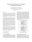
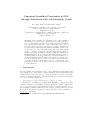
Capturing Quantified Constraints in FOL,
through Interaction with a Relationship Graph
Peter M.D. Gray1 and Graham J.L. Kemp2
1
2
Department of Computing Science, University of Aberdeen,
King’s College, Aberdeen, AB24 3UE, UK
[email protected]
Department of Computing Science, Chalmers University of Technology,
SE-412 96, Göteborg, Sweden
[email protected]
Abstract. As new semantic web standards evolve to allow quantified
rules in FOL, we need new ways to capture them from end users. We show
how to do this against a graphic view of entities and their relationships
(not just their subclasses). Some of these relationships can be derived
from data values by algebraic expressions. For example scientists may
use ad hoc lists of numbers instead of SQL key-matching conventions, as
we show in the case of molecular pathway data. The derived relationships
can also be included in captured constraints, which express domain semantics better. The constraints are captured as FOL and transmitted in
RDFS(XML) format. However the user unfamiliar with FOL is made to
see them as simple nested loops. This device even allows inclusion of existential quantifiers in readable fashion. The captured constraint can be
tested by generating queries to search for violations in stored data. The
constraint can then be automatically revised to exclude specific cases
picked out by the user, who is spared worries about proper syntax and
boolean connectives.
1
Introduction
As new semantic web standards evolve to allow quantified rules in First Order
Logic (FOL), we need new ways to capture them from end users, with names and
terms taken from a specific ontology or data model. We concentrate on domainspecific constraints, such as the constraint that “the age of a pupil’s teacher must
exceed 21” expressed in FOL as:
(∀p) pupil(p) ⇒ ((∀a,t) teacherof(t,p) ∧ age(t,a) ⇒ a>21)
Extensions to an XML based syntax (FOL RuleML) to capture this, with
explicit forall and exists quantifiers, are under discussion by W3C 1 . This format
is, of course, intended for exchanging rules between computer systems, not for
direct human readability. What we need is a way to generate them, by a sound
theory, from a declarative and more readable expression of the constraints, e.g.
for the above constraint:
1
http://www.w3.org/Submission/2005/SUBM-FOL-RuleML-20050411/
constrain each p in pupil
so that each t in teacherof(p) has age(t) > 21;
Note that the functional form teacherof(p) would be written as p.teacherof
in Java or SQL. However, such variations in syntax can easily be changed to
suit end-user preference. As long as the syntax has mathematical simplicity
matching FOL, and expressions that satisfy the syntactic parse go on to generate
valid equivalent FOL, without failing in cases that need complex computergenerated explanations, then any such syntax will suffice. Remember, it is just
an intermediate step to a well formed expression in XML that can be sent to
remote computers, checked and transformed automatically for use with other
rulebases.
An implemented language that does this is described in [9] based on a modified version of the constraint language CoLan [4]. It was originally used to
generate active rules, making a very efficient check that insertions and deletions
would not violate the constraint; such rules would be hard for a user to hand
code, especially where other rules might interact. It was subsequently used in the
KRAFT project [11], to compose constraints used in design with other smallprint constraints extracted from product databases. Thus it was convenient to
experiment with, because of its well tested software routines, but not essential.
A great deal of research has gone into sound and efficient integrity checking
mechanisms, also on algorithms to check if sets of constraints are satisfiable.
Some work has gone into formal constraint specification languages based on
FOL [18, 16, 19], but very little on how to help an end user capture a complex
constraint in this kind of unfamiliar language. Note that we are not concerned
just with simple constraints that can be captured easily by filling slots in forms,
or columns in tables, since they usually refer just to the range bounds for a
single attribute, e.g. “the age of a pupil must be between 12 and 17”. Instead,
we consider complex constraints, which may have several named attributes and
variables with different quantifiers, for example: each guidance teacher over 30
must be assigned at least one pupil. This constraint uses entities of the types
teacher and pupil, but uses an existential quantifier exists at least one for the pupil
instead of the universal quantifier for each used with teacher. These differences
are subtle, and require a background in predicate logic in order to spot them.
Natural language programs are not yet good at recognising them and their many
different equivalents.
Because of the key role of entity types (like teacher), which are connected
to other entity types through relationships or associations (like be assigned), we
needed to build an interactive graphical user interface to help an end user to
visualise the entities and relationships involved. This relationship graph gave us
something on which the user could point and click, and build up the constraint
through well-formed intermediates, so that they could not possibly enter a constraint that used terms outside the ontology, or that would fail a syntax check
or type check.
This overcomes a problem that often fatally discourages end-users of a formal
language; they write something that looks plausible but the machine rejects it
with a confusing comment. They then feel frustrated, and give up. Instead,
we display the well-formed constraint so that the user can feel satisfied with
what they have captured. We even provide the means, described later, to test it
against data. Some might argue that the real challenge for KA is to discover the
constraint from data by Machine Learning. However, this is very hard for such
complex constraints, and we need to bear in mind that scientists often have rich
background knowledge about their data, and its experimental conditions, that
may not be illustrated in the sample data. Thus it is worth providing a means
to help them capture it in a form unfamiliar to them, which we require to be
mathematically manipulable and web compatible.
We believe this use of a relationship graph is crucial to capturing complex
FOL constraints. Its use in database schema design is of course well known,
since over 30 years ago. More recently it is used in the well known UML Class
Diagram, where it has been extended to include entity subclasses and cardinality
information, just as we have it. Also UML includes applicable OO method names,
where we have derived functions, used for a slightly different purpose. Now, just
because the graph has been used so widely, it should not be considered trite.
Instead it should be acknowledged as a proven basis for capturing descriptions
of real world data, considered essential by data curators and analysts alike.
We had already pioneered using a relationship graph in a previous interactive
query builder [10]. However, it was initially unclear how to present FOL visually
to the user, and how to deal with the features of existential quantifiers. Further,
for any captured constraint, we needed also to create a query that would compute
the set of combinations of instances that violated it (hopefully empty). Here, as
we show later, the use of well-formed set expressions and boolean connectives
with quantifiers made this straightforward and sound. If we had used a language
looking more like SQL we would have come up against many hard syntactic
oddities and special cases, besides working at a low symbolic level instead of the
higher (data format independent) knowledge level.
In addition to relationships that are stored in the database, the interface
shows derived relationships on an entity-relationship diagram and enables the
user to formulate constraints involving these. We demonstrate this with examples
based on the Biomolecular Interaction Network Database (BIND) [3]. BIND
contains data about biomolecular interactions, complexes and pathways. In an
earlier project [13] we generated a functional data model (FDM) schema from the
BIND XML DTD files semi-automatically, then we loaded data into a database
using this schema, direct from the XML data instance files provided by the
BIND project. These XML files had themselves been generated automatically
from (non-relational, unnormalised) flat files specified in ASN.1 [7].
Many relationships between entity sets in the BIND database are not declared explicitly in the XML DTD file, but they can be inferred by someone who
is familiar with the contents of the database by matching stored identifier values
that act as implicit foreign keys. These relationships cannot be captured automatically by our program that reads the XML DTD file and generates a database
schema and an ER diagram from the DTD. However, they can be modelled as
derived relationships. These relationships will then appear on the ER diagram
and crucially, as seen in section 2, they can be used when capturing constraints
from users.
To illustrate this point, the DTD does not specify an explict relationship
between BIND Pathway and BIND Interaction. However, an expert will know
that the attribute pathway, which is defined on the class BIND Pathway, has as
its value a set of integers that are the identifiers of molecular interactions that
occur in the given biochemical pathway. For example, the value of this attribute
for the “epidermal growth factor” pathway is {116, 118, 145, 148, 167, 1444,
1448, 1451} where these integers are the identifiers, i.e. the iids, of instances
of BIND Interaction. This attribute can be used to define a function relating
pathway objects p to sets of interaction objects i:
define pathway_interactions(p in BIND_Pathway) ->> BIND_Interaction
i in BIND_Interaction such that iid(i) in pathway(p);
This derived relationship is shown as the labelled arc pathway interactions in
the diagram in Figure 1. Without such arcs, we would lack natural paths along
which to navigate and form constraints with an obvious meaning. Many of the
other relationships in Figure 1 are also derived, including pathway objects and
object interactions, which are defined as follows:
define pathway_objects(p in BIND_Pathway) ->> BIND_object
interaction_objects(pathway_interactions(p));
define object_interactions(o in BIND_object) ->> BIND_Interaction
(ax_inv(o) union bx_inv(o));
This illustrates the mathematical richness of the set operations used in defining
the derived functions; they are taken from a real case.
The design principles of our interactive graphical interface and its use in
formulating universally quantified constraints are described in section 2. Its extension to support existential quantifiers is described in section 3. The classes of
constraints that can be generated using the interface are summarised in section
4. Related work involving visualisation and capture of integrity constraints is
discussed in section 5 and the contributions of this paper are summarised in
section 6.
2
2.1
Design Approach
Key principles
The constraints are built incrementally using a major extension of a previous
query builder [10] and continuing to use its two essential principles, which are
widely applicable. The first was to have both a graphical depiction of the data
model, in the style of an ER diagram or UML Class diagram, and an expanding
textual description of the query, which was hyperlinked to the ER diagram,
Fig. 1. Part of the BIND schema as an ER diagram. Thick arrows connect entity types
to their subclasses. Labelled arcs show stored or derived relationships.
as shown in Figure 1. This diagram is generated directly from textual schema
declarations, and the user can drag the entities to get the diagram looking how
they want. Some designers [15] have tried to stay entirely in the graphic world,
by adding to the diagram extra graphic symbols that represent the query. Other
designers [2] stay entirely in the text world, by adding menus to the text window
which list a choice of names. Instead we keep both text and graphic windows
on screen, and make it easy to move between them. At any one time there is
a particular entity type which is the current focus of attention in the diagram,
which is shown highlighted, and correspondingly in the text window a line of the
query referring to that entity type, is highlighted. One can click on either.
The second principle was to build the query incrementally, with opportunities
to inspect intermediate results. Typically, a step involves adding a line to the
query that brings in another variable ranging over a related entity type. This
can only be done by following a relationship arc starting from the current entity
type in the ER diagram. This is just like adding an extra variable to the FROM
clause in an SQL query. However, we make the user choose the relationship by
clicking on the arc in the ER diagram. We believe this is crucial for a proper
understanding of data semantics, whereas many frame-based systems (such as
Protégé) do not distinguish relationships from other named attributes. One can
even distinguish two or more different relationships defined between the same
pair of entity types. One can also choose to make another variable range over an
entity used previously. All this is necessary for proper semantic data modelling,
as discussed in database texts. The ability to introduce derived relationships
based on a predicate value calculated from properties of the two entity instances
(e.g.qty(E1)+2 in sizes(E2)), and to represent them as arcs in the ER diagram,
is crucial to this way of working and vital to many bioinformatics databases in
order to capture the semantics correctly. It is a major focus of this paper.
The user may also extend the current query line with a restrictive filter, in the
style of a WHERE clause in SQL. This is then repeated (adding another variable
or a filter) but one can also undo a recent step. In practice the pattern is often
to add another variable, see what results one gets, and then to add filter clauses
to reduce the number of results and so focus on the likely answer. Independent
of this, at any stage, one can choose to print extra (or fewer) attributes of any
of the variables in the query so far. This adds extra columns to the result table.
Thus, at every stage, the user is sure that the query or constraint they have so
far generated is syntactically correct, and refers to items named in the ontology.
Finally, the constraint (such as that in the bottom window of Figure 1) can be
tested against data in a database, looking for any counterexamples, as shown in
Figure 2.
2.2
Basic constraint design
The basic form of constraint that we are trying to capture is essentially a formula
of first order logic, quantified over all variables, where each variable ranges over
a finite set of instances stored in a database or the facts of a knowledge base. It
is thus range-restricted. Consider the following example:
The pid assigned to a BIND Pathway must have a higher value than any of
the iid values of the BIND Interactions that make up that pathway.
(∀B0) BIND Pathway(B0) ⇒
(∀B1,P,I) pathway interactions(B0,B1) ∧ pid(B0,P)∧ iid( B1,I) ⇒ P>I
In our formal constraint language CoLan, this is rendered as:
constrain each B0 in BIND_Pathway
each B1 in pathway_interactions(B0) to have pid(B0) > iid(B1)
This is really just syntactic sugar, using to have as an implication, with unary
functions in place of binary relational predicates, and entity class names instead
of unary predicates. However, the nested indented style suggests nested loops to
programmers and scientists. It thus makes it easier to relate to a nested query,
as used in the earlier query generator.
In our experience, most universally quantified constraints used in practice
have this form, with one or more quantifiers, each range-restricted with possibly
further value restrictions on the attributes, terminating in an implication on the
last line. This line is a boolean expression (conjunction or disjunction) of truth
values. These boolean values can be formed as follows:
– a comparison of an attribute of an entity named in an outer loop with a
constant (or another attribute value);
– likewise, but a comparison with a simple arithmetic expression such as
age(j) − 1 or height(x)div2;
– a comparison of a variable representing an integer used in a loop with an
integer constant or integer attribute value or integer arithmetic expression;
for example i < chainlength(c) −1.
– a set-inclusion test relating an attribute value to a list of constants; for
example name(a) in {“pat”,“jim”,“fred”}.
– a subset-membership test to check if a variable ranging over an entity class
falls within a given named subclass, for example j isa overseas student.
2.3
Adding an Insist clause
In order to adapt the query generator to generate a constraint, (which is just a
query delivering an invariant True value), we added an extra user action through
the Insist button. This generates a line with the keyword insist followed by an
empty box, which will specify the constrained expression to be held true. The
user then clicks on this box to bring up an expression builder, which helps build
a boolean expression to replace the box. Menus ensure that only known variables
and ontology items can be used in this process. Thus the only items that are
keyed in are integer and string constants, and these are type-checked. At any
time subsequently this builder can be used as an editor to revise the expression.
The end result for the earlier example would be:
for each B0 in BIND_Pathway
for each B1 in BIND_Interaction such that
B1 in pathway_interactions(B0)
insist pid(B0)>iid(B1)
print(pid(B0),iid(B1));
The keyword insist captures the intention that, for the set of values of B0
and B1 selected by the enclosing loops, the boolean expression following insist
has to be true. This distinguishes it from a query and is easier for most users
to understand than an implication in FOL. Note that we explicitly generate the
entity type for each variable (e.g. B1 in BIND Interaction) in order to have
a hyperlink relating it to the ER diagram. The language type checker did not
need it where it could infer it from the relationship declaration.
When the user is happy with the constraint, they can press the Submit button. This generates a query to find any counterexamples to the constraint, listing
these in a separate ‘results’ window (Figure 2). Here the form of query makes it
very easy to generate by just negating the boolean expression and conjoining it
as an extra filter. This is the power of using a declarative constraint language
based on expressions with functions which can be manipulated algebraically. We
must emphasise that our implementation allows us to evaluate these efficiently
against large databases [11]. It is a different approach from those who do not
have suitable test data available and thus try to validate captured constrains
by proofs or type subsumption. In the above example our generated test query
would be:
for each B0 in BIND_Pathway
for each B1 in BIND_Interaction such that
B1 in pathway_interactions(B0) and not(pid(B0)>iid(B1))
print(pid(B0),iid(B1));
We now see the significance of the print statement, which otherwise looks
redundant. It is there to print information on the counterexamples. The constraint can be revised using the built-in query editor facilities. Finally, when the
result window shows there are no counterexamples, a Write Constraint button
is enabled which the user can press in order to capture and save the constraint
in CoLan and XML form.
Fig. 2. Response window showing constraint exceptions
2.4
Using the copy-and-paste facility
One very attractive feature of the original editor design [10] was the ability to
highlight values in the result window and have them pasted back into the query
text window as extra conditions on the loop variables. Typical counterexamples
are shown in Figure 2. Thus, for example, if results show that a constraint is
not satisfied when values in the column for attribute short label of loop variable
B1 are “GTP” or “ATP”, then one can highlight these values all in the same
result column, click Copy, revert to the text window and press the Paste button.
In the context of a constraint, this automatically adds the following negated
disjunction of conditions onto the appropriate line:
for each B1 in BIND_object such that ...
... and not((short_label(B1)="GTP") or
(short_label(B1)="ATP"))
One or more values can be highlighted in the same column, and need not be
contiguous. To generate a negated conjunction of conditions, one just highlights
one or more values in the same row, e.g.:
for each B0 in BIND_Pathway
for each B1 in BIND_object such that ...
... and not((pid(B0)=13042) and
(short_label(B1)="GTP"))
This feature is particularly valuable for end users not used to the mathematical
structure of boolean expressions. Effectively they are controlling a rudimentary
form of case-based adaptation. If left to themselves with a text editor they
tend to produce phrases from natural language such as (pid(B0)=13042 or
xxa or bcd)! Users can read properly formed expressions but may be unsure
how to write them, and are grateful to have them generated by simply clicking
on selected values. This also eliminates transcription errors, particularly when
there are long integers or unusual strings. Often, scientific users have only an
approximate memory of a value they wish to use, but they recognise it when
they see it in a result table.
The design advantages of the Insist construct now become clearer. It conforms closely enough to the query syntax to enable us to reuse proven query
editing facilities with the new construct. The end user can continue to use the
natural strategy of incremental edit, then retry, feeding back result values from
the result window as needed.
3
Dealing with existential constraints
The next challenge is to include existential quantifiers. This is not easy if you
allow them to figure in nested conditions on the left hand side of an implication, because the meaning of such complex bracketed expressions is altered
by implied negations, and this makes them unintuitive. However it is relatively
straightforward to deal with them on the right hand side of an implication, where
fortunately they most often occur.
Consider the following constraint:
Each Molecular Complex must be related through a BIND object to interactions on its interaction list.
(∀B0) Molecular Complex(B0) ⇒
(∀B1) complex objects(B0,B1) ⇒
((∃B2,I,L) object interactions(B1,B2)
∧ iid(B2,I) ∧ interaction list(B0,L)
∧ I in L)
Following the approach of the insist construct, we define an insist exist construct which introduces an existentially quantified variable ranging over an entity
type followed by such that specifying the relationship and (optionally) a boolean
expression as used in the insist construct. We can then build the above constraint
as:
for each B0 in BIND_Molecular_Complex
for each B1 in BIND_object such that
B1 in complex_objects(B0)
insist exist B2 in BIND_Interaction
such that B2 in object_interactions(B1)
and iid(B2) in interaction_list(B0);
We can easily extend this to several enclosing levels of for each. The insist
exist construct introduces the last and innermost variable in the constraint (B2
in this case). This variable has to be connected by some relationship arc to
one of the earlier variables (here B1 or B0). This differentiates it from the insist
construct, where we do not introduce another variable. Likewise we have no need
to follow it by a plain insist construct, since we can say all we want in a single
boolean expression. We thus introduce an Insist Exist button beside the Insist
button. They are like radio buttons in that pressing one inhibits the other. Thus,
if we click on a relationship arc when the Insist Exist button is pressed, then
the insist exist line is generated instead of another for each line. This line
includes an empty boolean expression box as for the insist construct; clicking
on it brings up the expression builder (although an empty box is allowed as a
special case).
Once again, we can algebraically manipulate the constraint to generate a
query searching for counter examples:
for each ...
...
for each e1 in entity such that ... and
(no e in entity such that
e in rel(e1) and (<predicate>)
exists)
print(...);
Because standard boolean algebra is being used, this still works correctly even
when <predicate> includes several combinations of and and or inserted by copy
and paste (as described above).
3.1
Inheritance of relationships
We can also apply this to classes with relationships inherited from superclasses.
This is an important generalisation of our modelling methodology, with a nice
graphical visualisation. In Figure 1 we see a superclass BIND CoreObj of three
of the main classes (BIND Pathway, etc.). When BIND Pathway is the focus
of attention, not only are its own relationships highlighted as possible ways to
extend the constraint, but so are relationships (division and updates) inherited
via the superclass. When we click on these relationship arcs they behave as if
connected to BIND Pathway itself, because it is a highlighted subclass. Thus we
can generate:
constrain each B0 in BIND_Pathway
each B1 in BIND_Rec_coll_descr such that B1 in division(B0)
to have descr(B1) <> "";
4
Classes of constraints generated
The CoLan constraint expression definition language [11] has a fully recursive
syntax summarised in the Appendix.2
The constraint generator currently expresses a subset of this, going to a
limited depth, to keep it simple for the end user. It covers all the operators
and examples in section 2.2. Currently, for simplicity both of implementation
and user understanding, the query generator will not capture constraints with
quantifiers inside a bracketed term on the left side of an implication. Thus it
must be easily transformable to prenex form, simply by moving all quantifiers
in sequence to the front. An existential quantifier, if present, will be innermost
and we could easily extend this to several existential quantifiers. We considered
allowing universal quantifiers within the existentials, but have not so far had the
need and it would make the generation of equivalent SQL much more tricky.
One of our design aims, from early experience, was to eliminate the need for
a user to key in brackets, partly because this might change expression meaning
in subtle ways, and also because it might need extra levels of sub-expression
builder which are confusing. Consequently, the arguments of functions, or of
comparisons, may include simple arithmetic expressions, but they must have an
unbracketed sequence of terms separated by + or − operators. Likewise these
terms may include unbracketed ∗ or / operators. More complex formulae are
rare, and can be handled by keying in a formula as a derived function, which
becomes part of a library. Note that the constraint may include any number
of conjunctions, and these may join well formed bracketed terms (generated by
2
Full CoLan syntax at http://www.csd.abdn.ac.uk/∼pfdm/colan syntax.html
copy and paste) which include or operators, and thus the resulting FOL need
not be a Horn clause.
5
Discussion and related work
Although GUI builders for SQL are quite common, it is very unusual to see
them related to an ER diagram. Instead, the user often chooses to display one
in another window (or may refer to a paper copy). Other GUI builders [2] often
display a dynamically generated menu of selected entity or attribute names, but
direct use of the ER diagram gives a much better understanding. This is because
it gives a direct visualisation of relationships (associations in UML) as lines in
the diagram. In building complex quantified constraints, relationships are crucial
because they are the glue that links the different entity variables together. In
our GUI builder this is made obvious, because in order to introduce an extra
line in the constraint with an associated variable quantified over an entity type,
you have to find an arc relating that entity type in the diagram to one you have
used on one of the preceding lines.3
The GUI can also capture constraints where some Variables range over subranges of Integers, defined by numerical expressions (which may include constants or functions of enclosing variables). These Integer Variables are used in
inner loops, as parameters or in conditions. Currently Integer Variables cannot
be governed by Existential Quantifiers (but this case could easily be added).
Now that we can capture rich quantified constraints on Subclasses, we have
the potential to treat these as subclass definitions and write them out in equivalent OWL description logic notation. OWL is increasingly used on the Semantic
Web and we need to pursue this.
We do not have space to describe the full power of the Functional Data Model
to define derived relationships or functions [13]; these look just like stored attributes or relationships on the ER diagram and they can be used inside constraints (e.g. complex objects in the BIND examples). They make it relatively
easy to work with functions computing distances, or angles or average areas, that
are needed to express constraints on spatial data. For example one can imagine
capturing a constraint on lines bounding regions:
for each R in Region
for each L in lines_bounding(R)
insist exist L1 in lines_bounding(R)
such that end(L) = start(L1) and
distance(end(L1),start(L)) < 100;
The function definitions are declarative, like equations. The method described
extends to a very wide range of databases accessible, for example, through JDBC
3
It is possible to introduce an entity variable joined by an inequality to another attribute value (corresponding to a theta-join in Codd’s Relational Algebra); although
this is a rare situation our system does allow it.
and PHP commands that run remotely, or from text files. All that is needed are
wrappers to convert the constraints from their textual or XML (RDFS) form
to one suiting the platform. This is a well established web architecture and we
demonstrate it for our language in [20].
Cardinality constraints have long been depicted on ER diagrams, and participation constraints on relationships and subclasses can be displayed in extended
conceptual entity-relationship diagrams as shown in[6]. Although Colan can express this by e.g. constrain at most 2 x in D to ... we do not yet include such
quantifiers in our GUI.
Recently the developers of the Protégé-2000 system [17] have introduced
a Protégé Axiom Language (PAL) also based on Predicate Logic, and using
their frame-based data model. Recent papers show how it can be used to check
consistency of the Gene Ontology [19] and medical terminology [1]. It is with
the arrival of such systems as Protégé and FOL RuleML that there will come a
need to formulate and test increasingly complex constraints. Currently Protégé
has neither a GUI builder for PAL, nor any means to query an instance of the
knowledge base for counterexamples, such as we provide.
The PROGRES visual programming language has been used to support
graphical specification of integrity constraints [15]. In that work the user draws
out the graph showing relationships between universally quantified variables representing instances of entity sets in the “for-part” of the graphical representation
of the constraint. This graph is copied into the “ensure-part” of the graphical
constraint and the user can add further relationship arcs to nodes representing
existentially quantified instance variables over entity sets. Instead, our interface
shows the data model as an ER diagram but the structure of individual constraints is shown in a separate hyperlinked text window, which allows richer
variety and interlinking.
6
Conclusions
Recent developments, such as FOL RuleML and Protégé PAL, allow rules in
FOL to be transformed and interchanged between different intelligent systems
on the Semantic Web. We believe that capturing complex domain-specific constraints as rules requires the user to be able to relate them to a diagram showing
relationships as well as subtypes, to build them in stages (with the option to
undo edits) and to be able to express quantifiers in a simple consistent fashion, as used in FOL. Thus we need graphic aids to help experts, particularly
scientists; we cannot routinely learn such rules from often incomplete data.
We have shown a systematic and novel way to do this, by using an analogy
with the familiar concept of nested loops, which makes a visual correspondence
between quantifiers and relationships in the ER diagram. This has been implemented and tested and made available.4 It includes the option at each stage to
run the embryo constraint against suitable data in remote databases and find
4
software downloadable from http://www.csd.abdn.ac.uk/∼pgray/
counterexamples. Values from these can then be fed back by copy-and-paste to
make the constraint more specific. This is particularly valuable since it helps the
user to understand the data better as they develop constraints.
A novel feature is that they can incorporate derived relationships, expressed
as well-formed algebraic formulae; these are powerful enough to capture geometrical relationships in spatial databases, and implicit relationships given by
identifier lists used in bioinformatics databases. This is vital for capturing rich
data semantics.
We have transformation programs that can take the output and turn it into
an XML form, using RDF and RDFS constructs which are becoming widely
known [12]. The RDFS constructs completely capture the constructs of the ER
diagram. The system we have described, and its design, are applicable across a
range of data storage systems. This is because we use the Entity-Relationship
model directly, without specifying any particular storage representation such as
tables, arrays or Java Classes. Nor do we include any program code, such as
SQL methods; instead we give a quantified formula in First Order Logic, which
can be mathematically transformed and combined with other formulae [11], and
transmitted in XML using RDFS/SWRL constructs. This is the basis of our
CIF Constraint Interchange Format [12, 14] and we have tested it in a variety
of applications. Now we look forward to adapting it to fit evolving standards of
W3C RIF Rule Interchange group 5 , which has very similar aims.
Acknowledgements
The constraint generator was expanded from the Java original of Ignacio Gil [10],
using the Jasper interface to Prolog on PC provided by SICStus. The Prolog software was developed originally by the P/FDM group at Aberdeen with funding
from EPSRC and BBSRC. Related work [2, 14, 20] at Aberdeen is also supported
by EPSRC (GR/N15764) under the Advanced Knowledge Technologies (AKT)
Collaboration. The schema for the BIND database was generated by Selpi working at Chalmers with Graham Kemp, and populated by her from XML files. We
are very grateful for her help in loading more data and making schema extensions
for this paper.
References
1. A. Abu-Hanna, R. Cornet, N. de Keizer, M. Crubézy, and Tu S. PROTÉGÉ as
a vehicle for developing medical terminology systems. Int. J. Human-Computer
Studies, 62:639–663, 2005.
2. S. Ajit, D. Sleeman, D.W. Fowler, and D. Knott. ConEditor: Tool to Input and
Maintain Constraints. In E. Motta, N. Shadbolt, A. Stutt, and N. Gibbins, editors, Engineering Knowledge in the Age of the Semantic Web, 14th International
Conference, EKAW 2004, Whittlebury Hall, UK, October 5-8, 2004, Proceedings,
volume 3257 of LNCS, pages 466–468. Springer, 2004.
5
http://www.w3.org/2005/rules/wg/wiki/Rulesystem Arrangement Framework
3. G.D. Bader, D. Betel, and C.W.V. Hogue. BIND: the Biomolecular Interaction
Network Database. Nucleic Acids Research, 31:248–250, 2003.
4. N. Bassiliades and P.M.D. Gray. CoLan: A Functional Constraint Language and
its Implementation. Data Knowl. Eng., 14(3):203–249, 1995.
5. F. Bry, N. Eisinger, H. Schütz, and S. Torge. SIC: Satisfiability Checking for
Integrity Constraints. In P. Fraternali, U. Geske, C. Ruiz, and D. Seipel, editors,
Proceedings of the 6th International Workshop on Deductive Databases and Logic
Programming (DDLP’98), pages 25–36, 1998.
6. B. D. Czejdo, R. Elmazri, M. Rusinkiewicz, and D. E. Embley. A Graphical Data
Manipulation Language for an Extended Entity-Relationship Model. IEEE Computer, 23:26–36, 1990.
7. O. Dubuisson. ASN.I Communication Between Heterogeneous Systems. Morgan
Kaufmann Publishers, 2000.
8. S.M. Embury. A Formal Semantics for the Daplex Language. Technical Report AUCS/TR9504, University of Aberdeen, U.K. AB24 3UE, October 1995. see
http://www.csd.abdn.ac.uk/∼pfdm/postscript/embury.1995b.ps.
9. S.M. Embury and P.M.D. Gray. Compiling a Declarative High-Level Language
for Semantic Integrity Constraints. In R. Meersman and L. Mark, editors, DS-6,
volume 74 of IFIP Conference Proceedings, pages 188–226. Chapman & Hall, 1995.
10. I. Gil, P.M.D. Gray, and G.J.L. Kemp. A Visual Interface and Navigator for the
P/FDM Object Database. In N.W. Paton and T. Griffiths, editors, Proceedings of
User Interfaces to Data Intensive Systems (UIDIS’99), pages 54–63. IEEE Computer Society Press, 1999.
11. P.M.D. Gray, S.M. Embury, K.Y. Hui, and G.J.L. Kemp. The Evolving Role of
Constraints in the Functional Data Model. J. Intelligent Information Systems,
12:113–137, 1999.
12. P.M.D. Gray, K. Hui, and A.D. Preece. An Expressive Constraint Language for
Semantic Web Applications. In A. Preece and D. O’Leary, editors, E-Business
and the Intelligent Web: Papers from the IJCAI-01 Workshop, pages 46–53. AAAI
Press, 2001.
13. G.J.L. Kemp and Selpi. Pathway and Protein Interaction Data: from XML to
FDM Database. In E. Rahm, editor, Data Integration in the Life Sciences, First
International Workshop, DILS 2004, Proceedings, volume 2994 of LNCS, pages
212–219. Springer, 2004.
14. C. McKenzie, P.M.D. Gray, and A.D. Preece. Extending SWRL to Express FullyQuantified Constraints. In G. Antoniou and H. Boley, editors, Rules and Rule
Markup Languages for the Semantic Web: Third International Workshop, RuleML
2004, Hiroshima, Japan, November 8, 2004. Proceedings, volume 3323 of LNCS,
pages 139–154. Springer, 2004.
15. M. Münch, A. Schürr, and A.J. Winter. Integrity Constraints in the Multiparadigm Language PROGRES. In H. Ehrig, G. Engels, H.-J. Kreowski, and
G. Rozenberg, editors, Theory and Application of Graph Transformations, 6th International Workshop, TAGT’98, volume 1764 of LNCS, pages 338–351. Springer,
2000.
16. J.-M. Nicolas. Logic for Improving Integrity Checking in Relational Data Bases.
Acta Inf., 18:227–253, 1982.
17. N.F. Noy, R.W. Fergerson, and M.A. Musen. The Knowledge Model of Protégé2000: Combining Interoperability and Flexibility. In R. Dieng and O. Corby, editors, Knowledge Acquisition, Modeling and Management, EKAW 2000 Proceedings,
volume 1937 of LNCS, pages 17–32. Springer, 2000.
18. S.D. Urban. ALICE: An Assertion Language for Integrity Constraint Expression.
In Proceedings of the Thirteenth International Annual Computer Software and Applications Conference, Orlando, Florida, pages 292–299, September 1989.
19. I. Yeh, P.D. Karp, N.F. Noy, and R.B. Altman. Knowledge acquisition, consistency checking and concurrency control for Gene Ontology (GO). Bioinformatics,
19(2):241–248, 2003.
20. Kit ying Hui, Stuart Chalmers, Peter M. D. Gray, and Alun D. Preece. Experience in using rdf in agent-mediated knowledge architectures. In Ludger van
Elst, Virginia Dignum, and Andreas Abecker, editors, Agent Mediated Knowledge
Management, International Symposium AMKM 2003, Stanford, CA, USA, March
24-26, 2003, volume 2926 of LNCS, pages 177–192. Springer, 2004.
APPENDIX: CoLan Syntax
In our constraint language, constraint specifications consist of two parts: a quantification part and an (optional) predicate part. The essential syntactic constructs which are required to define constraints in CoLan are given below in
BNF [9]:
<constraint dec>
<quant part>
<quant rest>
<exists>
::=
|
::=
::=
|
|
::=
constrain <quant part> <to have> <predicate> ;
constrain <quant part> <exists> ;
<quantifier> <named set expr> <quant rest>
so that <quant part>
<quant part>
[ ]
exists | to exist | [ ]
Here, <quantifier>, <named set expr>, <predicate> and <to have> and the
other non-terminals are defined by the existing Daplex language (the full syntax
of which is given in URL http://www.csd.abdn.ac.uk/∼pfdm/
user manual/user manual.html ):
<quantifier>
::=
|
|
<range quantifier> ::=
<named set expr>
::=
<predicate>
<bool term>
<bool fac>
<bool prim>
<to have>
::=
::=
::=
::=
|
|
|
|
::=
each | all | some | any | no
exactly <const>
at <range quantifier> <const>
least | most
<varid> in <set>
[such that <predicate>] [as <typeid>]
<bool term> | <predicate> or <bool term>
<bool fac> | <bool term> and <bool fac>
[not] <bool prim>
<comparison>
<quantified expr>
<set membership>
<subclass membership>
( <predicate> )
has | have | to have