1
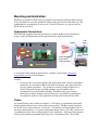
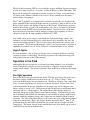
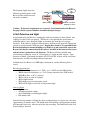
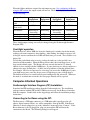
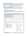
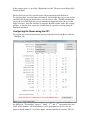
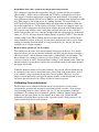
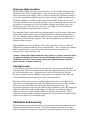
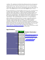
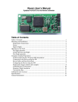
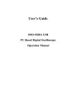
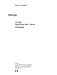
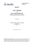
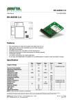
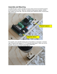
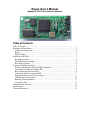
Raven User’s Manual
Updated 6/1/2012 for the Raven3 altimeter
Table of Contents
Table of Contents................................................................................................................ 1
Mounting and Installation:.................................................................................................. 2
Deployment Connections:............................................................................................... 2
Power: ............................................................................................................................. 2
High G flights: ................................................................................................................ 3
Operation in the Field ......................................................................................................... 3
Pre-flight operation ......................................................................................................... 3
Liftoff Detection and flight............................................................................................. 4
Post-flight operation........................................................................................................ 5
Computer-Attached Operations .......................................................................................... 5
Featherweight Interface Program (FIP) Installation: ...................................................... 5
Connecting to the Raven using the FIP: ......................................................................... 5
Raven Status and Data Download................................................................................... 6
Configuring the Raven using the FIP: ............................................................................ 7
Deployment triggers details and examples: .................................................................... 8
Calibrating the accelerometer: ...................................................................................... 10
Running a flight simulation .......................................................................................... 11
Viewing the data ........................................................................................................... 11
Calibration and Accuracy: ................................................................................................ 11
Specifications:................................................................................................................... 12
Contact Information:......................................................................................................... 12
Mounting and Installation:
The Raven is mounted with its long axis parallel to the direction of flight. Either end can
be up; the altimeter senses the orientation while on the pad and will work either way. The
mounting holes accommodate #2 size screws. Two #2-56 screws, two spacers and two
#2-56 nuts are provided.
Deployment Connections:
The following diagram and picture show how to connect the Raven for deployments,
using a single switch that turns on the unit and arms the deployment charges:
USB
Mini
Button
4th
Main
Apo
switch
+
3rd
o
Featherweight
Screw switch
(sold separately)
-
Battery
Capacitor
Buzzer
Deployment
A description of the default program for the 4 outputs is given in the deployment
programming section of this document.
Caution:
• Do not use this or any other altimeter for deployments until you have performed a
ground test to verify that the Raven will work correctly in your rocket and with
your pre-launch procedures. (See ground test section) Flying the Raven in a
rocket with motor ejection or another altimeter you are familiar with is
recommended for your first Raven flights. Each Raven has passed a basic
functional test before shipment, but you alone are responsible for ensuring that
your altimeter works for your application and that your rocket will fly safely.
Power:
An external battery and a switch are required. A 9V battery is recommended, but small
lithium polymer batteries have also been used successfully. The Raven can be powered
by any DC power source between 3.8 and 16 V. 9V batteries and single LiPoly cells are
the most common choices. A separate deployment charge battery, up to 20V, can be used
in combination with a lower-voltage battery for the electronics. An aerogel ultracapacitor
will keep the altimeter operational when the power is disconnected for 7-10 seconds.
The field-effect transistor (FET) used to switch the Apogee and Main deployment outputs
is rated for 9 Amps for pulses < 5 seconds, and has an Rds(on) of about 20 mOhms. The
Raven can be damaged by deployment currents in excess of 9 Amps, or by connecting a
9V battery to the altimeter with the leads reversed. Please carefully note the battery
polarity before connecting it.
The 3rd and 4th channels are recommended for airstarts, because they are designed with
larger output FETs that can handle higher current, up to about 13 Amps in the case of the
Raven 1 and 2 models, and 40Amps in the case of the Raven3. Motor airstarts typically
result in short circuits as soon as the motor ignites, so be sure to use batteries for airstarts
that cannot exceed the FET rated current when shorted. Currents in excess of 20 Amps
have not been tested and may result in damage to wiring or the connectors at a lower
current level than the 40 Amp capability of the Raven3’s FETs.
Any switch can be used as long as it can handle the deployment charge current. Our
customers love the Featherweight screw switch because of its reliability, tiny size, and
convenient mounting terminals. The screw head wipes and preloads the contacts with
every operation. The Featherweight magnetic switch is also a great option as no holes or
alignment are required to use it, and its solid-state construction makes it very reliable.
High G flights:
For extra durability, a dab of epoxy or silicone can be used under the Raven’s hold-up
capacitor to secure it to the board. The hold-up capacitor is the component wrapped in
shiny black plastic next to the USB connector.
Operation in the Field
Although the Raven is designed as an advanced recording altimeter, it can be installed
and used indefinitely without ever being connected to a computer, using the default
settings for the outputs. The following describes how the Raven is operated at the launch
range.
Pre-flight operation
Turn on the Raven using an external arm switch. The first set of beeps after power-up is
the battery voltage, rounded down to the nearest volt. (9.7 Volts = 9 beeps). After
power-on, the Raven goes into pre-launch mode. The Raven will beep a low, single beep
every 2 seconds if no charges are detected or if the accelerometer does not read a nearvertical orientation. In the case of the Raven3, the single beep will also happen if the
battery voltage is below 3.85V. The Raven will emit a high beep for each channel that is
connected and has a voltage applied. The original Raven indicated the number of
connected charges by beeping once for each connected charge. The Raven2 beeps once
for each channel, and indicates the continuity for each channel by giving a high beep for
channels with high continuity voltage, and a single beep for channels without a charge
connected. The order of the channel beeps is the same as the order of the channel outputs
along the terminal block. First is the Apogee channel, then main, then 3rd, then 4th. In
prelaunch mode, the blue LED will flash once per second, and the red light will flash
during beeps. The button, located on the terminal block side of the board, can be used to
switch between wait and prelaunch modes.
The diagram (right) shows the
different operating modes of the
Raven and the transitions from
one mode to another.
button
Power
Up
Wait
(blue flash)
button
Landed
Pre-Launch
(red flash)
(red blue flash)
Liftoff
Baro steady
(Solid Red)
Accel > 3.0 Gs &
Velocity > 3 ft/sec
Caution: If electronic deployments are expected, do not launch unless the Raven is
beeping with the expected number of connected output charges.
Liftoff Detection and flight
In prelaunch mode, the Raven is watching the axial accelerometer to detect liftoff. Any
readings less than 3.0 Gs are ignored. The Raven is also updating the accelerometer
calibration offset it uses during the flight, to maximize the accuracy of its apogee
detection. If the rocket is dropped a short distance, the Raven will ignore the subsequent
contact to avoid premature liftoff detection. Despite these features, it is possible for the
Raven to misinterpret normal handling as a liftoff, so do not arm and/or turn on the
Raven with charges connected until the rocket is installed in the launch rail or tower
and the rocket is pointed in a safe direction. The Raven will detect liftoff when
accelerometer readings in excess of 3 Gs integrate to a 3 mph upward velocity. Upon
detection of liftoff, a prelaunch data buffer of 0.352 to 0.704 seconds will be stored into
flash memory, and data recording continues from there.
In liftoff mode, the Raven’s red LED lights continuously, and the following data is
stored:
Periodic measurements:
• 400 Hz axial Accelerometer, +/- 70 Gs (or +/- 250 Gs for the 250G model)
• 200 Hz lateral Accelerometer, +/- 35 Gs (battery current for the 250G model)
• 20 Hz Baro data, +/- 0.3% accuracy
• 20 Hz voltage on each of 4 outputs
• 40 Hz output current
• 20 Hz high-precision temperature sensor
• 20 Hz for all flight events used for deployment logic.
Once per flight:
• Flight counter
• All output program settings
• Accel calibrations used during the flight
• Pad altitude ASL
After the first few minutes of flight, the data recording changes to a lower rate, and stores
approximately 35 minutes more. The liftoff mode will continue, and deployment outputs
will function if necessary, after the end of the data recording. The liftoff mode only ends
when landing is detected.
When the flight conditions assigned for each output are true, (See configuring the Raven
using the FIP section) the output switch will turn on. The default deployment conditions
are the following:
Output function
Altimeter output
Label
Upward velocity
(from accel)
Baro altitude
Altitude above pad
Time delay
Burnout Counter
Apogee
deployment
Apo
Main chute
deployment
Main
Backup apogee
deployment
3rd
Backup Main
deployment
4th
< 400 ft/sec
< 400 ft/sec
< 0 ft/sec
< 400 ft/sec
Increasing or
decreasing
Any
0
1
Decreasing
Increasing or
decreasing
Any
2 sec
1
Decreasing
< 700 feet
0
1
< 700 feet
1.5 sec
1
These default output settings can easily be changed using the Featherweight Interface
Program (FIP).
Post-flight operation
When the Raven is below 2000 feet above the launch pad, it watches for the barometric
readings to become constant to detect landing. After landing, the altitude at apogee will
be beeped out once and then the red LED will flash once per second. These features save
battery life.
To hear the peak altitude after recovery, pick up the rocket or av-bay and tilt it one
direction and then another. When the Raven detects that it has been flipped over, it will
beep out the altitude again. The Raven will beep out each decimal of a 5 decimal
altitude, in feet, starting with the 10,000 place. A pause between sets of beeps indicates a
change to the next decimal place. A short, low beep indicates a 0 in that decimal place.
For example, 1024 feet is represented as <low beep, for zero in the 10,000 place>, pause,
<one high beep> pause <one low beep> pause <2 high beeps> pause <4 high beeps>.
The button can be used to switch between post-landing mode and wait mode. Whenever
the mode is switched into wait mode, the last apogee altitude will be repeated.
Computer-Attached Operations
Featherweight Interface Program (FIP) Installation:
Download the FIP installation package from the Featherweight site. The installation
package contains both the FIP and the USB drivers necessary for the Raven to interface
with the computer. Double-click on the zip package and follow the installation package
instructions.
Connecting to the Raven using the FIP:
The Raven uses a USB-mini connector, so a USB-mini cable typically used in cell
phones, digital cameras, PDAs, etc. will be compatible. Start up the FIP. If the Raven
altimeter is already plugged in, go to the “Altimeter” menu and select “Connect.” If the
Raven altimeter is not yet plugged in, plug it in now and the FIP will detect the
connection to the Raven. The following dialog box will appear:
Select the correct altimeter model and the comm
port to which the Raven is connected. If multiple
comm ports show up in the dialog box, the
highest-numbered one will probably be the one
with the Raven connected to it.
The FIP will check to see which of the 5 flight
indexes have data in them, and will begin to provide real-time information from the
Raven, including barometric pressure (in atmospheres), accelerometer readings, and
temperature.
Raven Status and Data Download
The status tab of the FIP shows the current status of the Raven. The Flight Data box
shows the status of each of the Raven’s 5 memory banks, and which flight corresponds to
each data location.
In the example above, 4 out of the 5 flight banks are full. The most recent flight (#6) is
located in bank 3.
The live data box provides real-time status and measurements from the Raven.
To download data, select the button “Download” for the flight data you’re interested in,
and follow the dialog box instructions to save the data to a file. The FIP automatically
detects the end of the flight, but you can interrupt the download before the end of the
flight, if desired. After the download is complete, the FIP switches to the data viewing
window. A data file from a previous download can be opened for viewing using the
File/Open command.
Configuring the Raven using the FIP:
To program and verify the deployment options programmed into your Raven, click the
“Configure” tab.
The logic used for each deployment output is represented as a column of check boxes in
the dialog box. The headings “Apogee”, “Main”, “3rd” and “4th” correspond to the text
labels on the altimeter. All of the channels can be programmed to be used for any
purpose, though channels 3 and 4 have higher current capability for airstarts. The text
boxes arranged along the right side are set points that you can change, that control the
speed, altitude, etc. the altimeter will check for when deciding when to fire the output. A
deployment channel is triggered when all of the checked flight events are true. Note that
most flight events, like acceleration < 0, can switch from true to false and back again
throughout the flight. Other events, like time > user timer value, can have no more than
one transition during the flight.
The “time delay” option will delay the start of the output by the specified time delay after
all other conditions are met. Note that once the deployment conditions are met, the
deployment will happen after the time delay regardless of any changes in the deployment
conditions after the delay timer has started.
Each output will be activated for 1 second, unless the “Hold the switch closed
continuously” option is selected for that output. The continuous output option is
designed to turn on a non-deployment load, like a transmitter. This option is not
recommended for use with deployment charges because charges can have residual shorts
that could drain the pyro battery for future use and/or damage the FET switch.
Deployment triggers details and examples:
Pressure Increasing (used for the default apogee, main, and main backup deployment
channels):
This condition is true whenever the filtered baro pressure measurements are increasing.
Since pressure decreases with altitude, this trigger corresponds to when the rocket is
falling. This trigger is used for the default main deployment channel so that the ascent is
ignored for the main chute deployment. Transitions to and from supersonic flight can
cause this condition to become true temporarily during ascent. That’s why the main
deployment channel looks for an additional condition, the velocity check.
Velocity < 0 feet/second (used for the backup apogee deployment channel)
This trigger is true when the upward velocity has stopped and the rocket is starting to fall.
The Raven senses the acceleration and subtracts off what it was reading when it was
sitting on the pad (about 1 G). Then it adds up the accelerations continuously throughout
the flight to calculate the velocity. This method provides an apogee detection that is
immune to pressure anomalies, but off-vertical flights or mis-aligned altimeter can affect
the apogee detection accuracy.
Height above pad < AGL1: (used for the default main deployment channel)
This condition is true when the measured altitude above the pad is below the AGL1
setting. AGL1 can be set between 0 and 32736 feet, in increments of 32 feet. For the rest
of the main deployment settings, other conditions need to be checked, since this condition
will be true from liftoff until the rocket gets above the main deployment altitude.
Velocity < Vel1: (used for the default main deployment channel and backup channels):
This condition is true when the accelerometer-based estimate of upward velocity is lower
than Vel1. This trigger is useful in combination with the pressure increasing trigger, to
ensure that the rocket is out of the transonic region before using the pressure increasing
check. The velocity check is also a useful trigger for 2nd stage ignition. Optimal altitude
can be achieved by allowing the rocket to slow down before 2nd stage ignition, while
maintaining enough speed so that the flight path stays nearly vertical. This trigger can be
used to ignite a 2nd stage at the desired velocity, even in the event of unexpected drag or
motor performance.
Velocity > Vel2:
This condition is true when the accelerometer-based estimate of upward velocity is higher
than the Vel2 value. Vel2 can be set between -48 feet/second and 1998 feet/second, in 2
ft/second increments. This setting is one way to check to make sure that the rocket is
flying as expected before performing a high-speed sustainer ignition. If the rocket is in
the middle of a tumbling breakup, the velocity will be lower than expected
Acceleration > Accel1 and Acceleration < Accel2:
This condition is true when the accelerometer’s reading is greater than the Acc1 value or
less than the Acc2 value, respectively.
Acc1 and Acc2 can be set in the range from -50Gs to +50Gs, in increments of 0.1 Gs.
These triggers are useful for detecting staging charges, deployment charges, motor burns,
and landing events. Note that there are lots of different flight events that can cause
changes in the acceleration values, so it’s important to combine this trigger with other
conditions if used. For example, you could use this trigger to detect landing for a chute
disconnect device, by looking for acceleration greater than 3 Gs. For this application,
you would also need to prevent a premature deployment by setting the following
additional conditions for the trigger: the altitude < AGL1, pressure increasing, velocity <
Vel1 to avoid a premature deployment. New for the Raven2 (not available with the
original Raven) is a third altitude trigger that makes it easier to set up the landing
detection and the main deployment using the same altimeter (See Height Above Pad <
AGL3)
Time < user timer value and Time > user timer value:
This condition is true when the elapsed time from liftoff detection is less than, or greater
than, the user-settable timer threshold, TVal. TVal can be set from 0 to 51.2 seconds, in
0.02 second increments. The time > Tval setting can be used as a simple timer, or in
combination with other conditions to make sure that the rocket has gotten past the initial
low-altitude part of the flight. Note that liftoff detection may occur a fraction of a second
after 1st motion.
Height Above Pad > AGL2
This condition is true when the height above the pad is greater than the user-settable
altitude AGL2. AGL2 can be set between 0 and 32736 feet, in increments of 32 feet.
This trigger is useful for air start ignition of motors, as it can be combed with the time <
TVal to ensure that the rocket is on its way to a nominal flight before igniting the next
motor. For example, if a simulation predicts that the booster + sustainer should achieve
7000 feet within 6 seconds, you could set the AGL2 to 6000 feet and the Tval to 6
seconds to be assured that the sustainer won’t fire if the rocket is tumbling or has a flight
angle far from vertical. To ensure that the measured pressure won’t be affected by Mach
transition transients, you could also check to make sure that the pressure is decreasing
and the velocity is < 1000 ft/second.
Height Above Pad < AGL3 (used for the default main backup channel)
This condition is true when the height above the pad is greater than the user-settable
altitude AGL3. AGL3 can be set between 0 and 32736 feet, in increments of 32 feet.
This trigger is useful for triggering an event below the main altitude. For example, the
main deployment altitude could be set to 1000 feet, and a backup main deployment at 800
feet. This trigger is also useful as part of a landing detection. To detect landing, set
AGL3 well below the main deployment altitude but higher than the highest terrain that
the rocket might land on. Set the velocity < 0 check (so that it won’t happen on the way
up), and set the accelerometer check consistent with the direction of the landing impulse.
For a typical setup with the rocket’s main chute attached above the av-bay, look for a
positive acceleration, and use a value that is higher than the rocket might get on the main
chute (> 1.5-2 Gs), but lower than the landing impulse (typically 5-20 Gs). Note that the
default settings in the FIP for landing detection assume that the av-bay will land in the
same orientation as it has on the pad. If your rocket configuration leads to a nose-down
landing, the landing detection should be set up to look for accel < Accel2, and Accel2
should be set to a negative number.
Burnout counter (default of 1 for all outputs):
This condition is the count of the motor burnouts detected by the Raven. It is settable
between 0 (don’t wait for any burnout indication) and 1023 (not that anyone can make a
1024 stage rocket!), and the burnout count can be set individually for each output. The
Raven watches for a change in velocity of at least 40 ft/sec, and then waits for the
velocity to drop by at least 5 feet/second before adding 1 to the burnout count. When the
burnout counter is greater than or equal to the user burnout count for that output channel,
the trigger will be true.
Unlike the burnout counter used in other altimeters, this version will not mistakenly trip
if a launch rod snag or noisy motor burn causes a brief drop in the motor thrust. It also
won’t mistake a stage separation charge from a motor ignition. However, very lowimpulse airstart motor may not trigger the burnout counter, so this should only be used
for motors that will increase the velocity by 40 feet/second or greater.
Calibrating the accelerometer:
The Raven has a user-calibration function for the accelerometer to ensure correct
accelerometer operation and account for accelerometer drift over time. If the average
axial G reading in the live data is outside of 0.8 to 1.2, the accelerometer should be
recalibrated. To calibrate the accelerometer, push the “calibrate” button in the cal/test
flight tab and place the Raven on a flat surface on its short edge. Follow the FIP
instructions to hold the Raven in each of the 4 positions shown. Each position is a 90
degree rotation from the previous position.
Running a flight simulation
The Raven has a flight simulation feature that allows a realistic flight simulation to be
performed on the Raven, using the Raven’s own sensors, the current deployment logic,
and real activation of the outputs. This is useful for verifying the deployment settings, as
well as the compatibility of the Raven power source with the e-matches or igniters used.
The flight simulation is available on the cal/test tab of the FIP. Follow the on-screen
directions and button labels to perform the flight. You can control the duration of the 5G
acceleration, even turning it on and off to simulate multiple-stage flights or air-starts.
The Raven records all the data just as if it were a real flight, so you can familiarize
yourself with the Raven operation and data review.
The simulated flight assumes that the Apo output channel is used for apogee deployment,
and the Main output channel is used for main deployment. When the apogee channel
fires, the simulation applies a 100 ft/second descent rate. When the main output fires, a
descent rate of 20 feet/second is applied. The other two outputs have no effect on the
simulated flight trajectory.
Although the Raven can be mounted in your rocket with either end up, the simulated
flight must be conducted with the screw terminal block up. This is because the simulated
thrust is implemented as a test mode of the accelerometer chip that applies the
acceleration in a single direction, only
Caution: Do not run a flight simulation with e-matches or igniters connected unless
the igniters/e-matches are located away from flammable materials and adequate
ventilation is provided. In particular, do not run a flight simulation with black
powder charges or motors connected!
Viewing the data
A data file from a previous download can be opened for viewing using the File/Open
command. The default set of measurements shows the altitude above the pad in feet, and
the axial accelerometer trace. Additional traces can be added to the plot using the
Parameter selection tool bar. Multiple measurements can be plotted on the same time
scale by holding down the <control> key when selecting the traces.
The lower section of the parameter selection toolbar allows you to select flight event
logic that was recorded during the flight. The flight event logic states are the conditions
that are measured by the Raven and used in the deployment control logic. The
deployment output fires when all of the checked logic conditions are true. By plotting the
voltage on each of the outputs and the flight event logic that was checked during the
flight, you can verify exactly what the altimeter was firing, when, and why. This is
useful for verifying a flight program by looking at the data recorded in a simulated flight,
which records data just as a real flight would.
Calibration and Accuracy:
The barometric sensor used in the Raven is a digital-output sensor that contains the entire
analog measurement chain on one chip. The sensor is factory-calibrated over a wide
range of temperatures and pressures to provide exceptional accuracy under any rocketry
conditions. The combination of individual chip calibration and end-to-end temperature
compensation provides barometric accuracy that raises the bar for rocketry altimeters.
The Raven has less than 1 mbar (0.1% full-scale) pressure error over most conditions,
and less than 3 mbar pressure error (0.3%) the temperature range from -40C to 85C, and
from 1.1 Atm (2500 feet below sea level) to 0.3 Atm (30,000 feet above sea level).
Keep in mind that however accurately the Raven measures pressure, converting pressure
to altitude results in additional error. The Raven uses the International Standard
Atmosphere (ISA) model, which uses 3 different formulas for different altitude ranges
between sea level and 104,987 feet to compensate for the temperature behavior of
different parts of the atmosphere. The standard atmosphere model is implemented in the
Raven with full ANSI-C floating point calculations to avoid errors from numerical
approximations. The standard atmosphere model, however, is an approximation to
typical conditions for mid-latitude locations. It assumes a temperature profile that is
likely to be colder than typical rocketry conditions. For example, the standard
atmosphere model assumes that the sea-level temperature is 59 F, and that the
temperature at 5400 feet ASL is 40F. Errors caused by the atmosphere being warmer
than the standard atmosphere can result in reported altitudes that are low by 10% or more.
For the most accurate conversion between the pressure and altitude, use the twice-daily
balloon sounding data measured by NOAA and conveniently available at
http://weather.uwyo.edu/upperair/sounding.html. Future versions of the FIP may include
an option for automated lookup and correction based on this data.
Specifications:
Brand
Model
Axial Accel range and
frequency
Axial Accel resolution
Lateral Accel range and
frequency
Lateral Accel Resolution
Download Interface
Baro Range (kft)
Baro resolution
Pyro Outputs
Single-battery max output
Amps
2-battery max output Amps
Featherweight
Raven3
70Gs, 400Hz
0.09 Gs
35 Gs, 200 Hz
0.09 Gs
USB mini
100
0.1 mbar
4
Size
9 and 40
9 and 40
Temperature, 4
continuity
voltages, all
event logic,
battery V
480 seconds
35 minutes
0.8" x 1.8" x
0.5"
Mass
6.6 grams
Other recorded measurements
High-rate download time
Low-rate download time
Contact Information:
Email:
[email protected],
post a message at the forum at
www.featherweightaltimeters.com,
send a private message to “Adrian A”
via www.rocketryforum.com or
www.rocketryplanet.com.