1
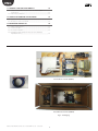
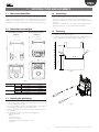
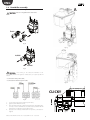
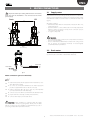
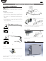
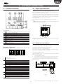
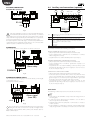
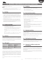
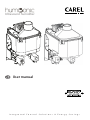
Ultrasound humidifier User manual I n t e g r a t e d C o n t r o l S o l u t i o n s & E n e r g y S a v i n g s ENG WARNINGS CAREL humidifiers are advanced products, whose operation is specified in the technical documentation supplied with the product or can be downloaded, even prior to purchase, from the website www.carel.com. Each CAREL product, in relation to its advanced level of technology, requires setup/configuration/ programming/commissioning to be able to operate in the best possible way for the specific application. The failure to complete such operations, which are required/indicated in the user manual, may cause the final product to malfunction; CAREL accepts no liability in such cases. The customer (manufacturer, developer or installer of the final equipment) accepts all liability and risk relating to the configuration of the product in order to reach the expected results in relation to the specific final installation and/or equipment. CAREL may, based on specific agreements, act as a consultant for the installation/commissioning/use of the unit, however in no case does it accept liability for the correct operation of the humidifier and the final installation if the warnings or suggestions provided in this manual or in other product technical documents are not heeded. In addition to observing the above warnings and suggestions, the following warnings must be heeded for the correct use of the product: • CAREL adopts a policy of continual development. Consequently, CAREL reserves the right to make changes and improvements to any product described in this document without prior warning. The technical specifications shown in the manual may be changed without prior warning. The liability of CAREL in relation to its products is specified in the CAREL general contract conditions, available on the website www.carel.com and/or by specific agreements with customers; specifically, to the extent where allowed by applicable legislation, in no case will CAREL, its employees or subsidiaries be liable for any lost earnings or sales, losses of data and information, costs of replacement goods or services, damage to things or people, downtime or any direct, indirect, incidental, actual, punitive, exemplary, special or consequential damage of any kind whatsoever, whether contractual, extra-contractual or due to negligence, or any other liabilities deriving from the installation, use or impossibility to use the product, even if CAREL or its subsidiaries are warned of the possibility of such damage. DISPOSAL DANGER OF ELECTRIC SHOCK The humidifier contains live electrical components. Disconnect the mains power supply before accessing inside parts or during maintenance and installation. • DANGER OF WATER LEAKS The humidifier automatically and constantly fills/drains certain quantities of water. Malfunctions in the connections or in the humidifier may cause leaks. The humidifier is made up of metal parts and plastic parts. In reference to European Union directive 2002/96/EC issued on 27 January 2003 and the related national legislation, please note that: 1. WEEE cannot be disposed of as municipal waste and such waste must be collected and disposed of separately; 2. the public or private waste collection systems defined by local legislation must be used. In addition, the equipment can be returned to the distributor at the end of its working life when buying new equipment; 3. the equipment may contain hazardous substances: the improper use or incorrect disposal of such may have negative effects on human health and on the environment; 4. the symbol (crossed-out wheeled bin) shown on the product or on the packaging and on the instruction sheet indicates that the equipment has been introduced onto the market after 13 August 2005 and that it must be disposed of separately; 5. in the event of illegal disposal of electrical and electronic waste, the penalties are specified by local waste disposal legislation. Important: • • • • • • • • • • • Environmental and power supply conditions must conform to the values specified on the product rating labels. The product is designed exclusively to humidify rooms directly. Only qualified personnel who are aware of the necessary precautions and able to perform the required operations correctly may install, operate or carry out technical service on the product. Only water with the characteristics indicated in this manual must be used for water vapour production. All operations on the product must be carried out according to the instructions provided in this manual and on the labels applied to the product. Any uses or modifications that are not authorised by the manufacturer are considered improper. CAREL declines all liability for any such unauthorised use. Do not attempt to open the humidifier in ways other than those specified in the manual. Observe the standards in force in the place where the humidifier is installed. Keep the humidifier out of the reach of children and animals. Do not install and use the product near objects that may be damaged when in contact with water (or condensate). CAREL declines all liability for direct or indirect damage following water leaks from the humidifier. Do not use corrosive chemicals, solvents or aggressive detergents to clean the inside and outside parts of the humidifier, unless specifically indicated in the user manual. Do not drop, hit or shake the humidifier, as the inside parts and the linings may be irreparably damaged. Warranty on materials: 2 years (from the date of production, excluding consumables). Approval: the quality and safety of CAREL products are guaranteed by the ISO 9001 certified design and production system, as well as by the 3 mark. “Ultrasound humidifier for fan coils” +0300056EN - rel. 1.2 - 15.01.2013 ENG Content 1. INTRODUCTION AND ASSEMBLY 1.1 1.2 1.3 1.4 1.5 1.6 Ultrasound humidifier 4 transducers .........................................................................7 Dimensions and weights...................................................................................................7 Opening the packaging ....................................................................................................7 Positioning ...............................................................................................................................7 Fastening .....................................................................................................................................7 Humidifier assembly.............................................................................................................8 2. WATER CONNECTIONS 2.1 2.2 10 Atomised water distributor ........................................................................................... 10 Fan conveyor .......................................................................................................................... 10 4. ELECTRICAL CONNECTIONS 4.1 4.2 4.3 4.4 9 Supply water .............................................................................................................................9 Drain water .................................................................................................................................9 3. ATOMISED WATER DISTRIBUTION 3.1 3.2 7 11 Electrical installation.......................................................................................................... 11 Power cable connection ................................................................................................ 11 Main board connections ............................................................................................... 11 Auxiliary card connections (optional)..................................................................... 12 5. STARTING, USER INTERFACE AND BASIC FUNCTIONS 13 5.1 5.2 5.3 5.4 5.5 5.6 5.7 5.8 5.9 Starting ...................................................................................................................................... 13 Shutdown/Standby ........................................................................................................... 13 Autotest..................................................................................................................................... 13 LED signals............................................................................................................................... 13 Disabling ................................................................................................................................... 13 Reset tank hour counter ................................................................................................. 13 Automatic washing............................................................................................................ 13 Washing due to inactivity .............................................................................................. 13 Automatic insufficient supply water management ...................................... 13 6. LCD TERMINAL (OPTIONAL) 6.1 6.2 6.3 6.4 6.5 6.6 6.7 6.8 Remote display terminal ................................................................................................. 14 Meaning of the symbols ................................................................................................. 14 Keypad ..................................................................................................................................... 14 Main display............................................................................................................................ 14 Display software release.................................................................................................. 15 Accessing and setting parameters ........................................................................... 15 Parameters: Recall default values .............................................................................. 15 Reset hour counter from display ............................................................................... 15 7. CONFIGURATION PARAMETERS 7.1 7.2 7.3 7.4 14 16 Basic parameters.................................................................................................................. 16 Advanced parameters ...................................................................................................... 16 Serial connection parameters ..................................................................................... 17 Read-only parameters ...................................................................................................... 17 8. ALARMS 19 9. MAINTENANCE AND SPARE PARTS 20 9.1 9.2 9.3 Spare parts............................................................................................................................... 20 Tank cleaning and maintenance ............................................................................... 20 Cleaning and maintenance of other components ........................................ 20 10. WIRING DIAGRAMS 21 10.1 Diagram .................................................................................................................................. 21 5 “Ultrasound humidifier for fan coils” +0300056EN - rel. 1.2 - 15.01.2013 ENG 11. GENERAL FEATURES AND MODELS 22 11.1 Ultrasound humidifier models for fan coils and electrical specifications ................................................................................................................... 22 11.2 Technical specifications................................................................................................... 22 12. HUMIDIFIER CONTROL VIA NETWORK 23 12.1 Supervisor variable list ..................................................................................................... 23 12.2 Production control via network ................................................................................ 24 13. OPERATING PRINCIPLES 13.1 13.2 13.3 13.4 25 Ultrasound atomisation................................................................................................... 25 Control principles................................................................................................................ 25 Flow-rate modulation....................................................................................................... 25 Modulazione della portata in serie (solo ver. 4 trasduttori, Dipswitch 8 a On)................................................................................................................ 26 F 2 transducers version (UU01F) 4 transducers version (UU01G) Fig.1 - Packaging “Ultrasound humidifier for fan coils” +0300056EN - rel. 1.2 - 15.01.2013 6 ENG 1. INTRODUCTION AND ASSEMBLY 1.1 Ultrasound humidifier 1.4 Positioning Ultrasound humidifiers can be used for vast variety of applications, e.g. data centers, climate rooms, close control units and food preservation, for the RH% control. The 2-transducer version (UU01F) has been specifically developed for integration into fan coils. Atomised water production is 0.5 l/h (UU01F) and 1 l/h (UU01G), delivered directly into the air stream. • The humidifier may only be accessed by specialist personnel; • make sure the humidifier is level horizontally, observing the minimum clearance of 20 mm on the sides to leave room for maintenance; • position the humidifier so as to allow the atomised water to be freely delivered; • position the transformer in a place that’s protected against possible water leaks and in any case not underneath the humidifier. 1.2 Dimensions and weights 2-transducer version (UU01F) 1.5 Fastening 4-transducer version (UU01G) Fastening instructions: 1. make two holes as shown in Fig. 1.b; 2. fix the fastening bracket using two M4x12 screws supplied (see Fig. 1.c), using a spirit level to make sure installation is horizontal; >200 mm .50 3. 3 50 92 (110) Fig. 1.b Fig. 1.a dim. mm (“) A B C weights kg (lb) packaged empty UU01F 121 (4,76) 125 (4,92) 221 (8,70) 3,9 (8,60) 2,8 (6,17) UU01G 185 (7,28) 125 (4,92) 216 (8,50) 5,5 (12,13) 4,4 (9,7) Tab. 1.a 1.3 Opening the packaging □ Make sure the humidifier is intact upon delivery and immediately notify the transporter, in writing, of any damage that may be due to careless or improper transport; □ move the humidifier to the site of installation before removing from the packaging, grasping the neck from underneath; □ open the cardboard box, remove the protective material and remove the humidifier, □ The following are contained inside the packaging (fig 1): • A: fastening bracket; • B: tank; • C: fill solenoid valve; • D: drain solenoid valve; • E: transformer (make sure voltage is correct); • F: cable kit. Fig. 1.c 7 “Ultrasound humidifier for fan coils” +0300056EN - rel. 1.2 - 15.01.2013 ENG 1.6 Humidifier assembly A Connect the valves as shown in Figure 1.d and 1.e Important: insert an o-ring before the drain valve Drain Fill Fig. 1.d Fig. 1.g CLICK!! CLICK!! Fig. 1.e Important: correct wiring of the ultrasound humidifier is the responsibility of the final appliance manufacturer, as required by IEC EN 60335-1. • Connect the valve power cable; • Connect the transformer power cable. Fig. 1.h CLICK!! ! Fig. 1.f 1. 2. 3. 4. Connect the piezoelectric element power cable; grip the tank A with two hands; place the tank vertically on the fastening structure, first aligning the connector on the tank with the electronic board, and then the fill and drain hoses with the corresponding valves; apply pressure vertically until the tank is in position, i.e. the tabs are aligned. “Ultrasound humidifier for fan coils” +0300056EN - rel. 1.2 - 15.01.2013 Fig. 1.i 8 ENG 2. WATER CONNECTIONS 2.1 Supply water Important: before proceeding with the water connections, make sure that the humidifier is not connected to the mains power supply. Drain 90 The ultrasound humidifier works on demineralised water. Using normal water will shorten transducer life; specifically, maintenance intervals for cleaning or replacing transducers depend on to what extent the supply water mineral content exceeds the values recommended in Table 11.b (pg.21). Fill Operating conditions: • demineralised water with the characteristics indicated in Table 11.b, supply water (p. 21); • pressure between 0.1 and 0.6 MPa (14.5 and 116 PSI), temperature between 1 and 40 °C (33.8 and 104 °F), G1/8 F connection (see par. 11.2 ‘Technical specifications’); • no organic compounds. 1 0 G 8' 1/ F 61 Important: 44,5 • do not add disinfectants or anticorrosive compounds to the water, as these are potential irritants; • the use of well water, industrial water or water from cooling circuits and, in general, any potentially chemically or bacteriologically contaminated water is prohibited. Fig. 2.j (bottom view) 2.2 Drain water This is not toxic and can be drained into the sewerage system. (Council Directive 91/271/EEC on Urban Waste Treatmen). water inlet water drain Fig. 2.k Water connections (parts not included): □ □ □ □ □ □ 1. Install a manual shut-off valve upstream of the installation (so as to shut off the water supply); 2. use a hose to connect the humidifier to the water supply (the product is supplied with a slide-on elbow connector); 3. install a mechanical filter (60 μS) to trap any solid impurities (connected downstream of the water tap); 4 connect a section of drain hose, minimum inside diameter 6 mm; 5 prepare a funnel to interrupt continuity in the drain line; 6 connect a drain trap to prevent bad odours. Important: When installation is completed, flush the supply hose for around 30 minutes by piping water directly into the drain, without sending it into the humidifier. This will eliminate any scale or processing residues that may block the fill valve. 9 “Ultrasound humidifier for fan coils” +0300056EN - rel. 1.2 - 15.01.2013 ENG 3. ATOMISED WATER DISTRIBUTION 3.1 Atomised water distributor Important: the atomised water delivery hose, the distributor, the fan conveyor, the elbow connection and the diffuser are not supplied with the humidifier. Requirements: • humidifier delivery hose OD 40 mm; • make sure the atomised water outlet area is 1100 mm2 (e.g. 22 holes 8 mm in diameter); • the hose running to the distributor should have a minimum upward • • • • Fig. 3.d gradient of 2° so that any condensate flows back into the humidifier or a special condensate drain system; make sure there are no condensate leaks from the water vapour distributor; position the distributor in such a way that the air is not directed against nearby objects (minimum distance 10 cm); bends or choking of the hose may cause condensate to form and decrease humidity delivery; avoid loads that may cause mechanical stress on the humidifier outlet connector. 3.1 Elbow connector 2° Fig. 3.e The elbow connector can be installed on the cover and/or the fan conveyor, so as to reduce the overall height occupied by the product. 3.2 Diffuser Fig. 3.a Fig. 3.f The diffuser can be installed on the cover, so as to deliver atomised water directly into the room. 3.3 Installation example Fan coil installation example Fig. 3.b 3.2 Fan conveyor Fig. 3.c The air flow conveyor can be installed on the top of the fan (removing the protection grill) so as to take in air from a different place to where humiSonic is installed. “Ultrasound humidifier for fan coils” +0300056EN - rel. 1.2 - 15.01.2013 Fig. 3.g 10 ENG 4. ELECTRICAL CONNECTIONS 4.1 Electrical installation 4.2 Power cable connection Board connections Correct wiring of the ultrasound humidifier is the responsibility of the final appliance manufacturer, as required by IEC EN 60335-1. Before performing the electrical connections, make sure that the unit is disconnected from the mains power supply. Check that the power supply voltage of the appliance corresponds to the value indicated on the rating plate affixed to the side of the product. Connect the transformer output cable to the electronic board (terminal block A in Fig 4.a). Connect the transformer input cable to the mains. The humidifier power line must be fitted with a disconnect switch. Note: avoid unwanted interference, the power cables should be kept separate from the probe signal cables. Main Supply Fig. 4.a Key to Fig. 4.a: A board power supply input from transformer (24/36V for 230V transformer or 24/30V for 115V transformer) B transducer power cable; C valve power cables (L drain / R fill) D configuration dipswitch E TAM (current transformer) input for measuring current on fan neutral F trimmer connection to adjust set point (optional) G TH humidity probe connection (IIC digital serial, part no.: HYHU000000) optional. M14 remote ON/OFF (M14.1-M14.2) M11 RS4845 serial (M11) M15 - N.O. alarm relay (M15.1-M15.2) - 30 Vdc output (24 Vac rectified , max. 3W) (M15.3-M15.4) N auxiliary card connection Tab. 4.b 0 Fig. 4.c Once the electrical and water connections have been completed, the humidifier is ready for operation. 4.3 Main board connections Depending on the type of signal used, atomized water production can be enabled and/or managed in different ways (ON/OFF or modulating). Dipswitch configuration: configuration must be performed HUMIDOSTAT OR REMOTE CONTACT (ON/OFF action) Production is enabled by closing terminal M14. M14 can be connected to a switch, a humidistat or a controller (voltagefree contact, max 5 Vdc open, max 7 mA closed). before fitting the tank. ON 1 2 3 4 5 6 7 36/30V 0 24V TH HUMIDITY PROBE (Optional) If the TH humidity probe is connected to the G terminal (fig 4.a) atomized water production starts ifi: • The terminal M14 is closed; • The humidity value measured by the probe is below the setpoint (preset at 50%rH and modified via dipswitches 5-6, see Tab.4.a) The setpoint can be changed by connecting the trimmer (optional) to F terminal (fig 4.a) 8 Fig. 4.b Communication OFF Serial 485 Carel/Modbus ON tLAN 2-3 tLAN address (if 1 is ON) OFF/OFF - OFF/ON address 1 ON/OFF address 2 ON/ON address 3 4 Serial 485 / tLAN baud rate OFF 19200 ON 9600 5-6 Humidity Setpoint OFF/OFF 50 %rH OFF/ON 30 %rH ON/OFF 40 %rH ON/ON 60 %rH 7 TAM OFF disabled ON enabled 8 Production transducer management (only for 4-transducer version) OFF --> parallel management (modulation of all 4) ON --> if demand is less than 50%, only one pair of transducers operates, alternately Tab. 4.c 1. M 14 Remote ON/OFF + GND Fig. 4.d 11 “Ultrasound humidifier for fan coils” +0300056EN - rel. 1.2 - 15.01.2013 ENG 4.4 Auxiliary card connections (optional) 485 SERIAL CONNECTION Carel/Modbus protocol J8 M9 1 2 + GND 21Vdc 1 2 3 4 J17 5 M 11 M10 RS 485 GND TX RX Fig. 4.e Fig. 3.a Important: for RS485 connections in household (IEC EN 55014-1) and residential (IEC EN 61000-6-3) environments, use shielded cable (with shield connected to PE both on the terminal and controller ends), maximum length specified by the EIA RS485 protocol, equivalent to European standard CCITT V11, using AWG26 twisted pair cable; the input impedance of the 485 stage is 1/8 unit-load (96 kOhm). This configuration allows a maximum of 256 devices to be connected, with cables in separate conduits from the power cable. J8 M9 M10 J17 ALARM RELAY tLAN terminal connection (optional) with 30 Vdc power supply (24 Vac rectified) tLAN AUX serial connector M10.1 - + Analogue proportional controller/probe/humid. M10.2 - + GND analogue proportional controller/probe/humid. M10.3 - +21Vdc for active probe supply M10.4 - N.U. M10.5 - N.U. AUX input The auxiliary card features the following connections This is used to signal one or more alarms via a remote connection. ON/OFF CONTROLLER (humidostat or remote switch) • jumper inputs M14.1 and M14.2 (enable) on the main board; • connect terminals M10.1 and M10.2 to a humidostat or a remote switch (voltage-free contact) • set parameter A0=0 to enable On/Off operation (see Chap. 7) M 15 EXTERNAL PROPORTIONAL CONTROLLER (modulating) • jumper inputs M14.1 and M14.2 (enable) on the main board; • connect terminals M10.1 and M10.2 (production request) to an external controller; • set parameter A0=1 to enable modulating control (see Chap. 7) and parameter A2 depending on the chosen signal (0 to 10 V, 2 to 10V, 0 to 20, 4 to 20 mA) (see Chap. 7). Alarm relay COMMON NO CONTROL WITH CAREL HUMIDITY PROBE • jumper inputs M14.1 and M14.2 (enable) on the main board; • connect the probe to terminals M10.1, M10.2. The power line M10.3 can be connected with cable of maximum lenght of 2 m (6,6 ft); for greater lenghts use an external power supply with the signal earth electrically connected to the signal earth of the controller. • set parameter A0=2 to enable probe control (see Chap. 7) and parameter A2 depending on the chosen signal (0 to 10 V, 2 to 10V, 0 to 20, 4 to 20 mA) (see Chap. 7). Fig. 4.f ALARM RELAY POWER SUPPLY The connections shown in Fig.4.g can be used to directly control a light or an auxiliary relay coil 30 Vdc (24 Vac rectified), 3 W max. M 15 Final checks The following conditions represent correct electrical connection: Alarm signal (max 3W) +24 V □ mains power to the humidifier corresponds to the voltage shown on the rating plate; □ a mains disconnect switch has been installed so as to be able to disconnect power to the humidifier; □ terminals M14.1, M14.2 are jumpered or connected to a contact to enable operation; □ if the humidifier is controlled by an external controller (with auxiliary card), the signal earth is electrically connected to the controller earth. GND Fig. 4.g Note: in industrial environments (IEC EN61000-6-2) the signal cables leaving the unit must not exceed 10 m (33 ft)(1) in length: remote on/off digital input (terminals M14.1...M14.2) and shielded cable for RS485 communication. “Ultrasound humidifier for fan coils” +0300056EN - rel. 1.2 - 15.01.2013 12 ENG 5. STARTING, USER INTERFACE AND BASIC FUNCTIONS Before starting the humidifier, check: 5.5 Disabling □ water connections: chap. 2, in the event of water leaks, do not start the humidifier before having restored the connections; □ water vapour distribution: chap. 3 and electrical connections chap. 4. The humidifier can be disabled in three different ways: • Opening contact M14.1 and M14.2 (enabling signal) • If the current transformer (TAM) is fitted and enabled (dipswitch 7 ON) and no current is measured • There are active alarms (see Chap. 8) 5.1 Starting 5.6 Reset tank hour counter 1 The humidifier, once powered and enabled for production (remote on-off/humidistat, terminal M14, Fig 4.e), is ready for operation. The humidifier is fitted with an hour counter that records operation. After a set number of hours (1500), a signal is activated to indicate maintenance should be performed on the tank and operation of the piezoelectric elements checked (see Chap.9 “Maintenance and spare parts” on p. 19 and chap. 8 “Alarm table” on p. 18) 2 If there are no other external connections, the humidifier will start, and operation will only stop if the enabling signal (M14) is no longer present. 3 If TH humidity probe (optional) is connected to terminal G (Fig. 4.a), the humidifier will operate until reaching the humidity set point (default 50%rH). See chap. 12.9. 4 If terminal E (Fig. 4.a) is connected to the current transformer (TAM, optional) and is enabled (dipswitch 7, Fig. 4.c) the humidifier will only start if current is measured on the fan neutral wire on the principal system. This wire must run inside the TAM.In this way, atomised water will only be produced when the fan is on. To reset the hour counter at any time, proceed as follows: • • • • • • • • • 5.2 Shutdown/Standby 1 2 To switch the humidifier off, disconnect power The humidifier goes into standby when: - the remote on/off contact is open - TH probe is fitted and the humidity set point has been reached - no current is measured by the TAM (if fitted and enabled) - the on/off contact is open and serial enabling is set to 0 (see Chap 12.2) - a modulating signal is used (optional card) and there is no request • Switch the humidifier off Wait for the tank to empty completely Close the water supply tap Remove the tank, making sure to disconnect the piezoelectric element power supply Open the On/Off contact Switch the humidifier on WITHOUT THE TANK. The yellow LED will flash Close the On/Off contact, the yellow LED will remain on steady Switch the humidifier off Reposition the piezoelectric element connector, replace the tank and open the water supply tap Switch the humidifier on 5.7 Automatic washing The humidifier automatically runs a washing cycle every 30 minutes of continuous operation. The washing cycle involves a complete drain cycle, a phase in which fill and drain are activated together (default 2 minutes) to flush out of any residues in the tank, a complete fill cycle and finally another complete drain cycle. During this operation, water vapour production is stopped. When the humidifier is in standby, the unit is emptied automatically. When in standby the fan stays on for 5 min. 5.3 Autotest Whenever the humidifier is first started (from off ), if enabled and humidity production is required, a test cycle is run. A complete fill and drain cycle is performed, during which the level sensor is monitored; if the test is successful, regular water vapour production will start. If the test fails, production is disabled (see the alarm table). 5.8 Washing due to inactivity If the humidifier remains inactive (on but in standby) for an extended period (default 24 hours), a washing cycle is performed, as described in the previous paragraph. This cleans the tank from any residues (e.g. dust) that may have accumulated during the period of inactivity. 5.4 LED signals A light is fitted on the top of the humidifier to indicate operating status: GREEN LED ORANGE LED Steady Humidity production Waiting** Flashing slowly* Set point reached Standby Flashing quickly* Fill or Autotest Washing 5.9 Automatic insufficient supply water management The humidifier detects if the water supply is interrupted (or insufficient) by monitoring the status of the level sensor after opening the fill solenoid valve. If the sensor is not activated, humidification is interrupted, drain is activated and the appliance waits 10 minutes before attempting to fill with water again. If this attempt succeeds, production will resume, otherwise the appliance waits a further 10 minutes. The process is repeated until the water supply returns, as measured by the sensor. *Flashing slowly: 1s ON and 1s OFF Flashing quickly: 0.2s ON and 0.2s OFF **When the production alarm (EP) first occurs, and following a fill alarm (EF), either during operation or autotest, the controller places the humidifier in waiting mode, during which production stops and the drain is opened. After a waiting time of 10 minutes, the controller tries to restart normal production. If the EF alarm persists, the controller returns to wait mode, while if another EP alarm occurs, the controller will be disabled. The red LED means an alarm is active. See chapter 8 for information on alarms. 13 “Ultrasound humidifier for fan coils” +0300056EN - rel. 1.2 - 15.01.2013 ENG 6. LCD TERMINAL OPTIONAL 6.1 Remote display terminal Humidity production in progress Tank filling The LCD terminal is an option and can only be used if the auxiliary card is fitted, this too an option. Water in the tank Water draining from the tank esc Tab. 6.a 6.3 Keypad Fig. 6.a button function return to the previous display UP from the main screen: display the humidification values, see the following paragraph from the list of parameters: scroll the parameters and set the values DOWN from the main screen: display the humidification values from the list of parameters: scroll the parameters and set the values ENTER for 2 seconds: access the list of parameters (PRG) inside the list of parameters: select and confirm (like “Enter” on a computer keyboard) Tab. 6.b The terminal displays humidifier status and can be used to customise operation by setting the parameters. CONNECTION: 6.4 Main display The humidifier display normally shows control signal status. Fig 6.b Key: 1 2 3 For ON/OFF or proportional input signal (A0=0, A0=1, A0=3 and Th probe disconnected): • display input signal; • tank hour counter (h). • maximum water vapour production control (parameter P0) (*); • control hysteresis (parameter P1) (*); 6-wire telephone cable P/N S90CONN000 or equivalent, maximum length 2 m (6,6 ft)(1); remote display terminal. optional card (1) For lengths exceeding 2 m (6,6 ft), use shielded cable with the shield connected to the PE both at the terminal and controller end. For humidity probe input signal (A0=2, A0=3 and Th probe connected): • display humidity probe reading; • display temperature (Th only) • tank hour counter (h). • maximum water vapour production control (parameter P0) (*); • control hysteresis (parameter P1)(*) • Humidity Setpoint (parameter St)(*) 6.2 Meaning of the symbols Power supply (Green LED) Humidifier operating (yellow LED) Steady: humidity production not yet at the set point Flashing: humidity production at the set point Alarm (red LED) On activation of an alarm: LED flashing and buzzer active When an alarm is active, pressing ESC mutes the buzzer and the LED comes on steady, pressing ESC again resets the alarms (see Chap. 8) Time in seconds To return to the main display press ESC. Parameter C0 (see Chap. 7) can be used to change the value shown on the main display (default: display input signal). (*) To modify the parameter displayed press: • ENTER (display: ); • UP or DOWN to set the value • ENTER to confirm the new value. Press ESC to return to the main screen. The parameters can also be accessed from the list of parameters (see Chap. 7). Hour counter Humidity production as a percentage of rated capacity Parameter setup Maintenance request (active alarm) On steady: humidifier fan operating. Flashing: fan on during deactivation phase 3 digits, after 999 the display shows to indicated the 1000s (the three digits are displayed with a dot at the top between the first and second digit). “Ultrasound humidifier for fan coils” +0300056EN - rel. 1.2 - 15.01.2013 14 ENG 6.5 Display software release 1) on power-up the display shows “rel. x.y” (e.g. rel. 1.2); 2) during operation; a) on the display: from the main screen press ESC and UP together, the following are shown in sequence: humidifier size, supply, number of phases and software release; b) via network on integer variable 81. Format “## = #.#” (e.g. 12 = release 1.2)” 6.6 Accessing and setting parameters The configuration parameters can be used to set and control humidifier functions and status. From the main screen press: • ENTER for 2 seconds, • enter the password 77 using UP or DOWN, • ENTER to confirm and access the list of parameters, • UP or DOWN to scroll the list, • ENTER to select a parameter (display: ‘set’), • UP to modify (increase) the value of the parameter. To scroll faster press DOWN together, • DOWN to modify (decrease) the value of the parameter. To scroll faster press UP together, • ENTER to save the new value and return to the list of parameters, or ESC to return to the list without saving the value, Press ESC to return to the main screen. 6.7 Parameters: Recall default values The default values of the parameters can be recalled at any time from the main screen. From the main screen press: • ENTER for 2 seconds, • enter the password 50 using UP or DOWN and press ENTER, • The message dEF flashes: to recall the default values press ENTER, or ESC to exit. If no button is pressed for 30 seconds, the display returns to the main screen without recalling the default values. 6.8 Reset hour counter from display • Access parameter ‘d3’ (see Chap. 7) • press UP and DOWN for 5 seconds When reset is complete, ‘res’ is shown on the display. 15 “Ultrasound humidifier for fan coils” +0300056EN - rel. 1.2 - 15.01.2013 ENG 7. CONFIGURATION PARAMETERS To access and set the following parameters, see chapters 6 and 12. 7.1 Basic parameters Parameter A0 Operating mode 0 = On/Off mode from auxiliary card probe input 1 = Proportional mode from auxiliary probe input 2 = Humidity probe mode from auxiliary card probe input 3 = Auto mode: if fitted, humidity probe TH reading is used, otherwise On/Off mode from contact on main board. Parameter A2 is not used A1 Unit of measure 0 = Celsius ; 1= Fahrenheit A2 Type of external sensor (optional card) (0 = On/Off ; 1 = 0-10V; 2 = 2-10V; 3 = 0-20 mA; 4 = 4-20 mA) P0 Maximum production(1) UOM - range 0-3 def 3 % 0-1 0-4 10-100 0 1 100 P1 St Humidity control hysteresis Humidity set point(1) %rH %rH 2-20 20-80 2 50 C0 Default display (Terminal) - 0-5 0 note only if terminal connected, otherwise values set by dipswitch only if terminal connected, otherwise values set by dipswitch Tab. 7.a 7.2 Advanced parameters Parameter A3 Probe minimum A4 Probe maximum A5 Probe offset A6 Fan off delay time A7 Fan speed A8 Maximum evaporation time for reduced production alarm A9 Minimum evaporation time for reduced production alarm b0 Operating options (see Tab. 7.c) b1 Time between two washing cycles b2 Inactivity time for washing b3 Washing time (fill + drain) b4 Start delay time b5 Operating hours for CL alarm b6 Time to display new CL alarm after reset from keypad (without resetting hour counter) b7 Transducer modulating control period b8 Probe disconnected delay b9 TAM reading delay bA Maximum fill time bb Water refill time in production bC Maximum drain time bd Drain opening time to completely empty tank bE Delay time after measuring low level for refilling P1 Humidity control hysteresis P2 Low humidity alarm threshold P3 High humidity alarm threshold UOM RH% RH% RH% min % min min min h min s h m s s s min s s s s %rH %rH %rH range def 0-100 0 0-100 100 99-100 0 0-240 5 40-100 100 0-200 30 0-200 1 0...63 7 0-120 30 0-255 24 0-10 2 0-240 10 0-3000(*) 1500 0-240 60 0-10 2 0-200 10 0-60 2 0-30 15 0-120 10 0-240 60 0-240 30 0-240 20 2-20 2 0-100 20 0-100 80 note Tab. 7.b (1) To change the value from the terminal it is necessary set all related dipswitch to Off. To again use the value given by the dipswitch it is necessary set one of the dipswitch to On and power off. At the next reboot the control will use again the values set by the dipswitch. Parameter b0 b0 Drain SV in standby 0 1 2 3 4 5 6 7 8 9 10 11 12 13 14 15 16 Open Open Open Open Open Open Open Open Open Open Open Open Open Open Open Open Open Alarm relay AL= active alarms SP= set point reached AL AL AL AL AL AL AL AL AL AL AL AL AL AL AL AL SP Alarm relay logic NO= normally open NC= normally closed NO NO NO NO NO NO NO NO NC NC NC NC NC NC NC NC NO “Ultrasound humidifier for fan coils” +0300056EN - rel. 1.2 - 15.01.2013 Osmosis Off= washing on inactivity at next start-up On= washing on inactivity when disabled Off Off Off Off On On On On Off Off Off Off On On On On Off 16 Washing on inactivity Off Off On On Off Off On On Off Off On On Off Off On On Off Autotest Off On Off On Off On Off On Off On Off On Off On Off On Off ENG b0 Drain SV in standby 17 18 19 20 21 22 23 24 25 26 27 28 29 30 31 32 33 34 35 36 37 38 39 40 41 42 43 44 45 46 47 48 49 50 51 52 53 54 55 56 57 58 59 60 61 62 63 Open Open Open Open Open Open Open Open Open Open Open Open Open Open Open Closed Closed Closed Closed Closed Closed Closed Closed Closed Closed Closed Closed Closed Closed Closed Closed Closed Closed Closed Closed Closed Closed Closed Closed Closed Closed Closed Closed Closed Closed Closed Closed Alarm relay AL= active alarms SP= set point reached SP SP SP SP SP SP SP SP SP SP SP SP SP SP SP AL AL AL AL AL AL AL AL AL AL AL AL AL AL AL AL SP SP SP SP SP SP SP SP SP SP SP SP SP SP SP SP Alarm relay logic NO= normally open NC= normally closed NO NO NO NO NO NO NO NC NC NC NC NC NC NC NC NO NO NO NO NO NO NO NO NC NC NC NC NC NC NC NC NO NO NO NO NO NO NO NO NC NC NC NC NC NC NC NC Osmosis Off= washing on inactivity at next start-up On= washing on inactivity when disabled Off Off Off On On On On Off Off Off Off On On On On Off Off Off Off On On On On Off Off Off Off On On On On Off Off Off Off On On On On Off Off Off Off On On On On Washing on inactivity Autotest Off On On Off Off On On Off Off On On Off Off On On Off Off On On Off Off On On Off Off On On Off Off On On Off Off On On Off Off On On Off Off On On Off Off On On On Off On Off On Off On Off On Off On Off On Off On Off On Off On Off On Off On Off On Off On Off On Off On Off On Off On Off On Off On Off On Off On Off On Off On Tab. 7.c 7.3 Serial connection parameters Parameter C0 Default display (Terminal) C1 Baud rate 0 = 4800 bps; 1 = 9600 bps; 2 = 19200 bps; 3 = 38400 bps C2 tLAN address (if 0 = master) C3 Serial address C4 Timeout for master offline alarm UOM - range 0-5 0-3 def 0 2 s 1-207 0-240 1 30 note The alarm is only generated if online production control is active (see chap. 12.2) Tab. 7.d 7.4 Read-only parameters Parameter d0 Th probe temperature reading d1 Th probe humidity reading d2 Configurable input reading (optional card) d3 Tank operating hour counter (resettable, see 6.10 and 12.8) d4 Unit hour counter (read-only) d5 Set point trimmer reading UOM °C/°F %rH % / %rH h h %rH range 0-1000 0-1000 0-100 0-9999(*) 0-9999(*) 0-80/100 def 0 0 0 0 0 0 note Tab. 7.e (*) after 999 the display shows to indicate the 1000s (the three digits are displayed with a dot at the top between the first and second digit). 17 “Ultrasound humidifier for fan coils” +0300056EN - rel. 1.2 - 15.01.2013 ENG 8. ALARMS red LED signal (*) code and symbol on display (flashing) 2 fast flashes Et 5 fast flashes 3 fast flashes - meaning cause solution Autotest failed - Fill not connected or insufficient - drain open - faulty float EP No production Malfunction of piezoelectric transducers EF No water Interruption to water supply or fill solenoid valve malfunction • alarm relay activation humidification ESC / Digital 29 interrupted Check: water supply and fill valve; • blockage of filter on fill solenoid valve yes (in the 10 minute waiting period) humidification automatic (after interrupted 10 minute wait, only per 10 see Chap. 5.8) minutes Check drain valve and drain connection yes humidification ESC / Digital 29 interrupted Ed No drain Drain solenoid valve/ circuit malfunction 5 slow flashes CL Tank maintenance request signal 1500 operating hours for Carry out maintenance no recommended mainte- on tank and transducers nance exceeded (cap. 9) 6 fast flashes PU 2 slow flashes H^ 3 slow flashes humidification ESC / Digital 29 interrupted signal only Reset hour counter (See Chap 5.6 or 6.8) Check the reference signal (4 to 20 mA or 2 to 10V). yes humidification AUTO interrupted High humidity Check humidity probe The signal from the probe indicates humidity signal/cable above 80%rH yes humidification AUTO interrupted H_ Low humidity Check humidity probe The signal from the probe indicates humidity signal/cable less than 20%rH yes humidification AUTO interrupted 4 slow flashes EE EEPROM alarm Problems in the EEPROM If the problem persists, contact the CAREL service centre yes humidification If this persists interrupted contact service 1 fast flash E0 Functional test not performed Functional test not performed by manufacturer/EEPROM problems Loss of connection from the serial master (If D37=1) yes humidification If this persists interrupted contact service yes humidification AUTO interrupted 7 slow flashes OFL External control Cable interrupted/ signal not connected disconnected/not concorrectly nected correctly. reset Check: yes • water supply and fill valve; • blockage of filter on fill solenoid valve; • check drain solenoid valve and drain connection; Carry out maintenance yes on tank 4 fast flashes - action Master Offline To reset the alarms, press ESC once to mute the buzzer, press ESC a second time to completely reset the alarm. (*) Fast flash: 0.2 seconds ON and 0.2 seconds OFF Slow flash: 1 second ON and 1 second OFF “Ultrasound humidifier for fan coils” +0300056EN - rel. 1.2 - 15.01.2013 18 If the problem persists, contact the CAREL service centre Check state of the Master / Cable ENG 9. MAINTENANCE AND SPARE PARTS 9.1 Spare parts 9.2 Tank cleaning and maintenance Table of water circuit, electrical and electronic spare part numbers Replacement part number pos. fig. UUKFV00000 UUKDV00000 F E 9.a 9.a UUKC200000 UUKCO00000 B L 9.a 9.a UUKC400000 UUKCD00000 B L 9.a 9.a D D+H 9.a 9.a A 9.a A 9.a G 9.a A 9.a A 9.a G 9.a G C 9.a 9.a Tab. 9.a Important: replacement must only be carried out by qualified personnel, with the humidifier disconnected from the power supply. In normal conditions, the tank requires maintenance after one year (or 1500 operating hours, if cleaned periodically), or if not used for an extended period. Replacement is required immediately – even before the scheduled period – should problems occur. (For example, when scale inside the tank prevents correct operation of the piezoelectric transducers) Water circuit Fill solenoid valve kit Drain solenoid valve kit Water circuit - 2 transducers (UU01F) Tank complete with transducers Cover with fan and level sensor Water circuit - 4 transducers (UU01G) Tank complete with transducers Cover with fan and level sensor Replacement procedure: 1. switch the humidifier off (switch “0”), and open the mains disconnect switch (safety procedure); 2. disconnect the transducer power cable; 3. release the tank (the two tabs at the rear) and lift it vertically to remove it; 4. clean or replace the transducers by removing the screws, see Fig. 9.b (after replacement test water-tightness by filling the tank manually) 5. reconnect the transducer power cables; 6. reposition the tank; 7. switch the humidifier on. Electrical and electronic parts Main electronic board UUF02S0000 Main board + auxiliary card UUF02M0000 Pair of transducers with fastening UUKPZ00000 plate Electrical and electronic parts - 2 transducers (UU01F) Power transformer: UUKTFD0000 230-24/36V Power transformer: UUKTF10000 115-24/30V Cable kit UURWR00000 Electrical and electronic parts - 4 transducers (UU01G) Power transformer: UUKTF20000 230-24/36V Power transformer: UUKTF30000 115-24/30V Cable kit UUKWR00000 115V 230V UUKWR10000 Transducer cable extension UUKPP00000 Periodical checks • Each year or after no more than 1500 operating hours: - clean the piezoelectric transducers - make sure the level sensor slides freely Important: in the event of water leaks, disconnect the humidifier from the power supply and repair the leak 9.3 Cleaning and maintenance of other components • when cleaning plastic parts do not use detergents/solvents; • descaling can be performed using a 20% acetic acid solution, followed by rinsing with water. Maintenance checks on other components: □ fill solenoid valve. After having disconnected the cables and hoses, remove the solenoid valve, check the inlet filter and clean if necessary, using water and a soft brush. Important: after having replaced or checked the water circuit components, make sure the connections are restored correctly. Fig. 9.b Fig. 9.c 19 “Ultrasound humidifier for fan coils” +0300056EN - rel. 1.2 - 15.01.2013 ENG 10. WIRING DIAGRAMS UU01G 30/36 Vac Fig. 10.a “Ultrasound humidifier for fan coils” +0300056EN - rel. 1.2 - 15.01.2013 20 115 Vac 230 Vac 24 Vac LOW LEV. GND HIGH LEV. GND +21V FAN LEVEL FLOW SWITCH Level flow swicth Fill Valve 2 2 Fan Drain Valve 10.1 Diagram ENG 11. GENERAL FEATURES AND MODELS 11.1 Ultrasound humidifier models for fan coils and electrical specifications The table below summarises the electrical data (power supply voltages) of the various models, as well as their functional characteristics. Note that some models can be powered at different voltages, obviously with different current and humidity production values. model humidity production (2; 4) (kg/h) UU01FD UU01F1 UU01GD UU01G1 0,5 0,45 1 0,8 power(2) (W) 40 40 70 70 code D 1 D 1 power supply voltage(1) (V - type) 230 - 1~ 115 - 1~ 230 - 1~ 115 - 1~ current(2) (A) 0,5 0,4 1 0.8 cable(3) (mm2) 1,5 1,5 1.5 1.5 wiring diagram (Fig.) 10.a 10.a 10.a 10.a Tab. 11.a (1) (2) (3) (4) tolerance allowed on rated mains voltage: -15%, +10%; tolerance on rated values: +5%, -10% (EN 60335-1); recommended values, referring to PVC or rubber cable in a closed conduit, 20 m (65.6 ft) long; compliance with standards in force is always required; max instant rated water vapour production: average water vapour production may depend on external factors, such as: room temperature, water quality, water vapour distribution system . Important: to avoid interference, keep power cables separate from probe cables. 11.2 Technical specifications Technical specifications humidity outlet connection dia. mm supply water connection temperature limits °C (°F) pressure limits (MPa) specific conductivity at 20°C total hardness temporary hardness total quantity of dissolved solids (cR) dry residue at 180°C iron + manganese chlorides silicon dioxide chlorine ions calcium sulphate instant flow-rate (l/min) drain water connection dia. mm (“) typical temperature °C (°F) instant flow-rate (l/min) UU models UU01* 40 (ensure an outlet area of 1100 mm2, e.g. 22 x 8 mm holes) G 1/8” F 1 to 40 (33.8. to 104) 0.1 to 0.6 (1 to 6 bar) 0 to 50 μS/cm 0 to 25 mg/l CaCO3 0 to 15 mg/l CaCO3 depending on specific conductivity (1) depending on specific conductivity (1) 0 mg/l Fe+Mn 0 to 10 ppm Cl 0 to 1 mg/l SiO2 0 mg/l Clmg/l CaSO4 0.6 10 mm 7 environmental conditions ambient operating temperature °C (°F) ambient operating humidity (% rH) storage temperature °C (°F) storage humidity (% rH) index of protection electronic controller auxiliary voltage/frequency (V- Hz) maximum auxiliary power (VA) control signal inputs (general features) alarm relay outputs (general features) remote enabling signal input (general features) 1 to 50 (33.8. to 122) 10 to 60 -10 to 60 (14 to 158) 5 to 95 (41 to 203) IP20 24 V / 50-60 Hz 3 can be selected for the following signals: 0 to 10 Vdc, 2 to 10 Vdc, 0 to 20 mA, 4 to 20 mA, input impedance: 20 kΩ with signals: 0 to 10 Vdc, 2 to 10 Vdc 100 Ω with signals: 0 to 20 mA, 4 to 20 mA 24 V (max 3 W) voltage-free contact; max. resistance 100 Ω; Vmax= 5 Vdc; Imax= 5 mA power instant water vapour production(2) kg/h (lb/h) power consumption at rated voltage (W) see Tab. 11.a see Tab. 11.a Tab. 11.b (1) (2 ) = in general CR 0,65 * σR,20 °C; R180 0,93 * σR, 20 °C = average water vapour production is affected by factors such as: room temperature, water quality, water vapour distribution system 21 “Ultrasound humidifier for fan coils” +0300056EN - rel. 1.2 - 15.01.2013 ENG 12. HUMIDIFIER CONTROL VIA NETWORK The variables shown in the list are a set of all the internal variables. DO NOT CONFIGURE ANY VARIABLES THAT ARE NOT SHOWN IN THE TABLE, OTHERWISE HUMIDIFIER OPERATION MAY BE AFFECTED. The serial connection (M11) is configured by default with the following parameters: - Address 1 - Baud rate 19200 bps - Frame 8,N,2 12.1 Supervisor variable list “A” CAREL - Modbus® 1 2 3 4 CAREL 1 2 15 20 21 22 23 24 25 26 27 28 29 30 31 32 33 34 35 36 37 38 39 40 41 42 43 44 45 46 47 48 49 50 51 52 53 54 60 65 “I” Modbus® 129 130 143 148 149 150 151 152 153 154 155 156 157 158 159 160 161 162 163 164 165 166 167 168 169 170 171 172 173 174 175 176 177 178 179 180 181 182 188 192 analogue variables* (Modbus®: REGISTERS) R/W param. d0: Th probe temperature reading param. d1: Th probe humidity reading param. d2: Probe reading param. d5: Set point trimmer reading R R R R integer variables (Modbus®: REGISTERS) R/W Level access password Firmware release Alarms, see Cap.8 ALARMS: • bit0: E0 Alarm • bit1: Et Alarm • bit2: EF Alarm • bit3: Ed Alarm • bit4: EP Alarm • bit5: PU Alarm • bit6: H ¯ Alarm • bit7: H_ Alarm • bit8: EE Alarm • bit9: CL Alarm Parameter A0: Operating mode Parameter A2: Type of external sensor Parameter A3: Probe minimum Parameter A4: Probe maximum Parameter A5: Probe offset Parameter A6: Fan off delay time Parameter A7: Fan speed Parameter A8: Maximum evaporation time for no production alarm Parameter A9: Minimum evaporation time for no production alarm Parameter b0: Operating options Parameter b1: Time between two washing cycles Parameter b2: Inactivity time for washing on next start Parameter b3: Washing time (fill + drain) Parameter b4: Start delay time Parameter b5: Operating hours for CL alarm Parameter b6: Time to display new CL alarm in minutes Parameter b7: Transducer On/Off control interval Parameter b8: Probe delay disconnected Parameter b9 TAM OFF delay Parameter bA: Maximum fill time Parameter bb: Refill time in evaporation Parameter bC: Maximum drain time Parameter bd: Drain opening time to completely empty tank Parameter bE: Delay time after measuring low level for refilling Parameter C0: Default display (Terminal) Parameter C1: Parameter A0: Baud rate Parameter C2: tLAN address (If 0 Master controller) Parameter C3: Serial address Parameter P0: Maximum flow-rate Parameter P1: Humidity control hysteresis Parameter P2: Low humidity alarm threshold Parameter P3: High humidity alarm threshold Parameter SP: Humidity set point Parameter d3: Operating hour counter Parameter d4: Unit hour counter (not resettable) Serial request (If digital 37 is setted) Parameter C4: Timeout for offline master serial R/W R R/W R/W R/W R/W R/W R/W R/W R/W R/W R/W R/W R/W R/W R/W R/W R/W R/W R/W R/W R/W R/W R/W R/W R/W R/W R/W R/W R/W R/W R/W R/W R/W R/W R/W R R/W R/W R/W Tab. 12.a “Ultrasound humidifier for fan coils” +0300056EN - rel. 1.2 - 15.01.2013 22 ENG “D” CAREL - Modbus® 2 3 4 5 6 7 8 9 10 11 12 14 15 16 17 18 19 20 21 22 23 24 25 26 27 28 29 30 31 33 37 digital variables (Modbus®: COILS) R/W Just started flag R Humidifier ready to produce Humidity set point reached Green LED Red LED Yellow LED R R R R R Remote On/Off Low level High level Aux level Autotest completed BMS serial in tLAN mode TAM enabled TAM reading Terminal connected Production in progress Fill Drain Transducer 1 Transducer 2 Fan Alarm relay Auxiliary relay Manual drain Disable from serial Reset hour counter Reset alarms Washing due to inactivity activated Functional test performed Unit of measure Serial control enable R R R R R R R R R R R R R R R R R R/W R/W R/W R/W R R R/W R/W Tab. 12.b 12.2 Production control via network To control production via a he connection, configure the humidifier using following parameters: Digital 27, Digital 37 and Integer 60 (Modbus 188) When the D37 is at 1, the humidifier excludes the external command signals (external regulator or probes) and uses the value of Integer 60 (modbus 188) as like comand signal. The humidity production can be managed in two modes: To manage the production level in percentual mode: • Set D 37 = 1; • Set parameter A0 = 1 (Carel 20, Modbus 148, Proportional Mode); • Set integer variable 60 Carel (188 Modbus) to the desired level (0-1000 = 0-100.0%). To manage the production with a humidity probe managed by the master: • Set D 37 = 1; • Set parameter A0 = 2 (Carel 20, Modbus 148, Humidity probe Mode); • Set integer variable 60 Carel (188 Modbus) to the desired level (0-1000 = 0-100.0 rH%); • Set integer variable 52 Carel (180 Modbus) to the desired humidity setpoin. When the D37 is at 1, if the communication is lost for the seconds settled by parameter C4, is generated the “Master Offline” alarm (see alarms table) and the production stops. Production is activated/deactivated via digital parameter D27 (see parameter table). If D27 = 1 the humidifier is disabled and production stops if D27 = 0 the humidifier is enabled and production is activated. D27 is independent from the state of D37. 23 “Ultrasound humidifier for fan coils” +0300056EN - rel. 1.2 - 15.01.2013 ENG 13. OPERATING PRINCIPLES 13.1 Ultrasound atomisation Automatic control with humidity probe Humidity production is controlled based on the reading of the relative humidity probe (TH or connection via optional card). The humidifier will produce until reaching the set point (St, default 50 %rH), with a settable activation hysteresis (P1 default 5%) (see the figure) to maintain the set point. Ultrasound humidifiers atomise water through propagation of a wave generated by a piezoelectric element to the surface of the water. Droplets of water thus form on the surface, with the smaller ones being carried air by the forced air flow. The quantity of atomised water depends on water level, water temperature and distribution in the air. Water level is kept constant using fill and drain valves, and a level sensor. Demineralised water is recommended: if using mains water, the scale that accumulates over time will foul the piezoelectric transducer, affecting atomisation. To avoid excessive scaling, humidifier periodically drains and automatically refills the water (see par. 12.5) Produzione di vapore Steam production P0 13.2 Control principles P1 The humidifier can be controlled using the following signals: • remote ON/OFF; • TAM (set by dipswitch); • Humidity probe (set by dipswitch); • Serial. P1 St % rH Fig. 12.b 13.3 Flow-rate modulation ON/OFF control Atomised water flow-rate can be varied by alternating on-off cycles of the transducers over a set period (default 2 seconds). The minimum flowrate is fixed at 10% of rated production. Flow-rate is set based on parameter P0 (default 100%) and the request from the external signal (with optional card and proportional control). The action is all or nothing, activated by an external contact that consequently determines the control set point and differential. The external contact may be a humidistat, whose status determines the operation of the humidifier: • contact closed: the humidifier produces water vapour if the remote ON/OFF contact is also closed; • contact open: water vapour production ends. Trasduttore Transducer Portata 10% ON Proportional control (only with optional card) Water vapour production is proportional to the value of a signal “Y” from an external device. The type of signal can be selected between the following standards: 0 to 10 Vdc, 2 to 10 Vdc, 0 to 20 mA, 4 to 20 mA Maximum humidifier production, corresponding to the maximum value of the external signal, can be set from 10% to 100% of the rated value of the humidifier (parameter P0). Minimum production has an activation hysteresis, equal to the value of P1 (default 5% of the proportional band of external signal “Y”). OFF Periodo (b7) t Fig. 13.b Trasduttore Transducer Produzione di vapore Steam production Portata 50% ON P0 OFF P1 Periodo (b7) P1 t Fig. 13.c 10% OFF Trasduttore Transducer ON Y ON Portata 75% Fig. 13.a OFF t Periodo (b7) Fig. 13.d If the flow-rate is 100%, the transducers are always on. “Ultrasound humidifier for fan coils” +0300056EN - rel. 1.2 - 15.01.2013 24 ENG 13.4 Series flow-rate modulation (4-transducer ver. only, dipswitch 8 On) Atomised water flow-rate can be modulated as a percentage of rated production, from 10% to 100%. Each pair of transducers generates 50% of total production. If humidity demand from the external signal (when using the optional card and proportional control) and parameter P0 are both 100%, all four transducers will be activated. For lower demand, production will be split between the two pairs of transducers as follows: 51% - 99%: one pair of transducers is always activated to generate 50% of required production, while the other pair modulates - as described in the previous paragraph - to generate the remaining percentage of production. (e.g. 75% demand: one pair of transducers is always activated, the other modulates at 50%, as shown in Fig. 13.d) 10% - 50%: one pair of transducers is always off, the other modulates - as described in the previous paragraph - to generate the required percentage of production. (e.g. 25% demand: one pair of transducers is always off, the other modulates at 50%, as shown in Fig. 13.d) Distribution of production between the two pairs of transducers is rotated every hour of operation, to avoid uneven ageing of the transducers. 25 “Ultrasound humidifier for fan coils” +0300056EN - rel. 1.2 - 15.01.2013 NOTES:_____________________________________________ ________________________________________________________________ ________________________________________________________________ ________________________________________________________________ ________________________________________________________________ ________________________________________________________________ ________________________________________________________________ ________________________________________________________________ ________________________________________________________________ ________________________________________________________________ ________________________________________________________________ ________________________________________________________________ ________________________________________________________________ ________________________________________________________________ ________________________________________________________________ ________________________________________________________________ ________________________________________________________________ ________________________________________________________________ ________________________________________________________________ ________________________________________________________________ NOTES:_____________________________________________ ________________________________________________________________ ________________________________________________________________ ________________________________________________________________ ________________________________________________________________ ________________________________________________________________ ________________________________________________________________ ________________________________________________________________ ________________________________________________________________ ________________________________________________________________ ________________________________________________________________ ________________________________________________________________ ________________________________________________________________ ________________________________________________________________ ________________________________________________________________ ________________________________________________________________ ________________________________________________________________ ________________________________________________________________ ________________________________________________________________ ________________________________________________________________ CAREL INDUSTRIES HQs Via dell’Industria, 11 - 35020 Brugine - Padova (Italy) Tel. (+39) 049.9716611 - Fax (+39) 049.9716600 e-mail: [email protected] - www.carel.com “Ultrasound humidifi er for fan coils” +0300056EN - rel. 1.2 - 15.01.2013 Agenzia / Agency: