1
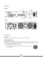
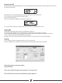
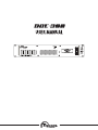
Caution
Before any operation please check the operation voltage switch 110\220V at the left side of the
transmitter, wrong setting of this switch may cause damage to the transmitter
Fast operation
It is strongly recommended to read the entire user manual before operation.
DCE300 - Professional 300W FM Transmitter V6
DCE300 is a state of the art FM transmitter designed to be the core of every radio station.
Achieving perfect audio quality was our main goal, which means that no matter if your FM
station is 250W or 10kW, no compromise should be when dealing with audio quality.
Our engineers, with more than 20 years experience in the RF and audio field were
directed to use the most modern and advanced technology in the market while keeping
final product price attractive and competitive and also important, plug and play operation.
Package Contents
1x User manual CD
1x DCE300 transmitter
1x RDS cable
The result is even more impressive than planned.
The Exciter module is on a compact board, with over 95% Surface mount technology (SMT) to improve performance, an excellent
1W exciter with a modern PLL and fully digital control with LCD display.
Audio input chain designed perfectly beginning with a shielded XLR balanced input connector to cancel any interference from
noisy RF environment.
Limiter will limit the modulation to the bandwidth occupation specified by the FCC and international standards.
RDS (Radio Data System) is today a standard module in every radio station, a complete RDS module has been integrated inside
the DCE300 including all main features of expensive professional stand alone RDS external modules.
The improved Stereo encoder, use a DSP technology with over sampling, to ensure excellent performance staring from low
distortion, accurate channel separation and stable pilot tone,
An external MPX generator, external RDS/SCA generator or audio processor can be connected to the MPX IN BNC connector to
bypass all internal audio chain.
At factory default, all internal modules - the audio chain, limiter, stereo encoder, RDS and 1W PLL exciter module including the
final stage Low Pass Filter (LPF) already connected and tuned for maximum performance without any need for user tuning.
From the 1W exciter module (TX190) the signal goes to the amplifier section that run by BLF278 made by Philips NXP that make
300W output power (typical 250W) and controlled by the digital controller inside the transmitter.
The amplifier has also Temperature and SWR protections and has also Low pass filter build in.
An PWM operation is given by the mean well power supply that is protected also.
With emphasis of 24/7 operation without any malfunction, we are sure, that our DCE300 will bring new audio quality for
many thousands audiences all over the world.
SPECIFICATION
GENERAL
Power Supply: MeanWell SE-600-48V - 700W 110/220V
Size: Standard 19” enclosure 2U size
Dimensions: 430X470mm
EXCITER MODULE
RF Output Power: 1 Watt typical (1.5W MAX)
Frequency range: 87.5Mhz-108Mhz no-tune
Output Impedance: 50 Ohms
Output connector: SMA
Frequency steps: 50Khz
MPX or SCA input: BNC unbalanced 10Kohm impedance
Harmonic output: <55dBc
Spurious output: <80dBc
Out of lock RF power-down: <-55dB
S.N.R: >75dB
RDS GENERATOR MODULE
Operation mode: Stand alone
Programming with a standard PC LPT port
Data storage: EEPROM during power off
On/Off selectable from main LCD display
Signal Bandwidth: 2.4Khz
RDS carrier: 57Khz (over-sampled x 3.2)
Conforms to CENELEC EN50067
4 modes of Dynamic/Scrolling PS
Supports: PI,PS,PTY,TP,AF,TA,DI,M/S,RT,UDG
STEREO ENCODER MODULE
Sub-carrier generation: over-sampled x 8
Pilot generation: 19Khz ± 2Hz ( over-sampled x16)
Stereo separation: >55dB (20Hz-15Khz)
MPX output level: unbalanced 75ohm (BNC connector)
LIMITER MODULE
Audio input connector: Balanced XLR
Input impedance: 10Kohm
Pre-emphasis: None, 50uS or 75uS
Input CMRR: >65dB
Frequency response: 20Hz–20Khz
AMP300 MODULE
RF Output power : 250W typical (350WMax)
Output Impedance : 50 Ohms
Frequency Range : 87.0MHz- 108MHz
Harmonic rejection : -60dB
Input voltage : 48V/10A DC
LPF section : Included
FEATURES
Compact size - SMT design
Single power supply with onboard voltage regulators
Microprocessor controlled with LCD display
Excellent audio response
Selectable Pre-emphasis: None, 50uS or 75uS
Balanced shielded XLR input connectors
Audio Limiter
Stereo Encoder using a modern DSP technology
RDS (Radio Data System)
Excellent VCO with low distortion
Phase Lock Loop (PLL) system with 50Khz steps for worldwide operation
Full Broadband design – no tune for 87.5MHz -108MHz
1W RF output power with LPF for clean spectral
Theory of operation
AUDIO LIMITER
Audio signals are supplied from 2 XLR balanced connectors – Left and right which being converted from balanced to unbalanced by low noise operational
amplifiers.
The audio channels are than pre-emphasised (50uS or 75uS) and passed threw a variable gain amplifier which changes the gain according to the levels of the
audio inputs, when high level of audio input is inserted into the amplifier, his gain reduces and output level will remain the same amplitude - this produce
the limiter function.
STEREO ENCODER
The stereo encoder is based on a microcontroller and a high performance analog switch, the 19Khz pilot is generated with a D/A technology by the
microcontroller (DSP), this technology produce a much improved spectral clearness and reduce the harmonic compared to other pilot generation methods, By
that a "softer" MPX filter can be used which improves overall spectral and channel separation.
Audio channels from limiter section are being switched by an improved analog switch device, intended for high speed switching and better specifications,
which also improve overall performance of the MPX signal.
RF SECTION
The base of the RF section is a VCO (voltage controlled oscillator), a VCO produce a frequency corresponding to an input voltage, mixing the audio with the
control voltage will generate FM signal (Frequency Modulation).
To Stabilize the VCO frequency, a Phase Lock Loop circuit (PLL) is being used.
The PLL compares a digital divided sample from the VCO with a very stable and accurate reference frequency, based on a crystal oscillator, and generates
a tuning voltage for the VCO.
The VCO output is being buffered and amplified to 1W by a RF power transistor and than passed threw a Low Pass Filter (LPF) for harmonic rejection.
RDS GENERATOR
The RDS (Radio Data System) uses a dedicated microprocessor to generate a direct digital RDS signal using a synthesize technology to create a 57Khz signal
at 361Khz sampling rate (over-sampled x 3.2).
It can be programmed using a PC, but stores all information in internal EEPROM memory which stores information after power down for a stand alone operation.
The RDS microprocessor includes all major features for the RDS standard :
PI (Program Identification),PS (Program Service),PTY (Program Type),TP (Traffice program),AF (Alternative Frequency),TA (Traffic Announcement),DI
(Decoder Identification),M/S (Music/Speech),RT (Radio Text),UDG (User Defined Group)
The RDS signal is being mixed into the MPX signal with a variable resistor to change to deviation level of the RDS.
MAIN CONTROLLER
The main controller of the DCE300 controls the LCD display, buttons, stereo/mono mode, PLL programming , final RF power switch, RDS on/off and also
monitoring the lock status to power down if out of lock occur due to failure.
The last frequency used is stored on an EEPROM to save frequency setting as well as RDS and STEREO/MONO mode when power is off.
On power up, the controller will make test for the PLL operation, will program last frequency from internal EEPROM memory into PLL and wait till frequency
lock.
After frequency lock, it will enable the RF power stage and monitor it while waiting for buttons to be pressed.
MAIN AMPLIFIER
The final stage amplifier is an Tugicom AMP300 based on 2XBLF278 by Philips NXP with protected output power of above 250W, great stability, PWM
controlled and Temperature and SWR protected .
The amplifier gets 1W drive from the exciter and output up to 300W in the 88-108Mhz band with clean spectrum image and contain LPF section.
Theory of operation
Pre-emphasis (None/50uS/75uS)
Factory set to 75uS
In an FM system the higher audio frequencies are more sensitive to noises than the lower frequencies. Because of that all FM receivers attenuate the high
audio frequencies in order to cut noise level.
Therefore a pre-emphasis for the higher frequencies is used to compensate the receiver attenuation.
There are 2 pre-emphasis modes used worldwide: 75uS - U.S.A, Japan and 50uS – Europe, Africa, Australia, New-Zealand,
When connecting AUDIO from external audio processor, some processors may add pre-emphasis, adding pre-emphasis also by the TX190 will make the
audio sound with too much treble because pre-emphasis must by applied one time only, in this case, the pre-emphasis on the TX190 need to be set to "none"
to allow external pre-emphasis.
If pre-emphasis is set to "none" instead of 50uS or 75uS, a major lack of treble will be noticed.
In order to set pre-emphasis 2 jumpers must be used, one for Left channel and one for Right channel.
Both channels must be set to same pre-emphasis.
When using external MPX signal, there is no effect for those pre-emphasis settings.
MPX bypass On/Off
Factory set - On
The TX190 has 2 options for MPX input.
When using the XLR connector to input the audio signal, the MPX bypass must be set to "On", when an external MPX generator is being used, MPX bypass
must be set to"Off" and MPX generator should be connected to the MPX IN BNC connector.
Please take note that setting the bypass to "Off" position without any external MPX generator will result that no audio will be transmitted even when audio
is connected to the XLR inputs.
STEREO Mode - Stereo on/Stereo off (Mono)
Factory set to Stereo on
This jumper activates or deactivates the stereo pilot tone.
For stereo broadcast, the TX190 broadcast a special pilot tone at 19Khz with 8Khz deviation.
When jumper is open (no jumper placed), stereo pilot tone is present and receivers will open the Stereo decoder circuit.
When jumper is closed (jumper is placed), pilot tone will be deactivated, without pilot tone receivers will not activate the stereo decoder circuit and a mono
reception will be used.
Limiter Mode – Limiter On/Limiter Off
Factory set to Limiter on
Limiter function is very important in order to prevent modulation exceeding 75Khz which is specified by The FCC.
Exceeding the 75Khz modulation will result in poor audio quality and interference to other radio stations.
In case that an external limiter is being used, the internal limiter should be set to off.
The limiter input and output has also clipper for protection against high levels.
Please remember to set both left and right channels to on or off, each channel has its own jumper.
Limiter Mode – Loud Mode/Pure Mode
Factory set to Loud Mode.
When limiter is on, there are 2 modes of operation for the limiting when the difference is the speed of limiter function.
Loud mode (fast mode) will keep volume at maximum levels but will slightly make audio sound less natural.
Pure mode (slow mode) will keep audio natural but will be a slight loss of volume.
To decide which Limiter mode is preferred, switch between loud and pure modes and listen to find your preferred choice.
Both Left and Right channels has their own jumper, please remember to set both channel to same mode of operation.
Limiter clippers – Clippers On/Clippers Off
Factory set to Clippers On.
Clippers are the last limiting function in order to protect against over modulation (more than 75Khz).
If external audio processor is being used, you may switch the limiter clipper off but should be very careful not to exceed the 75Khz deviation by adjusting
the correct levels in the external audio processor.
Both Left and Right channels has their own jumper, please remember to set both channel to same mode of operation.
Getting started
Front panel
A\B\C Buttons
RF Monitor
DCE300
FM digital exciter
V5.0 /"2008
www.tugicom.com
Output power limit
LCD Display
Rear Panel
RF Output
PUSH
RDS DATA
MPX IN\OUT
ON\OFF Button
GND
FUSE
PUSH
Audio IN
AC 220\110V Input
Connecting the unit
Power source
The DCE-300 require only standart AC 3 pole cable , connect it to your AC 220/110V at your studio.
Connecting the audio inputs
The TX190 has 2 XLR balanced inputs.
For balance audio source: Pin 1 is the Ground, pin 2 is the signal in normal polarity and pin 3 is the signal in inverted polarity.
For unbalance audio source: both pin 1 pin 3 connected to the audio source ground, pin 2 connects to the audio source live signal.
Note: 1. balanced signal has more immunity to external noises.
2. Most CD's and computer audio outputs are unbalanced.
1
2
not connecting both pins 1 and 3 together in case of unbalanced audio source will result in poor
audio or no audio at all.
3
5
Connecting the Antenna
Connect a 50 Ohm antenna or dummy load.
The antenna is one of the major elements which effect the range of the broadcast.
CAUTION
1.a wire is not an antenna, connecting unmatched antenna or not connecting antenna at all will damage the final RF amplifier stage.
2. Do not pass the antenna near the DCE-300 or the audio cables; this could add undesired noises to the broadcast.
Warning
Some of the commissioned items, particularly transmitters, require an operating license.
It is an offence in some other countries of the world to radiate electro magnetic waves at certain frequencies without a license.
It is the Customer's responsibility to check relevant laws, regulations and directives regarding licensing and putting into service any
goods commissioned by Tugicom. The Customer agrees to defend,
indemnify and hold harmless Tugicom, it's employees and agents, from and against any claims, actions or demands, including without
limitation legal and accounting fees, alleging or resulting from the improper or unlawful use of goods commissioned by Tugicom.
Finally - Make it work
Recheck that 50 Ohm dummy load or antenna is connected properly, power is connected and switched off, and audio source
is connected to the XLR inputs.
Turn on the power.
After switched on, the DCE-300 will perform a power up sequence, in first time operation the display should show:
This is the first time we are going to setup the DCE300 - The first screen setup is the freq’ adjust - with A and B buttons you can set the freq’
and when you are done press C button - Next.
The second setup screen is power output adjust - again with A and B set the power you want the then C when you are ready.
Next there are stereo\mono switching and RDS on\off screens - with A and B button choose on\off and C to confirm.
when you pass the RDS manu the screen will show on the screen the word - update .
From the setup the DCE will go ON-Air with all the setup sets that we insert on the setup - you can return to setup from the main manu by
pressing the C button.
Getting it on the AIR
When you exit the setup menu the DCE300 will start to lock on the desired frequency with the desired power output, usually it take about 10 seconds.
The display should look like this:
On the display you can see the transmitting frequency , the current output power and the reflected power.
You can return to the setup menu any time by pressing the C button.
A button is for Back light operation
There is also an info menu, press B button to enter it, this display will show up:
You can see here all info about the power supplies and the unit’s temperature also the modulation meter in action.
Using the RDS
Install the RDS software supplies with on the CD on a standard PC with a parallel port.
Connect the RDS cable to the DATA connector on the DCE300 rear panel and the other side to the parallel port on the PC.
In order to check that the DCE300 connected properly to the PC, press “Receive” button on the RDS software, the “DEFAULT PS” should show
“ * RDS * “ which means that the software and DCE300 are communicating.
Many efforts has been done to make the software user friendly, if any question occur please refer to help section in the RDS software.
IMPORTANT :
The “Send” button only sends new configuration but does not store it for next operation.
In order for configuration to be saved in the non-volatile memory, the “Store” button MUST be pressed after “Send “ button.
Thank you for purchasing one of our products.
Tugicom RF Design.
Come visit our website for updates and new products: www.tugicom.com
Please check the rules in your country before operating radio equipment.