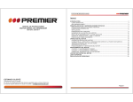
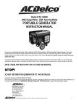
1
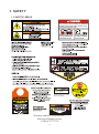
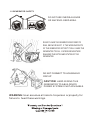
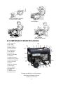
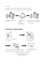
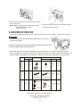
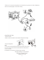
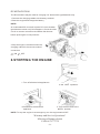
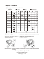
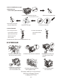
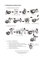
Owner s Manual
GG7500N Series Gasoline Generators
Do Not Return To Store
One year or 60 hours Limited Warranty (see page23)
For customer service or warranty information call toll free
866 797 2738
Read carefully before attempting to assemble, install, operate or maintain the product described. Protect
yourself and others by observing all safety information. Failure to comply with the user , s manual
could result in personal injury and/or property damage! retain the user ,s manual for future
reference.call toll free number 866 797 2738 for parts and service.
DISCLAIMER: All pictures may not be identical to product inside box.
Distributed by
Fullerton, CA 92833
SAFETY ALERT SYMBOL: Indicates danger, warning, or caution. Attention is
required in order to avoidserious personal injury.
The signal word (DANGER, WARNING, or CAUTION) is used with the alert
symbol to alert you to special instruction about a particular operation
that may be hazardous if pe rformed incorrectly or carelessly. Observe them
carefully.
DANGER: Failure to obey a safety warning will result in
serious personal injuries or deaths.
WARNING: Failure to obey a safety warning can result in
serious personal injuries or deaths.
CAUTION: Failure to obey a safety warning may result in
minor or moderate injuries
CAUTION: Never remove the caution symbols. Failure to follow all
instructions may cause damage to your engine or other property.
If you do not understand any portion of this manual, about engine,
please call customer service.
CONTENTS
1.SAFETY
2.COMPONENT IDENTIFICATION
3.PRE-OPERATION CHECK LIST
4.STARTING THE ENGINE
5.GENERATOR USE
6.STOPPING THE ENGINE
7.MAINTENANCE
8.STORAGE
9.TROUBLESHOOTING
10.WIRING DIAGRAM
11.SPECIFICATIONS
12.WHEELKIT
13.PARTS LIST AND DIAGRAM
13.1 CRANKCASE ASSY.
13.2 CYLINDER HEAD ASSY.
13.3 CAMSHAFT ASSY.
13.4 CRANKSHAFT ASSY.
13.5 CRANKSHAFT ASSY. & PISTON
13.6 CENTRIFUGAL TIMING IMPLEMENT ASSY.
13.7 INFLAME ASSY.
13.8 STARTER ASSY.
13.9 ENGINE SPROCKET COVER
13.10 CARBURETOR ASSY.
13.11 AIR CLEANER ASSY.
13.12 CHOKE ROD ASSY.
13.13 GENERATOR
13.14 GAS TANK ASSY.
13.15 PANEL ASSY.
13.16 MUFFLER ASSY.
13.17 MOTOR SHIELD ASSY
13.18 FRAME ASSY.
13.19 ACCESSORIES.
13.20 EXHALATION SYS
14 PARTS REPLACEMENT LIMITED WARRANTY
15 PRODUCT REGISTRATION CARD
Warranty and Service Questions ?
Missing or Damaged parts
Call 866 797 2738
1
3
4
5
6
9
9
11
11
12
13
14
14
14
15
16
16
17
17
17
18
18
18
19
19
20
20
21
21
21
22
22
22
23
24
1. SAFETY
1.1 SAFETY LABELS
Using a generator indoors CAN KILL YOU IN MINUTES.
Generator exhaust contains carbon monoxide. This is
a poison you cannot see or smell.
NEVER use inside a home
or garage, EVEN IF doors
and windows are open.
ADD OIL
BEFORE
USE
Connect ground to earth
before operating
Connect ground to earth
before operating
Warranty and Service Questions ?
Missing or Damaged parts
Call 866 797 2738
-1-
Only use OUTSIDE and
far away from windows,
doors, and vents.
1.2 GENERATOR SAFETY
DO NOT USE INSIDE A HOUSE
OR ANY ENCLOSED AREA.
DO NOT LEAVE THE GENERATOR EXPOSED TO
RAIN, SNOW OR SLEET. IF THE WORKING PARTS
OF THE GENERATOR GET WET IT WILL CAUSE THE
GENERATOR TO FAIL. EXCESSIVE MOISTURE
DAMAGES THE ROTOR AND STATOR OF THE
GENERATOR.
DO NOT CONNECT TO HOUSEHOLD
CIRCUIT.
CAUTION: HARD WIRING THIS
`
GENERATOR TO A BUILDING S
POWER SYSTEM IS NOT ADVISABLE.
WARNING: User assumes all risks to his person or property for
failure to heed these warnings.
-2-
KEEP FLAMMABLE MATERIAL
AT LEAST 1m(3FT).AWAY
NO SMOKING.
STOP ENGINE.
BEFORE REFUELING
DO NOT SPILL.
2.COMPONENT IDENTIFICATION
1
2
3
4
5
6
7
FUEL TANK CAP
FUEL TANK
FUEL GAUGE
ENGINE SWITCH
DC PROTECTOR
DC TERMINALS
HOUR METER
8 VOLTMETER
9 CIRCUIT BREAKER
10 HANDRAIL
11 DOUBLE SOCKET
12 FORE POLE SOCKET
13 GROUND TERMINAL
14 OIL FILLER CAP
15 WHEEL
16 RECOIL STARTER
17 FUEL VALVE
18 AIR CLEANER
19 CHOKE ROD
20 FRAME
21 FRAME COVER
22 CHECK VALVE
22
21
1
2
3
4
5
6
7
8
9
20
19
18
10
17
16
15
14
Warranty and Service Questions ?
Missing or Damaged parts
Call 866 797 2738
-3-
13
12
11
3.PRE-OPERATION CHECK
.
WARNING:
Warranty and Service Questions ?
Missing or Damaged parts
Call 866 797 2738
-4-
3. AIR CLEANER
1.Unsnap the air cleaner cover springs,and remove the air cleaner cover
2.Check the air cleaner element to be sure it is clean and in good condition.
3.If it is dirty,remove and clean
the element.
(1)Wash in solvent
4.Reinstall the air cleaner element
(2)Squeeze
and secure the cover by setting
(3)Soak oil
the cover spring.
(4)Squeeze dry
4.STARTING THE ENGINE
1.Disconnect any load from the
2.Turn the fuel valve to
AC receptacle.
the ON position.
3.Pull the choke rod out to the CLOSED
position.
Check the air cleaner element tobe sure it is clean.
4.Turn the engine switch to the
ON position.
Warranty and Service Questions ?
Missing or Damaged parts
Call 866 797 2738
-5-
5.Pull the starter grip lightly until resistance is felt
then pull briskly.
Warning:Do not allow the starter grip to snap
back against the engine.
Return it gently.
6.Push the choke rod to the OPEN
position
as the engine warms up.
5.GENERATOR USE
To keep the generator always in top mechanical and electrical condition, observe the following:
WARNING
1.To prevent electrical shock from faulty appliances, the generator
should be grounded.
Connect a copper wire to the generator and the other end of wire
to a metal stake driven into the ground.
2.Combined load of the connected apparatus must not exceed the rated capacity of the generator
Electric apparatus, particularly motor-driven equipment, will draw a higher current when starting. The
following table is provided for your reference when connecting such apparatus to your generator.
WATTAGE
Motor driven equipment Fluorescent lamp
Incandescent lamp
Heating appliance
TYPE
STARTING
EXAMPLE
RATED TYPICAL APPARATUS
Incandescent lamp
X1
APPARATUS
X1
TV
Fluorescent lamp
Refrigerator
X3~5
100VA
(W)
100VA
(W)
80VA
(W)
60VA
(W)
100W
40W
X1.5
X2
STARTING RATED
Incandescent lamp
Fluorescent lamp
Refrigerator
450~750VA 300VA
(W)
(W)
X2
150W
Electric fan
Warranty and Service Questions ?
Missing or Damaged parts
Call 866 797 2738
-6-
3.When two or more pieces of apparatus are connected to your generator, turn them on beginning
with the one drawing higher current when starting.
AC APPLICATION
1.Start the engine
2.Make sure that the needle on the voltmeter indicates the voltage.
3.Plug in the appliance
ON
Note:
OFF
a: Over current will automatically turn off the AC breaker. When that is
turned off, the generator shall be restarted with load reduced a few
minutes thereafter.
B: Generally 5-10% variance of voltage output is allowed.
Warranty and Service Questions ?
Missing or Damaged parts
Call 866 797 2738
-7-
DC APPLICATION
The DC terminals may be used for charging 12V automotive-type batteries only
1.Connect the charging cables to the battery terminal.
2.Start the engine and charge the battery
NOTE:
An overloaded DC circuit will trip the DC circuit breaker
(push button comes out) If this happens. Check the short
circuit or counter connection and wait a few minutes
before pushing the circuit protector.
3.Stop the engine, then disconnect the
charging cables in the reverse order of
connection.
1
ON
2
OFF
6.STOPPING THE ENGINE
1.Turn off all electrical appliances.
2.Turn the engine switch
to the OFF position.
3.Disconnect the electrical
appliance.
4.Turn the fuel valve to the
OFF position.
NOTE: To stop the engine in an emergency, turn the engine switch OFF.
Warranty and Service Questions ?
Missing or Damaged parts
Call 866 797 2738
-8-
7.MAINTENANCE
(1):These items shoule be serviced by a dealer.
(2):Every 3 years
Check
Change
Check-Readjust
Clean
SEE page
First month
or
Every 3 months
or
Every 6 months
or
Every year
or
Engine
oil
P.3
P.9
Air cleaner
P.3
P.3
Fuel strainer
P.9
Battery
fluid level
P.9
Spark plug
( 1)
Valve Clearance
( 1)
Combustion
Chamber
Fuel line
1.OIL CHANGE
4.Install the drain plug and tighten it securely.
1.Remove the oil filler cap.
5.Refill with the motor oil(see 3 page)and check the oil level
2.Remove the drain plug and drain the oil.
ENGINE OIL CAPACITY:37.2oz(1.1 Liter)
3.Dispose of oil property.
6.Install the oil filler cap.
Recommended oil: 4-stroke motor oil service classification SJ,SL,SG or SAE10W-30 for general
temperature.
Warranty and Service Questions ?
Missing or Damaged parts
Call 866 797 2738
-9-
2.AIR CLEANER(See 4 page)
3.SPARK PLUG
TYPE:F7RTC(NGK-BPR6ES)
1.Remove the spark plug cap.
2.Remove the spark plug.
0.7~0.8mm(0.028~0.031in)
5.Reinstall the spark
plug and plug cap.
4.Measure the gap.
3.Clean the deposit.
4.FUEL STRAINER
1.Turn the fuel valve
2.Clean the sediment
to the OFF position
cup and fuel filter
and remove the se
screen.
diment cup and
filter screen.
3.Install the fuel filter screen and sediment cup.
8.STORAGE
1.Close the fuel valve, drain
the fuel from the fuel tank.
4.Tighten the oil drain plug
and fill the engine with
new oil to the filler neck.
2.Drain the fuel from the carburetor.
5.Pull the starter grip carefully
until resistance is felt.
Warranty and Service Questions ?
Missing or Damaged parts
Call 866 797 2738
- 10 -
3.Remove the oil filler cap
and drain plug to drain
the oil.
6. Store the generator
in a clean area.
9.TROUBLE SHOOTING
9.1 ENGINE DOES NOT START:
1.Turn on the engine switch.
2.Check fuel.
5.Check spark.
3.Check oil.
4.Remove spark plug.
9.2 NO ELECTRICITY:
ON
OFF
Check AC circuit breaker
9.3 LIGHTS FLICKERING
1. Check for loose connections
2. Check for loose brushes and clean commutator
3. Check for proper load.. A certain amount of flashing
is normal with a light to moderate load
4. Check and adjust idle speed control screw 1/4-1/2
turn counter clockwise.
5. Check and clean carburetor.
Warranty and Service Questions ?
Missing or Damaged parts
Call 866 797 2738
- 11 -
Idle speed
control screw
In case long term storage generator has no output when started, please disconnect all
appliances and prod the ARM to increase the throttle until the volt-meter indicates voltage
10.WIRING DIAGRAM
CIRCUIT
BREAKER
BL
BL
R
R
BL
W
AC OUT
BL
BL
W
VOLT METER W
Br
W
R
R
R
CIRCUIT
BREAKER
G
G
G
W
G
W
DIODE
DIODE
BL
BL
MAIN
WINDING
Br
W/R
Br
Gr
Br
W/R
Br
DC PROTECTER
(+)
BL
(-)
B
G/W
G
BL
Gr
Gr
BL
EXCITER
WINDING
AVR
BL
G/W
G/W
R
Br
Y
FIELD WINDING
RED
BLUE
R
B
W WHITE B R BROWN
G GREEN Y YELLOW
B L BLACK
B
G/W
G
BL
C
Y
B
R
DC OUT
DC
WINDING
ENGINE
SWITCH
OIL
ALERT
UNIT
G/W
Y
OIL LEVEL
SWITCH
SPARK
PLUG
IGNITION COIL
SOLENOID
VALVE
NOTE:This engine is not designed to be plugged into a household circuit. User
assumes all risks associated with connecting this generator to a home circuit.
Warranty and Service Questions ?
Missing or Damaged parts
Call 866 797 2738
- 12 -
GROUND
TERMINAL
11.SPECIFICATIONS
Package(LxWxH)(in)
27.16
21.26
22.05(690
540
560mm)
Net weight(Ibs)
156.5(71kg)
Model
GG7500N
Type
Single phase, AVR
Rated voltage(V)
120/240
Rated frequency(Hz)
60
Rated current(A)
50/25
Rated power(kW)
6.0
Surge power(kW)
7.5
Power factor(cos( ))
1.0
DC rated voltage(V)
12
DC rated current(A)
10
Safety device
N.F.B
Engine
JF182FPH-2
Type
Air-cppled single cylinder.
4-stroke engine
Displacement (CC)
338
Start mode
Recoil start
Operation time(hr)
9
lgnition system
TCI
Fuel type
Unleaded gasoline
Oil type
SAE 10W-30/SAE 10W-40
Note: specifications subject to change without prior notice.
Warranty and Service Questions ?
Missing or Damaged parts
Call 866 797 2738
- 13 -
12.WHEEL KIT
1.Install the two wheels on the
generator using two bolts .
2.Install the crutches on the under frame.
2.Install the handrails on the right frame.
HANDRAILS
WHEELS
BOLTS
CRUTCHES
13.PARTS LIST AND DIAGRAM
13.1 CRANKCASE ASSY
NO.
PARTS NO.
DESCRIPTION
QTY
1
QJ182QDP.01-11
Buse, locating
2
2
157.5-10
SPACER, drain
2
3
157.5-9
BOLT, drain
2
4
QJ150FMG.5-8
DOWEL PIN
2
5
GB5787-86
BOLT M6 12
4
6
QJ182QDP.01.04
Sensor Assy, Fuel level
1
7
157-1-6-13
NUT
1
8
QJ182QDP.01-01
COVER, CRANKCASE
1
9
QJ168QDJ.01-05
SEAL WASHER
2
10
QJ168QDJ.01-03
PLUG, ADD OIL
1
11
GB5787-86
BOLT M8 40
7
12
QJ182QDP.01.01
13
QJ168QDJ.01-04
14
QJ182QDP.01-03
OIL SEAL 52 34
8
OIL LEVEL STICK
2
1
SPACER, CRANKCASE
1
35
11
2
72
17
1
15
GB/T276-94
Bearing6202 15
16
GB/T276-94
Bearing6207 35
17
QJ182QDP.01-10
Pin
1
18
QJ182QDP.01-05
ELECTRONIC SWITCH
1
19
QJ182QDP.01-09
CLIP, Cord
1
20
QJ182QDP.01-08
SEAL GASKET, rubber
1
21
GB5787-86
BOLT M6 25
2
22
QJ182QDP.01.03
OIL SEAL
1
23
QJ182QDP.01.02
CRANKCASE ASSY
1
Warranty and Service Questions ?
Missing or Damaged parts
Call 866 797 2738
- 14 -
13.2 CYLINDER HEAD ASSY
NO.
PARTS NO.
DESCRIPTION
QTY
1
QJ182QDP.02.01
Cylinder Head Assy
1
2
QJ182QDP.02-01
Bolt, Cylinder Head
4
3
QJ182QDP.02.02
Cover Assy
1
4
QJ182QDP.02-03
Spacer, Seal
1
5
QJ182QDP.02-04
Clamp
1
6
QJ182QDP.02-02
Bolt
1
7
QJ182QDP.02.03
Spacer Assy
1
8
QJ182QDP.02-05
Bolt, Intake Pipe
2
9
QJ182QDP.02-06
Cowling
1
10
GB5787-88
Bolt M6 12
1
11
QJ182QDP.02-07
Spacer, Intake Pipe
1
12
QJ182QDP.02.04
Spark Plug(NGK-BPR6ES)
1
13
QJ182QDP.02.02-02
Washer
1
14
QJ182QDP.02.01-05
Canal, Intake Valve
1
15
QJ182QDP.02.01-03
Canal, Exhaust Valve
1
16
QJ182QDP.02.01-04
Ring, Exhaust Valve
1
17
QJ182QDP.02.01-04
Ring, Intake Valve
1
18
GB/T6177-2000
Nut M6
2
Warranty and Service Questions ?
Missing or Damaged parts
Call 866 797 2738
- 15 -
13.3 CAMSHAFT ASSY
NO.
PARTS NO.
DESCRIPTION
QTY
1
QJ182QDP.03-12
Exhaust valve
1
2
QJ182QDP.03-11
Lower retainer
1
3
QJ182QDP.03-05
Valve spring
2
4
QJ182QDP.03-08
Exhaust valve spring retainer
1
5
QJ182QDP.03-09
Valve rotator
1
6
QJ182QDP.03-04
Pivot bolt
2
7
QJ182QDP.03-06
Valve rocker arm
2
8
QJ182QDP.03-07
Rocker arm pivot
2
9
QJ182QDP.03-11
Pivot adjusting nut
2
10
QJ182QDP.03-10
Intake valve spring retainer
1
11
QJ182QDP.03.02
Push rod
2
12
QJ182QDP.03-03
Push rod guide plate
1
13
QJ182QDP.03-13
Intake valve
1
14
QJ182QDP.03-01
Valve lifter
2
15
QJ182QDP.03.01-06
Spring
1
16
QJ182QDP.03.01-02
Pin
1
17
QJ182QDP.03.01.01-01
Fly clump
1
18
QJ182QDP.03.01.01-02
Fly clump
1
19
QJ182QDP.03.01.01-03
Pin
2
20
QJ182QDP.03.01-03
Pin
1
21
QJ182QDP.03.01-01
Camshaft
1
22
QJ182QDP.03.01-04
Decompress clump
1
23
QJ182QDP.03.01-05
24
QJ182QDP.03.01
Pin
1
Camshaft comp.
1
13.4 CRANKSHAFT ASSY
NO.
PARTS NO.
DESCRIPTION
QTY
1
QJ182QDP.04-01
BALANCE SHAFT
1
2
QJ182QDP.04-02
NUT
1
3
QJ182QDP.04-03
WOODRUFF KEY
1
4
QJ182QDP.04-04
CRANKSHAFT(1-type)
1
5
QJ182QDP.04-05
CRANKSHAFT GEAR
1
6
QJ182QDP.04-06
CRANKSHAFT GEAR
1
7
GB/T276-94
Bearing6207
1
Warranty and Service Questions ?
Missing or Damaged parts
Call 866 797 2738
- 16 -
13.5 CRANKSHAFT ASSY & PISTON
NO.
PARTS NO.
DESCRIPTION
QTY
1
QJ182QDP.05-01
PISTON
1
2
QJ182QDP.05-02
RING 1ST
1
3
QJ182QDP.05-03
RING 2ND
1
4
QJ182QDP.05.01
RING SET OIL
1
5
QJ182QDP.05-04
PIN, PISTON
1
6
QJ182QDP.05-05
CIRCLIP
2
7
QJ182QDP.05.02
CONNECTING ROD ASSY
1
8
QJ182QDP.05-02-01
CONNECTING ROD
1
9
QJ182QDP.05-02-02
CONNECTIONG ROD CAP
1
10
QJ182QDP.05-02-03
CONNECTING ROD BOLT
2
13.6 CENTRIFUGAL TIMING IMPLEMENT ASSY
NO.
PARTS NO.
DESCRIPTION
QTY
1
QJ182QDP.06-09
Pull Pole,
steel wire
1
2
QJ182QDP.06-10
Pull spring,ittle
1
3
QJ182QDP.06-01
Pull Ploe, Timing
implement
1
4
QJ182QDP.06-08
Pull spring, big
1
Nut M6
1
5
GB6177-2000
6
QJ182QDP.06-05
Washer
1
7
QJ182QDP.06-04
Fork
1
8
QJ182QDP.06-01-03
Governor weight
3
9
QJ182QDP.06-01-02
Governor weight pin
3
10
QJ166QDK.06-07
11
QJ182QDP.06.01-01
Centrifugal
Timing Implement
1
12
QJ166QDK.01-02
Clip
1
13
QJ182QDP.06-07
14
QJ182QDP.06-06
Handspike Cover
1
15
QJ182QDP.06-02
Clip
1
16
QJ182QDP.06-03
Bolt, Square Toes
1
Washer
Washer
1
1
13.7 INFLAME ASSY
NO.
PART NO.
DESCRIPTION
QTY
1
QJ182QDP.07.02
ROTOR ASSY
1
2
QJ182QDP.07.01
high voltage wrap
1
Warranty and Service Questions ?
Missing or Damaged parts
Call 866 797 2738
- 17 -
13.8 STARTER ASSY
DESCRIPTION
QTY
QJ182QDP.08.01-10
Handle
1
2
QJ182QDP.08.01-11
Pull Rope
1
3
QJ182QDP.08.01-09
Clockwork Spring
1
4
QJ182QDP.08.01-03
Rotary Table
1
5
QJ182QDP.08.01-05
Spring, Return
2
6
QJ182QDP.08.01-07
Screw
1
7
GB5789-86
Bolt M6x12
5
8
QJ182QDP.08-01
9
QJ182QDP.08-02
NO.
PARTS NO.
1
Starter Canister
Fan Wheel
1
1
10
QJ182QDP.08.01-01 Cowling Assy, cylinder
1
11
QJ182QDP.08.01-08
Guide Pan
1
12
QJ182QDP.08.01-04
Clump
2
13
QJ182QDP.08.01-06
Press Reed
1
14
QJ182QDP.08.01-02
Washer
1
15
QJ182QDP.08.01.01
Starter Cover Assy
1
16
GB5789-86
Bolt
3
17
QJ168FJH-3.08.01
Switch
1
18
QJ182QDP.08.01
Starter Assy
1
13.9 ENGINE SPROCKET COVER
NO.
PARTS NO.
DESCRIPTION
QTY
1
QJ182QDP.09
Speed djustment
base assembly
1
2
QJ168QDJ.05.01-02
Spring
1
3
GB818-2000
ScrewM5x35
1
13.10 CARBURETOR ASSY
NO.
PARTS NO.
DESCRIPTION
QTY
1
QJ182QDP.10.01
Carburator Assy
1
2
QJ182QDP.10-01
Carburetor packing
1
3
QJ153FM-0000041
Clip
1
4
QJ182QDP.10-02
Hose 4.5x 8.5x210
1
5
QJ182QDP.10-03
Hose 9x 12x150
1
Warranty and Service Questions ?
Missing or Damaged parts
Call 866 797 2738
- 18 -
13.11 CARBURETOR ASSY
NO.
PARTS NO.
DESCRIPTION
QTY
1
QJ182QDP.11
Air Cleaner Assy
1
2
QJ182QDP.11-6
Clip, Fixup
2
3
QJ182QDP.11-7
Clip, Fixup
2
4
QJ182QDP./11-8
Air Cleaner Cover
1
5
GB6177-2000
NUT M5
6
6
QJ182QDP.11-9
Core, Filtrate
1
7
QJ182QDP.11-3
Hole Board
1
8
QJ182QDP.11-4
Seal Gasket,
1
9
QJ182QDP.11-5
Below Shell, Air Cleaner
1
10
QJ182QDP.11-2
Air Cleaner
1
11
GB6177-2000
NUT M6
1
13.12 CARBURETOR ASSY
NO.
PARTS NO.
DESCRIPTION
QTY
1
QJ182QDP.02.02-03
Breath Tube
1
2
QJ182QDP.02.02-04
Rubber galosh
1
3
QJ182QDP.10.02
Choke vavle variable
pump comp.
1
4
QJ182QDP.10.02-03
Clip
1
5
QJ182QDP.10.02.01-01
Clip
4
6
QJ182QDP.10.02.01-02
7
QJ182QDP.10.02.01.01
Valve
1
8
QJ182QDP.02-08
Bakelite Washer
1
9
QJ182QDP.10.02-04
Rubber galosh
1
10
QJ182QDP.10.02.01
11
QJ182QDP.10.02-01 Choke vavle Pull pole
12
QJ182QDP.10.02-02
Rubber galosh
1
13
QJ182QDP.10.02.02
Breath body Assy
1
14
QJ182QDP.11-1
Air cleaner Packing
2
15
QJ182FPH-2.07-01
Pull pole
1
Hose
4x
8x135
Valve Assy
2
1
1
Warranty and Service Questions ?
Missing or Damaged parts
Call 866 797 2738
- 19 -
13.13 GENERATOR
NO.
CODE
DESCRIPTION
QTY
1
GB/T5787-86
Bolt M5*12
7
2
QJ6500.03-04
Right Cover
1
3
QJ6000.03.04
AVR
1
4
GB/T5789-86
Bolt M5*20
3
5
QJ6500.03-03
Connector
1
6
GB/T5789-86
Bolt M5*12
1
7
QJ6500.03.03
Rectifier
1
8
GB/T5789-86
Bolt M10*250*1.25
1
9
QJ6000.03.01
Brush Equipment
1
10
QJ6000.03-02
Motor Shell
1
11
QJ6500.03.01
Rotor Assy
1
12
QJ6500.03-06
Motor cover
1
13
QJ6000.03.03.01
BEARING, needle
1
14
QJ6000.03.03-06
Carbon Brush Ring
1
15
QJ6000.03.03
Stator
1
16
QJ6000.03.03-01
Impeller
1
17
GB/T95-85
Washer
3
18
GB/T93-87
Spring Washer
3
19
GB/T818-85
Bolt M5*12
3
1
2
8
3
4
5
9
6
7
10
11
12
13
14
15
16
17
18
19
13.14 GAS TANK ASSEMBLY
NO.
CODE
DESCRIPTION
QTY
1
QJ6800.01.01
Fuel Tank Comp
1
2
QJ950.13-02
Filtering Net
1
3
QJ6000.01.04
Fuel Tank Cap
1
4
GB/T819-85
Screw M5*10
2
5
QJ6000.01.03
Sender Unit
1
6
GB/T5789-86
Bolt M6*20
4
7
GB/T96.2-2002
Washer
4
8
QJ2600.01-02
Fuel Tank Rubber Hose
4
9
QJ2600.01-01
Fuel Tank Rubber
4
10
QJ6500.01.02
Fuel Valve
1
5
3
2
1
10
Warranty and Service Questions ?
Missing or Damaged parts
Call 866 797 2738
- 20 -
4
6
7
8
9
13.15 PANEL ASSY
NO.
CODE
DESCRIPTION
QTY.
1
KE6600D.02.01A
Panel
1
2
KE6600D.02.02A
Cable
1
3
QJ6500D.01.04
Rectifier Assy. 4A
1
4
GB/T818-85
Screw M3*12
1
5
GB/T923-88
Nut M6
1
6
GB/T6170-86
Nut M6
2
7
GB/T5789-86
Bolt M6*16
1
8
QJ6500.02.05
DC Terminal
2
9
GB/T818-85
Screw M3*12
2
10
QJ6500.02.04
DC Protector 10A
1
11
QJ6500D.01.04
Hour Meter
1
12
GB/T6170-2000
Nut M3
2
13
KE6600D.02-01
Bottom Shell
1
14
GB/T818-2000
Screw M4*12
8
15
GB/T95-2002
Washer
2
16
QJ3500.02.03A
Circuit Protector 30A
2
17
GB/T6177.1-2000
Nut M4
7
18
QJ3200.01.02
Double Socket
2
19
QJ6500D.01.03
4-Pole Socket
1
20
GB/T5789-86
Bolt M6*8
4
21
QJ2600.02.05A
Voltmeter
1
22
QJ6500.02.02
Engine Switch
1
DESCRIPTION
QTY.
13
12
14
10
1 2
8
7 9
4 5 6
3
11
15
16
17
18
19
22
21
20
1
13.16 MUFFLER ASSY
NO.
CODE
1
QJ6500D.03.01C
CARB Muffler
1
2
QJ6800.05-01
Muffler Cover
1
3
GB/T6177.1-2000
Nut M6
2
4
GB/T818-2000
Screw M6*25
2
5
QJ3500.05.03
Gulp Valve
1
2
13.17 MOTOR SHIELD ASSY
NO.
CODE
DESCRIPTION
QTY.
1
QJ6500.03-05
Motor shield
1
Warranty and Service Questions ?
Missing or Damaged parts
Call 866 797 2738
- 21 -
3
4
5
13.18 FRAME ASSY
8
NO.
CODE
DESCRIPTION
QTY.
Frame Jointing Assy
1
1
KE6600D.06.01A
2
QJ6000.08.02
Shockproof Big Mounting Feet
2
3
QJ6000.08.03
Shockproof Small Mounting Feet
2
4
GB/T6177.1-2000
Nut M8
4
5
GB/T6177.1-2000
Nut M10*1.25
4
6
GB/T5789-86
Bolt M6*10
8
7
KE6600D.06-02
Frame Cover
1
8
KE6600D.06-01
Frame Cover
1
7
6
5
1
13.19 Accessories
NO.
CODE
DESCRIPTION
QTY.
1
QJ6500D.04-06
Wheel Axis Bolt
2
2
QJ6500D.04.02
Wheel 4.10/3.5
2
3
GB/T6177.1-2000
Nut M6
2
4
GB/T5789-86
Bolt M6*40
2
5
QJ6500D.04-01A
Handrail
2
6
QJ6500.04-02
Handrail Jacket
2
7
GB/T6177-2000
Nut M8
4
8
GB/T5780-2000
Bolt M8*16
4
9
QJ6500D.04-03A
Crutch
2
10
QJ6800.06-01
Crutch Jacket
2
11
KE6600D.08-02A
Owners Manual
1
12
QJ6000.10.01
Saddlebag
1
6
19.20 EXHALATION SYS
NO
PART NO
DESCRIPTION
7
QTY
1
QJ6500D.07.01 Carbon Canister
1
2
QJ2900.08-01
Work Carriver
4
3
QJ2900.08-02
Rubber Pipe 1
1
4
QJ2900.08.02
Check Valve
1
5
QJ6500D.07-01 Rubber Pipe 2
1
6
QJ6500D.07-02 Rubber Pipe 3
1
7
QJ2900.08-05
Work Carriver
4
3
2
1
2
2
5
Warranty and Service Questions ?
Missing or Damaged parts
Call 866 797 2738
- 22 -
4
3
14.
- 23 -
PRODUCT REGISTRATION CARD
For more efficient customer service, please fill out the information below and mail to International Merchandising Service,Inc
Purchase Date
Engine Serial No.
Model No.
Purchased from: [ ]Retail location [ ] Private Consumer
[ ]Other
Name:
Location Address:
Telephone w/ area code:
Purchase Price:
Purchased:[ ] NEW or [ ]USED
Consumer Information:
Name
Telephone w/ area code:
Suite or Apt No.
Street Address:
City:
Province or Country
Are you a:
Zip Code
State
[ ]Business or [ ]Residence
Product usage Information:
How often will you use this product?[ ]Everyday
[ ]Periodically
[ ]Emergency use only
[ ]Light Commercial
[ ]Light Residential
[ ] Tradeshows
[ ]Other
What type of application will you use this product in?
[ ]Heavy Commercial
[ ]Heavy Residential
[ ]Other
[ ]Moderate Commercial
[ ]Moderate Residential
Mail this page to: International Mer Service, Inc,
1928 West Malvern Avenue
Fullerton,CA92833
- 24 -
[ ]Camping,backpacking