1
18
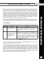
Mk 2
SECURITY
ENERGIZER
Installation and User Manual
9.2 9.0
o
p
Edition 2.1, 2013
JVA ELECTRIC FENCE SYSTEMS
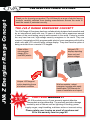
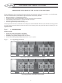
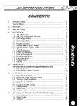
JVA Z Energizer Range Concept
JVA ELECTRIC FENCE SYSTEMS
Thank you for choosing our product. The JVA brand is a range of electric fencing
products carefully selected from leading manufacturers around the world to
meet the needs of perimeter security.
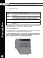
THE JVA Z RANGE ENERGIZER CONCEPT
The JVA Range of Energizers has been collaboratively designed and manufactured
by an international team with over 30 years of electric fence experience earned
in some of the most testing security environments in the world. It aims to provide
the very best low-cost, high-voltage security energizers in the world. They are
compact, integrated and fully programmable electric fence energizers with built-in
alarm units and LCD out and return voltage display. They also have the option of
being controlled from a remote LCD keypad.
State-of-theart energizer
design IP4 x
and ABS plastic
Unique LCD
display depicting
fence out and
return voltage
Unique LCD keypad
option depicting fence
and alarm condition
RANTY
WAR
Wall-mountable, robust
energizer housing with easily
detachable PCB chassis for
ease of installation and repair
TWO-YEAR WARRANTY
All JVA products carry a 2-year warranty against defective
components and workmanship. The warranty excludes damage
!"#!$$#%$#&'
supply surges, rough handling, malicious action or incorrect wiring.
Please retain your invoice as proof of purchase and
JVA ELECTRIC FENCE SYSTEMS
CONTENTS
INTRODUCTION ......................................................................................
3
2.
FEATURES ...............................................................................................
4
3.
SPECIFICATIONS ....................................................................................
5
4.
DESCRIPTION .........................................................................................
4.1 JVA Z18 Exterior ..............................................................................
4.2 JVA Z18 – High Voltage Terminals ..................................................
4.3 LCD Voltage Display ........................................................................
4.4 Status LED Lights ............................................................................
4.5 Keypad (Optional) ............................................................................
4.6 Keypad Lights ..................................................... .............................
4.7 Internal Beeper / Keypad Beeper ....................................................
4.8 Cabling ............................................................................................
4.9 Lightning Protection .........................................................................
4.10 Earth Loop Monitoring .....................................................................
4.11 Noise and Interference ....................................................................
4.12 Programmable Options ....................................................................
4.13 Low Power Mode .............................................................................
4.14 Control Inputs ..................................................................................
4.15 Group Simultaneous Pulse Feature ................................................
6
6
6
7
8
8
9
9
9
9
9
10
10
10
10
11
5.
INSTALLATION .........................................................................................
5.1 Installation Steps .............................................................................
5.2 Example Fence Wiring Diagrams ....................................................
12
6.
OPERATION .............................................................................................
6.1 Arm / Disarm Control .......................................................................
6.2 Arming the Fence Using the Keypad ...............................................
6.3 Turning to Low Power Mode ............................................................
6.4 When an Alarm Occurs ....................................................................
6.5 To Silence the Alarm ........................................................................
6.6 Changing the User PIN Number ......................................................
6.7 Standby Battery ...............................................................................
6.8 Status Light ......................................................................................
6.9 Keypad Control in Brief ....................................................................
6.10 Solar Powering the Unit ...................................................................
14
14
14
14
14
15
15
15
15
16
16
7.
TECHNICAL INFORMATION ....................................................................
7.1 Inputs and Outputs ..........................................................................
7.2 Power Options .................................................................................
7.3 Status Codes ...................................................................................
7.4 Jumpers ...........................................................................................
17
17
18
18
19
12
13
Contents
1.
1
JVA ELECTRIC FENCE SYSTEMS
Contents
8.
9.
10.
11.
12.
2
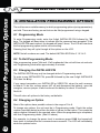
INSTALLATION PROGRAMMING OPTIONS ..........................................
8.1 Programming Mode .........................................................................
8.2 To Exit Programming Mode .............................................................
8.3 Changing the Installer PIN ...............................................................
8.4 Changing an Option .........................................................................
8.5 Programming Options in Brief .........................................................
8.6 Programming options in Detail ........................................................
8.6.1 Power Level (01x#) ..............................................................
8.6.2 Low Power Level (02x#) ......................................................
8.6.3 Fence Alarm Voltage (03x#) ................................................
8.6.4 Low Power Alarm Level (05x#) ............................................
8.6.5 Missed Pulse Count (06x#) .................................................
8.6.6 Battery Alarm Voltage (07x#) ...............................................
8.6.7 Siren On Time (08x#) ..........................................................
8.6.8 Siren Off Time (09x#) ..........................................................
8.6.9 Siren Cycles (10x#) .............................................................
8.6.10 Input Type (11x#) .................................................................
8.6.11 Input Function (12x#) ...........................................................
8.6.12 Gate Entry/Exit Delay (13x#) ...............................................
8.6.13 Chime Mode (14x#) .............................................................
8.6.14 Fence Mode (15x#) .............................................................
8.6.15 Binary Options (16x#) ..........................................................
8.6.16 Anti-Bridging Threshold (17x#) ............................................
8.6.17 Auto Re-arm Time (20x#) ....................................................
8.6.18 Relay Functions ...................................................................
8.6.19 Relay Function Details .........................................................
8.6.20 Group Mode (26x#) .............................................................
8.7 Diagram of Group Wiring .................................................................
ALPHA PLUS LCD KEYPAD FEATURES ................................................
9.1 Using the Alpha Plus LCD Keypad ..................................................
9.2 Changing the Keypad Messages and Address ................................
9.3 To Exit Keypad Programming ..........................................................
9.4 Other Keypad Functions ..................................................................
SECTOR SETUP TESTS AND ADJUSTMENT ........................................
10.1 Basic Fence Tests ...........................................................................
10.2 Fault Condition Tests .......................................................................
SOME STANDARD REQUIREMENTS FOR ELECTRIC
SECURITY FENCES ................................................................................
........................................................................................
11.2 Installation, Operation and Maintenance .........................................
11.3 Warning Signs .................................................................................
11.4 Gates ...............................................................................................
11.5 Earthing ...........................................................................................
11.6 Protection ........................................................................................
WARRANTY .............................................................................................
20
20
20
20
20
21
22
22
22
22
23
23
23
24
24
24
25
25
25
25
25
26
26
27
27
28
29
30
31
31
31
33
33
34
34
35
36
36
36
37
37
37
38
42
JVA ELECTRIC FENCE SYSTEMS
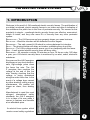
1. INTRODUCTION
Welcome to the world of JVA monitored electric security fences. The proliferation of
non-lethal, monitored, electric security fences in our towns and cities is indicative of
popularity is simple – monitored electric security fences are effective, economical,
simple to install, and they offer more D’s of security than any other perimeter
system:
Every second, the JVA Z energizer
discharges a very short-duration,
safe, high-voltage pulse down
the fence live wire. The JVA
Z energizer then monitors the
voltage at the end of this live
wire, thereby checking that the
voltage is being maintained
along the entire fence line. In the
event of a voltage drop caused
by either shorting, cutting or poor
maintenance, the monitor will
trigger an alarm, thus alerting
you.
Introduction
DEMARCATION – The JVA fence around your property shows you mean business.
DEFLECTION
DETERRENCE – The safe, powerful JVA shock is a strong deterrent to intruders.
DELAY – The physical barrier will delay an intruder, something they do not like.
DETECTION – The JVA’s voltage monitor warns you of any tampering with the fence.
DENY – A well-erected electric security fence will deny entry.
DEPENDABLE – 60 seconds a minute, 60 minutes an hour, 24 hours a day, 365 days
a year, your JVA electric security fence is monitored by an alert, sober, electronic
watchman.
Manufactured to meet the most
stringent international safety
standards, the JVA Z energizer
is in a class of its own when it
at an affordable price.
An electric fence system which
meets current safety regulations
3
JVA ELECTRIC FENCE SYSTEMS
2. FEATURES
2.1 Power
! 8 joules peak output energy
! Mains powered via external transformer (16–18Vac)
! Battery charger with space for internal 7A/H 12V rechargeable back up battery
2.2 Control / Monitoring:
! "$
%&'&$
! 2 12V driven outputs (also referred to as relays)
! 3 extra relays with change-over contacts
Features
! All relays may be assigned to any alarm function
! LCD voltage display
! LED status lights
! Internal beeper
! AC fail, Low Battery and Bad Battery detection
! Keypad programmable options
! Low power mode – ensures detection together with public safety during the day
! Adjustable energizer power output level
! Tamper/safety function
! Will operate with up to 3 keypads
2.3 Safety
! Designed to pass IEC60335.2.76 and EMC standards (reports available on
request)
! Enclosed fence terminals
! * +$; installation and repair
2.4 Reliability
! Microprocessor controlled
! Pluggable screw terminals
! <
*
*=+>?@;<
! =
X ?
lightning protection is still advised in high lightning prone areas
! @
[
4
JVA ELECTRIC FENCE SYSTEMS
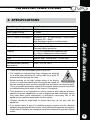
3. SPECIFICATIONS
Energizer Output Voltage
Peak Output Energy
Pulse Rate
12v DC Power Consumption
Outputs
Enclosure
Size
Weight – packed, no battery
Recommended operating
temperature
] [
] [
for a while after switching off, and to wait for at least 10
minutes before opening the case.
] ; % [
fence, it is recommended that the energizer be turned off WARNING
and an intentional short circuit be placed from the fence live wires to earth.
This is a sensible precaution against the energizer being turned on by others
or malfunctioning while work on the fence is in progress.
] *
sensory or mental capabilities, or lack of experience and knowledge, unless
they have been given supervision or instruction concerning use of the
appliance by a person responsible for their safety.
] $ [ appliance.
] =
^
between two separate electric fences, each powered by separate energizers,
"_
*
^
mode.
AC Power Input
Battery Charger Output
8.5kV peak no load
8 Joules
Locked at 0.9 Hz
Energizer On – 870mA average, 1220mA peak
Energizer Off – 28mA
Not including keypad or auxiliary power
16Vac 2A
Float voltage 14v, 700mA, short circuit protection
Reverse battery protection
3 × 12V 2.5A maximum combined load
3 × 30V 1A changeover relay contacts
IP4x ABS plastic
300mm high, 190mm wide, 115mm deep
2.5kg
From -15°C to +50°C
5
JVA ELECTRIC FENCE SYSTEMS
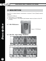
4. DESCRIPTION
The Z18 is a single channel, conventional or bi-polar 8 Joule (Output) security
energizer.
This manual relates to:
Description
! +$;[`{_
! |[`{_}~
[
$
on reset)
o
p
9.2
9.0
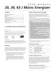
4.1 JVA Z18 Exterior
Figure 1: Z18 Exterior
!!"
Standard
Return
Earth
N/C
Feed
N/C
Earth
Figure 2a: High Voltage (Fence) Terminals in Conventional Mode
BiPolar
RET 1+
EARTH
RET 2-
+FENCE
EARTH
-FENCE
Figure 2b: High Voltage (Fence) Terminals in Bi-polar Mode
6
JVA ELECTRIC FENCE SYSTEMS
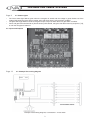
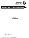
4.3 LCD Voltage Display
The display on the JVA Z18 shows the voltage at the Feed Out and Return
terminals.
Left side = Return, Right side = Feed.
;
*
[
[
and the right side is the negative return voltage.
The LCD also shows the programming option and current setting when in
programming mode. This allows the programming options settings to be checked
easily.
RETURN
p
FEED
POWER
ARMED
FENCE
GATE
Description
9.2 9.0
o
STATUS
Figure 3: LCD Display and Status LEDs
7
JVA ELECTRIC FENCE SYSTEMS
#$%&$!
Description
(See Figure 3.)
Power
–
On whenever the energizer has power.
Armed
–
' ^ ~X power mode.
Fence
–
^
[
X
[
|
@
X
Gate
–
Flashes Red when the Gate input is open, stays Red when there is
a gate alarm.
Status
–
Flashes an error code for energizer (service) errors. See the table
in Section 7.3
Fence and gate LEDs are latched on (like the strobe) until cleared, using the clear
alarm memory sequence (*1#), or until the energizer is rearmed.
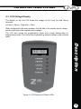
4.5 Keypad (Optional)
Up to 3 keypads can be used to remotely monitor and control the Z18. The keypad
is also used to set the programmable options. See section 8.5.
To provide feedback to the user the LCD keypad utilizes two LEDs and a LCD
display. A description of each LED’s function and the messages that may appear on
the LCD display can be found in the table below. (Section 4.6)
The fence Out and Return voltages are displayed when the Z18 is armed.
Figure 4: LCD Keypad
8
JVA ELECTRIC FENCE SYSTEMS
'*+$!
On
@$*
On ^~*
mode.
!"#: There is no panic function.
For information on how to control the Z18 via the keypad see section 6.
!"#: By pressing the House key
the display will toggle between any alarm
conditions, trouble conditions and voltage conditions.
Depending on the chime setting, the internal beeper and keypad beeper will sound
*
'
battery the keypad will always beep 4 times before the energizer automatically enters
low voltage mode to preserve the battery. On AC Fail it will not beep.
!"#: The internal beeper also beeps at power-up.
4.8 Cabling
High voltage cabling (fence lead out and returns) should be run using suitably rated
cable. Double insulated electric fence “underground” cable is suitable. High voltage
cables must $be run within the same conduit as low voltage cables. A minimum
distance of 30mm should be kept between high voltage and low voltage cables.
Description
4.7 Internal Beeper/Keypad Beeper
,$!!-
Although the Z18 contains internal lightning protection elements, external lightning
protection elements such as additional external lightning kits available from your
local dealer, are recommended as they would help to reduce lightning damage even
further.
0%$+6!
The Z18 has two fence earth terminals which when wired into an insulated series
looped fence system enable the energizer to monitor the earth circuit. If this is not
required the installer can loop the two earth terminals at the energizer and then
connect the earth spikes to one of the parallel earth terminals.
9
JVA ELECTRIC FENCE SYSTEMS
4.11 Noise and Interference
The Z18 contains a microprocessor. Extreme electrical noise can upset microprocessors. The most likely cause of such noise is the high voltage output from the
unit itself. In the event of erratic behaviour, check that the high voltage wiring is
%
to self-recover from interference, powering off (both AC and battery) should not be
necessary.
Description
4.12 Programmable Options
The Z18 has many programmable options. These are also known as setup
parameters. To alter these options a keypad must be used. The options are explained
in Programming Options in Brief on page 21. Each parameter has a factory set
default.
4.13 Low Power Mode
Z18 energizers can be switched into low power mode. Low Power mode may be used
in situations where the fence is not required to be a deterrent but is still required to
actively detect intrusion. In Low Power mode the fence live wires operate at a much
lower voltage, typically 500V peak. See Programming Options in Brief on page 21 for
details on using the keypad to set low voltage mode.
4.14 Control Inputs
The Z18 has 2 control inputs. These default to:
Input 1 – Arm/Disarm
Input 2 – Gate Switch or High/Low power control
The gate input may be wired to a gate switch to trigger an alarm when a gate is
opened.
%&'
The Gate Input may be wired to a gate switch to trigger an alarm when the gate is
opened for longer than the Gate Entry/Exit Delay time (Option 13). The timer will
reset to zero when the gate closes.
If the energizer is disarmed, the Gate Input may be set to Chime Mode. See
Programming Options in Brief on page 21.
!"#: If Gate Input feature is not used, the Gate Input must be looped.
If the unit is disarmed, the gate input may be set to Chime mode.
10
JVA ELECTRIC FENCE SYSTEMS
()
When the Gate=
+*
Gate Input
is able to change the energizer output (while armed) to either High Power or Low
Power modes. It is also used to determine what Power Mode to start in when the
energizer is armed.
4.15 Group Simultaneous Pulse Feature
In some installations it may be preferable to provide the ability to link multiple units
into a group. When linked, the individual Z14s, Z18s and Z28s become a group.
@ ^ =[ [
simultaneous high voltage output pulses and act as if they are one energizer with
multiple outputs. This is designed so that no possible combination of individual
outputs can be dangerous.
Description
11
JVA ELECTRIC FENCE SYSTEMS
5. INSTALLATION
*+,-.',
5.1 Installation Steps
1.
2.
Installation
3.
4.
5.
6.
7.
8.
9.
10.
11.
12.
13.
14.
15.
16.
17.
Design and build the fence. (Beyond the scope of this manual.) Ask your
distributor for help if required.
Decide where the JVA Z18 is to be mounted. If on an external wall it
?
sunlight or where it could get wet.
Mount the unit by hanging the housing on the two nail-in anchors provided.
If necessary, two extra mounting holes can be used at the bottom of the
housing.
=%*[
%?
Wire the low voltage cables to the PCB terminals (right side)*. (See page 17)
Wire the high voltage cable to the PCB terminals*. (See page 6) If earth
monitoring is not going to be used on the fence, connect a bridge wire
from earth out to earth return.
Fit the battery leads to the battery. The Status LED should blink twice to
show mains fail.
Mount the 220 – 16V transformer and connect the 16V side to the Z18
16V input terminals. (AC is not polarity sensitive.) Do not connect a live or
neutral to the earth terminal.
[
state of the inputs.
Replace the front cover.
Turn AC power on. The Status LED should stop blinking.
Enter the keypad initialisation code *68#.
@
^[
%
%*
Arm the unit. The LCD display will now show the fence voltage.
Check to ensure that a short anywhere on the fence triggers the alarm.
Ensure that the user understands how to change the user code (PIN) and is
in possession of this Installer/User Manual and the installer’s contact details.
*: *+!9!;9!00
+
&!;9!
&;!<""!"#=
If an electric fence is part of a multiple energizer system and the distance between
two separate electric fences, each powered by separate energizers, is less than 2,5
*
^
12
JVA ELECTRIC FENCE SYSTEMS
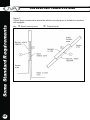
5.2 Example Fence Wiring Diagrams
Return
Feed
Earth
Feed
Earth
Return
Energizer Earth
Example Fence Wiring Diagram, Conventional – Live & Earth,
including earth monitoring
Positive
Negative
Installation
Conventional Fence
FenceEarth Out
Fence+
Return 2
Earth Return
Return 1
Negative Feed
Positive Feed
Negative Return
Positive Return
Bi-polar Fence
Energizer Earth
Example Fence Wiring Diagram, Bi-polar – All Live
13
JVA ELECTRIC FENCE SYSTEMS
6. OPERATION
6.1 Arm/Disarm Control
The unit can be controlled by the keyswitch, control input 1 (IN1) or via a keypad.
The keypad also allows instant audiovisual indication of the state of the energizer
and therefore the fence it is powering.
If there are two ways to control the energizer both connected at once, i.e. keypad
and control inputs, then the last change will determine the result. So if the unit is
armed via the keypad and then disarmed at the control input it will disarm.
'
!=>!*+
Operation
! Enter your >#< & number (four digits long) and push the # key.
! Make sure the red ARM light comes on.
! %
! The fence will power up and if all is well (no faults) the system will be ready to
deter and detect.
! If there is a fault on the fence and it cannot achieve full voltage, Fence LED will
! To disarm the system, enter your >#<& and press #. This will also clear any
fault lights and zone lights which may have been on.
'?"!$;-;6
To switch to Low Power mode, enter your >#<& and press *41#. In Low Power
mode the fence will still be powered and any breach will be detected, but the voltage
@
+
mode.
Enter your >#<& and press *42# to switch back to Full Power mode.
Alternatively, the unit can be switched to Low Power mode using the gate switch
input, if it has been programmed accordingly.
'@
H
=
*
|&$
on the energizer and then remain on. Relays assigned to alarms will turn on. If the
energizer is connected to a building alarm system for monitoring, an alarm signal
may be sent to the alarm company monitoring the alarm system.
An alarm will also sound if the gate input is opened and the entry/exit delay time
has elapsed.
14
JVA ELECTRIC FENCE SYSTEMS
After the Siren has cycled on and off according to the times and numbers set in
options, the siren will stop sounding. The on and off timing is able to be set in the
options. The Strobe will remain on. After a further delay (Auto Rearm Time) the siren
will again respond to the next alarm condition with a new set of on / off cycles.
If the alarm condition (Low Fence Voltage or Gate Input) is removed, the siren will
stop after the end of the Siren On Time).
If the siren is muted by (entering >#<&@) then the siren will enter the next Siren
Off Time. If the alarm condition is still present (voltage is low) the siren will sound
again after the preset “off” time. If the alarm condition is not present the energizer is
instantly rearmed, irrespective of the auto-rearm setting.
'Q"#
! Enter your >#<&and press @This will silence the alarm but not disarm the
X
?
remain visible until the Clear Alarm memory command is entered (*1#).
! Alternatively, disarming using the key switch will reset the alarm.
! When a Z series security energizer is a member of a group and goes into alarm, it
can be silenced by disarming and rearming that energizer using the Disarm/Arm
Zone commands. See 6.9 Keypad Control in Brief.
''T!!>#%U-XYY
!
!
!
!
!
Enter the old 4-digit >#<&and press BC@This enters User Programming mode.
Enter your new >#<&(must be 4 digits) and then #.
Press *# to exit User Programming mode.
Make sure your new >#<&works by using it to arm the energizer.
The default >#<&is 1 2 3 4.
Operation
! The keypad text display will show the respective zone alarm.
! The siren and strobe are ready to respond again if triggered.
! To disarm the system enter your >#<&and press @again. The Zone light will
6.7 Standby Battery
Should there be a loss of mains power, the Power Light on the keypad will go off.
Output power will be reduced to conserve battery power. If the loss of power is
prolonged, the battery may discharge power and become ineffective. The Power
Light
=
requires replacement, the Power Light
Status Light
times.
'#$!
If the energizer develops an internal fault, the Status Light <
section 7.3 (page 18).
15
JVA ELECTRIC FENCE SYSTEMS
6.9 Keypad Control in Brief
Operation
The default USER PIN is 1 2 3 4.
Key Sequence
Arm/Disarm
[User PIN][#]
Silence an Alarm (Single zone system only)
[User PIN][#]
Start programming the Z series energizer
[Installer PIN][*] [0] [#]
Start programming the Keypad
[Installer PIN][*] [0] [1] [#]
Exit Programming (any mode)
[*] [#]
Change a User PIN
[User PIN][*]0[#][New PIN]#
Change the Installer PIN – in programming mode only
[0] [0] [New Installer PIN][#]
[User PIN][*][1][0][#]
Arm Zone 1 (Master)
[User PIN][*][1][1][#]
Arm Zone 2 (On Z28 or slave in group)
[User PIN][*][1][2][#]
Disarm All Zones
[User PIN][*][2][0][#]
Disarm Zone 1 or Master
[User PIN][*][2][1][#]
Disarm Zone 2 (On Z28 or slave in group)
[User PIN][*][2][2][#]
Switch to low power mode (all zones)
[User PIN][*][4][1][#]
Switch to high power mode (all zones)
[User PIN][*][4][2][#]
Keypad Audible Feedback Toggle
[*] [5] [1] [#]
[*] [5] [3] [#]
!"
"
[*] [5] [4] [#]
$%&"
[*] [8] [#]
Display Keypad Model
[*] [9] [#]
'
&+,
-
.
[User PIN][*][6][8][#]
Reset and return to factory defaults
[Installer PIN][*] [6] [8] [#]
Power Boost
[*] [9] [9] [#]
Siren Test
[*] [6] [3] [#]
7
"
&,
[*] [6] [4] [#]
Clear alarm memory
[*] [1] [#]
'0#-;!>
If there is no mains power on the site, the Z18 can be powered as follows: A 56 Amp/
hour battery charged by a 120 watt solar panel. This is a guideline. A bigger panel
=
?
*
Jumper J3.
16
JVA ELECTRIC FENCE SYSTEMS
7. TECHNICAL INFORMATION
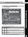
7.1 Inputs and Outputs
Please refer to the Low Voltage diagram above.
Label
IN1
Gate
Keypad
Type 2 Way Energizer Control Input (dry contact). Defaults to normally open.
Can be used for a remote switch or a radio receiver. The receiver
may be powered from the keypad +12V terminal. NOTE: This input
is wired in parallel with the SW2 keyswitch input.
2 Way !
&=&
>&&?&
=&@&
-
H&
gate input can be used for low power mode remote arming and
disarming.
3 Way Supplies power and data line for an external keypad. The +12 source
&
&
&
$&
,&J
>
L>
@
Technical Information
Low voltage connector layout – Note the 3 relay outputs
Low Voltage Terminals (continued on page 18)
17
Technical Information
JVA ELECTRIC FENCE SYSTEMS
Label
Type Siren
2 Way Switched 12 volt output. 30W max (including
(Relay 1)
&.
@.
.
,
$
$&&&
to an alarm panel. 2.5A Fused*
Strobe
2 Way Switched 12 volt output. 30W max (including
(Relay 2)
@.
.
,
$
$&&&&
an alarm panel. 2.5A Fused*
16Vac
2 Way JQX$,
&@Y
-Y\\
>
L>
@
Relay 3
3 Way Defaults to General alarm. But may be set to any of 13 alarm
$@Y&^=_`j&$
$&qJ{X&&
>&'
@
2.5A Fused*
Relay 4
3 Way Defaults to AC Fail alarm. But may be set to any of 13 alarm
$@Y&^=_`Q&$
$&qJ{X&&
>&'
@
2.5A Fused*
Relay 5
3 Way |
>&&^,7
@&.
&&>J\
$@Y&^=_`}&$
$&qJ{X&&
>&
Relay. 2.5A Fused*
7
^
J{X$.7
$
$-YJ\
>
L>
@
$&'
&.7
-
q&
@
* All of the relays (1 – 5) use the same 2.5A fuse.
!"#: To reset the fuse, remove power for a few seconds and then reapply power.
7.2 Power Options
The unit has 2 sources of power, 16VAC and 12VDC (battery).
!"#: Use only rechargeable batteries. Always ensure adequate ventilation is
available for the housing if it contains a battery. Lead acid batteries may emit explosive
@%
^
before applying AC. The energizer cannot operate without a battery.
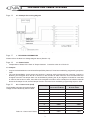
7.3 Status Codes
'#
'-D
&
$
1
Tamper detected
Fit the lid
2
16 VAC Mains fail
Restore mains power. Can be
3
Low battery, bad battery Charge or replace battery
4
PCB service fault
Default the unit (See 7.4 (J4) below)
Status Codes
18
JVA ELECTRIC FENCE SYSTEMS
If an error has momentarily caused the energizer to stop pulsing, this can be corrected
by disarming and rearming the unit. Should the error recur, return the unit for service.
7.4 Jumpers
The unit has two special purpose jumpers (links). These are listed in the table below.
*'
J3
D'
'
Inhibit Mains fail error.
is to operate the energizer on DC only (as in solar
power systems). Disables the Infrared Tamper
feature
OR Tamper disable
J4
Factory default jumper If the energizer needs to be defaulted to factory
Off to return program- settings, remove all power – AC and battery and
remove the J4 jumper. Reapply the battery power
mable options to
* @$ >
factory defaults upon
and
the unit will be reset to default settings. If the
power up
Status
*
nearest JVA service centre.
Jumpers
Jumper J3 also disables the new infrared Tamper/Safety feature, if it has been
enabled by programming sequence 168#.
The new Tamper/Safety circuit serves two functions. It protects service personnel
from receiving a shock by disarming the energizer when the lid is removed. It also
sounds an alarm when the lid is removed while the energizer is armed. The tamper
alarm can be inhibited by shorting the J3 pins together. It should be noted that in
order for this function to work, the inside of the energizer lid needs to have a small
[
[
=
*
have been enabled by the programming sequence 168#.
Technical Information
If an error occurs, the relay assigned to general alarm will go into alarm state. Minor
errors will self clear if the error condition is removed. If the mains power fails, it
will not disarm the energizer, nor will low battery. However, without mains power,
the battery will eventually be depleted and the energizer will attempt to maintain
operation by entering Low Power mode after 4 warning beeps. If the battery charge
continues to fall, the energizer will eventually stop. Once mains power has been
restored and the battery has recovered, the energizer will re-arm itself automatically
after 4 warning beeps. A tamper or a PCB fault will disarm the energizer. If an error
disarms the energizer, the fence alarms will be activated.
19
Installation Programming Options
JVA ELECTRIC FENCE SYSTEMS
8. INSTALLATION PROGRAMMING OPTIONS
The unit has a non-volatile memory in which programming options (setup parameters)
%
8.1 Programming Mode
To enter Programming mode, enter the 6-digit INSTALLER PIN followed by *0#
keys. The keypad will beep twice to indicate that the command was accepted. If the
INSTALLER PIN was incorrect, the keypad will beep 3 times. The LCD will now show
Pressing the # key will cycle through all the options on the LCD.
!"#: Not all numbers are used. The default INSTALLER PIN is 0 1 2 3 4 5.
"%\-!
!6
After programming, press B@ to exit. If left unattended, the unit will time out and auto
exit Programming mode after approximately 5 minutes.
?T!!XY#"$$%U PIN
The INSTALLER PIN may only be changed while in Programming mode.
To enter a new INSTALLER PIN, press 00 followed by the new 6-digit INSTALLER
PIN, then the # key.
If you cannot remember your INSTALLER or USER PIN, return the unit’s memory
to default. To do this, remove power (AC off and disconnect the battery), open the
energizer, remove jumper J4 and reconnect the battery for about 10 seconds.
>
This will return all options to the factory set defaults.
T!!H+
Most of the options have possible values in the range of 0 to 9.
To change any options, the unit must be in Programming mode. Check the option
number (see table below) and then the table of values for that option. Then press the
option number followed by the required value. When the programming is completed,
exit from Programming mode. (See 8.2 above.)
For example, to change the power level to maximum press 019#, the keypad will
beep twice to indicate that the command was successful. The LCD will immediately
show the updated value.
20
JVA ELECTRIC FENCE SYSTEMS
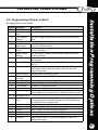
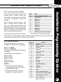
See page 22 for more detail.
!
D'
Sets the output power levels
Sets the output power levels used in Low Power mode
08
Power Level
Low Power
level
Fence Alarm
Voltage
Not used in Z18
Low Power
Alarm Level
Missed Pulse
Count
Battery Alarm
Voltage
Siren On Time
09
Siren Off Time
10
Siren Cycles
11
12
Input Inversion
Gate Input
Function
Gate Exit Delay
Chime Mode
Fence Mode
Binary Options
Anti-Bridging
01
02
03
04
05
06
07
13
14
15
16
17
Sets the voltage threshold below which the fence alarm will
occur
Sets the voltage threshold below which the fence alarm will
occur in Low Power mode
Sets the number of pulses which may be missed before the
alarm is activated
Sets the battery voltage threshold below which the general
alarm will activate
Sets the time that the siren (and keypad beeper) will stay on
after an alarm
The amount of time the siren will be off after the On time has
expired
The number of times the siren will sound for the On
time function above. After this many cycles the siren will
automatically mute
Normally open or normally closed
Gate Switch mode or Low Power Switch mode
Time from gate switch opening to alarm
Allows the keypad and internal beeper function to be altered
Bi-Polar or Conventional mode
Miscellaneous options
If the voltage rises OR falls quickly by more than this setting as
a percentage of the average fence voltage the alarm will occur
18 – 19 Not used in Z18
20
Auto-Rearm
Sets the time which must elapse after an alarm has timed out
Time
(completed the siren cycles) before the unit will automatically rearm, ready for the next alarm event.
21
Relay 1
Used to assign an alarm function to output L1 – Siren
22
Relay 2
Used to assign an alarm function to output L2 – Strobe
23
Relay 3
Used to assign an alarm function to RELAY 3
24
Relay 4
Used to assign an alarm function to RELAY 4
25
Relay 5
Used to assign an alarm function to RELAY 5
26
Group ID
Allows the energizer to be set as a Master or Slave in a
synchronised group.
Installation Programming Options
8.5 Programming Options in Brief
Programming Options
21
Installation Programming Options
JVA ELECTRIC FENCE SYSTEMS
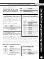
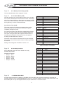
8.6 Programming Options in Detail
GHE
$ICEJ@K
The power level option allows the shocking
power of the fence to be adjusted. For example:
To change the power level to maximum, enter
the following:
Note: The bold panel in each table
indicates the default value.
+'
IJK
+
+
$ :
;,
;,
0
5.0kV
2.5kV
1
5.5kV
2.8kV
2
6.0kV
3.0kV
3
6.5kV
3.3kV
4
7.0kV
3.5kV
5
7.5kV
3.8kV
This setting affects the average power drain
and therefore backup battery time.
6
8.0kV
4.0kV
7
8.5kV
4.3kV
Kilovolt settings refer to a 1000 Ohm load,
actual fence voltages will depend on the type
and length of fence.
8
FCQ+
OQ+
9
9.5kV
4.5kV
CEF@ or CECF@.
The keypad will beep twice to indicate that the
new setting has been accepted.
The normal fence voltage depends on the amount
of fence wire, the losses and the power level.
Power Level (01x#)
GH
$ICJ@K
GHMD+ICMJ@K
Same as above, but for Low Power
mode.
This option sets the voltage threshold
below which the fence alarm will occur. The
default Fence Alarm Voltage is 4 kV.
+'IJK
L(
0
0.5%
1
1.0%
2
+'
IJK
+
$
;,
+
:;,
1.5%
0
1.5kV
1.5kV
3
2.0%
1
2.0kV
1.8kV
4
2.5%
2
2.5kV
2.1kV
5
3.0%
3
3.0kV
2.4kV
6
MOL
4
3.5kV
2.7kV
7
4.0%
5
CQ+
MCQ+
8
4.5%
6
4.5kV
3.3kV
9
5.0%
7
5.0kV
3.6kV
8
5.5kV
3.9kV
9
6.0kV
4.2kV
Low Power Level (02x#)
Fence Alarm Voltage (03x#)
22
JVA ELECTRIC FENCE SYSTEMS
This option sets the voltage threshold
below which the fence alarm will occur.
The default Fence Alarm Voltage is 500
Volts.
GHO;,''ICHJ@K
This option enables the pulse count to
be varied from the default (3). This is
the number of bad or missing pulses
that are counted before the alarm
occurs.
!"#: The lower this option is set, the
more likely you are to get false alarms.
+'IJK
;,
'
0
1
1
1
2
2
3
3
4
4
5
5
6
6
7
7
8
8
9
9
Missed Pulse Count (06x#)
+'IJK
+
0
300 Volts
1
OCC+
2
700 Volts
3
900 Volts
4
1100 Volts
Low Power Alarm Level (05x#)
GHH:+ICSJ@K
This option sets the battery voltage
threshold below which the alarm will
activate. The default Battery Alarm
Voltage is 10.0 Volts and the unit will
drop to low power at 9.0 Volts (after
beeping 4 times).
If the unit enters Low Power mode due
*
return to high voltage, without warning,
when the mains voltage comes back on
and the battery voltage rises.
U,
'-
<,'
0
9.0 V
8.0 V
1
9.5 V
8.5 V
2
ECC+
FC+
3
10.5 V
9.5 V
4
11.0 V
10.0 V
5
11.5 V
10.5 V
6
12.0 V
11.0 V
7
12.5 V
11.5 V
8
13.0 V
12.0 V
9
13.5 V
12.5 V
Battery Alarm Voltage (07x#)
Installation Programming Options
GH
$ICOJ@K
23
Installation Programming Options
JVA ELECTRIC FENCE SYSTEMS
GHSOn "ICGJ@K
+'
"
This option sets the duration of time that
the siren will remain on after a fence
alarm occurs. After this time the siren
will turn off for the Off time indicated in
Table 8.6.9. The siren will sound again
if the alarm is still present after this
Off time has passed. The default is 3
minutes.
0
10 Seconds
1
30 Seconds
2
1 Minute
3
2 Minutes
4
M;'
5
4 Minutes
6
5 Minutes
This may be the subject of local
regulations to stop an alarm causing
undue disturbance to neighbours, etc.
7
6 Minutes
20 Minutes
8
7 Minutes
45 Minutes
9
8 Minutes
130 Minutes
!"#: The siren On time will be cut
short if the battery falls below the low
battery level.
+'
0
1
2
3
4
5
6
7
8
9
"
10 Seconds
1 Minute
2 Minute
5 Minutes
EC;'
20 Minutes
30 Minutes
40 Minutes
50 Minutes
60 Minutes
Siren Off time (09x#)
!"#: This is the maximum number
of cycles for 1 continuous alarm,
intermittent alarm events could
cause more than this number of
siren soundings.
SFOD
Siren On time (08x#)
GHGOff ICFJ@K
This option sets the amount of time the siren
will be off for after the on time above has
expired. If an alarm is still present after this Off
time, the siren will sound again.
GHFIECJ@K
This option sets the maximum number of
times the siren will sound for the On time if
the alarm continues. This may be limited by
local regulations to stop an alarm causing
undue disturbance to neighbours, etc.
+'
0
1
2
3
4
5
6
7
8
9
0
1
2
3
4
5
6
7
8
9
Siren Cycles (10x#)
24
JVA ELECTRIC FENCE SYSTEMS
The Z18 inputs can be inverted.
Unless the input is used for a Gate
switch, in which case it is always N.C.
+'
D'
0
!I!K
1
Normally Closed (N.C.)
Input Inversion (11x#)
GHEE&'D'IEJ@K
GHE%#)#JIEMJ@K
This option is used to set the function for
the Input Gate. If set to 0, the gate alarm
will trigger if the gate is opened for longer
than the Gate Entry/Exit Delay. If set to 1,
the energizer will go into Low Power mode
if this Input is closed.
This option sets the time between the
gate switch opening and the siren
sounding.
+'
"
0
0 Seconds (immediate)
1
30 Seconds
2
E;'
D'
3
2 Minutes
0
%
4
3 Minutes
1
Low Power
5
4 Minutes
6
5 Minutes
7
6 Minutes
8
7 Minutes
By default, the input is set to Gate.
+'
Input Function (12x#)
GHEM;,IEJ@K
9
8 Minutes
This option allows the energizer’s internal,
and keypad, beeper to be used as a
Gate Entry/Exit Delay (13x#)
door chime for the gate switch. When set
to None, the keypad beeper is used to
indicate correct keypad operation only. When set to Door Chime, the beepers will
sound when the gate switch opens, even if the energizer is disarmed.
If set to Siren, the beepers mimic the siren function. Gate Beeps plus Siren will give
2 beeps on Gate Open and 4 beeps on Gate Close, plus a continuous beep for an
alarm. The beeps are from the keypad only, not from the internal beeper.
!"#: Gate must be selected in option 12.
D'
GHED;,IEOJ@K
0
None
1
Door Chime
This option sets Bi-Polar or
Conventional modes.
2
3
Fence Alarm
4
Gate Beeps plus Siren
+'
Chime mode (14x#)
+'
D'
0
Bi-polar
1
$
Installation programming options
GHEC&'"IEEJ@K
Fence Mode (15x#)
25
Installation Programming Options
JVA ELECTRIC FENCE SYSTEMS
26
GHEO:!IEHJ@K
+'
"
0
+1
Cross couple alarm
For option+ 1 set 16 to 01, for + 1 and
+2 set 16 to 03.
+2
Max Power
+4
2.5 Joules Limit
+1: Enable cross coupled alarm, not
used on Z series Energizers.
+8
IR Tamper enabled
+16
Stop slave on comms fail
+32
Do not send Alarm memory
Each option in this table can be turned
on by adding the corresponding value.
+2: Maximum power at all times. Note
turning this option on may remove IEC
standards compliance.
Binary options (16x#)
+4: Limits outputs to 2.5 Joules per Zone on a Z28. Also limits a Z14 to 2.5J per
zone in group mode.
+8: Enables the IR tamper detection under the lid. J3 changes function to inhibit
tamper.
+16: Stop slaves on E-16 if the communications from the group master is lost.
+32: Stops the energizer sending Alarm Memory to a PC, relay PCB or keypad. Set
this to restore “unlatched” mode on a PAE201 relay PCB.
GHEH:,",IESJ@K
Anti-bridging has been designed to detect a section of fence being bypassed, and
removed, by an intruder bridging the adjacent fence sections together.
Setting this option to a value greater than 0 (default is 0 = off) will enable Anti*[
While Armed, a Fence Alarm will trigger if the Fence Voltage rises OR falls quickly
by more than the threshold. A slow change to the voltage will not trigger a Fence
Alarm until the Voltage is less than the Fence Alarm Voltage (03x#).
The Anti-bridging Threshold is a percentage value of the current Fence Voltage.
For example, setting option 17 to 10 (1710#) will set a 10% Anti-bridging Threshold.
At this level a fence (return) voltage normally reading 7.5kV will trigger a Fence
Alarm if the voltage quickly rises to over 8.3kV or falls to less than 6.7kV.
!"#: In order for this alarm to operate, Power Level (Option 1) must be set higher
than the normal fence running voltage, otherwise if the load is released (fence
bridged) voltage control will limit the voltage rise and the anti-bridging alarm will not
activate. For the above example, Option 1 must be set to 7 or greater to allow the
unloaded fence to rise to 8.3kV or higher, thus triggering the alarm.
JVA ELECTRIC FENCE SYSTEMS
This option sets the time which must
elapse before another alarm will
out (gone completely through its
cycles).
+'
If an event occurs (such as a low
fence voltage) which triggers the
siren, any other events which would
otherwise trigger the siren (such as a
gate alarm) will be ignored while the
siren is sounding and until after the
Auto Re-arm time has passed.
A setting of 9 will disable Auto Re-arm.
"
0
C,I&,K
1
30 Seconds
2
1 Minute
3
2 Minutes
4
3 Minutes
5
4 Minutes
6
5 Minutes
7
6 Minutes
8
7 Minutes
9
Disabled – Do not auto rearm
Auto Re-arm Time Values (20x#)
If this time is set to less than the Siren Off Time, the energizer may re-arm in the Off
time and the number of Siren Cycles will be reduced.
GHEG<D'
All relays can be set to any of the
available functions (user assignable).
Relay 1 is (EJ@)
Relay 2 is (J@) etc.
The modes are explained in the table
alongside.
The defaults for the Z18 Mk2:
+'IJK
;,
0
DE
1
Fence 1 or Off
2
Armed 1
3
Fence 2
4
Fence 2 or Off
5
Armed 2
6
Fence Bi-polar
7
General
8
Siren
Relay 1 Siren
Relay 2 Strobe
Relay 3 Fence
Relay 4 Armed
Relay 5 General.
9
Strobe
10
AC Fail
!"#:
11
Low/Bad Battery
1. The siren and strobe switched
12V outputs can be used to drive
external buffer relays.
12
Tamper
13
Strobe 2
14
Gate
2. Group relay functions are only
operable on the group master.
15
Siren caused by Gate
16
Armed in Low Power Mode
17
Group Armed – Note 2
18
Group General
Relay Functions
Installation Programming Options
GHESAuto Re-arm "ICJ@K
27
Installation Programming Options
JVA ELECTRIC FENCE SYSTEMS
28
GHEF<D'
Some additional modes have been added to the relay functions as per table.
D'
IK
Zone x
Zone x is on AND the fence voltage has fallen below the programmed
fence alarm voltage for more pulses than the missed count setting.
Not latched.
Zone x
Zone x is Disarmed OR the fence voltage has fallen below the
alarm or off programmed fence alarm voltage for more pulses than the missed
count setting. Not Latched.
Fence
Bipolar
Energiser is Armed (Pulsing) AND the Fence Return Voltages on
either Bi-polar return line has fallen below the Fence Alarm Voltage
for more pulses than the Missed Pulse Count. Not latched.
Armed x
Zone x is Armed.
General
AC fail OR Low Battery OR Internal Error OR Gate Alarm. Latched
for internal errors only.
Siren
Fence Alarm Or Gate Alarm. Will time out after the siren time out
time. This function is latched.
Strobe x
As per siren but does not time out, will remain on until unit is
disarmed. This function is latched. Also indicates gate alarm.
AC Fail
Alarm on AC Fail.
Battery
Alarm on low or bad battery.
Tamper
@
Group
wide x
Group relay functions are the collected status of the whole group of
Z energisers. Group Armed for example is set only if all energisers
in the group are armed.
Relay Functions
JVA ELECTRIC FENCE SYSTEMS
A group must have only one master. The other units in
the group are slaves. Group voltage display units require
each slave to have a different number. Since the keypad
bus is common among the group one keypad can be
used to program all units for all options except this one.
The procedure is:
Connect the keypad to each unit in turn, before linking
all units into a group. Set this option: one unit as master
the other as slaves.
!"#: In some markets group mode may not be
available.
+'IJK
0
1
2
3
4
5
6
7
8
9
;,
%'
Master
Slave 1
Slave 2
Slave 3
Slave 4
Slave 5
Slave 6
Slave 7
Slave 8
Group Mode (26x#)
For details on group wiring and operation see page 30 Figure 5.
1.
2.
3.
4.
Make sure the key switch is turned off and IN1 is not looped.
Connect the battery.
Connect the keypad.
On the keypad, enter [Installer’s code] [*] [0] [#], then [26]. (Default Installer Code:
0 1 2 3 4 5.)
5. Enter the required value (e.g. [1] for master) then [#].
6. Enter [*] [#] to exit programming.
7. Connect the group using the keypad bus as per Figure 7.
!"#: At this time groups are limited to a master and 14 slaves. Only one keypad
can be used in Group Mode. If more slaves are required, use can be made of LAN
network interface cards (PAE212).
Installation Programming Options
GHC%';,IHJ@K
29
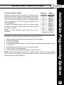
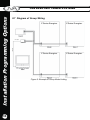
30
8.7 Diagram of Group Wiring
Z Series Energizer
Z Series Energizer
Z Series Energizer
Z Series Energizer
LAN cable
PAE212
LAN cable
Installation Programming Options
JVA ELECTRIC FENCE SYSTEMS
Figure 5: Example of Group Mode Linking
JVA ELECTRIC FENCE SYSTEMS
9. ALPHA PLUS LCD KEYPAD FEATURES
,>!+-$T&*+
The LCD keypad has two LED’s: Power and Arm. They act as follows:
Power: On
*
@`
'
^~X
Low Power mode.
All other indication is given via messages
on the screen.
Whenever the keypad displays:
ALARM ZONE
FAULTED ZONE
or SYSTEM TROUBLE
pressing the [#] key will reveal more
information, such as the name of the
zone or the actual system trouble,
e.g. AC Fail.
,T!!*+6!
The messages and each of the 15 zone labels can be changed.
! Dealer Message displays when the system is on standby.
! Zone Labels displays after the [#] key is pressed during alarm memory or faults.
! Service Message is displayed during AC failure, fuse failure,
communication failure, or low battery.
[1]
[2] Character up
[4]
[5] Next Message
w Cursor left
[3] not used
Emergency not used
Alpha Plus LCD Keypad Features
All JVA Z series energizers, including the Z18 Mk2, now have support for up to three
keypads. If more than one keypad is desired, one of the keypads must have an ID of
2. The other keypads can have an ID number from 1 to 8 but excluding ID 2. If only
one keypad is desired, any ID number from 1 to 8 can be used.
[6] x Cursor right Fire not used
[7]
[8] Character down [9]
Panic not used
[*]
[0] Last Message
Bypass not used
[#] Enter/Exit
Keys Used For Changing Messages
31
Alpha Plus LCD Keypad Features
JVA ELECTRIC FENCE SYSTEMS
32
! [
Keypad Programming Mode, enter the [&V,] [*] [0][1]
[#]. Information may be entered into the keypad in the form of letters (upper and
lower case), numbers (0–9), and 22 special symbols. All characters are displayed
in the order: upper and lower case letters, numbers, and special symbols. The
[Space] character precedes the letter A.
NOTE: The default Installer Code is 0 1 2 3 4 5.
! *
"%
the desired character. If you scroll past the desired character, the [8] key may be
used to scroll backwards. NOTE: The space character is before the A character
(When A is displayed, press [8] to get a space).
! *
%
[
the next character position. The [4] key moves the cursor to the left.
! [
*
%
and move to the next message position.
!
}%
[%
NOTE: If one moves to the next message using [5] instead of the [#] key, any
changes made will be lost.
The message order is:
! Service Message (Displayed under System Trouble)
! Dealer Message (Displayed under the standby message: Ready to Arm)
! (A, B, and C) not used
! ! Keypad Address
Up to three keypads may be used to remotely monitor and control the Z series
security energizers.
*%
Address, see section 9.2 Changing the Keypad Messages and Address. This is
best achieved by connecting one keypad, at a time, to the Master Energizer and
updating the Keypad Address. Once all keypads have a different address, all
can be connected to the system. A recommendation is that one keypad is kept at
Address 1. The energizer now needs to be introduced to all of these keypads. This
[
^
%~
@*
by pressing *68#. The power can also be removed to reset the energizer. After a
reset, the energizer will determine what keypads are connected, and only these
Addresses will be used in the future. This prevents un-authorised keypads being
added to the system once it is running.
JVA ELECTRIC FENCE SYSTEMS
NOTE: Keypad Addresses
LCD keypads should NOT be set to Address 8 as Address 8 uses a different
%
^ {[> %'
@"
The use of Perimeter Patrol further reduces the usable keypads to 1.
,?"%\*+-!
!
[*
,H*+=
! %
! %_
Alpha Plus LCD Keypad Features
If the security system is to use a PC based interface such as Perimeter Patrol,
Keypad Address 2 should not be used by a keypad. The PC software uses
this address to control the energizers. This also limits the number of keypads
on the system to 2.
33
Sector
SetupTests
Testsand
and Adjustment
Adjustment
Sector
Setup
JVA ELECTRIC FENCE SYSTEMS
34
10. SECTOR SETUP TESTS AND
ADJUSTMENT
With a single sector system there are three considerations for the electric fence
monitor voltage level:
1. The monitor should trigger the alarm if one of the live wires is shorted to ground.
2. The monitor should trigger the alarm if one of the live wires is cut.
Use common sense and turn the energizer off when making changes to the fence,
then turn the energizer back on to check the effects.
0^="
1. Energise the newly-completed fence.
"
|++
3. Check that there is voltage on all live wires (continuity) and that there are no
shorts from live to earth, or between live circuits (Bi-Polar).
4. Check the electric fence earth. (See electric fence manuals.) One method is to
make an intentional short from live wire to earthed metal (not +ve to -ve if using
Bi-Polar). The voltage at the earthed point should be less than a few hundred
[
X
[
%
should be less than a few hundred volts.
5. Record the start and end of fence live wire voltages.
!"#: Bi-Polar systems should have approximately equal voltages with respect
to earth.
6. Record the live wire currents going out from the energizer to the fence.
At this point there must be a reasonable voltage on all parts of the fence. To be an
effective barrier, the Power Probe (or voltmeter) readings between wires (live to
earth or +ve to -ve for Bi-Polar) must be greater than 5.0kV. If they are not, a larger
energizer may be required.
JVA ELECTRIC FENCE SYSTEMS
1. To simulate a break, disconnect a joint in the live wires at some convenient point
on the fence, making sure that the wires do not short to ground or between +ve
and -ve wires.
2. Check that the energizer fence alarm activates. If not, check the voltage (using an
electric fence voltmeter) at the inputs to the monitor. Set the fence alarm voltage
level higher than this voltage. If there is still considerable voltage, you may have
induced voltage in the live return wires. If so, reduce the induced voltage by
placing a 3000 Ohm, 10 Watt resistor between the live return and earth return
terminals (or from +ve to -ve in a Bi-Polar system) at the monitor.
3. Reconnect the live wires.
4. Place a short on the fence live wires.
5. Check that the monitor goes into alarm.
6. Remove the short.
Sector Setup Tests and Adjustment
0=T"
35
Some Standard Requirements
JVA ELECTRIC FENCE SYSTEMS
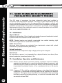
11. SOME STANDARD REQUIREMENTS
FOR ELECTRIC SECURITY FENCES
accordance with international standards. JVA does not take responsibility for the
erection standards of the fence. It is the responsibility of the erector to consult and
comply with the Standards and Codes of Practice for the installation and erection
of electric security fences. For the user’s convenience, we include some Standard
Requirements here but the installer also needs to consult standards such as SABS
1063, 0142, SABS IEC 60335-2-76.
&
-^
A barrier of not less than 1.5m in height and intended to prevent inadvertent contact
of persons with the conductors of the electric fence.
!"#: Physical barriers are typically constructed from vertical sheeting, rigid
vertical bars, rigid mesh or rods of chain wire mesh.
Public Access Area
Any area where persons are protected from inadvertent contact with pulsed
conductors by a physical barrier (see above).
Pulsed Conductors
Conductors that are subjected to high voltage pulses by the energizer.
Secure Area
An area where a person is not separated by a physical barrier (see above) from
pulsed conductors (see above) below 1.5m.
11.2 Installation, Operation and Maintenance
11.2.1 Electric security fences and their ancillary equipment shall be installed,
operated and maintained in a way that minimises danger to persons, and
reduces the risk of persons receiving an electric shock unless they attempt
to penetrate the physical barrier, or are unauthorised to be in the secure
area.
11.2.2 A space of 2.5m shall be maintained between uninsulated electric fence
conductors or uninsulated connecting leads that are supplied from different
energizers. This space can be less where the conductors or the connecting
leads are covered by insulating sleeving, or consist of insulated cables that
are rated to at least 10kV.
36
JVA ELECTRIC FENCE SYSTEMS
11.2.3 The requirement in 10.2.2 does not apply in cases where the separately
energised conductors are separated by a physical barrier that has no
openings greater than 50mm.
11.2.5 Mains supply wiring shall not be installed in the same conduit as signalling
leads associated with the electric security fence installation, but shall be
installed in accordance with the requirements given in SABS 0142.
* NB. (Fence HT leads must under no circumstances be routed in the same
conduit as any other wiring.)
11.3 Warning Signs
!"#: Regulation warning signs are available from all JVA
|
@
prominently placed warning signs that shall be legible
from the secure area and from the public area.
11.3.2 Each side of the electric security fence will have at least one warning sign.
11.3.3 A warning sign shall be placed:
a. at each gate
b. at each access point
c. at intervals not exceeding 10m
d. adjacent to each sign with regard to chemical hazards, for emergency
services information.
11.4 Gates
Gates in electric security fences shall be capable of being opened without the person
who is operating the gate receiving a shock.
Q %!
11.5.1 Where an electric security fence passes below bare power line conductors,
the highest metallic element shall be effectively earthed for a distance of not
less than 5m on either side of the crossing point.
Some Standard Requirements
11.2.4 A vertical separation of not less than 2m shall be maintained between pulsed
conductors fed from different energizers.
11.5.2 The distance between any electric fence earth electrode and other earth
systems shall be not less than 10m, except when the earth system is
associated with a graded earth mat. The earth electrode shall comply with
SASS 10611. Amendment 1, Deco 2000 1.
11.5.3 All exposed conductive parts of the physical barrier shall be effectively
earthed.
37
JVA ELECTRIC FENCE SYSTEMS
Some Standard Requirements
11.6 Protection
38
11.6.1 All ancillary equipment connected to the fence circuit shall be designed to
provide a degree of isolation between a fence circuit and the supply mains
[
^
11.6.2 Protection from weather shall be
provided for the ancillary equipment
the manufacturer as being suitable
for use outdoors, and is of a type
with a minimum degree of protection
IPX4 (protected against splashing
water).
$
;'
<1 000
3m
>1 000 and <33 000
4m
>33 000
5m
Fence to Powerline Minimum
Clearance
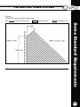
JVA ELECTRIC FENCE SYSTEMS
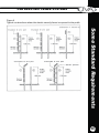
Figure 6
Typical constructions where the electric security fence is exposed to the public.
Some Standard Requirements
39
JVA ELECTRIC FENCE SYSTEMS
Some Standard Requirements
Figure 7
Typical fence constructions where the electric security fence is installed in windows
and skylights.
40
Key:
c Electric security fence
d
Physical barrier
JVA ELECTRIC FENCE SYSTEMS
Figure 8
Prohibited zone for pulsed conductors.
Key:
Electric security fence
Physical barrier
Prohibited zone
Some Standard Requirements
41
JVA ELECTRIC FENCE SYSTEMS
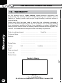
12. WARRANTY
All JVA products carry a against defective components and
workmanship. The warranty excludes damage caused by acts of Nature such as
* * * incorrect wiring.
Whilst every effort has been made to check that the information contained is
accurate, JVA Technologies (Pty) Ltd will not be liable to loss or damage resulting
from construction, operation or failure of any installation or system. Installation of
security electric fences should be made by trained professionals with regard to the
relevant local standards and workplace health and safety requirements.
Warranty
Product model purchased:
..................................
Serial No: ...........................
Customer Name:
..................................................................................................
Address:
..................................................................................................
..................................................................................................
..................................................................................................
Postal Code:
.......................................
Tel. No:
Cell: ................................
email:
..................................................................................................
Date purchased:
........................................
Invoice No:
........................................
Dealer Name:
..................................................................................................
Landline: ....................................
V
;=
X'*+
*+$!:JEMGFGZ,MC
42
JVA ELECTRIC FENCE SYSTEMS
43
JVA ELECTRIC FENCE SYSTEMS
!"#
INSTALLER DETAILS
CUSTOMISED CODES
Name ........................................................
Customer Pin No. ...................
Installer Pin No: ......................
44
Phone No. ................................................
Date Of Installation .................................
JVA ELECTRIC FENCE SYSTEMS
ANNOUNCING THE UPGRADE OF THE JVA Z18 TO THE JVA Z18 Mk2
We are delighted to inform you that JVA has produced a new improved version of the JVA Z18 – the JVA Z18 Mk2.
[
`
]
]
]
]
]
Bi-Polar operation – to enable all-live fences
3 relays on board – all programmable to monitor more and various conditions
Tamper/Safety switch detection – Checks if the lid is removed
Can also be operated from two keypads
And more general improvements to the product.
These improvements have occasioned some changes to the Z18 Manual. While the new manuals are being printed
[
upgraded model.
Page 5
3. SPECIFICATIONS
+
`
]
]
]
"[$
`
Energiser On – 870mA average, 1220mA peak
;
[
>[*{}}@
the recommended operating temperature is from -15°C to +50°C.
Page 6
4.2 High Voltage Terminals
Standard
Return
Earth
N/C
Feed
N/C
Earth
High Voltage (Fence) Terminals in Conventional Mode
BiPolar
RET 1+
EARTH
RET 2-
+FENCE
EARTH
High Voltage (Fence) Terminals in Bi-polar Mode
1
-FENCE
JVA ELECTRIC FENCE SYSTEMS
Page 8
]
]
]
4.4 Status Lights
[
X voltage falls below the Fence Alarm VoltageX
X
Fence and gate LEDs are latched on (like the strobe) until cleared, using the clear alarm memory sequence (*1#),
or until the energiser is rearmed.
4.5 Inputs and Outputs
New low voltage connector layout – Note the extra 3 relay outputs
Page 13
5.2 Example fence wiring diagram
Example Fence Wiring Diagram, Conventional – Live & Earth
2
JVA ELECTRIC FENCE SYSTEMS
Page 13
5.2 Example fence wiring diagram
Example Fence Wiring Diagram, Bi-polar – All Live
Page 17
7. TECHNICAL INFORMATION
+
&
[~<
>_
Page 18
]
7.2 Status Codes
=
<
Tamper detected. Corrective action is to Fit the lid.
7.3 Jumpers
]
]
Jumper J3 also disables the new infrared Tamper/Safety feature, if it has been enabled by programming sequence
168#.
The new Tamper/Safety circuit serves two functions. It protects service personnel from receiving a shock by
disarming the energiser when the lid is removed. It also sounds an alarm when the lid is removed while the
energiser is armed. The tamper alarm can be inhibited by shorting the J3 pins together. It should be noted that
%*
[
[
above the IR tamper circuit, and the Tamper function must have been enabled by programming sequece 168#.
Page 21
8.6.1 Power Level (01x#)
The Z18 Mk2 has improved programmable
voltage control indicated by this new table.
Table 16 – Power Level Values
Value (x)
Voltage
Conventional Mode
Voltage
Bi-Polar Mode
0
5.0kV
2.5kV
1
5.5kV
2.8kV
2
6.0kV
3.0kV
3
6.5kV
3.3kV
>
7.0kV
3.5kV
5
7.5kV
3.8kV
6
8.0kV
4.0kV
7
8.5kV
>%
8
9.0kV
>_%
9
9.5kV
>_%
3
JVA ELECTRIC FENCE SYSTEMS
Page 22
8.6.7 Battery Alarm Voltage (07x#)
The new default battery alarm voltage is 10 volts.
Page 24
8.6.14 Chime Mode (14x#)
Value
Note the changes to the chime mode functions in the new table.
If set to Siren, the beepers mimic the siren function. Gate Beeps
plus Siren["
'>
Close, plus a continuous beep for an alarm. The beeps are from
the keypad only, not from the internal beeper.
Function
0
None
1
Door Chime
2
Siren
3
Fence Alarm
>
Gate Beeps plus Siren
Auto Re-Arm Time (20x#)
This option sets the time which must elapse before another
~
completely through its cycles).
Value
If an event occurs (such as a low fence voltage) which triggers
the siren, any other events which would otherwise trigger the
siren (such as a gate alarm) will be ignored while the siren is
sounding and until after the Auto Re-arm time has passed.
Time
0
0 Seconds (Immediate)
1
30 Seconds
2
1 Minute
3
2 Minutes
4
3 Minutes
A setting of 9 will disable Auto Re-arm.
5
>
If this time is set to less than the Siren Off Time, the energiser
may re-arm in the Off time and the number of Siren Cycles will
be reduced.
6
5 Minutes
7
6 Minutes
8
7 Minutes
Setting 0 was changed to immediate in version 7.77.
9
Disabled – Do not auto rearm
Auto Re-arm Time Values (20x#)
Values for Firmware 7.77 and above
Page 25
8.6.16 Relay Functions
Value (x)
0
1
2
3
>
Some additional modes have been added to the relay
functions as per table.
%"`
]
]
]
]
]
Relay 1 – Siren
Relay 2 – Strobe
Relay 3 – Fence
>@
Relay 5 – General
Page 28
5
6
7
8
9
10
11
12
13
>
15
16
Mode
Fence 1
Fence 1 or off
Armed 1
Fence 2
Fence 2 or off
Armed 2
Fence Bi-Polar
General
Siren
Strobe
AC Fail
Low/Bad Battery
Tamper
Strobe 2
Gate 1 or 2
Siren caused by Gate 1 or 2
Armed in Low Power Mode
9. KEYPAD FEATURES
All JVA Z series energisers, including the Z18 Mk2, now have support for up to three keypads. If more than one
keypad is desired, one of the keypads must have an ID of 2. The other keypads can have an ID number from 1 to 8
but excluding ID 2. If only one keypad is desired, any ID number from 1 to 8 can be used.
4
JVA ELECTRIC FENCE SYSTEMS
Z-RANGE
Z14
RANGE FEATURES INCLUDE
Z14 STANDARD
AND BI-POLAR
ENERGIZERS
+ LCD voltage display
+ Powerful 4 joules per zone peak output energy
o
p
+ Designed to pass IEC60335.2.76 and EMC
9.2 9.0
+
Z18
Z18 STANDARD
AND BI-POLAR
ENERGIZERS
GSM MONITORS AND
CONTROLS JVA ENERGIZERS
USING A CELL PHONE
+
+
+
+
+
+
+
+
+
+
standards (reports available on request)
Wall mountable, robust enclosure with
detachable PCB chassis for ease of
installation and repair
Earth monitor input
Gate input
Key-switch
Keypad programmable
Lower-power mode
Entry/Exit delay from gate input trigger
Switched +12V outputs for Siren and
Strobe (up to 30 Watts for 3 minutes)
Microprocessor controlled
Outputs may be wired for BiPolar fences
(excluding Z28)
Multiple single-zone energizers can be
wired as a group
WEB SERVER MONITORS
AND CONTROLS
ENERGIZERS VIA THE
INTERNET
Z28
Z28 STANDARD
2-ZONE ENERGIZER
PERIMETER PATROL
COMPLETE CONTROL
SYSTEM MONITORING
EVENT LOGGING
Customer Support
For assistance: If you have any questions or need further assistance, please call your
nearest JVA dealer. SA Tel. No.: 0861 782 349.
For service or repairs: If a service or repair is required, please package and label your
energizer carefully and return it to your local JVA Service Centre.
For warranty repairs: Include proof of purchase, e.g. invoice.
Note: Repair centre details are displayed on the back cover of this manual.
JVA ELECTRIC FENCE SYSTEMS
JVA products are designed by JVA Technologies,
Queensland, Australia and distributed to:
AUSTRALIA
AFRICA
NEW ZEALAND
LATINO AMERICA
CARIBBEAN
SOUTH EAST ASIA
EUROPE
RUSSIA
INDIA
USA
MEXICO
CENTRAL ASIA
UNITED KINGDOM
JVA SA SERVICE CENTRES
East Rand (Jet Park)
Cape Town
Durban North
Aerostar Business Park
219 Jet Park Road, Jet Park
Tel: 011 397 3507
Unit 15, Viking Business Park
Viking Way, Epping Industria
Tel: 021 534 5056
North Rand (Kya Sand)
Polokwane
Shop 11, Arcadia Centre
87 Umhlanga Rocks Drive
Tel: 031 563 0274/
031 563 6478
174 Bernie Street
Randburg
Tel: 011 708 6442
19A Suez Street
Nirvana
Tel: 015 292 6273
Pietermaritzburg
West Rand (Roodepoort)
Nelspruit
Port Elizabeth
602 Ontdekkers Road
Delaréy, Roodepoort
Tel: 011 472 8823
D1 Waterfall Park
15 Rapid Street
Riverside Industrial Park
Tel: 013 752 7152
45 Mangold Street
Newton Park
Tel: 041 365 7178
1185 Steve Biko Road
(977 Voortrekker Road)
Wonderboom South
Tel: 012 335 4290
Bloemfontein
36 Kolbe Lane
Tel: 051 448 6695
Shop 3, Paphos Park
Devereaux Avenue
Tel: 043 726 6652/60
Pinetown
George
Kimberley
Unit 1, 7 Suffert Street
Tel: 031 702 6351
Shop 3, 57 York Road
George
Tel: 044 874 0669
Pretoria
29 Schmidtsdrift Road
Tel: 053 861 5631
Rustenburg
51 Winston Road
Tel: 033 342 6727
East London
1 Howick Avenue, Shop 7, Waterfall Mall
Tel: 014 537 2884
Nearest RSA branch: Website:e-mail: [email protected]