1
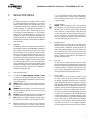
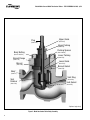
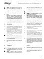
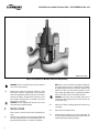
®
Valtek Control Products
Mark One and Mark Two Control Valves
FCD VLENIM0001-01-AQ – 08/14
Experience In Motion
USER INSTRUCTIONS
Installation
Operation
Maintenance
1
Valtek Mark One and Mark Two Control Valves FCD VLENIM001-01-AQ - 8/14
®
Contents
1.
2.
3.
4.
5.
6.
7.
8.
General Information
Unpacking
Installation
Quick Check
Valve Maintenance
Disassembly and Inspection
Assembly and Installation
Sever Service Trim Options
8.1 CavControl
8.2. ChannelStream
8.3. MegaStream
8.4. Stealth
8.5. TigerTooth
3
5
5
6
7
9
10
12
12
12
13
13
14
Figures
Figure 1 – Mark One Control Valve Body Assembly (optional angle body)
Figure 2 – Pressure Balanced Mark One Control Valve Body Assembly
Figure 3 – Exploded View Mark One Body Assembly
Figure 4 – Soft Seat Assembly
Figure 5 – Actuator Stem / Stem Clamp Alignment
Figure 6 – Mark One with CavControl Trim Body Assembly
Figure 7 – Mark One with ChannelStream Trim Body Assembly
Figure 8 – Mark One with MegaStream Trim Body Assembly
Figure 9 – Mark One with Stealth Trim Body Assembly
Figure 10 – Mark One with TigerTooth Trim Body Assembly
Tables
Table I – Common Lubricants
Table II – Suggested Bonnet Bolting Torque Values
Table III – Troubleshooting Chart
2
®
1.
Valtek Mark One and Mark Two Control Valves FCD VLENIM001-01-AQ - 8/14
General Information
1.1.Using
The following instructions are designed to assist in unpacking, installing and performing maintenance as required on
Flowserve products. Product users and maintenance personnel should thoroughly review this bulletin prior to unpacking,
installing, operating, or performing any maintenance. In
most cases, Flowserve valves, actuators and accessories
are designed for specific applications (e.g. with regard to
medium, pressure, and temperature). For this reason, they
should not be used in other applications without first contacting the manufacturer. The product Installation, Operation,
and Maintenance Instructions provides important additional
safety information.
1.2.Applicability
The following instructions are applicable to the maintenance
and installation of Flowserve Valtek Mark One and Mark Two
globe and angle body design control valves. These instructions cannot claim to cover all details of all possible product
variations, nor can they provide information for every possible example of installation, operation or maintenance. This
means that the instructions normally include only the directions to be followed by qualified personal using the product
for its defined purpose. If there are any uncertainties in this
respect, particularly in the event of missing product-related
information, clarification must be obtained via the appropriate Flowserve sales office. All Flowserve User Manuals are
available at www.flowserve.com.
1.3.
(e.g. in the operating instructions, product documentation,
or on the product itself) is essential, in order to avoid faults,
which can directly or indirectly cause severe personal injury
or property damage.
1.4.
Protective Clothing
DANGER: Flowserve products are often used in problematic applications (e.g. under extremely high pressures with
dangerous, toxic or corrosive mediums). When performing
service, inspection, or repair operations, always ensure that
the valve and actuator are depressurized and that the valve
has been cleaned and is free from harmful substances. In
such cases, pay particular attention to personal protection
(e.g. protective clothing, gloves, glasses etc.).
1.5.
Qualified Personnel
Qualified personnel are people who, on account of their
training, experience and instruction and their knowledge of
relevant standards, specifications, accident prevention regulations and operating conditions, have been authorized by
those responsible for the safety of the plant to perform the
necessary work and who can recognize and avoid possible
dangers. Contact your local Flowserve representation for a
schedule of training schools.
1.6.
Spare Parts
Use only Flowserve original spare parts. Flowserve cannot
accept responsibility for any damages that occur from using
spare parts or fastening materials from other manufactures.
If Flowserve products (especially sealing materials) have
been on store for long periods of time check them for corrosion or deterioration before putting them into use.
1.7.
Service / Repair
To avoid possible injury to personnel or damage to products, safety terms must be strictly adhered to. Modifying
this product, substituting non-factory parts, or using maintenance procedures other than those outlined in these Installation, Operation, and Maintenance Instructions could drastically affect performance, be hazardous to personnel and
equipment, and may void existing warranties. Between the
actuator and the valve there are moving parts. To avoid injury, Flowserve provides pinch-point-protection in the form
of cover plates, especially where side-mounted positioners
are fitted. If these plates are removed for inspection, service
or repair special attention is required. After completing work
the cover plates must be refitted. Apart from the operating
instructions and the obligatory accident prevention directives valid in the country of use, all recognized regulations
for safety and good engineering practices must be followed
Terms Concerning Safety
1.3.1.
The safety terms DANGER, WARNING, CAUTION and NOTE
are used in these instructions to highlight particular dangers
and/or to provide additional information on aspects that may
not be readily apparent.
DANGER: Indicates that death, severe personal injury and/or
substantial property damage will occur if proper precautions
are not taken.
WARNING: Indicates that death, severe personal injury and/
or substantial property damage can occur if proper precautions are not taken.
CAUTION: Indicates that minor personal injury and/or property damage can occur if proper precautions are not taken.
NOTE: Indicates and provides additional technical information, which may not be obvious, even to qualified personnel.
STOP!
1.3.2.
Compliance with other notes, which may not be particularly
emphasized, with regard to transport, assembly, operation
and maintenance and with regard to technical documentation
.
3
Valtek Mark One and Mark Two Control Valves FCD VLENIM001-01-AQ - 8/14
®
Upper Guide
Plug
(Item # 87)
(Item # 50)
Upper Packing
(Item # 88)
Body Bolting
Packing Spacers
(Item # 94-99)
(Item # 108/114)
Lower Packing
Bonnet Flange
(Item # 83)
(Item # 70)
Lower Guide
Bonnet
(Item # 83)
(Item # 40)
Bonnet Gasket
(Item # 58)
Body*
(Item # 1)
Seat Ring
Seat
Retainer
(Item # 20)
Seat Gasket
(Item # 30)
(Item # 55)
*Optional angle body
Figure 1: Mark One Control Valve Body Assembly
4
®
Valtek Mark One and Mark Two Control Valves FCD VLENIM001-01-AQ - 8/14
2.Unpacking
supply must be limited to less than 150 psi (10.3 bar). This
is indicated on a sticker found near the upper air port on
the actuator cylinder. An air regulator should be installed
to ensure the supply pressure does not exceed the actuator
design pressure indicated on the sticker.
CAUTION: Do not insulate extensions that are provided for
hot or cold services.
CAUTION: On valves equipped with air filters, the air filter
must point down to perform properly.
NOTE: Selecting the proper fastener material is the responsibility of the customer. Typically, the supplier does not know
what the valve service conditions or environment may be.
Flowserve‘s standard body bolting material is B7/2H. B8/8
(stainless steel) is optional for applications more than 800°
F / 425° C and with stainless steel or alloy body valves. The
customer therefore must consider the material‘s resistance
to stress corrosion cracking in addition to general corrosion.
As with any mechanical equipment, periodic inspection and
maintenance is required. For more information about fastener materials, contact your Flowserve representative.
2.1.
3.1.
Pipelines must be correctly aligned to ensure that the valve
is not fitted under tension.
3.2.
Fire protection must be provided by the user.
3.3.
Before installing the valve, clean the line of dirt, welding
chips, scale and other foreign material.
3.4.
Whenever possible, the valve should be installed in an
upright position. Vertical installation permits easier valve
maintenance. This is also important for cryogenic applications to keep the packing isolated from the flowing medium,
permitting the packing temperature to remain close to ambient temperature.
3.5.
Be sure to provide proper overhead clearance for the actuator to allow for disassembly of the plug from the valve
body. Refer to the appropriate actuator User Instructions for
proper clearances. Actuator User Instructions are available
at www.flowserve.com.
3.6.
Double-check flow direction to be sure the valve is installed
correctly. Flow direction is indicated by the arrow attached
to the body.
3.7.
If welding the valve into the line, use extreme care to avoid
excess heat buildup in the valve.
3.8.
If the valve has separable end flanges, verify that the half
rings are installed on the valve body before bolting the valve
into the line.
STOP!
WARNING: Before products are returned to Flowserve for
repair or service, Flowserve must be provided with a certificate that confirms that the product has been decontaminated and is clean. Flowserve will not accept deliveries if a
cleaning certificate has not been provided. Return authorization is also required before parts are returned. Contact your
local Flowserve representative to obtain return authorization.
1.8.Storage
In many cases, Flowserve products are manufactured from
stainless steel. Products not manufactured from stainless
steel are provided with an epoxy resin coating. This means
that Flowserve products are well protected from corrosion.
Nevertheless, Flowserve products must be stored adequately in a clean, dry environment. Plastic caps or plywood protectors are fitted to help protect the flange faces and prevent
the ingress of foreign materials. These caps should not be
removed until the valve is actually mounted into the system.
2.2.
STOP!
While unpacking the valve, check the packing list against the
materials received. Lists describing the valve and accessories are included in each shipping container.
When lifting the valve from shipping container, use straps
through the yoke legs, or the lifting lugs attached to the
body bolting for valves over four inch, or the adjusting
screw for valves four inch and under. Take care to position
lifting straps to avoid damage to the tubing, mounted accessories, or stroke plate.
WARNING: When lifting a valve be aware that the centre of
gravity may be above the lifting point. Therefore, support
must be given to prevent the valve from rotating. Failure to
do so can cause serious injury to personnel and damage to
the valve and nearby equipment.
2.3.
Contact your shipper immediately if there is shipping damage.
2.4.
Should any problem arise, call your Flowserve representative.
3.Installation
STOP!
DANGER: Before installation check the purchase order number, serial number, and/or the tag number to ensure that the
valve and actuator being installed are correct for the intended application.
WARNING: The maximum air supply for most Valtek cylinder actuators is 150 psi (10.3 bar). In some cases, the air
5
®
Valtek Mark One and Mark Two Control Valves FCD VLENIM001-01-AQ - 8/14
*Optional angle body
Figure 2: Pressure Balanced Mark One Control Valve Body Assembly
STOP!
3.9.
WARNING: Failure to install half rings on the valve body can
cause serious personal injury.
Connect the air supply and instrument signal lines. Throttling control valves are equipped with a valve positioner.
Refer to the appropriate positioner bulletin for connections,
maximum air supplies, and maintenance instructions. An air
filter should be installed before the positioner. All connections must be free of leaks.
CAUTION: On valves equipped with air filters, the air filter
must point down to perform properly.
4.Quick-check
4.1.
6
Prior to start-up, check the control valve by following these
steps:
Stroke the valve and observe the plug position indicator on
the stem clamp compared to the stroke indicator plate. The
plug should change position in a smooth, linear fashion.
STOP!
NOTE: Due to excessive friction a dry graphite packing can
cause the plug stem to move in a jerky fashion. Lubrication
of graphite packing will provide smoother stroking. Lubrication can be done by using a bonnet lubricator or by liberally coating each packing ring by hand during installation.
Please refer to Table I for lists of common lubricants.
WARNING: Keep hands, hair and clothing away from all
moving parts when operating the valve. Failure to do so can
cause serious injury.
4.2.
Check for full stroke by making appropriate instrument signal changes.
4.3.
Check all air connections for leaks.
4.4.
Check packing box bolting for the correct adjustment. Refer to the packing installation manual for specific details on
maintaining the style of packing supplied.
Valtek Mark One and Mark Two Control Valves FCD VLENIM001-01-AQ - 8/14
®
CAUTION: Do not overtighten packing. This can cause excessive packing wear, high stem friction that may impede plug
movement and can damage the packing. Over-tightening
packing will not improve the stem seal unless the packing
has been previously damaged. Damaged packing should be
replaced.
4.5.
Make sure the valve fails in the correct direction in case of air
failure. This is done by turning off the air supply and observing the failure direction.
5.
Valve Maintenance
At least once every six months, check for proper operation
by following the preventative maintenance steps outlined
below. These steps can be performed while the valve is inline and, in some cases, without interrupting service. If an
internal problem is suspected, refer to Section 6, Valve Disassembly and Inspection.
5.1.
Look for signs of gasket leakage through the end flanges and
bonnet. Re-torque flange and bonnet bolting (if required).
Refer to Table II for bonnet bolt torque values.
5.2.
Examine the valve for damage caused by corrosive fumes or
process drippings.
5.3.
Clean valve and repaint areas of severe oxidation.
5.4.
Check packing box bolting for proper tightness and packing
leakage. If packing leakage is noticed, packing maintenance
is required. Refer to the packing installation manual (document number VLAIM040) for specific details on maintaining
the style of packing supplied.
CAUTION: Do not overtighten packing. This can cause excessive packing wear and high stem friction that may impede
stem movement. Packing that is tightened too tight will typically not seal correctly.
5.5.
5.6.
STOP!
5.7.
If the valve is supplied with a lubricator fitting, check lubricant supply and add lubricant if necessary. See Table I for
common lubricants.
If possible, stroke the valve and check for smooth, fullstroke operation. Unsteady stem movement could indicate
an internal valve problem.
NOTE: Due to excessive friction a dry graphite packing can
cause the plug stem to move in a jerky fashion. Lubrication
of graphite packing will provide smoother stroking. Lubrication can be done by using a bonnet lubricator or by liberally coating each packing ring by hand during installation.
Please refer to Table I for lists of common lubricants.
WARNING: Keep hands, hair and clothing away from all
moving parts when operating the valve. Failure to do so can
cause serious injury.
Make sure positioner linkage and stem clamp are securely
fastened. If the stem clamp is loose, check plug thread engagement (refer to the “Reassembly and Installation” section for the correct procedure on aligning the plug with the
seat). Tighten stem clamp nut.
NOTE: Refer to the appropriate User Manuals when adjusting positioners and providing maintenance to actuators.
Current User Manuals are available at www.flowserve.com.
5.8.
Verify that the takeoff arm and follower arm are not binding
at either end of the stroke. The follower arm attached to the
positioner should be free to move slightly when the valve is
at both ends of the stroke.
5.9.
Ensure all accessories, brackets and bolting are securely
fastened.
5.10.
If possible, remove air supply and observe actuator for correct fail-safe action.
5.11.
Check rubber actuator bellows for splits, cuts or wear.
Table I: Common Packing Lubricants
Lubricant
Manufacturer
Krytox®
Temperature Range
Application Description
°F
°C
E.I DuPont
-5 to 550
-20 to 285
Fluorinated general purpose grease; handles common liquids and
gasses; good lubricity in harsh mediums; nonflammable, chemically
inert; will not harm plastic or metal parts
GP 460
Acheson Colloids
Company
32 to 1000
0 to 540
Graphite in petrolatum; high pressure; anti-galling; graphite remains
above 600°F / 316°C
725
Chesterton
32 to 2600
0 to 1425
Nickel, Aluminum and graphite in oil suspension; provides protection
with an ultra-thin coating of nickel particles
7
Valtek Mark One and Mark Two Control Valves FCD VLENIM001-01-AQ - 8/14
®
Gland Bolting
(Items #109, 117)
Gland Flange
(Item #80 )
Body Bolting
(Items #108, 114)
Bonnet Flange
(Item #70)
Upper Guide
Upper Packing
(Item #87)
(Item #88)
Packing Spacers
Lower Packing
(Item #88)
Yoke Half Clamps
& Yoke Clamp Bolts
(Items #76, 107,118)
(Item #94-99)
Lower Guide
(Item #83)
Bonnet
(Item #40)
Bonnet Gasket
(Item #58)
Plug
(Item #50)
Seat Retainer
(Item #30)
Seat Ring
Seat Gasket
(Item #20)
(Item #55)
Body
(Item #1)
*Optional angle body
Figure 3: Exploded View Mark One Body Assembly
8
®
5.12.
Valtek Mark One and Mark Two Control Valves FCD VLENIM001-01-AQ - 8/14
Spray a soap solution around the actuator cylinder retaining
ring and actuator stem guide to check for air leaks through
the O-rings.
5.13.
Clean any dirt and other foreign material from the plug stem.
5.14.
If an air filter is supplied, check and replace cartridge if necessary. Drain any moisture accumulated in the air filter.
6.
Valve Disassembly
6.1.
To disassemble the valve body, refer to Figures 1, 2 and 3
then proceed as follows:
WARNING: Depressurize line to atmospheric pressure and
drain all fluids before working on the valve. Failure to do so
can cause serious injury.
STOP!
6.2.
If valve is air-to-open, apply air under the piston to lift the
plug off the seat before taking the valve apart. If valve is airto-close, proceed to step 6.3.
6.3.
Remove the bonnet flange bolting and lift actuator, bonnet
and plug out of the valve. Once removed, the actuator, bonnet and plug assembly (called the top works) should be lowered and blocked to prevent rolling during the disassembly
of the top works.
WARNING: Danger exists in removing the actuator, bonnet
and plug, especially if a pressure balanced plug is used. The
pressure balanced sleeve may stick to the plug and fall during disassembly, causing possible serious injury and damage to the valve or nearby equipment. If sleeve is observed
sticking to the plug, steps 6.3.1 to 6.3.4 should be consulted.
CAUTION: Heavy actuators may require a hoist. Lift the valve
with the yoke legs using a lifting strap and a hoist. Great care
should be taken to lift the actuator and plug straight out of
the body to avoid damage to the plug and seat.
STOP!
6.3.1.
6.3.2.
6.3.3.
If the sleeve is observed sticking to the plug during removal,
fully extend the plug by applying air above the piston, allowing the sleeve to remain in the body and the bonnet to rise
above the body.
In the gap between the top of the sleeve and the bottom of
the bonnet, place wooden blocking of equal thickness in at
least three places. The wooden blocks must not extend in
far enough that they interfere with plug movement. The plug
must be allowed to stroke up to the bonnet.
By applying air below the piston, retract the plug until the
plug head is freed from the sleeve. Once the plug is free from
the sleeve, remove the plug and bonnet assembly from the
body.
6.3.4.
Lift the pressure balanced sleeve out of the valve body using
lifting points on the top of the sleeve.
NOTE: In many small Mark One valves, the seat retainer and
pressure balancer sleeve are one and the same part. In larger valves, there are separate pressure balancer sleeves and
seat retainers.
6.4.
Lift retainer, seat ring and gaskets free of the body. Care
must be taken not to damage the gasket surfaces in the body
when the gaskets are removed.
6.5.
Valves with soft seats (see figure 4) require the seat ring to
be inspected and possibly disassembled. Check to see that
seating surfaces on the plug and seat assemblies are free of
damage. If the seat insert is worn, remove it from the assembly. Since the plug seating surface does not come in contact
with the seat insert retainer, it is not necessary to correct any
minor damage to that part. The plug seating surface can be
re-machined to a 30 degree angle. Lapping is not required
when proper reassembly procedures are followed.
6.6.
Loosen the stem clamp and unscrew the plug from the actuator stem.
WARNING: Danger exists when working with large valves
and heavy parts. Take care to properly support large parts to
avoid damage to the parts of nearby equipment or personnel.
STOP!
Table II: Suggested Bonnet Bolting Torque Values
Bolt Size
(inches)
Bolt Size (inches) Bolt/Stud Material
Carbon Steel
Stainless Steel
ft-lbs
Nm
ft-lbs
Nm
5/8
80
108
50
68
3/4
140
190
90
122
7/8
230
312
150
203
1
350
475
220
298
1 1/8
510
691
330
447
1 1/4
730
990
460
624
1 3/8
990
1342
630
854
1 1/2
1320
1790
840
1139
1 5/8
1710
2318
1080
1464
1 3/4
2170
2942
1400
1898
1 7/8
2700
3661
1700
2305
2
3350
4542
2100
2847
2 1/4
4050
5491
2530
3430
2 1/2
4850
6576
3010
4081
3
7273
9861
5913
8017
* All values are ±10%
9
®
Valtek Mark One and Mark Two Control Valves FCD VLENIM001-01-AQ - 8/14
6.7.
6.8.
Soft Seat Retainer
Soft Seat
6.9.
Seat Ring
Figure 4: Soft Seat Assembly
STOP!
Check to see the seating surfaces on both the seat ring and
plug are free of damage to ensure tight shutoff. Make sure
the gasket surfaces on the seat ring, bonnet and body are
clean and undamaged. Examine the plug stem and bonnet
bore for scoring, scratches, pitting or other damage.
6.11.
Refer to the appropriate actuator User Manual for detailed
instructions on actuators.
7.
Assembly and Installation
10
To replace packing or change the packing box configuration,
push out packing, spacer and guides from underneath the
bonnet with a dowel around 0.13 inch (3.3 mm) larger in
diameter than the plug stem.
WARNING: For valves equipped with separable end flanges, do not machine body gasket surfaces. Machining could
cause failure of the separable flange lip causing end gasket
leakage and valve failure.
CAUTION: When using separable end flanges and spiral
wound gaskets, use gaskets with outer backup rings. Failure
to do so could result in excess stress in some applications.
6.10.
Figure 5: Actuator Stem / Stem Clamp Alignment
Remove the packing gland bolting, yoke clamps and remove
the actuator.
If the seat surfaces need re-machining, both surfaces on
plug and seat ring must be reworked. The seat angle on the
plug is 30 degrees (36 degrees for CavControl and ChannelStream valves); the seat ring, 33 degrees. Lapping is not
necessary if proper assembly procedures are followed.
CAUTION: If re-machining, protect the stem while turning.
Ensure concentration of the seat surface with the plug stem
(or outside diameter of the seat ring, if machining the seat)
NOTE: Separate User Manuals with instructions on assembling actuators, positioners and other equipment can be
found on www.flowserve.com. Review any relevant User
Manual before proceeding
NOTE: It is recommended that all soft goods are replaced
when rebuilding Mark One and Two control valves. Soft
goods include gaskets, pressure balanced seals, soft seat
inserts, guide liners and packing seats.
Replacing these parts helps to ensure proper functioning of
the control valve.
7.1.
To reassemble the valve body, refer to figures 1, 2 and 6 thru
9 and proceed as follows:
7.2.
If the packing has been removed, refer to the appropriate
packing User Manual (document number VLAIM040) and reinstall the packing and lower guide exactly as shown. Make
sure at least 1/8 inch is left at the top of the packing box for
the top guide to sit into the bonnet. Different packing spac-
®
Valtek Mark One and Mark Two Control Valves FCD VLENIM001-01-AQ - 8/14
ers permit a wide variety of packing configurations, such as
twin seal and vacuum-pressure packing.
CAUTION: Valves with extended bonnets or metal bellows
seals must not have lower packing installed. Instead, lower
packing rings should be installed with the upper set. Lower
packing installed in extended bonnets or metal bellows seal
valves will diminish the integrity of the packing assembly.
NOTE: Guide liners should be replaced each time the valve
packing is replaced. Do not rebuild the valve without the
correct guide liners.
7.3.
Re-insert the plug stem into the packing box, being careful
not to score the plug stem or the guides. Reinstall pressure
balanced seals if required.
7.4.
Turn actuator back onto the plug, without turning the plug
inside the bonnet. Make sure the gland flange and bonnet
flange are in place before engaging the plug stem and actuator stem threads. The gland flange chamfer must be face
down towards the valve body. Leave approximately three
to four plug stem threads exposed. Attach yoke clamp and
gland flange bolting. For valves with a 2-inch spud, be sure
the half rings are in place between the yoke and bonnet.
Firmly tighten yoke clamp bolting. The packing box nuts
should be just over finger tight.
NOTE: Do not allow the gland flange to contact and gall the
polished plug stem.
7.5.
Install new bonnet and seat gaskets with the bevelled edge
up for Teflon gaskets.
7.6.
Insert the seat ring into the body with the step side down.
When the seat ring is properly in place it will turn easily in
the body. Place the seat retainer into the body with the thin
end of the cathedral window down. Most retainers have an
arrow pointing up to verify correct installation. For pressure
balanced valves, install the pressure balanced sleeve gasket.
Ensure that severe service retainers are correctly indexed by
turning the retainer in the body. Correctly aligned retainers
should turn easily.
CAUTION: Installing seat retainers upside down can damage
the control valve parts.
CAUTION: Seat rings, retainers and pressure balanced
sleeves must be installed squarely into the body to function
correctly. To check to make sure the parts are installed correctly, rotate these parts a little by hand. The parts should
rotate freely without binding.
NOTE: When the seat retainer has only two ports, one of the
two ports should be aligned with the upper port of the body.
7.7.
Place air under the actuator piston on air-to-open valves to
retract the plug.
7.8.
Lower the plug and bonnet squarely into the body. Be care-
ful not to scratch or gall the plug as it enters the body.
7.9.
7.9.1.
7.9.2.
To properly align the seat ring and plug, first bring the bonnet bolting to finger-tightness.
With pneumatic actuators, apply air pressure above the piston to seat the plug in the seat ring. Proceed to step 7.10.
With electric or hydraulic actuators, move the actuator stem
down until it is completely extended. Next, retract the actuator stem 1/8 inch (3.2 mm). Install the stem clamp onto
the plug stem and actuator stem and tighten the associated
bolting. Move the actuator stem completely down. Adjust
actuator limit switches according to the actuator’s operating
manual. The actuator limit switches will need to be readjusted once the body bolting has been tightened.
NOTE: Step 7.10 applies only to valves with pneumatic actuators. If an electric or hydraulic actuator is used, return the
plug to the mid-stroke position and proceed to tighten.
CAUTION: Failure to return the plug to a mid-stroke position
(electric or hydraulic operators only) will cause damage to
the actuator and / or the valve during the bonnet tightening
sequence. This is due to the inability of most electric / hydraulic actuators to accommodate the 1/16 inch / 1.60 mm
back-drive during the tightening sequence.
7.10.
For air-to-close valves, skip this step and go to step 7.11. For
air-to-open valves, check for proper plug seating as follows:
When proper seating occurs, the bonnet flange will be forced
up against the finger-tight body bolting with such force that
it will be impossible to move the flange. If proper seating
does not occur, the bonnet flange can be wiggled with light
hand force for small valves and light wrench force for larger
valves. Should this occur, place air under the actuator piston
and retract the actuator to approximate mid-stroke position.
Turn the plug out of the actuator plug stem one additional
thread and repeat above seating procedure. When the bonnet flange becomes tight against the finger-tight body bolting, the plug is properly seated. If necessary, repeat above
procedure until proper seating occurs.
7.11.
Stroke the valve open and closed several times to center the
seat ring. Retract the plug (open position). Begin tightening
the bonnet flange bolting in a manner that will keep the bonnet flange square / parallel with the body. Tighten the first
bolt 1/6 turn, or one nut flat, then tighten the bolt directly
opposite 1/6 turn and so on around the flange. Firmly tighten all bolts evenly and completely to compress the bonnet
gasket and to seat the bonnet. Torque the bonnet bolts to
the suggested torque values in Table II. The bonnet will seat
metal to metal with the body when the bonnet bolts are correctly torqued into place
11
Valtek Mark One and Mark Two Control Valves FCD VLENIM001-01-AQ - 8/14
®
7.12.
Figure 6
Mark One with CavControl Trim Body Assembly
Apply air over the piston to seat the plug. For all throttling
valves, adjust the stem clamp so that with full instrument
signal to the positioner the full signal scribe line on the positioner cam points to the centre of the cam roller bearing.
CAUTION: Make sure the slots of the stem clamp are perpendicular to the bolting. See Figure 5.
NOTE: For on / off valves, the bottom of the stem clamp
should simply be lined up with the bottom of actuator stem
± 1/16 inch (1.6 mm).
7.13.
Tighten the stem clamp bolting. Proper tightness is important since this adjustment secures the actuator stem to the
plug stem. Adjust the stroke plate so the stem clamp points
to the “closed” position.
7.14.
If the valve has been taken out of the line, make sure the flow
arrow indicates proper flow direction upon reinstallation.
7.15.
Adjust and test all accessories.
8.
Severe Service Trim Options
8.1.CavControl
8.1.1. CavControl replaces the standard Mark One retainer with
a drilled, stepped-hole retainer, see Figure 6. The plug and
bonnet have dimensional differences from the standard
Mark One design. Assembly and disassembly of the valve
follows the standard procedures.
8.1.2.
CavControl retainers, plugs and seats should be examined
for excessive cavitation damage when disassembled. Holes
in the retainer should be checked for worn or eroded surfaces. Check for plugged holes in the retainer. Plugs and retainer mating surfaces should be examined for damage. Repair
and replacement of damaged parts is critical to maintaining
cavitation resistance.
CAUTION: To function properly, CavControl is always installed flow over.
8.2.ChannelStream
8.2.1. ChannelStream replace the standard retainer with multiple
sleeves pinned together, see Figure 7. The plug, seat ring,
and bonnet have dimensional differences from the standard
Mark One design. Assembly and disassembly of the valve
follows the standard procedures.
8.2.2.
Figure 7
Mark One with ChannelStream Trim Body Assembly
12
ChannelStream retainers, plugs and seats should be examined for excessive cavitation damage when disassembled.
The inner holes in the retainer should be checked for wear or
erosion, evidence of erosion should require that the retainer
is disassembled. Plugs and retainer mating surfaces should
®
Valtek Mark One and Mark Two Control Valves FCD VLENIM001-01-AQ - 8/14
be examined for damage. Repair and replacement of damaged parts is critical to maintaining cavitation resistance.
8.2.3.
ChannelStream retainers should be cleaned of debris whenever the valve is opened.
8.2.4.
Use the following steps if the retainer must be disassembled
to clean or inspect for damage. ChannelStream retainers in
pressure classes 900 and higher cannot be disassembled
in the field. Contact your local Flowserve representative for
service options.
8.2.4.1. Carefully grind away the small bead welds located on the
assembly pins near the top of the retainer. This will loosen
the pins which hold the retainer together. Using a punch,
locate the hole in the retainer opposite the pin and drive
each pin out of the retainer.
8.2.4.2. The retainer can now be inspected for damage or cleaned.
Figure 8
Mark One with MegaStream Trim Body Assembly
8.2.4.3. Reassemble the retainer sleeves and reinstall the pins making sure to leave an open hole opposite each pin so that the
pin can be driven out in the future. Apply a small (1/8 inch)
bead of weld to each pin to hold it in place.
NOTE: Do not weld more than the approved 1/8 inch. Excessive heat from the bead welds that are too large can disturb critical retainer tolerances. Use an appropriate weld
rod which is compatible with the retainer material. If uncertain, contact the factory.
CAUTION: To function properly, ChannelStream is always
installed flow over.
8.3.MegaStream
8.3.1.
MegaStream replaces the standard Mark One retainer with
a drilled hole retainer, see Figure 8. The plug and bonnet
are typically identical to the standard Mark One design. Assembly and disassembly of the valve follows the standard
procedures.
8.3.2.
Figure 9
Mark One with Stealth Trim Body Assembly
MegaStream retainers, plugs and seats should be examined for damage when disassembled. Holes in the retainer
should be checked for worn or eroded surfaces. Check for
plugged holes in the retainer. Multi-stage MegaStream retainers cannot be disassembled. Repair and replacement of
damaged parts is critical to maintaining noise control.
CAUTION: To function properly, MegaStream is always installed flow under.
8.4.Stealth
8.4.1. Stealth replaces the standard Mark One retainer with a
braised, stacked-disk retainer, see Figure 9. Several of the
parts, including the plug, seat ring and bonnet have dimen-
13
®
Valtek Mark One and Mark Two Control Valves FCD VLENIM001-01-AQ - 8/14
sional differences from the standard Mark One design. Assembly and disassembly of the valve follows the standard
procedures.
8.4.2.
8.4.3
Stealth retainers, plugs and seats should be examined for
damage when disassembled. Holes in the retainer should
be checked for worn or eroded surfaces. Check for plugged
holes in the retainer. Stealth retainers cannot be disassembled. Repair and replacement of damaged parts is critical to
maintaining noise control.
CAUTION: With rare exception, to function properly, Stealth
is always installed flow under.
When reinstalling Stealth retainers, care must be given to
orientating the retainer correctly. Stealth retainers have an
arrow that must be aligned with the valve outlet.
8.5.TigerTooth
8.5.1. TigerTooth replaces the standard Mark One retainer with a
welded or pinned, stacked-disk retainer, see Figure 10. Several of the parts, including the plug, seat ring and bonnet
have dimensional differences from the standard Mark One
design. Assembly and disassembly of the valve follows the
standard procedures.
8.5.2.
Figure 10
Mark One with TigerTooth Trim Body Assembly
14
TigerTooth retainers, plugs and seats should be examined
for damage when disassembled. The retainer should be
checked for worn or eroded surfaces. Check for debris
lodged in the retainer. Pinned TigerTooth retainers can be
disassembled and cleaned. Care should be taken when reassembling to stack up the discs in the same order. Each
disc has been etched with a number for that purpose. Welded TigerTooth retainers should not be disassembled outside
a qualified service centre. Repair and replacement of damaged parts is critical to maintaining noise and/or cavitation
control.
CAUTION: With rare exception, to function properly, TigerTooth is always installed flow under.
Valtek Mark One and Mark Two Control Valves FCD VLENIM001-01-AQ - 8/14
®
Table III: Troubleshooting Chart
Problem
Stem motion
impeded
Excessive seat
leakage
Inadequate flow
Plug slams
Probable Cause
Corrective Action
1. Over-tightened packing
1. Adjust the packing box nuts to slightly over finger-tight
2. Service temperature is beyond
operating limits of trim design
2. Reconfirm service conditions and contact factory
3. Inadequate air supply
3. Check for leaks in air supply or instrument signal system; tighten loose connections
and replace leaky lines
4. Malfunctioning positioner
4. Refer to positioner User Instructions
1. Improperly tightened bonnet
1. Refer to step 7.11 Assembly and Installation section for correct tightening procedure
2. Worn or damaged seat ring
2. Disassemble valve and replace or repair seat ring
3. Worn or damaged seat or bonnet
gasket
3. Disassemble and replace gaskets
4. Inadequate actuator thrust
4. Check for adequate air supply to actuator; if air supply is adequate, reconfirm
service conditions and contact factory
5. Incorrectly adjusted plug
5. Refer to steps 7.9 to 7.11 Assembly and Installation section for correct plug adjustment
6. Improper flow direction
6. Refer to original specifications or contact factory
7 Improper
.
handwheel adjust-ment
acting as a limit-stop
7. Adjust handwheel until plug seats properly
8. Worn or damaged pressure balanced seals
8. Disassemble and replace pressure balanced seals
9. Inadequate air supply pressure
9. Check for leaks in air supply or instrument signal system; tighten loose connections
and replace leaky lines
1. Improper plug adjustment, limiting
stroke
1. Refer to steps 7.9 to 7.11 Assembly and Installation section for correct plug adjustment
2. Malfunctioning positioner
2. Refer to positioner maintenance instructions
3. Service conditions exceed trim
design capacity
3. Verify service conditions and consult factory
4. Incorrect actuator stroke
4. Verify actuator stroke
5. Inadequate air supply pressure
5. Check for leaks in air supply or instrument signal system; tighten loose connections
and replace leaky lines
1.Incorrect plug adjustment al-lowing
improper cushion of air between
actuator piston and yoke
1. Refer to steps 7.9 to 7.11 Assembly and Installation section for correct plug adjustment
2. Inadequate air supply
2. Check air supply to actuator; repair leaks and remove any restrictions in supply line
3.Trim sized too large for flow rate
Valve does not fail 1. Incorrect flow direction
in correct position 2. Incorrect actuator fail direction
3. Verify the service conditions and actuator sizing, install reduced trim
1. Reconfirm direction and, if necessary, correct flow direction through valve
2. Consult actuator User Manual and change fail direction
15
®
USA
Flowserve Flow Control Division
1350 N. Mt. Springs Parkway
Springville, UT 84663
USA
Phone: +1 801 489 8611
Fax: +1 801 489 3719
Austria
Flowserve Control Valves GmbH
Kasernengasse 6
9500 Villach
Austria
Phone: 43 (0) 4242 41 181 0
Fax: 43 (0) 4242 41181 50
France
Flowserve France S.A.S.
BP 60 63307 Thiers Cedex
France
Phone: 33 4738 04266
Fax: 33 4738 01424
FCD VLENIM0001-01-AQ Printed in USA. 08/14 (Replaces VLAIM001-00)
To find your local Flowserve representative:
For more information about Flowserve Corporation, visit
www.flowserve.com or call USA 1 800 225 6989
Flowserve Corporation has established industry leadership in the design and manufacture of its products. When properly selected, this Flowserve product is designed to
perform its intended function safely during its useful life. However, the purchaser or user of Flowserve products should be aware that Flowserve products might be used in
numerous applications under a wide variety of industrial service conditions. Although Flowserve can (and often does) provide general guidelines, it cannot provide specific data
and warnings for all possible applications. The purchaser/user must therefore assume the ultimate responsibility for the proper sizing and selection, installation, operation, and
maintenance of Flowserve products. The purchaser/user should read and understand the Installation Operation Maintenance (IOM) instructions included with the product, and
train its employees and contractors in the safe use of Flowserve products in connection with the specific application.
While the information and specifications contained in this literature are believed to be accurate, they are supplied for informative purposes only and should not be considered
certified or as a guarantee of satisfactory results by reliance thereon. Nothing contained herein is to be construed as a warranty or guarantee, express or implied, regarding any
matter with respect to this product. Because Flowserve is continually improving and upgrading its product design, the specifications, dimensions and information contained
herein are subject to change without notice. Should any question arise concerning these provisions, the purchaser/user should contact Flowserve Corporation at any one of its
worldwide operations or offices.
© 2014 Flowserve Corporation, Irving, Texas, USA. Flowserve is a registered trademark of Flowserve Corporation.
16
India
Flowserve India Controls Pvt Ltd.
Plot # 4, 1A, Road #8 EPIP
Whitefield
Bangalore, Karnataka, 560066
India
Phone: 91 80 40146200
Fax: 91 80 28410286
China
Flowserve Fluid Motion and
Control (Suzhou) Co., Ltd.
No. 35, Baiyu Road
Suzhou Industrial Park, Suzhou
Jiangsu Province, P.R. 215021
China
Phone: 86 512 6288 8790
Fax: 86 512 6288 8736
Singapore
Flowserve Pte. Ltd.
12 Tuas Avenue 20
Republic of Singapore 638824
Phone: 65 6879 8900
Fax: 65 6862 4940
Saudi Arabia
Flowserve Abahsain Flow Control
Co., Ltd.
Makkah Road, Phase 4
Plot 10 & 12, 2nd Industrial City
Damman, Kingdom of Saudi
Arabia
Phone: +966 3 857 3150 ext. 243
Fax: +966 3 857 4243