1
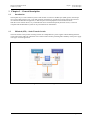
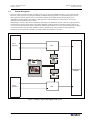
HIPULSE UPS SYSTEM HiSynch (LBS) User Manual Manuale Utente Bedienerhandbuch Manuel de l’utilisateur Manual del Usuario Gebruikershandleiding Manual Reference: 6223010O-2 (03/03) Hipulse UPS System USER MANUAL Load Bus Sync (LBS) Safety Precautions WARNING Personnel operating on any apparatus referred in this manual must know extensively the product. The UPS must be commissioned and serviced by an engineer approved by the manufacturer (or his agent). Failure to do so could result in personnel safety risk, equipment malfunction and invalidation of warranty. CONFORMITY AND STANDARDS The optional device complies with the requirements of the standards identified at the beginning of the User’s Manual supplied with the UPS Continued compliance requires installation in accordance with these instructions and the use of manufacturer approved accessories only. General The unit must be grounded in accordance with current electrical regulations. General As with other types of power equipment, dangerous voltages are present within the UPS enclosure. The risk of contact with these voltages is minimized as the live component parts are housed behind a hinged, lockable door. No risk exists to any personnel when operating the equipment in the normal manner, following the recommended operating procedures. All equipment maintenance and servicing procedures involve internal access and should be carried out only by trained personnel. Guide to the Instructions The warning triangle indicates all the personal safety instructions. Follow these instructions carefully to avoid injury. Page ii (03/03) USER MANUAL Hipulse UPS System Load Bus Sync (LBS) Table of Contents 1 Chapter 1 – General description ............................................................................................................................... 1-1 1.1 Introduction ............................................................................................................................................................... 1-1 1.2 HiSwitch (STS) – Static Transfer Switch................................................................................................................. 1-1 1.3 System Description ................................................................................................................................................... 1-2 1.4 Theory of operation................................................................................................................................................... 1-5 1.4.1 General Description ......................................................................................................................................... 1-5 1.4.2 Load Bus Sync circuit ...................................................................................................................................... 1-5 1.4.3 System Operation ............................................................................................................................................. 1-5 1.5 Operation................................................................................................................................................................... 1-6 1.5.1 Operator Controls............................................................................................................................................. 1-6 1.5.2 Operator Procedures......................................................................................................................................... 1-6 2 Chapter 2 – Installation (Mechanical) ...................................................................................................................... 2-1 2.1 Introduction ............................................................................................................................................................... 2-1 2.2 Composition of a LBS kit ......................................................................................................................................... 2-1 2.3 LBS Interface kit....................................................................................................................................................... 2-1 2.3.1 Physical location .............................................................................................................................................. 2-1 2.3.2 Cable entry ....................................................................................................................................................... 2-1 2.4 LBS Interface Box for single module or multimodule Hipulse with MSS.............................................................. 2-2 2.5 LBS Interface Box for 1+N Hipulse UPS System (without MSS).......................................................................... 2-3 2.6 LBS Control Panel Box ............................................................................................................................................ 2-4 3 Chapter 3 - Installation (Electrical)........................................................................................................................... 3-1 3.1 Electrical connections ............................................................................................................................................... 3-1 3.2 Settings ...................................................................................................................................................................... 3-1 3.2.1 Connection within the UPS/MSS cabinet........................................................................................................ 3-2 4 Chapter 4 - Specification .......................................................................................................................................... 4-1 4.1 Technical Characteristics .......................................................................................................................................... 4-1 25 Installation Drawings – Disegni d’installazione – Installationszeichnungen - Dessins de l’installation – Planos de Instalación – Installatietekeningen.......................................................................................................................... 25-1 (03/03) Page iii Hipulse UPS System USER MANUAL Load Bus Sync (LBS) This manual describes the following equipment: EQUIPMENT PART NUMBER Single and multimodule UPS configuration (with MSS): LBS kit 4645334S LBS Panel Control Box 4671002Y 1+N configuration (without MSS): LBS kit 4645338W LBS Panel Control Box 4671002Y Page iv (03/03) Hipulse UPS Installation Manual Load Bus Sync (LBS) Chapter 1 - General Description System Description 1 Chapter 1 – General description 1.1 Introduction The simplest way to create a dual-bus system is with Liebert’s exclusive Load Bus Sync (LBS) option, which keeps two or more UPS systems in sync, even when operating on batteries or asynchronous gensets. Each UPS powers its own downstream distribution equipment, so that each piece of load equipment can be connected to both. With the correct transfer devices, any connected load can be switched transparently between sources, so that one complete UPS and distribution system can be powered down for maintenance. 1.2 HiSwitch (STS) – Static Transfer Switch The static transfer switch permits switching between two independent AC power supplies without shutting down the critical load. Liebert offers the ‘HiSwitch’ line of static transfer switches permitting full availability of the power supply in all types of critical application. Figure 1-1 LBS and STS block diagram (03/03) Page 1-1 Chapter 1 - General Description Theory of operation 1.3 Hipulse UPS Installation Manual Load Bus Sync (LBS) System Description When two UPSs are tied to the same input and bypass sources, they will automatically stay in sync. with each other. However, if the systems are operating on batteries, on different backup generators or asynchronous bypass sources, their outputs will tend to drift out of sync. The Liebert Load Bus Sync (LBS) option keeps the output of two independent Uninterruptible Power Supply (UPSs) Systems in synchronisation even when the two systems are operating from two different power sources. Maintaining is critically important for installations with dual power distribution systems. These sites typically feature Liebert Precision Power Centers (PPC) with Liebert Static Bus Transfer Switches. Each PPC has dual inputs: it can receive power from either UPS systems, and switch seamlessly between the two as long as the UPS outputs are held in close synchronisation. This provides redundancy down to the PPC level. It also permits one entire half of the distribution system (upstream of the PPC) to be taken offline for maintenance of repairs. INPUT SOURCE 1 UPS Synchronised Outputs INPUT SOURCE 2 UPS Figure 1-2 LBS for single module Hipulse UPS system Page 1-2 (03/03) Hipulse UPS Installation Manual Load Bus Sync (LBS) Chapter 1 - General Description System Description UPS MAIN STATIC SWITCH (MSS Cabinet) INPUT SOURCE 1 UPS Synchronised Outputs INPUT SOURCE 2 UPS MAIN STATIC SWITCH (MSS Cabinet) UPS Figure 1-3 LBS for multimodule Hipulse UPS system (with MSS) (03/03) Page 1-3 Chapter 1 - General Description Theory of operation Hipulse UPS Installation Manual Load Bus Sync (LBS) INPUT SOURCE n UPS n LOAD 2 INPUT SOURCE 2 UPS Synchronised Outputs INPUT SOURCE 1 UPS LOAD 1 INPUT SOURCE n UPS n Figure 1-4 LBS for 1+N Hipulse UPS system (without MSS) Page 1-4 (03/03) Hipulse UPS Installation Manual Load Bus Sync (LBS) 1.4 Chapter 1 - General Description System Description Theory of operation 1.4.1 General Description The Liebert Load Bus Sync (LBS) option works by bringing together the synchronising reference signals of the two UPS Systems. Furthermore, the LBS is dormant until the two UPS systems drift more than a predetermined amount out of synchronisation. There are no additional connections between the logic controls of either systems which ensures maximum system independence and reliability. 1.4.2 Load Bus Sync circuit The LBS option consists mainly of: two different types of Interface Box located outside of each UPS system, the Control Panel Box, and the components assembled inside the UPS/MSS, described in subsequent chapters. The Interface Boxes have different mechanical properties depending on the system configuration in use. The control panel box, on the other hand, is the same for all configurations. Front panel controls are simple and fault tolerant. They enable the operator to select: 1) Whether the circuit will function automatically or switch set to ‘Off’. 2) Whether UPS System #1 or UPS System #2 will be the Designated Master System (DMS). The other UPS system by default then becomes the Designated Slave System (DSS). 1.4.3 System Operation The LBS option performs the following functions: 1) Continuously senses the phase relationship between the outputs of the two UPS systems that make up the system. 2) If the two systems lose synchronisation with each other for more than a predetermined period of time (adjustable 0.1 to 5 seconds), the LBS will synchronise the Designated Slave System (DSS) to the Designated Master System (DMS) if the Auto/Off switch is in the Auto position. DSS and DMS are selected manually via the master system select switch. If the DSS is on bypass and unable to synchronise to the DMS, the DMS will then synchronise to the output bus of the DSS. This re-selection of master will be accomplished automatically. 3) Continuously monitors the quality and sync of the bypass input voltage to both systems. Once quality and synchronisation between the two have been re-established for five seconds, the LBS will revert to separate synchronisation sources for both systems, each synchronised to its own bypass. 4) DSS and DMS are selected manually using the Master Select switch. If the Slave (DSS) is on bypass and cannot be synchronised with the Master (DMS), the DMS is synchronized with the Slave (DSS) output. This reselection of the Master is automatic. The box contains the terminal boards and fuses for reference signals for synchronizing the two UPSs. 5) Failure of any part of the LBS controls will not cause system failure. The worst case effect of a failure in the LBS will be a failure of the two systems to synchronise with each other during times when both systems are not synchronised to utility power. (03/03) Page 1-5 Chapter 1 - General Description Theory of operation 1.5 Hipulse UPS Installation Manual Load Bus Sync (LBS) Operation 1.5.1 Operator Controls Operation of the LBS has deliberately been kept as simple as possible. There are only three controls and five indicator lights on the LBS enclosure. The indicators are: LBS Indicator LBS Enabled Description Indicates that the load bus synchronisation circuitry is in the Automatic mode. Load 1 Sync to Load 2 Indicates that the DSS is no longer in synchronisation with the DMS. This alarm will indicate during the transition from internal bypass sync to DMS synchronisation sources. Indicates that the LBS circuitry has taken over the synchronisation of the UPS. If the System Non-Sync. indicator is also on, it means that synchronisation is in process. Indicates that the UPS critical bus is synchronised to the bypass input of the DMS, in this case UPS System #2. This indicator will turn on when the synchronisation process is Load 2 Sync to Load 1 Indicates that the UPS critical bus is synchronised to the bypass input of the DMS, in this case UPS System #1. This indicator will turn on when the synchronisation process is System Non-Sync. LBS Active complete. complete. Table 1-1 LBS Indicators Note: all indicators mentioned above can be supplied with Form C dry contacts for remote monitoring (refer to figure 25.1.3). Standard LBS controls are: LBS Controls Mode Select Switch Master Select Switch Lamp test Description Provides manual selection of automatic operation or ‘Off’ modes. In the Automatic mode, the LBS will be enabled. In the ‘Off’ mode, both UPS System will synchronise independently. Provides manual selection of the DMS source. The LBS circuitry will automatically switch DMS sources should the initially selected DMS lose its bypass input. Push this button to test indicator lights. Table 1-2 Standard LBS Controls 1.5.2 Operator Procedures The only two operator controls are the Mode Select Switch and the Master Select Switch. The Mode Select Switch can be left in the ‘Auto’ position all the time. The “Off” position can be selected at times when it is desired to let the UPS systems synchronise independently. The Master Select Switch allows the operator to choose which UPS bypass source will provide the reference synchronisation signal. In normal operation, both UPS systems will be functioning and the LBS Master Select Switch will be in the Automatic position. The LBS Enable indicator will be lighted, as will one of the indicators for Load X Sync to Load Y. If the two UPS drift out of synchronisation (while on generator or battery, for example), the LBS Active and System Non-Sync. indicators will be lighted. The Load X Sync to Load Y indicator will be off during the synchronisation process and turn back on when the process is complete. Page 1-6 (03/03) Hipulse UPS Installation Manual Load Bus Sync (LBS) Chapter 2 - Installation Procedure Installation (Mechanical) 2 Chapter 2 – Installation (Mechanical) 2.1 Introduction The LBS system may be requested as an option for instalment in the factory or in the form of a kit for installation on Liebert UPS devices previously installed. The LBS option is part of a family of products for control of UPS systems, and is guaranteed by an extensive customer service network. Factory installation of the LBS option includes assembly of internal UPS/MSS components (HV terminal board and Interface board). If field installed, the option kit on the UPS System must be mounted by an engineer approved by the manufacturer (or his agent). Contact Liebert Hiross Services at the address given in the start of this manual, regarding installation, operation, or warranty issues. WARNING Do not apply electrical power to the LBS equipment before the arrival of the commissioning engineer. Personnel operating on any apparatus referred in this manual must know extensively the product. 2.2 Composition of a LBS kit The kit P/N 4645334S (*)(for single HIPULSE UPS or multimodule with MSS) comprises: ♦ kit connection LBS-Hipulse P/N 4645325J ♦ P/N 4645005B: contains Interface Board, flat-cable and accessories ♦ LBS Interface box P/N 4671001X (*) the quantity to be specified for connection of the P/N 4645334S kit with HIPULSE UPS or multimodule with MSS is two units. N°1 LBS Panel Control box P/N 4671002Y The kit P/N 4645338W (**) (for 1+N HIPULSE UPS without MSS) comprises: ♦ (**) LBS Interface box P/N 4671004A ♦ (**) kit connection LBS-Hipulse P/N 4645325J (**) the quantities to be specified for connection of the P/N 4645338W kit are determined by the number of UPSs that make up the 1+N HIPULSE UPS system without MSS. 2.3 LBS Interface kit 2.3.1 Physical location The auxiliary terminal board X3 and the Interface board are located inside the UPS/MSS behind a protective metal cover. The auxiliary terminal board on the MSS is named X1. Note: Internal kit components are considered to have been factory installed. If this is not the case, refer to the detailed information supplied in the technical assistance installation manuals. 2.3.2 Cable entry Cables must be introduced through the openings provided for the purpose in the lower part of the cabinets. For more information, refer to the description and descriptive drawings provided in the UPS Users’ Manual. Cables from the LBS Interface box must be inserted from above or below, removing the covering plate. A hole must be made in the LBS control panel box to allow for cable connections. (03/03) Page 2-1 Chapter 2 - Installation Procedure Installation (Mechanical) 2.4 Hipulse UPS Installation Manual Load Bus Sync (LBS) LBS Interface Box for single module or multimodule Hipulse with MSS Figure 2-1 LBS Interface box for HIPULSE UPS or multimodule with MSS (P/N 4671001X) 1) All dimensions are in millimeters. 2) Refer to load bus sync control wiring lists (see figure 25.1.1) for wiring connection details. 3) Installation and service access required from front only. Page 2-2 (03/03) Hipulse UPS Installation Manual Load Bus Sync (LBS) 2.5 Chapter 2 - Installation Procedure Installation (Mechanical) LBS Interface Box for 1+N Hipulse UPS System (without MSS) Figure 2-2 LBS Interface box for 1+N HIPULSE UPS without MSS (P/N 4671004A) 1) 2) 3) 4) 5) All dimensions are in millimeters. Refer to load bus sync control wiring lists (see figure 25.1.2) for wiring connection details. Installation and service access required from front only. In the parallel 1+N configuration, the last Interface Box must have a U-bolt of 7 to 8 TB28-LV. Fuse holders F4,5,6 and N must be closed only on the Interface Boxes which are directly connected up to the LBS Control Panel box, while fuse holders F4,5,6 and N must be open for the remaining boxes. (03/03) Page 2-3 Chapter 2 - Installation Procedure Installation (Mechanical) 2.6 Hipulse UPS Installation Manual Load Bus Sync (LBS) LBS Control Panel Box Figure 2-3 LBS Control Panel box (P/N 4671002Y) Notes: 1) All dimensions are in millimeters. 2) Refer to load bus sync control wiring lists (see Chapter 25) for wiring connection details. 3) Installation and service access required from front only. 4) Holes must be made in the LBS control panel box as required for the cables to be introduced. Page 2-4 (03/03) Hipulse UPS Installation Manual Load Bus Sync (LBS) Chapter 3 - Installation Procedure Installation (Electrical) 3 Chapter 3 - Installation (Electrical) The LBS requires «control» cabling. All «control» cables (supplied by others) must be run separate from power cables in steel conduit. 3.1 Electrical connections Identify the wiring diagram in the Chapter 25, depending on the configuration of your system. WARNING Control wiring runs should not be combined in the same conduit. Separate cable groups, indicated by connection to TB26, TB28 and TB27, TB29. The wiring connections of the LBS system must be done with respect to the following notes: 1) Maximum cable length 150 metres with 2.5 sq. mm flexible stranded cable. 2) All wiring must be in accordance with local and national code practices. 3) Signal voltage for: TB26/TB28 – 24 Vdc, current 100 mA - TB27/TB29 – 400 Vca, current 100 mA - TB1 – 120 Vca, current 500 mA. 4) Electrical connections exiting the box are made using the screw terminal board. NOTE The LBS boxes must be grounded in accordance with current electrical regulations. 3.2 Settings 1) In the parallel 1+N configuration, the last Interface Box must have a U-bolt of 7 to 8 TB28-LV. Fuse holders F4,5,6 and N must be closed only on the Interface Boxes which are directly connected up to the LBS Control Panel box, while fuse holders F4,5,6 and N must be open for the remaining boxes. 2) In a parallel 1+N configuration with an external maintenance bypass (with Q3 in the UPS which is not present or is de-activated), make the connection between the UPS and the Interface Box as shown in details ‘A’ and ‘B’ in figure 25.1.2. (03/03) Page 3-1 Chapter 3 - Installation Procedure Installation (Electrical) 3.2.1 Hipulse UPS Installation Manual Load Bus Sync (LBS) Connection within the UPS/MSS cabinet WARNING The operations described in the paragraphs that follow must be carried out by authorized electricians or by technical personnel. If you have any difficulties do not hesitate to contact our Customer Service & Support department at the address given at the beginning of this manual. The constructor shall not be liable for consequential damages to the equipment or person based on wrong connections or operations non specifically set forth. Before installing the cable (user supplied) to the Hipulse UPS/MSS, it is necessary to remove power from the UPS System. To maintain continuity of supply, the load should first be transferred to the maintenance bypass circuit following the procedure given in the UPS user manual. Refer to the corresponding drawings, attached, in order to identify the physical location of the terminal boards in the UPS\MSS. Before making electrical connections, also refer to the diagrams in the Chapter 13, depending on the system configuration in use. 1) Remove the protective covers. 2) Verify that on the Alarm Interface Board (P/N 4590055P) jumper is setting on X6 1-2. 3) Connect the auxiliary cables (refer to figure in the Chapter 25) from LBS Interface Boxes to UPS\MSS terminal blocks. 4) Fix the outgoing auxiliary cable, following the cable way, using cable ties. Cables must be introduced through the openings provided in the lower part of the cabinets. 5) Connect up auxiliary cables between the Interface box and the LBS Control Panel box (refer to figure in the Chapter 25). 6) Replace the metal covers removed. Note: Internal kit components are considered to have been factory installed. If this is not the case, refer to the detailed information supplied in the technical assistance installation manuals. Page 3-2 (03/03) Hipulse UPS Installation Manual Load Bus Sync (LBS) Chapter 4 – ‘Specification’ 4 Chapter 4 - Specification 4.1 Technical Characteristics LBS INTERFACE BOX MECHANICAL CHARACTERISTICS UNITS P/N 4671001X P/N 4671004A Height mm 500 600 Width mm 400 400 Depth mm 150 200 Weight kg 12 17 Colour RAL 7032 Wall mounting (4 holes ∅ 10) Installation Cable entry - Top and bottom (by removable plate) UNITS P/N 4671002Y Height mm 610 Width mm 508 Depth mm 168 Weight kg 25 LBS CONTROL PANEL BOX MECHANICAL CHARACTERISTICS Wall mounting (4 holes ∅ 8) Installation Colour Cable entry IBM Off-white - User to size and cut holes for the cables to be used (03/03) Page 4-1 Chapter 4 – ‘Specification’ Hipulse UPS Installation Manual Load Bus Sync (LBS) This page is left blank intentionally Page 4-2 (03/03) Hipulse UPS Installation Manual Chapter 25 – Installation Drawing Load Bus Sync (LBS) 25 Installation Drawings – Disegni d’installazione – Installationszeichnungen Dessins de l’installation – Planos de Instalación – Installatietekeningen 25.1.1 25.1.2 25.1.3 25.1.4 25.1.5 25.1.6 25.1.7 25.1.8 25.1.9 25.1.10 25.1.11 25.1.12 25.1.13 LBS for Single module or multimodule (with MSS) Hipulse UPS System – LBS per configurazione singolo o parallelo multimodulo con ISR esterno - LBS für die Einzelkonfiguration oder parallelgeschaltet mit Multimodul und externem MSS - LBS pour configuration simple ou parallèle multi-module avec MSS externe - LBS para configuraciones simples o paralelo multimódulo con MSS exterior - LBS voor enkele of parallelle multimodule configuratie met externe MSS. LBS for 1+N Hipulse UPS System (without MSS) - LBS per configurazione parallelo 1+N (senza ISR) - LBS für Konfiguration 1+N (ohne MSS) - LBS pour configuration 1+N (sans MSS) - LBS para configuración 1+N (sin MSS) - LBS voor configuratie 1+N (zonder MSS). LBS Hipulse UPS System – detail of alarm status – dettaglio sullo stato dei contatti di allarme - Detail zum Zustand der Alarmkontakte - Détail sur l’état des contacts d’alarme - Detalle sobre el estado de los contactos de alarmas - Detail over de status van de alarmcontacten. details of kit connection LBS-Hipulse P/N 4645325J LBS-Hipulse P/N 4645325J = location of the kit inside the 80 kVA UPS - Localizzazione del kit all'interno dell'UPS da 80 kVA - Position des Kits im Innern des Schrankes für 80 kVA USV - Emplacement du kit à l'intérieur de l'armoire 80 kVA ASI - Ubicación del kit en el interior del armario 80 kVA UPS - Locatie van de set in de kast van de UPS 80 kVA location of the kit LBS-Hipulse P/N 4645325J inside the 120/160/200 kVA UPS location of the kit LBS-Hipulse P/N 4645325J inside the 300 kVA UPS location of the kit LBS-Hipulse P/N 4645325J inside the 400 kVA UPS location of the kit LBS-Hipulse P/N 4645325J inside the 600 kVA UPS location of the kit LBS-Hipulse P/N 4645325J inside the 800 kVA UPS location of the kit LBS-Hipulse P/N 4645325J inside the 250 kVA MSS location of the kit LBS-Hipulse P/N 4645325J inside the 400/600/800 kVA MSS location of the kit LBS-Hipulse P/N 4645325J inside the 1200 kVA MSS (03/03) Page 25-1 Chapter 25 – Installation Drawing Hipulse UPS Installation Manual Load Bus Sync (LBS) 25.1.1 LBS for Single module or multimodule Hipulse UPS System– Electrical connections Page 25-2 (03/03) Hipulse UPS Installation Manual Chapter 25 – Installation Drawing Load Bus Sync (LBS) 25.1.2 LBS for 1+N Hipulse UPS System (without MSS) – Electrical connections (03/03) Page 25-3 Chapter 25 – Installation Drawing Hipulse UPS Installation Manual Load Bus Sync (LBS) 25.1.3 LBS Hipulse UPS System – detail of alarm status Page 25-4 (03/03) Hipulse UPS Installation Manual Chapter 25 – Installation Drawing Load Bus Sync (LBS) 25.1.4 n o p q LBS Hipulse UPS System – details of kit connection LBS-Hipulse P/N 4645325J TB-HV =Terminal block – Morsettiere – Klemmbretter – Borniers – Tableros de bornes – klemmenblokken X3 UPS/USV/ASI (X1-MSS) = Terminal block – Morsettiera ausiliaria – Zusätzlicher Anschlußblock – Bornier aux. – Hulpaansluitklemmenblok P/N 45500055P = Interface brd – Sch. Interfaccia – Schnittstellenkarte – Carte d'interface – Tarjeta Interfaz – Interfacekaart Control wiring ( by others) to LBS Interface box P/N 4671001X (03/03) Page 25-5 Chapter 25 – Installation Drawing Hipulse UPS Installation Manual Load Bus Sync (LBS) 25.1.5 LBS Hipulse UPS System – location of the kit LBS-Hipulse P/N 4645325J inside the 80 kVA UPS Page 25-6 (03/03) Hipulse UPS Installation Manual Chapter 25 – Installation Drawing Load Bus Sync (LBS) 25.1.6 LBS Hipulse UPS System – location of the kit LBS-Hipulse P/N 4645325J inside the 120/160/200 kVA UPS (03/03) Page 25-7 Chapter 25 – Installation Drawing Hipulse UPS Installation Manual Load Bus Sync (LBS) 25.1.7 LBS Hipulse UPS System – location of the kit LBS-Hipulse P/N 4645325J inside the 300 kVA UPS Page 25-8 (03/03) Hipulse UPS Installation Manual Chapter 25 – Installation Drawing Load Bus Sync (LBS) 25.1.8 LBS Hipulse UPS System – location of the kit LBS-Hipulse P/N 4645325J inside the 400 kVA UPS (03/03) Page 25-9 Chapter 25 – Installation Drawing Hipulse UPS Installation Manual Load Bus Sync (LBS) 25.1.9 LBS Hipulse UPS System – location of the kit LBS-Hipulse P/N 4645325J inside the 600 kVA UPS Page 25-10 (03/03) Hipulse UPS Installation Manual Chapter 25 – Installation Drawing Load Bus Sync (LBS) 25.1.10 LBS Hipulse UPS System – location of the kit LBS-Hipulse P/N 4645325J inside the 800 kVA UPS (03/03) Page 25-11 Chapter 25 – Installation Drawing Hipulse UPS Installation Manual Load Bus Sync (LBS) 25.1.11 LBS Hipulse UPS System – location of the kit LBS-Hipulse P/N 4645325J inside the 250 kVA MSS Page 25-12 (03/03) Hipulse UPS Installation Manual Chapter 25 – Installation Drawing Load Bus Sync (LBS) 25.1.12 LBS Hipulse UPS System – location of the kit LBS-Hipulse P/N 4645325J inside the 400/600/800 kVA MSS (03/03) Page 25-13 Chapter 25 – Installation Drawing Hipulse UPS Installation Manual Load Bus Sync (LBS) 25.1.13 LBS Hipulse UPS System – location of the kit LBS-Hipulse P/N 4645325J inside the 1200 kVA MSS Page 25-14 (03/03)