1
Phoenix High-Resolution Infrared
Spectrograph
User’s Guide
KPNO 2.1-m Telescope
Ken Hinkle, Dick Joyce, Colette Salyk
Version 2.03, 2013 December 13, 2013
2.1-m Phoenix User Guide V2.03 13 December 2013
1
Contents
1. General Description ....................................................................................................... 3
2. Computer Room ............................................................................................................. 4
3. Normal Startup ............................................................................................................... 5
3.1 WildFire Startup....................................................................................................... 5
3.1.1 WildFire ............................................................................................................ 5
3.2 Nightly Startup and Shutdown (Summary)............................................................ 10
4. Startup in Special Circumstances................................................................................. 10
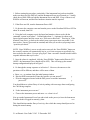
5. The Step-by-Step Phoenix Operation Guide................................................................ 13
5.1 New Feature – countdown clock............................................................................ 13
5.2 Setting up the detector and the mechanisms .......................................................... 13
5.3 Locating and marking the position of the slit ........................................................ 15
5.4 Fine Tuning the Grating Position........................................................................... 17
5.5 Observing .............................................................................................................. 18
5.5.1 Observing infrared bright, visually very faint objects .................................... 19
5.5.2 Integration time and data quality .................................................................... 20
5.6 Flats and darks ....................................................................................................... 21
5.7 Hollow cathode lamp ............................................................................................. 22
5.8 End of night............................................................................................................ 22
5.9 Saving your data .................................................................................................... 22
6. Operation Guide ........................................................................................................... 23
6.1 Temperature Calibration ........................................................................................ 23
6.2 Operating Temperatures.......................................................................................... 24
6.3 Typical Images ....................................................................................................... 25
7. Mechanism Information ............................................................................................... 27
2.1-m Phoenix User Guide V2.03 13 December 2013
2
Phoenix User Guide for the Kitt Peak 2.1-m
Telescope
1. General Description
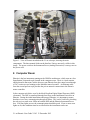
Phoenix is installed on the 2.1-m in a fixed orientation with the slit E-W because size and
weight restrictions require that the normal rotator and guider be removed. The instrument
itself is mounted to the Interface Unit, which is bolted directly to the back of the
telescope. The Interface Unit provides the proper back spacing for the f/15 telescope
focus to the instrument and also contains the calibration sources.
There are two electronics boxes on Phoenix, the Instrument Power on the west side of the
instrument (facing the control room) and the motor controller box on the SE side of the
instrument. There are two AC power lines which connect to the UPS power outlets on
the telescope, a set of four optical fibers from the Instrument Power to a fiber interface
box on the telescope, and an Ethernet cable running from the motor controller box across
the floor to the control room and thence to the computer room; this provides motor
control through a private network.
•
•
When moving the platform, one should be careful not to snag either the private
network Ethernet cable or the large air hose which removes heat from the
Instrument Power.
The power switch for the Instrument Power is a toggle switch on the top of the
electronics box. This should be the only control (other than the mechanical slides
on the Interface Unit) which the observer may have to operate.
The Interface Unit has three mechanisms which must be manually operated by the
observer.
•
•
•
The top slider controls an environmental cover which should be moved in during
the daytime to protect the instrument window and out while observing at night.
Calibrations may be done with the cover in.
The middle slider moves a mirror directing the light from the tungsten flat field
lamp into the instrument. The mirror should be out of the way when observing.
The bottom slider has three positions
o In – moves a ThAr emission line source into the beam
o Middle – open, used while observing
o Out – moves a CO gas absorption cell into the beam
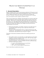
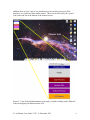
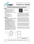
Figure 1 shows Phoenix installed on the telescope.
2.1-m Phoenix User Guide V2.03 13 December 2013
3
Figure 1: View of Phoenix installed on the 2.1-m telescope, showing the main
components. The three manual slides on the Interface Unit are not easily visible in this
image. The power switch to the Instrument Power (Analog Electronics) is on top, next to
the power cord.
2. Computer Room
Phoenix is the last instrument running on the WildFire architecture, which runs on a Sun
SparcStation 20 (named royal) located in the computer room. There is a local monitor
and keyboard in that room, but the observer runs Phoenix from the control room through
a VNC session to royal running on the MacMini named second-2. An Ethernet cable
from the second port on royal provides the private network connection to the Phoenix
motor controller.
In the computer rack below royal is the black Heurikon Digital Signal Processor (DSP)
electronics. The DSP is connected through four fibers to the Instrument Power box on
Phoenix. During the initial installation and setup of Phoenix, it is important to ensure
that there is two-way communication through all fibers. This can be verified by checking
the red receiver status error LEDs on both the DSP and the Phoenix Instrument Power
box. If all four lights are out, the communications should be good. If one or more error
lights are lit, this condition must be rectified before the instrument can be run.
2.1-m Phoenix User Guide V2.03 13 December 2013
4
During a normal nightly startup, when the instrument has been running, the observer
should not have to interact with any of the electronics on the instrument or in the
computer room. When the instrument is first installed or if it suffered a software crash
while observing, a more comprehensive startup procedure will be required. This manual
will cover these two situations in separate sections.
3. Normal Startup
3.1 WildFire Startup
When all is well during an observing run, the observer need only carry out a few tasks at
the end and beginning of the night. See Section 3.2 for a summary. On the first night of
a run the instrument support person will take the observer through a startup of the
WildFire program, since this may be necessary if the system crashes or needs to be
restarted for other reasons.
The 2.1-m control room contains two MacMini computers with large flatscreen displays.
One of these, second-1, is located at the Operator’s station and is used for controlling the
telescope operation. The other, located at the Observer’s station, is called second-2 and
is used for operating the various instruments used on the 2.1-m. Because there is no
dedicated Observing Assistant at the 2.1-m (except to give instruction on the first night of
a run), we recommend that two observers be present to operate both the telescope and the
instrument.
NOTE: In theory, a solo observer could operate both the telescope and instrument from
second-1 (but not from second-2) using different “spaces” for each task, but this has the
potential for confusion and some risk, since one of the tasks will be hidden when the
other is active.
NOTE: The instructions in this section assume that a previous session of WildFire has
been shut down gracefully and not as a result of a serious software crash, power
interruption to the Instrument Power or Digital Processors, or loss of communication over
the fiber network. These situations call for a more comprehensive recovery which will be
described in Section 4.
3.1.1 WildFire
WildFire is a command-line control system based on transputer technology, which was
thought in the late 1980s to be the Next Great Design in computing. This technology
combines integrated memory and serial communications and can run at Kitt Peak only on
the Sun Workstations which have been superseded by newer generations of
instrumentation control. Fortunately, it has been possible to incorporate some technology
advances into the Observer Interface, such as running WildFire through a VNC session
on the MacMinis with their dual monitors and incorporating GUIs to hide some of the
startup details from the user.
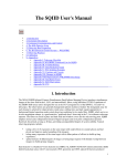
Figure 2 shows the left-hand monitor of second-2 from which one initiates the WildFire
startup. Any of the windows can be moved seamlessly from one monitor to the other. In
2.1-m Phoenix User Guide V2.03 13 December 2013
5
addition, there are four “spaces” on which one may run ancillary processes (Web
interfaces, etc.) and keep clutter under control. These may be selected by the “spaces”
icon on the task line at the bottom of the monitor screen.
Figure 2: View of the left-hand monitor of second-2. Double-clicking on the “Phoenix”
icon has brought up the Phoenix Menu GUI.
2.1-m Phoenix User Guide V2.03 13 December 2013
6
1. Starting with second-2 logged in as “2meter”, locate the “Phoenix” icon on the upper
left of the screen and double-click to open. This will bring up the Phoenix Menu, which
consists of four selections:
• Start Phoenix – this opens a VNC session to royal and brings up the initial startup
screens which allow for a full startup of WildFire.
• Restart IRAF – this will restart the IRAF session which normally comes up with
the Start Wildfire without exiting from WildFire (in case the xgterm or ds9 has
been inadvertently closed).
• Restart Phoenix – this will restart the Phoenix WildFire session if it has been
terminated gracefully and not as a result of a power or communications failure.
• Kill Phoenix – this will exit WildFire in a graceful manner and shutdown any
background processes. In theory, this should allow an efficient restart using the
Restart Phoenix button.
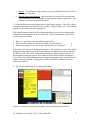
2. Click on the “Start Wildfire” button. This will bring up four windows, as shown in
Fig. 3. (Note: these windows have been resized and arranged to fit onto a single screen
on the second-2 monitor for clarity).
Figure 3: Second-2 monitor after commanding the Start Wildfire from the Menu GUI
•
•
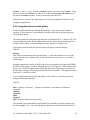
Phoenix IRAF – this is an IRAF xgterm running on royal and can be used for
accessing and quick-look examination of the data.
SAOimage ds9 – this is actually running on second-2, but will display images
from royal over a network once initialized.
2.1-m Phoenix User Guide V2.03 13 December 2013
7
•
•
Phoenix – this distinctive yellow window is the command line interface for all of
the Phoenix commands.
Phoenix Engineering Daemon – this red window can be used for executing lowlevel commands in the event that the system required extensive diagnostics. This
window is not for use by general observers.
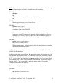
3. Follow the directions on the startup menu in the Phoenix window. You will be asked
a number of questions which must be read carefully. Simply hitting a <cr> will return the
default answer, which may not be appropriate.
This example assumes that the DSP and Instrument Power have not been interrupted or
communications through the fibers have been lost. These more dramatic cases will be
covered in the next section.
a. Enter <cr> to continue from the initial startup window
b. “Has the DSP been turned off since the last time you ran startwf?
c. “Has the instrument power been off since the last time you ran startwf?
n
n
At this point, the system will bootstrap the network. You should see a series of ten nodes
being bootstrapped; these are the fiber optic transceivers and network connections from
the DSP to royal. The system will then download four WildFire programs specific to
running Phoenix and open up two more windows labeled Phoenix Status and Phoenix
Saver, which will display the instrument mechanism/temperature status and the file saver
updates as images are taken. The program will then ask if these windows have been
initialized (Figure 4):
d. “Do you see engineering, saver, and status windows”
y
Figure 4: Second-2 monitor after opening the Saver and Status (blue) windows.
2.1-m Phoenix User Guide V2.03 13 December 2013
8
If the answer to the question is “y”, the program will go through an internal initialization,
then download five voltages. It will then return a final question:
e. “Do you want to activate the array?” Normally, you will answer “y” if planning to
observe. Do not answer ‘y’ unless the instrument and detector are cold.
The program will then query the location of the mechanisms, open up a second Phoenix
Daemon window and end with the message “Initialization complete” and the WildFire
“%” prompt.
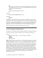
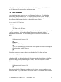
The end result is shown in Figure 5.
NOTE: Error messages (shown in Fig. 5) referring to the xterm are normal, vestiges of
the earlier use of xterm windows for running WildFire. The final error message about
expecting a Boolean value but getting “” refers to a dark slide mechanism which was
used on the Gemini South telescope but is not used at Kitt Peak.
At this point, you may wish to redistribute the windows among the two monitors to
reduce clutter. You should now be ready to set up the mechanisms and parameters for
observing, as described in the step-by-step operations section of this manual (Section 5).
One may also iconify the phxDaemon windows, as they are used only for diagnostic or
low-level commands.
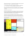
Figure 5: Second-2 monitor after a successful WildFire startup. The various steps are
annotated on the yellow WildFire command line window.
2.1-m Phoenix User Guide V2.03 13 December 2013
9
3.2 Nightly Startup and Shutdown (Summary)
Here we summarize the nightly startup and shutdown. See section 5 for the detailed stepby-step version.
During the course of a normal observing run, the instrument and all of the control screens
may be left running during the day. At the end of each night, the observer should only
need to:
• Deactivate the array by entering deactivate
• Close the dark slide (top slider on the Interface Unit)
Upon starting up the following evening, the observer must:
• Open the dark slide on the Interface Unit
• Activate the array by entering activate; enter a bias value near 0.320 to give 0.300
• Create a new data directory for the night on /data1/2meter in terminal
• Execute ped in Wildfire to enter the new data directory into WildFire code
• After the telescope has been started up, enter tcpon to establish communications
with the telescope
These instructions and the commands are described in more detail in the Step-by-step
Operations section of the Manual (Section 5).
NOTE: At the end of a Phoenix observing block, before the instrument is powered
off, the viewer should be moved to the ‘dark’ position and the filter, CVF, and slit
wheels to the ‘open’ position to protect the detector and filters from condensation
(see Section 5).
4. Startup in Special Circumstances
Because of the complex organization between the Sun computer royal, the DSP, and the
Instrument Power, it is necessary to establish communications between these in the
proper order. Once this has been done, restarting WildFire is fairly straightforward, as
described in Section 3. However, there are situations in which the simple startup will not
work, such as:
•
•
•
•
The computer software has crashed for some reason. If this happens, first try
using the “Kill Phoenix” button on the Phoenix menu to close all of the processes,
then “Start Phoenix” as described above. Depending on the cause and severity of
the crash, this might work.
There has been a significant power failure which affected the Instrument Power,
DSP, or royal, or any of them has been turned off for any reason.
Communication through the fibers has been lost for some reason. If this is
suspected, check the red Error LEDs on both the DSP and the Instrument Power.
If any of them is red, there is a hardware communication problem which must be
repaired before attempting to run WildFire.
The instrument has just been installed on the telescope, since the Instrument
Power will have been powered off.
2.1-m Phoenix User Guide V2.03 13 December 2013
10
1. Before starting the procedure, particularly if the instrument has just been installed,
make sure that royal, the DSP box, and the Instrument Power are all turned on. Visually
check the red fiber LEDs on both the Instrument Power and DSP. If any of them is red,
WildFire will not run, and the fiber hardware situation must be repaired.
2. If the fibers are OK, turn the Instrument Power OFF.
3. Go down to the computer room and turn the power on the Heurikon DSP box OFF for
about 30 seconds, then ON.
4. Using the local (computer room) keyboard and monitor, reboot royal with the
command “system royal reboot”. It should take about 3 – 4 minutes to reboot royal.
Ignore login requests until the screen says “Welcome to Kitt Peak”. Then log in. If the
terminal is not active, go back to the control room, open up an xterm on second-2, ssh
into royal as ‘2meter’ (password on terminal) and when you see the royal prompt, enter
“system royal reboot”.
NOTE: Since WildFire is run as an ssh session on royal, the “Start Wildfire” button on
the second-2 monitor will automatically log in, so it is not necessary to specifically log
into royal after the reboot. Execute “ping royal” from a second-2 terminal window until a
response indicates that royal is alive.
5. Once the reboot is completed, click the “Start Wildfire” button on the Phoenix GUI
(NOTE: the Instrument Power should still be OFF). This will bring up the normal
startup configuration displayed in Figure 3.
6. Go through the startup sequence as in Section 3. However, the answers to the
questions will be different, and there will be more of them.
a. Enter <cr> to continue from the initial startup window
b. “Has the DSP been turned off since the last time you ran startwf?”
c. “Was the computer rebooted with the DSP power on and the instrument
power off?”
y
y
You should then see a short flurry of activity ending with a message about configuring
the C004 being complete.
d. “Is the instrument power on now”
e. “Turn on the instrument power and enter <cr> when it is on”
n
Now go out the Instrument Power box and switch on the power (or have the Instrument
Scientist do this if logged in remotely), then:
<cr>
This should initiate another flurry of activity, after which the startup should proceed as
during the normal startup.
2.1-m Phoenix User Guide V2.03 13 December 2013
11
At this point, the system will bootstrap the network. You should see a series of ten nodes
being bootstrapped; these are the fiber optic transceivers and network connections from
the DSP to royal. The system will then download four WildFire programs specific to
running Phoenix and open up two more windows labeled Phoenix Status and Phoenix
Saver, which will display the instrument mechanism/temperature status and the file saver
updates as images are taken. The program will then ask if these windows have been
initialized (Figure 4).
f. “Do you see engineering, saver and status windows?”
If the answer to the question is “y”, the program will go through an internal initialization,
then download five voltages. It will then return a final question:
h. “Do you want to activate the array?” Normally, you will answer “y” if planning to
observe. Do not answer “y” unless the instrument and detector are cold.
The program will then query the location of the mechanisms and end with the message
“Initialization complete” and the WildFire “%” prompt.
The end result is shown in Figure 5.
2.1-m Phoenix User Guide V2.03 13 December 2013
12
5. The Step-by-Step Phoenix Operation Guide
5.1 New Feature – countdown clock
Throughout the history of IR array operation with WildFire, an annoying aspect of the
operating system was that the software architecture did not permit any estimate of the
time remaining in an exposure. The microcode would send out an initial read command
and wait for the data to come back when the exposure was completed. Although this is
still the case, it has been possible to program a countdown clock on second-2 which is
initiated by the start of an integration and gives the approximate time until the end of the
exposure. While not precise, it should be a very useful guide to the observer.
5.2 Setting up the detector and the mechanisms
In Wildfire window (Note that the Wildfire window is the same as the yellow Phoenix
window):
activate
Turns on the array. Start with the default bias value of 0.320. The echoed back
bias should then be 0.300. If it is not, then use
setbias {value}
Normally {value} should be 0.320 in order to get an echoed back bias of 0.300.
Adjust up and down to get to a read back of 0.300.
In a terminal window:
ssh to lapis
Check that you are in data directory (should be tmp_mnt/lapis/data1/2meter)
df
Check that there is sufficient disk space on lapis/data1 to store your data. Each
image is 1.05 MB in size.
In IRAF window:
mkdir {label}
For {label} use a directory name using the date, for example 2012nov23.
cd {label}
pwd
In Wildfire window:
ped
Stands for Parameter EDitor. You should leave most parameters as default.
However, you will want to change the header and pixel directory to match the
IRAF data directory. If the IRAF directory was, for instance
/lapis/data1/2meter/2012nov23, you should type in /data1/2meter/2012nov23 in
Wildfire.
eask
2.1-m Phoenix User Guide V2.03 13 December 2013
13
This sets the parameters whose values will be requested before each observation.
Set with “la” the parameters to be shown/requested by ask. Other parameters get
“l”, and will not be shown or requested before an observation. You can always
rerun eask if you change your mind. Note that while “picture number” is
automatically incremented by the software, you may want to set this to “la” so
that you see the frame number before beginning an observation, and can mark this
on your observing log.
ask
To get started make sure the integration time is set to a small value, pictures to 1,
lnrs to 1, coadds to 1.
The following commands involve mechanisms.
status s displays the current position of all of the instrument mechanisms in the
status window. The status display automatically updates when you move
mechanisms.
help {mechanism name} tells about the command and the position options.
IMPORTANT – make sure the mechanism command has finished; i.e., that you
get a prompt back, before typing anything else. This is the main cause of lost
time with Phoenix. If you type in a new command before the previous one
finishes you can hang the computer.
IMPORTANT – at the beginning of a run, the instrument scientist will initialize
the mechanisms (except for the collimator focus), which have home switches to
define the zero position using the command init <mechanism>. This command
may be done by the user if for some reason one of the mechanisms seems to have
become lost. However, the order of the words is important! For some reason, the
software interprets the word “init” as a position, so reversing the order of the two
words will attempt to move the mechanism to a position which is impossible for
some of the mechanisms.
Make sure the mechanism went where you wanted. The new position is echoed
back.
filt {pos value} – selects the filter. There is a second set of filters in the cvf
wheel, which is now effectively a second filter wheel. To use these first do filt
open and then cvf {pos value}. Otherwise, set cvf to open.
lyot {pos value} – sets the lyot stop for the telescope and wavelength
slit {pos value} – sets the slit. The commonly used 4 pixel slit is number 8.
viewer {pos value} The viewer positions are “open”, “dark”, or “image”.
Typically you will want “image” to start, if you will start by finding the slit
location. The choice for spectroscopy is “open”. (Note that for the viewer,
unlike for the other mechanisms, you cannot type “viewer 1” or “viewer 2”, etc.
You must use “viewer image”, “viewer open” or “viewer dark”.)
2.1-m Phoenix User Guide V2.03 13 December 2013
14
grat {pos in cm-1} K {offset} The grat K command moves the grating to a
given frequency. The offset parameter is necessary to account for the encoder
zero point. An offset of 800 works well as of May 2013.
grat {encoder position} – moves the grating to a given encoder position
If a mechanism fails to move, then try
kick {mech. Name} {pos value} -- this commands applies extra torque
When the telescope is running
tcpon
This starts communication between the telescope and the Phoenix computer. It is
sometimes needed at the start of the night. It should not be necessary after that.
5.3 Locating and marking the position of the slit
1. Acquire a V ~ 9 SAO star that is close to overhead. If you are observing in the 4-5
micron region use a bright star.
In Wildfire:
Check that the viewer is set to “image”
ask
Enter the title = target name, filename and the exposure time. Filename is just the
start of the filename, for example, “image” or “setup” for imaging the slit, or
“data” if you want all files to have the same file start. A 3-digit extension will be
appended to the end of this filename. Typically the exposure time should be
about 10 sec.
go
This takes an image of the sky through the slit.
NOTE: Initially, images may not display automatically on the ds9. If this is the case,
change to the current data directory in the IRAF window and display an image using the
IRAF “display” command: display <imagename> 1. If the image displays properly on
the ds9, succeeding images should autodisplay as they are taken.
In IRAF:
Measure position of the middle of the slit and write down the coordinates. If all
is well this should be close to x=128 and y= 510. This position will be different
for each filter. Mark down this position (xcenter, ycenter), and then
In Wildfire:
zcenter {xcenter}{ycenter} 90. 0.23
This will orient the software for the slit geometry. <xcenter> and <ycenter> are
the slit center coordinates measured above. 90 is the orientation of the slit on the
2.1-m (E-W) and 0.23 is the scale in arcsec per pixel at the 2.1-m.
2.1-m Phoenix User Guide V2.03 13 December 2013
15
NOTE: You must run zcenter prior to running either recenter, abba or ab for the first
time, since these routines require the coordinate and scale information.
In Wildfire:
slit open
ask
Set the time for an image of the star, typically about 1 sec.
go
In IRAF:
Measure position (xpos,ypos) of center of star.
In Wildfire:
recenter {xpos} {ypos}
This will move the telescope so that the star is at the (xcenter, ycenter)
coordinates of the center of the slit.
If you encounter any trouble with these routines, you can always do the
recentering yourself. Compare your measured position to that of the slit center,
multiply by 0.23 arcsec per pixel (at the 2.1-m), and move the telescope by the
right amount to center the star at the slit center using the commands below.
In Wildfire:
north {arcsec} or south {arcsec}
east {arcsec} or west {arcsec}
go
go takes another image. Make sure star is at the slit center location or iterate the
adjustments until the star is there.
On TV guider monitor, mark position of center with wax pencil. NOTE -- Each filter
will have a different position.
On the first night of an observing block, the instrument scientist will focus the star on the
array and then adjust the focus of the TV so the image is in focus. Afterwards, it should
only be necessary to adjust the secondary focus to maintain a sharply focused image on
the TV. If you wish to check the focus, use imexam and the ‘r’ key to generate a radial
plot of the star image. Iterate, using small (0.02) focus motions, until the best image is
obtained. NOTE: The focus readout is on the top module of the f/15 secondary
electronics rack, not the VDU display.
2. Acquire a relatively bright K giant or A star, move to marked spot on TV
In Wildfire:
slit {number of your science slit}
viewer open
2.1-m Phoenix User Guide V2.03 13 December 2013
16
ask
Enter name of source, set time to some small amount appropriate for the spectrum
of this bright star (use ITC). If star is very bright, multiple coadds can be used to
average several very short exposures.
east 10
This moves the star to the bottom of the slit.
go
In IRAF:
Measure signal using imexam and the ‘j’ key.
In Wildfire:
north 0.5
go
Then measure signal, repeat these steps moving the star small amounts north and south
(perpendicular to the slit) and recording signal. When you find the best signal move back
to this position, confirm reading, and mark on TV screen. Then move west 20 and repeat
the process. When done move east 10 and re-mark point at the middle of the slit. The
middle point is just used for acquisition so there is no need to peak up the signal here.
NOTE: Remember, the slit position will be different for each filter.
5.4 Fine Tuning the Grating Position
Using the best pair of bright star spectra obtained during the above peaking procedure (or
by observing a new pair of spectra) with the star at the east and west ends of the slit.
In IRAF:
imar {east spectral image} – {west spectral image} {diff image}
twodspec
apextract
apall {diff image}
Apall is the IRAF spectral extraction task. It will begin by asking a number of questions
about finding apertures. Answer “yes” to all, “1” to number of apertures to extract. You
will then get a display of a row cut across the image, showing the negative and positive
spectral sections. There should be an aperture marked on the peak of the positive feature.
If the centering is good, enter “q” and “yes” to the questions about tracing and fitting the
apertures. The display will show a plot of the fit to the spectral aperture sampled at
intervals (typically 10 pixels) along the spectrum. If the fit looks good, enter “q” again
and answer “yes” to the questions about storing the apertures and extracting the spectra.
You will finally get a spectral plot; answer “y” to the question about saving the spectrum.
The result will be a spectrum named “diffimage.0001.fits” (or “diffimage.ms.fits”) in the
data directory. The command “help apall” will bring up a more comprehensive
explanation for the task.
2.1-m Phoenix User Guide V2.03 13 December 2013
17
Display the spectrum using splot {diffimage.0001}.
Compare the spectrum to the Arcturus Atlas and figure out the central wavenumber.
Frequency increases with pixel number, so the orientation of the spectrum should be the
same on the display as in the Arcturus Atlas. Note how many wavenumbers off the
desired center the spectrum is. Add the opposite of this difference to your original
wavenumber and rerun grat with the corrected value. Reobserve the spectrum and
repeat the above analysis to converge on the desired central wavenumber.
During the November 2012 observing run, we found it necessary to adjust the
wavenumber setting in grat by -2 cm-1 in the K band.
5.5 Observing
It would be best to start with a bright star, perhaps a hot star for removing the telluric
lines. Observing a bright star, with a short integration time, minimizes time lost if
anything is not set up correctly.
NOTE: The array will saturate at approximately 9000 ADU. For the minimum
integration time of 1.002 sec, the saturation occurs at about 5000 ADU. We
recommend keeping the maximum signals to no more than half of these values to
avoid nonlinearity effects.
In Wildfire:
At the start of the night after the telescope has gone to the first star it might be necessary
to type:
tcpon
This starts communication between the telescope and the Phoenix computer.
tcpon should only be needed when the telescope is started.
For the first observation only the position angle and plate scale must be entered:
zcenter {xcenter} {ycenter} 90 0.23
<xcenter> and <ycenter> are the X and Y values of the slit image center on the
detector which were measured in the last section. These numbers will be close to
128 and 510, but will differ slightly for each filter. 90 is the position angle which
is always E-W on the 2.1-m. 0.230 is the 2.1-m plate scale in imaging mode.
For all observations:
ask
this command sets up the observing parameters for this observation. eask
determines which parameters are set by ask.
abba 20 {number of repeats}
20 is the nod (A-B separation) in arcseconds. This corresponds to the east 10 and
west 10 that were used above. This is a good value for the 2.1-m. abba will take
four spectra. The default number of repeats for the abba script is 1.
2.1-m Phoenix User Guide V2.03 13 December 2013
18
The command ab {nod} {number of repeats} is similar to abba, except that it just does
one observation at each point.
5.5.1 Observing infrared bright, visually very faint objects
If objects can not be seen on the guide TV they must be acquired in the IR using the
imaging mode. Tracking on the slit can be done using an offset star and the guide camera
(provided one is visible in the field).
In the near-IR:
In Wildfire:
viewer image
slit {your science slit}
ask
go
This images the slit. Record the mid point. This needs to be done once.
slit open
ask
If the exposure time is very short coadds =10 will average over 10 exposures.
go
east 10
go
west 10
In IRAF:
imar {image1} – {image2} {some name for the difference image}
displ {name of difference image} 1 This displays the difference in the ds9 window.
Measure the position of the positive star image.
In the thermal IR:
The sky will likely saturate the images. Use the neutral density filter in the cvf wheel to
reduce the flux. This filter is not intended to be used in spectroscopy mode so make sure
it is removed prior to science observing.
For both near-IR and thermal IR:
In Wildfire:
2.1-m Phoenix User Guide V2.03 13 December 2013
19
recenter {x pos} {y pos} Note that recenter requires a previous use of zcenter. If you
have not yet executed zcenter you must do so before using recenter. Recenter moves
the star to the zcenter position. It may be necessary to do this twice.
When the star is centered up a final image can be taken by putting the slit back in and
imaging through the slit.
5.5.2 Integration time and data quality
The data quality will naturally depend on conditions. Each observation should be
checked. It is the observer’s responsibility to do this and to talk to the start up person
about the data quality.
The starting point for setting the integration time is the Phoenix ITC. Using the ITC tool,
compute integration times for the planned observations. Most observations require four
separate frames (abba) so the total integration time should be divided by four.
After taking an observation the spectral image will appear on the ds9 display.
In IRAF:
imexam
This allows measurements of the spectral image, ‘j’ takes a horizontal cross cut of the
image and carries out a Gaussian fit; ‘k’ does the same in a vertical cut; ‘e’ provides a
contour map.
Roughly integrate the number of ADU in the cross cut using the peak signal and FWHM
provided on the graphics terminal. Multiply this by 9.2 (the gain in e/ADU) and take the
square root. This is the approximate S/N in this observation (ignoring the read noise of
the detector). Multiply by two to get the final S/N for four frames. The integration times
from the ITC can then be scaled.
A more detailed assessment of the data quality can be made by extracting a spectrum
using the following commands.
In IRAF:
imar {aperture a spectrum} – {aperture b spectrum} {some name for difference
spectrum}
twodspec
apextract
apall
onedspec
splot {name for difference spectrum.ms}
The spectrum can be smoothed if required and S/N measured on specific regions using
the tools in splot. The ‘s’ key will smooth the spectrum to a desired pixel resolution; ‘a’
2.1-m Phoenix User Guide V2.03 13 December 2013
20
will redefine the display window; ‘c’ will reset to the full display, and ‘m’ will calculate
the S/N between two cursor positions on the spectrum.
5.6 Flats and darks
Every time the grating is moved a new set of flats must be observed. To do this the
sliders on the interface unit are used. The sliders must be moved by hand. Pull the
mirror (middle mechanism) into the beam. The dark slide (top) can be open or closed.
The reference slide (bottom) should be at the middle (open) position.
For the near-IR (1-2.5 microns)
In Wildfire:
flamp on
This turns on the flat lamp.
Lamp flats require roughly 4 second exposures in the K band. We recommend using ask
to set up a test image. Execute this with go. Then measure the signal with the ‘l’
command in IRAF imexam. The maximum signal level should be between 1000 and
2000.
ask
Set the number of pictures to 10.
go
flamp off
This turns off the lamp.
ask
Type in a comment saying these are dark. The exposure time must be unchanged
from those taken with the lamp on.
go
When done remember to remove the mirror in the Interface Unit from the beam.
For the thermal IR (3-5 microns)
In the thermal IR, the ambient background is brighter than the flat field lamp, so the flat
exposures can be taken without turning on the lamp. Take a test exposure to set the
exposure time. Then as above
ask
Set the number of pictures to 10.
go
There are two schools of thoughts about darks at 4.6 microns, they are worthless or you
should take them. If you want darks it is necessary to move a mechanism within Phoenix
2.1-m Phoenix User Guide V2.03 13 December 2013
21
to the dark position. Then take 10 exposures with the same integration time as for the
flat.
When done remember to remove the mirror in the Interface Unit from the beam.
5.7 Hollow cathode lamp
The hollow cathode lamp works only in the 1-3 micron region. Using the bottom slider
on the Interface Unit, move the hollow cathode lamp into the beam (slider in).
In Wildfire:
hlamp on
ask
Generally it will take a minute or more to see hollow cathode lines.
go
hamp off
IMPORTANT – you must turn the lamp off after taking data. It has a limited lifetime
and is impossibly difficult to change.
When done remove the hollow cathode lamp from the beam (slider to middle position).
5.8 End of night
At the Interface Unit move the dark slide into place (top slider in).
In Wildfire:
deactivate
NOTE: At the end of a Phoenix observing block, before the instrument is powered
off, the viewer should be moved to the ‘dark’ position to protect the detector from
condensation with the command ‘viewer dark’. Also move the filter, CVF, and slit
wheels to the ‘open’ position.
5.9 Saving your data
While at Kitt Peak scp can be used to copy your data to your laptop. It is highly
recommended that you copy your data to your laptop and take the data away with you.
From your laptop: scp –rp 2meter@royal:{data directory} .
You can get the data directory using pwd in the IRAF window. Note that /tmp_mnt/lapis
should not be included; i.e., the directory should look like /data1/2meter/2012nov23
All data also goes into the Kitt Peak data archive.
2.1-m Phoenix User Guide V2.03 13 December 2013
22
6. Operation Guide
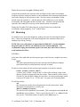
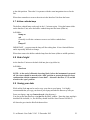
6.1 Temperature Calibration
The temperatures are measured as the forward bias voltage on a temperature-sensitive
diode operated at a current of 100 μa. Most of the diodes in Phoenix are 1N914 diodes,
which are relatively inexpensive; those on the detector and mount are factory-calibrated
Lakeshore diodes, which have a slightly different dependence from the 1N914. The
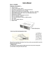
calibration curve for both diodes is presented in Figure 6. The status readbacks (Figure
7) are in voltages, so one may refer to this curve to convert to temperature.
In general, the 1N914 diodes read approximately 0.400 volts at room temperature and
1.000 volts at ~ 70K. The behavior in between is roughly linear with a slope of about 3
mv/K. Below 40 K (30K for the Lakeshore diode), the behavior becomes highly
nonlinear.
Figure 6: Calibration curves for the 1N914 and Lakeshore temperature diodes.
2.1-m Phoenix User Guide V2.03 13 December 2013
23
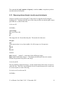
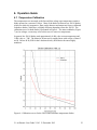
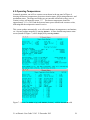
6.2 Operating Temperatures
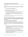
In normal operation, one will see a status screen shown in the top panel of Figure 6,
showing the detector temperatures, detector activation status, observation parameters, and
mechanism status. The lamps and sliders are not encoded at Kitt Peak as they were at
Gemini, so they will normally return “???” The detector temperature should be
approximately 1.11 v (28 K) and the detector heater power should read a nonzero value,
indicating that the temperature control is active.
This screen updates automatically, so it will record changes in temperatures, mechanisms,
etc. One may update manually by entering status s. A more detailed temperature status
screen (bottom of Figure 7) can be displayed by entering status t.
Figure 7: Screens for status s (top) and status t (bottom), with the instrument cold.
2.1-m Phoenix User Guide V2.03 13 December 2013
24
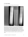
6.3 Typical Images
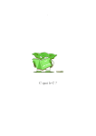
Figures 8 and 9 show some typical images under normal operation.
Figure 8 (from left): a. Dark frame. There are some noisy and/or high dark current
pixels in the image, which is normal. The crack in the lower left is an array defect. b.
Flat field image; the striped pattern in the upper half of the array is a normal property of
the detector/controller. c. A frame showing an unusual “Phobos” event. These are
believed to be electrical discharges within the array introduced by stresses and are more
frequent during the first few days after the instrument has been cooled. The dark current
in the lower 75% of the array is evident in this 900 s exposure is at a level ~ 350 e. Some
of this may result from very low level thermal background. d. Spectrum of the flat field
lamp at 4275 cm-1 with the CO cell in the beam. Only six of the low-J 2-0 lines are
visible.
2.1-m Phoenix User Guide V2.03 13 December 2013
25
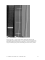
Figure 9 (from left): a. Image of ThAr hollow cathode lamp taken during the
spectrograph focus procedure (section 5.9). b. Raw image of a star in the 6395 cm-1
band; note the OH emission lines from the atmosphere. c. Result of subtracting two
images after dithering along the slit, demonstrating the removal of the sky features.
2.1-m Phoenix User Guide V2.03 13 December 2013
26
7. Mechanism Information
Of the seven mechanisms, five have discrete positions which can be commanded by
number or name (Section 5). The grating and focus mechanisms can be moved
continuously.
Filter: This wheel has 13 positions, including an open. The filter names are the
photometric band and the central frequency in cm-1 (e.g., K4220 is at 4220 cm-1).
CVF: This originally housed a continuously variable filter (CVF), but is now a second
filter wheel. The naming convention is the same as for the filter wheel. Note that one of
the Filter or CVF position must be open.
Slit: There are three slit widths: 2, 3, and 4 pixels. The 2 and 3 pixel slits have different
lenses for three wavelength regions to focus the pupil on the cold (Lyot) stop. The open
position is used for imaging the field.
Lyot: This wheel contains pupil stops for the 2.1-m and 4-m telescopes. Because the
Phoenix foreoptics are transmissive, the pupil will be imaged at slightly different axial
locations in the different wavelength regions, so there is a different Lyot stop for a
particular photometric band. The masks are used for setup only.
Viewer: This can be used to image the slit or object directly on the detector (image), for
darks (dark), or for normal spectroscopy (open). The Lyot position is used during setup.
Table 1 Phoenix Mechanism Positions
No.
1
2
3
4
5
6
7
8
9
10
11
12
13
14
15
16
Filter
open
M2150
J9232
L2734
K4220
K4308
L3290
K4484
M2030
J7799
K4798
H6420
J8265
CVF
open
ND
M1930
L3010
L2462
K4578
L2870
K4396
K4667
H5073
L3100
Slit
pinhole_n1
54μm_0.9-2.0
54μm_1.9-2.8
54μm_3.0-5.0
84μm_0.9-2.0
84μm_1.9-2.8
84μm_3.0-5.0
107μm_1.0-5.0
lyot_viewer
open
plus
dark
Lyot
dark
4m_1.1
4m_1.5
4m_2.5
4m_3.6
4m_5.1
2m_1.1
2m_1.5
2m_2.5
2m_3.6
2m_5.1
4m_mask_2.5mag_1.5
4m_mask_2.5mag_3.0
2m_mask_2.5mag
mask_5mag
secondary_mask
2.1-m Phoenix User Guide V2.03 13 December 2013
Viewer
image
dark
open
lyot
27
Table 2 Phoenix Order Sorting Filters
Name
M1930
M2030
M2150
L2462
L2734
L2870
L3010
L3100
L3290
K4132
K4220
K4308
K4396
K4484
K4578
K4667
K4748
H6073
H6420
J7799
J8265
J9232
J9671
Filt
1
9
2
1
4
1
1
1
7
5
6
1
8
1
1
11
1
12
10
13
3
-
CVF
3
1
1
5
1
7
4
11
1
1
1
8
1
6
9
1
10
1
1
1
1
-
cm-1
1890-1970
1980-2030
2105-2190
2410-2495
2680-2770
2820-2910
2950-3050
3030-3145
3240-3355
4077-4156
4188-4263
4258-4355
4355-4446
4429-4525
4525-4630
4617-4717
4704-4803
6017-6129
6377-6464
7750-7865
8243-8360
9183-9286
9652-9709
µm
5.076-5.291
4.808-5.050
4.566-4.751
4.008-4.149
3.610-3.731
3.436-3.545
3.279-3.390
3.180-3.300
2.980-3.085
2.406-2.452
2.348-2.392
2.296-2.349
2.249-2.296
2.210-2.250
2.160-2.210
2.120-2.166
2.082-2.126
1.632-1.662
1.547-1.568
1.271-1.290
1.196-1.213
1.077-1.089
1.030-1.036
Encoder Order
-14764
11
7897
11
-5208
12
-13603
14
2131
15
-4716
16
-10368
17
2340
17
-22532
19
-4064
23
-13670
24
-4421
24
-13651
25
-4751
25
-12987
26
-4221
26
-13618
27
-6514
34
-7198
36
-9878
44
-13620
47
-9151
52
-13662
55
Range (cm-1)
1926.7-1934.3
2024.3-2035.7
2144.7-2155.4
2456.4-2467.6
2726.7-2741.3
2862.8-2877.2
3002.9-3017.1
3091.7-3108.3
3283.2-3296.8
4121.6-4142.4
4210.4-4229.6
4297.2-4318.8
4386.0-4406.0
4472.8-4495.2
4567.5-4588.5
4655.3-4678.7
4737.2-4758.7
6058.1-6087.9
6404.4-6435.6
7780.6-7817.4
8246.2-8283.7
9210.0-9254.0
9649.1-9692.9
NOTE: Filters K4132 and J9671 are not currently installed in Phoenix
Name: Filter name. Photometric band and approximate center frequency
Filt, CVF: The ‘filt’ and ‘cvf’ settings for the filter
cm-1 : The approximate FWHM of the filter in cm-1
µm : The approximate FWHM of the filter in microns
Encoder: The approximate ‘grat’ encoder setting of the center frequency with no offset
Order: The grating order at the center frequency
Range: The frequency coverage on the detector (in cm-1) at the center frequency setting
2.1-m Phoenix User Guide V2.03 13 December 2013
28