1
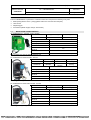
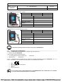
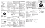
CHIERICI TITO s.r.l.
Via L. B. Alberti, 4 - 42048 Rubiera (RE)
CT – TRANSFER KIT
(220 V – 12 V)
OPERATING INSTRUCTIONS
Machine Directive 2006/42/CE
Rev 2 dated 19/01/2010
READ ALL THE INFORMATION CONTAINED IN THIS MANUAL BEFORE USING THE
MACHINE AND CAREFULLY FOLLOW THE INSTRUCTIONS.
PDF compression, OCR, web optimization using a watermarked evaluation copy of CVISION PDFCompressor
CHIERICI TITO s.r.l. - Via L. B. Alberti, 4 - 42048 Rubiera (RE)
Machine Directive
2006/42/CE
CT – TRANSFER KIT
Rev 2 dated
19/01/2010
OPERATING INSTRUCTIONS
Page 2 of 9
SUMMARY
1
1.1
1.2
1.3
DESCRIPTION CT – TRANSFER KIT...................................................................................................3
MODELS AND CHARACTERISTICS ................................................................................................................ 3
EC DIRECTIVES AND MARKING ..................................................................................................................... 4
INTENDED USE ................................................................................................................................................ 5
2
HANDLING AND TRANSPORT ............................................................................................................5
3
INSTALLATION .....................................................................................................................................5
3.1
3.2
3.3
4
4.1
4.2
PRELIMINARY CHECKS................................................................................................................................... 5
CONNECTING THE PIPES .............................................................................................................................. 5
ELECTRIC POWER PUMP USE....................................................................................................................... 5
MECHANICAL LITRE-COUNTER CT-80..............................................................................................6
OPERATION...................................................................................................................................................... 6
SPARE PARTS - MECHANICAL LITRE-COUNTER CT-80 .............................................................................. 7
5
AUTOMATIC GUN – OPERATION........................................................................................................8
6
MAINTENANCE .....................................................................................................................................8
6.1
6.2
6.3
6.4
7
7.1
ELECTROPUMP MAINTENANCE..................................................................................................................... 8
TROUBLESHOOTING - ELECTROPUMPS ...................................................................................................... 8
LITRE-COUNTER CT-80 MAINTENANCE........................................................................................................ 9
GUN MAINTENANCE........................................................................................................................................ 9
DISPOSAL .............................................................................................................................................9
DISPOSAL FOR THE ELECTRIC PUMP .......................................................................................................... 9
PDF compression, OCR, web optimization using a watermarked evaluation copy of CVISION PDFCompressor
CHIERICI TITO s.r.l. - Via L. B. Alberti, 4 - 42048 Rubiera (RE)
CT – TRANSFER KIT
Rev 2 dated
19/01/2010
OPERATING INSTRUCTIONS
Page 3 of 9
Machine Directive
2006/42/CE
1
DESCRIPTION CT – TRANSFER KIT
The CT-TRANSFER KIT is produced in 5 different models and comprises the following main parts:
⇒ Electropump (electric motor + pump) (please refer to the user manual in the pack)
⇒ Litre-counter
⇒ Dispensing gun
⇒ Accessories (diesel oil pipe, clamps, suction filter)
1.1
MODELS AND CHARACTERISTICS
CT-TRANSFER KIT - TURTLE - 220V - 60 l/min
Part no.
Type of Casing
Weight
Closed
17000 g
15.0500.26
Volt
220
Delivery
60 l/min
Electropump
PANTHER 56
Gun
Black rubber hose for
diesel oil
Suction filter
Automatic 60 l/min
4m
Brass with non-return valve
Accessories
Note: Supplied only with the 60/min automatic gun
CT-TRANSFER KIT 220V Movable - 60 l/min
Part no.
3 hose connections + 4 clamps
Type of Casing
Type of Gun
Weight
15.0500.01
Movable
15700 g
15.0500.05
Movable
PAL80 alum.
Automatic
60 l/min
220
Volt
Delivery
Electropump
Black rubber hose for
diesel oil
Suction filter
Accessories
16700 g
60 l/min
PANTHER 56
4m
Brass with non-return valve
3 hose connections + 4 clamps
Note: Supplied with guns: Gun PAL80 in aluminium - Automatic gun 60l/min
CT-TRANSFER KIT 220V Wall mounted - 60 l/min
Part no.
15.0500.04
Volt
Delivery
Type of Casing
Weight
Wall mounted
13700 g
220
60 l/min
Electropump
PANTHER 56
Gun
Black rubber hose for
diesel oil
Suction filter
PAL80 alum.
Accessories
Note: Supplied only with gun PAL80 in aluminium
4m
Brass with non-return valve
3 hose connections + 4 clamps
PDF compression, OCR, web optimization using a watermarked evaluation copy of CVISION PDFCompressor
CHIERICI TITO s.r.l. - Via L. B. Alberti, 4 - 42048 Rubiera (RE)
CT – TRANSFER KIT
Rev 2 dated
19/01/2010
OPERATING INSTRUCTIONS
Page 4 of 9
Machine Directive
2006/42/CE
CT-TRANSFER KIT 12V Movable - 40 l/min
Part no.
Type of Casing
Weight
Movable
12200 g
15.0550.01
Volt
12
Delivery
40 l/min
Electropump
BY PASS 2000
Gun
Black rubber hose for
diesel oil
Suction filter
PAL80 alum.
4m
Brass with non-return valve
Accessories
Note: Supplied only with gun PAL80 in aluminium
3 hose connections + 4 clamps
CT-TRANSFER KIT 12V Wall mounted - 40 l/min
Part no.
15.0550.02
Type of Casing
Weight
Wall mounted
10200 g
Volt
12
Delivery
40 l/min
Electropump
BY PASS 2000
Gun
Black rubber hose for
diesel oil
Suction filter
Accessories
Note: Supplied only with gun PAL80 in aluminium
PAL80 alum.
4m
Brass with non-return valve
3 hose connections + 4 clamps
Consult the operating instructions before using the CT-TRANSFER KIT
1.2
EC DIRECTIVES AND MARKING
The CT – TRANSFER KIT is manufactured in conformity with the provisions of:
⇒ Machine Directive 2006/42/CE ;
it also complies with the following directives:
⇒ Low Voltage Directive (220 V models only):
⇒ EMC Directive:
2006/95/CE
2004/108/CE
The CT – TRANSFER KIT is provided with "CE" marking in conformity with Machine Directive 2006/42/CE , par. 1.7.3
Annex 1 and Annex 3. The information and marks given on the dataplate are as follows.
•
•
•
•
•
Mark
Manufacturer's details and address
Type of machine
Serial no.
Year of construction
Do not tamper with or make modifications to CT-TRANSFER KIT. Such modifications can invalidate
the "CE" marking and the declaration of conformity.
PDF compression, OCR, web optimization using a watermarked evaluation copy of CVISION PDFCompressor
CHIERICI TITO s.r.l. - Via L. B. Alberti, 4 - 42048 Rubiera (RE)
Machine Directive
2006/42/CE
CT – TRANSFER KIT
Rev 2 dated
19/01/2010
OPERATING INSTRUCTIONS
Page 5 of 9
1.3
INTENDED USE
The CT-TRANSFER KIT is intended for transferring diesel oil, normally from a fixed container (cistern) to a movable one
(tank).
FLUIDS ALLOWED:
DIESEL OIL with VISCOSITY of 2 to 5.35 cSt (at temperature 37.8°C), with min. flash point (PM): 55°C
FLUIDS NOT ALLOWED:
RELATED RISKS
FLUIDS NOT ALLOWED
PETROL
FLAMMABLE LIQUIDS with min. flash
point PM < 55°C
FLUIDS WITH VISCOSITY > 20 cSt
MOTOR OVERLOAD
WATER
PUMP OXIDATION
LIQUID FOODS
THEIR CONTAMINATION
PUMP CORROSION
HARM TO PEOPLE
FIRE – EXPLOSION
DAMAGE TO THE GASKETS
CORROSIVE CHEMICAL PRODUCTS
SOLVENTS
2
FIRE – EXPLOSION
FIRE – EXPLOSION
HANDLING AND TRANSPORT
Given the limited weight and size of the pumps (par. 1.1) lifting equipment is not required for handling the CT
TRANSFER KIT. The KIT is carefully packed before shipment. Check the packing on receipt and store in a dry place.
3
INSTALLATION
3.1
PRELIMINARY CHECKS
Check that the KIT was not damaged during transport or storage.
Carefully clean the inlets and outlets, removing any dust or residual packing material.
Make sure the motor shaft turns freely.
Check that the electrical data matches that given on the dataplate.
Important! The motors are not the flameproof type. Do not install in places where flammable
vapours may be present.
3.2
CONNECTING THE PIPES
Before connecting, make sure the pipes and suction tank are free of scale or threading residuals which could damage
the pump and accessories. Before connecting the delivery pipe partly fill the pump chamber with diesel oil to facilitate
priming.
In case of connection pipes with taper thread, use an appropriate tightening force to avoid damaging the threaded
inlets/outlets of the pumps.
SUCTION PIPE
Recommended min. nominal diameters: ¾ ”
Recommended nominal pressure: 10 bar
Use pipes suitable for operation in negative pressure
DELIVERY PIPE
Recommended nominal diameters: ¾ ”
Recommended nominal pressure: 10 bar
IMPORTANT!
Only use pipes having suitable characteristics. The use of pipes unsuitable for diesel oil can cause
pollution as well as damage to the pump and people.
Loosening of the connections (threaded connections, flanges, gaskets) can cause serious safety
and ecological problems. Check all the connections after initial installation and then daily. Tighten
all the connections if necessary.
3.3
ELECTRIC POWER PUMP USE
before starting the electric power pump, please refer to the user manual in the pack.
PDF compression, OCR, web optimization using a watermarked evaluation copy of CVISION PDFCompressor
CHIERICI TITO s.r.l. - Via L. B. Alberti, 4 - 42048 Rubiera (RE)
Machine Directive
2006/42/CE
4
CT – TRANSFER KIT
Rev 2 dated
19/01/2010
OPERATING INSTRUCTIONS
Page 6 of 9
M ECHANICAL LITRE-COUNTER CT-80
4.1
OPERATION
The CT-80 is a mechanical litre-counter with wobble plate, designed for accurate measuring in transferring diesel oil and
other liquids compatible with the construction material.
TECHNICAL DATA
Mechanism
Wobble Plate
Delivery
From 20 to 80 (5+21 GpM) litres/min
Operating pressure
From 0.1 to 3.5 (1.45+50 psi) bar
Working temperature
-10 + 50 (+14 + 122'F) °C
Pressure loss (at 80 l/min diesel oil)
0.3 (4.3S psi) bar
Accuracy after setting
1%
Partial indicator
Max 999 (99.9 / 10 Gal.) litres
Totaliser indicator
Max 999999 (99999.9 / 10 Gal.) litres
Precision
0.1 (0.1 / 10 Gal.) litres
Connections
1”, (BSp/NpT)* %" (BSp/NpT)
Weight
1" 1.3S -3/4, 1.45 Kg
Packing dimens. (Vert. version)
210x141x146 mm
Packing dimens. (Horiz. version)
210x190x140 mm
USE
It can be used in gravitational systems and in circuits with electric or manual pumps equipped with bypass. Once
installed and set (if necessary), the litre-counter is ready for use. To zero-set the partial counter, turn the reset knob
clockwise. The totaliser indicator cannot be reset in any way. It is inadvisable to use the CI80 in areas where
temperatures higher than those recommended can occur due to their exposure to the sun. For correct operation of the
litre-counter its use together with a filter is recommended.
INSTALLATION
Built to work at maximum pressures of 3.5 bar (50 psi), it must be fitted so that it does not suck unfiltered liquids or air.
The flow of liquid to be transferred must follow the direction of the two arrows in relief on the back of the litre-counter. As
shown in figure 1, the inlet can be turned to the most suitable position, after undoing the 4 set screws (N' 20 exploded
view). Overpressures may be generated in the system; therefore it is
advisable to fit an overpressure valve set to 4 bar (57 psi) on the pump. In
case of systems working without pumps, i.e. gravitational, for correct
operation a height difference of at least 1 metre between the tank outlet and
the PAL80 or PMP80 type gun is necessary.
N.B. = To avoid damage and breakage in the plastic hexagonal body
containing the inlet and outlet unions, only use a CH44 SPANNER. (See
Figure opposite).
SETTING
The litre-counter is factory-set to a pressure of 1.5 Bar (21 PSI) transferring
diesel oil with a delivery of approx. 70l/min (18.49 GPM). As the operating
pressure is an important factor for the reading mechanism, setting must be
repeated when using different pressures and/or liquids. Resetting is
necessary every time the litre-counter is disassembled for maintenance or used for liquids different
from diesel oil.
SETTING PROCEDURE:
1. Unscrew the setting plug (plug A in fig. 2).
2. Stop the flow by closing the dispensing gun without stopping the pump.
3. Reset the partial indicator.
4. Dispense at a flowrate for obtaining the required accuracy, transferring
into a calibrated recipient of not less than 20 litres (5 Gallons) capacity.
Compare the value indicated by the partial totaliser with that of the recipient
(real value): turn the adjustment screw (N" 26 exploded view) clockwise if
lower and clockwise if higher.
5. Repeat operation 4 until the measurement is satisfactory.
6. Tighten the setting plug.
PDF compression, OCR, web optimization using a watermarked evaluation copy of CVISION PDFCompressor
CHIERICI TITO s.r.l. - Via L. B. Alberti, 4 - 42048 Rubiera (RE)
Machine Directive
2006/42/CE
4.2
CT – TRANSFER KIT
Rev 2 dated
19/01/2010
OPERATING INSTRUCTIONS
Page 7 of 9
SPARE PARTS - MECHANICAL LITRE-COUNTER CT-80
Always specify the spare part position no. with the product no.
PDF compression, OCR, web optimization using a watermarked evaluation copy of CVISION PDFCompressor
CHIERICI TITO s.r.l. - Via L. B. Alberti, 4 - 42048 Rubiera (RE)
CT – TRANSFER KIT
Rev 2 dated
19/01/2010
OPERATING INSTRUCTIONS
Page 8 of 9
Machine Directive
2006/42/CE
5
AUTOM ATIC GUN – OPERATION
MODELS
Mod. 2.0370.01
Model 2.0370.02
Automatic gun G60 l/min with 1”F
swivel union
Automatic gun F60 l/min 3/4” F inlet
INSTALLATION
This automatic gun is supplied ready for use.
It is necessary to apply a thin layer of sealant on the inlet union. It
is advisable to install a filter with filtering capacity of 50 MESH on
the system.
METHOD OF USE
The closing mechanism is activated when the fuel level covers the inside hole of the nozzle at the end of the gun. To
activate the closing mechanism a pressure of at least 0.5 bar is necessary and in any case not higher than 2 bar. This
gun can be used with all the electropumps available on the market.
TRANSFER MAX 60 L/MIN.
6
M AINTENANCE
6.1
ELECTROPUMP MAINTENANCE
The electropumps require minimum maintenance.
⇒ Every week, check that the pipe joints are not loose, to avoid possible leaks.
⇒ Check the pump body every month and keep it clean of any impurities.
⇒ Check the pump filter every month and keep it and any other filters installed clean.
⇒ Every month, check that the power supply cables and the plug socket are in good condition.
⇒ 12 V electropump: every month, check the presence of grease on the surfaces of contact between the cover and
terminal block body.
6.2
TROUBLESHOOTING - ELECTROPUMPS
Problems
The motor does not turn
The motor turns slowly in the
starting stage
Possible cause
No power
Rotor blocked
Motor trouble
Corrective action
Check the electrical connections and safety systems
Check for possible damage or obstructions to rotating parts
Wait until the motor has cooled, check restarting, look for the
cause of overtemperature
Contact the After-Sales Service
Low supply voltage
Bring the voltage within the required limits
Low level in suction tank
Foot valve blocked
Filter clogged
Fill the tank
Clean and/or replace the valve
Clean the filter
Lower the pump with respect to the tank level or increase the
section of pipes
Thermal protector tripped
Excessive negative suction pressure
Low or no delivery
High circuit pressure losses (operation with
bypass open)
Blocked bypass valve
Air entering the pump or suction pipe
Constriction in suction pipe
Low rotation speed
Pump very noisy
Leaks from pump body
The suction pipe rests on the bottom of the
tank
Presence of cavitation
Irregular operation of bypass
Air in the diesel oil
Damaged seal
Use shorter or larger diameter pipes
Dismantle the valve, clean and/or replace it
Check the seal of connections
Use a pipe suitable for working in negative pressure
Check the voltage at the pump, adjust the voltage and/or use
cables of larger section
Lift the pipe
Decrease the negative pressure in suction
Dispense until venting the air in the circuit
Check the suction connections
Check and if necessary replace the mechanical seal
PDF compression, OCR, web optimization using a watermarked evaluation copy of CVISION PDFCompressor
CHIERICI TITO s.r.l. - Via L. B. Alberti, 4 - 42048 Rubiera (RE)
Machine Directive
2006/42/CE
CT – TRANSFER KIT
Rev 2 dated
19/01/2010
OPERATING INSTRUCTIONS
Page 9 of 9
6.3
LITRE-COUNTER CT-80 MAINTENANCE
Correct installation and use make routine maintenance unnecessary.
Whenever filtering upstream of the litre-counter is insufficient, the measuring chamber may become clogged or worn, to
the detriment of accuracy. In case of this problem, disassemble the measuring chamber (to be carried out by a qualified
technician) after making sure that all the liquid has come out of the litre-counter and connected pipes. In case of
removal and opening of the litre-counter, when reassembling it make sure the cam of the bracket kit with gears and cam
(pos. 12) does not clash with the pin of the volumetric chamber unit (pos. 26).
After cleaning and possible replacement of parts, reset the litre-counter.
Litre-counter disassembly operations must be carried out after removing it from the system.
PROBLEMS CAUSES CURES
Incorrect setting
Unsatisfactory
Measuring chamber dirty/clogged
accuracy
Air in the fluid
Low delivery
Measuring chamber dirty/clogged
Filter clogged / dirty
Repeat setting
Clean the measuring chamber
Identify and eliminate leaks in suction lines
or add a foot valve
Clean the measuring chamber
Clean the filter
6.4
GUN MAINTENANCE
The gun does not require any maintenance.
It is advisable to periodically check the filter and if necessary clean it every 1000 liters transferred.
The possible causes of malfunction are mainly due to three factors:
⇒ Gun dirty in the hole inside the nozzle at the end of the gun.
⇒ Pressure below 0.5 bar in the liquid to be transferred (e.g. transfer of liquids by gravity).
⇒ Flowrate too high (max 60 l/min).
7
DISPOSAL
In case of demolition, entrust the various parts of the KIT to firms specialised in the disposal and recycling of industrial
waste.
Refer to the local regulations for their correct disposal.
The metal parts, also painted, can normally be recovered by specialised firms in the scrap metal sector.
Other parts, such as pipes, rubber seals and plastic parts should be entrusted to firms specialised in the specific
disposal sector.
7.1
DISPOSAL FOR THE ELECTRIC PUMP
the producer of the electric power pump "PIUSI" code reg. AEE IT 08020000000721
the producer complies with a collective system for disposal called "Consorzio REMEDIA" with information
which can be consulted on the web site: www.consorzioremedia.it .
In case of machine maintenance or demolition, do not disperse pollutant parts in the environment.
PDF compression, OCR, web optimization using a watermarked evaluation copy of CVISION PDFCompressor