1
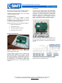
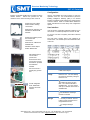
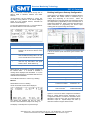
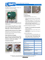
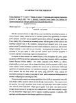
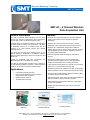
Structure Monitoring Technology SMT-A3 Datasheet SMT-A3 – 8 Channel Wireless Data Acquisition Unit General Description Features The SMT-A3 Wireless Data Acquisition unit is a multichannel high precision measurement device designed to interface with a variety of different building sensors. • Supports up to 8 external resistance channels capable of reading wide moisture content ranges and precision thermistors. The sleek design of the SMT-A3 allows it to be installed in occupied spaces in building units and homes. The SMTA3 seamlessly attaches to a double junction box and supports up to eight external sensors with optional integrated sensors. • Supports up to 8 0-5V sensors such as RH, pressure differential, LVDT, displacement, light sensors and more. The 24-bit A/D and long range wireless proven on the SMT-A2 platform is duplicated on the SMT-A3 making it ideal for building monitoring in both new construction and retrofit work. Options for integrated CO2, RH, temperature differential pressure are available upon request. and The SMT-A3 communicates wireless sensor readings to the SMT Building Intelligence gateway. Optional powered repeaters can be used to extend the wireless range. • Optional integrated relative humidity and temperature sensors. • Sensors are installed using a two part terminal block permitting sensor lengths to be cut to their appropriate lengths and terminated prior to installing electronics. • Large internal memory allows an 8 channel unit to log hourly data for up to 3 years without extracting data. • Wireless transceiver with 1000m line of sight communication. Optional repeaters can be used to extend the wireless range. Applications • • • • • • Supports up to 4 differential voltage inputs capable of reading sensors such as thermocouples, heat flux and more. Gain amplification boost circuitry is available to measure very small voltage differentials. Permanent monitoring solutions Remote sensor analysis and data collection High precision data acquisition Building science research Targeted repair monitoring • Communicates to SMT Building Intelligence Gateway (BiG) via USB to Wireless device; SMT-I2. • Extreme low power device and 3 AA battery pack makes the SMT-A3 suitable for long term battery operation. • USB connectivity supports data downloads, configuration and firmware upgrades. • Backlit LCD user interface for easy network and sensor verification à Data Acquisition (SMT-A3) à Gateway (BiG) with USB Interface (SMT-I2) Internet (Analytics) SMT Research Ltd. – 200-75 W Broadway, BC V5Y 1P1 – Tel: 204.480.8579 – Fax: 204.480.8579 Website: www.smtresearch.ca Email: [email protected] RS-1104 Rev 4 Page 2 Structure Monitoring Technology SMT-A3 Datasheet Electrical Performance Measurement Specifications Wireless Internal Temperature Specification IEEE 802.15.4 Working Frequency 2.4 GHz – 2.4835 GHz Power 20dBm (100mW) Output Range (free air) 1000m. Powered repeaters can be added to extend range. Max Nodes per coordinator 32 (dependent on application density and acquisition speed) Sensor Interchangeability Life 3 - 5 years (depending on sample rate) Resolution Accuracy Hysteresis Repeatability Type 3 AA Alkaline Battery Pack Battery Memory and USB Memory 16 Mbit EEPROM for data storage Stores 340,000 data points. USB USB 1.0 Interface Environmental Sensor Range Resolution Accuracy Cantherm MF58104F3950 Beta 4390K -40°C to +70°C 0.1°C ±1°C Internal Relative Humidity (optional) Honeywell HIH-4000-001 0-59% RH ±5% 60-100% RH ±8% 0.5% RH ±5% RH 3% RH ±0.5% RH Resistance Range Resolution Accuracy 10Ω to 100Ω 1Ω ±5% Range Resolution Accuracy 100Ω to 100KΩ 10Ω ±1% 100KΩ to 1GΩ 1KΩ ±5% Operating Temperature 0° to 40°C / 32° to 104°F Range Resolution Accuracy Storage Temperature -25° to 70°C / -13° to 158°F Voltage Humidity 5% to 100% RH non-condensing Electrostatic Discharge (ESD) 8kVdc air, 4 kVDC contact (exposed inputs) Range Resolution Accuracy Enclosure The enclosure is designed for indoor use only. Consult SMT for outdoor rated units. 0V to 5V 100mV ±5% Mechanical Standard Enclosure Dimensions Regulatory Regulatory Contains FCC ID: OA3MRF24J40MB This device complies with Part 15 of the FCC Rules. Operation is subject to the following two conditions: (1) this device may not cause harmful interference, and (2) this device must accept any interference received, including interference that may cause undesired operation. Contains IC: 7693A-24J40MB Specifications are subject to change without notice Weight Connections Resistance Ports 4 to 8 channels Resistance 100Ω to 1GΩ Voltage Ports 4 to 8 channels 5V, GND, Vin Or Differential voltage Interface LCD Network join/rejoin Display measurements Buttons Menu/Select buttons SMT Research Ltd. – 200-75 W Broadway, BC V5Y 1P1 – Tel: 204.480.8579 – Fax: 204.480.8579 Website: www.smtresearch.ca Email: [email protected] RS-1104 Rev 4 Page 3 Structure Monitoring Technology SMT-A3 Datasheet Input Port Connectivity 0-5V Sensors A3’s can be configured to have 8 resistance inputs, 8 voltage inputs or 4 resistance and 4 voltage inputs. 0-5V sensors such as RH sensors, differential pressure sensors and solar radiation sensors can be connected to the A3. The A3 can be configured to have 8 voltage ports (8R) or 4 resistance ports and 4 voltage ports (4R4V) as shown in the diagram below. Power is switched on individually to all connected sensors, each sensor is permitted to draw a maximum current of 50mA. Sensors have a warm up time of 3 seconds. In addition to the sensor inputs, the A3 has a variety of optional integrated sensors. Integrated Sensors A variety of sensors are available to measure parameters at the installed location of the A3. Faceplates are vented accordingly to allow the sensor to access the parameter being sensed. Optional sensors that can be included are as follows: 1. Relative Humidity sensor 2. Temperature sensor 3. CO2 sensor (5000 ppm range) 4. Differential pressure sensor Resistance Based Sensors 4R4V unit with CO2. Install resistance sensors in 1720 and voltage sensors in 21 to 24 using the centre connector as a ground bar. Connect the CO2 sensor to input 24. Resistance based sensors such as PMM’s, EMS sensors thermistors and linear displacement potentiometers can be used. Connect sensors to ports 17 to 24. Polarity is not important unless specified by the sensor. Unused ports can be left open or factory negated. Sensors that require temperature compensation should have the temperature inserted into the lower number (so it is recorded first). For example, a PMM should connect temperature to port 17 and moisture content to port 18. Typical sensor connectivity for 4R4V model. Grounds are interconnected on ground bar located in the center between the two 8 pin terminal blocks. SMT Research Ltd. – 200-75 W Broadway, BC V5Y 1P1 – Tel: 204.480.8579 – Fax: 204.480.8579 Website: www.smtresearch.ca Email: [email protected] RS-1104 Rev 4 Page 4 Structure Monitoring Technology SMT-A3 Datasheet Installation Configuration Install a non-metallic double gang mounting box at the desired location. Ensure the junction box has clearance for the center mounting screw on the A3. Use the LCD display and menu buttons to verify the operation of the A3. It is recommended to place the Building Intelligence Gateway (BiG) in its desired location so wireless signal strength and communication could be verified. Refer to the BiG Quick Reference Guide and Manual for further setup and configuration options. Double gang low voltage bracket used in existing construction: Manufacturer: Arlington LV2 Distribution: MCM Model: 28-6356 Double gang plastic junction box used in new construction: Manufacturer: T&B NuTek 2FWSW-CRT User Interface If the A3 is OFF, press Menu followed by Select to turn the unit ON. You will be prompted to turn the unit ON. To turn the unit OFF at anytime, press Menu followed by Select. The main menu contains links to the submenus as shown below. The header reports the immediate status of the unit. Distributor: Home Depot Model: 2WSW-UPC Affix battery back to rear or side of junction box. Route sensor wires into junction box and terminate on provided terminal block headers. Secure the A3 to a double gang junction box. Status Menu Description Serial Number Unique identifier of this unit used in BiG and Analytics Battery Voltage Replace batteries if the voltage is less than 2.4V. The unit will stop functioning if the battery voltage is less than 1.8V. Time Indicates A3 has time Indicates A3 does not have time. Join network with BiG to establish time. You may need to wait up to 5 minutes for the unit to establish time. Link No link established Link established. Message transmit successful Signal Strength No signal. Ensure connectivity to network. Ensure PAN is correct and there are no range/obstacle issues. A3 with integrated RH/T, Differential Pressure and CO2 sensors. Full signal strength SMT Research Ltd. – 200-75 W Broadway, BC V5Y 1P1 – Tel: 204.480.8579 – Fax: 204.480.8579 Website: www.smtresearch.ca Email: [email protected] RS-1104 Rev 4 Page 5 Structure Monitoring Technology SMT-A3 Datasheet To join the network, ensure BiG is running with an SMT-I2 USB to Wireless interface and select Network. Joining Network will be displayed, if joining was successful Joining Network on 25 will be displayed where 25 is the wireless channel, otherwise No Network will be displayed. To rejoin the network select Join. To see the status of the network select Info from the main menu. Function Description Channel Channel is autoset by the SMT-A3 PAN Personalized Area Network (PAN) is specific to all A3 and I2 devices on the network. Timer Building Intelligence Gateway Configuration Inputs appear in the Building Intelligence Gateway (BiG) as New SMT-A2 with default values in resistance (Ω) or voltage (mV) depending on the sensor. Select the appropriate sensor type and identify the temperature sensor for compensation (if applicable) to have the desired unit of measurement displayed. Refer to the BiG User Manual for further instructions on programming the sensor inputs, creating jobs and synchronizing with Analytics. A list of the various inputs and sensor types is listed in the table below: Sample/Log frequency. This is inherited from the SMT-I2 setting in BiG. All units on the network will have the same timer. Input Function Sensor Type Log Number of samples in memory. To clear the log hold Menu and press Select 5 times. Select Erase Log. 5 Internal Temperature 1-04JT (ºC) 6 Integrated RH HIH-4000 (%RH) 7 Battery Battery (V) Nwk ID Unique network ID identifier 17 Resistance 18 Resistance 19 Resistance 20 Resistance 21 Resistance/Voltage 22 Resistance/Voltage 23 Resistance/Voltage Pressure if included All Sensors .25” Resistance/Voltage CO2 if included COZIR 5000 PPM Measurements can be taken at anytime regardless of the network status. If a network is available, a reading will be displayed and transmitted. If not, the readings will be logged and transmitted later when the network becomes available. The A3 MUST have time in order to log a reading. Measure Select Measure to force a reading. Values for internal sensors will be displayed. The display and backlight will time out after 10 seconds. Press SELECT to keep it from timing out. 24 Inputs 21 to 24 can be either configured as resistance based or voltage based sensors depending on the configuration selected. If Pressure is included it will be allocated to input 23 and if CO2 is included it will be allocated to input 24. Specific delays and warm up times are included to support these sensors. The display is normally OFF for power savings. SMT Research Ltd. – 200-75 W Broadway, BC V5Y 1P1 – Tel: 204.480.8579 – Fax: 204.480.8579 Website: www.smtresearch.ca Email: [email protected] RS-1104 Rev 4 Page 6 Structure Monitoring Technology SMT-A3 Datasheet USB Interface The USB port can be used for data collection, unit configuration and firmware upgrades. A3 with RH/T, CO2 and pressure port. A3 installed in living space Troubleshooting Unit appears to be frozen or will not turn on: • • If an SMT-I2 isn’t available to facilitate a wireless data download to BiG, data can be collected using the onboard USB port. Connect the SMT-A3 mini USB port to a computer running the Building Intelligence Gateway software. The A3 serial number should show up under the Devices tab. If there are readings the data will automatically be transferred into the BiG database. Configuration settings can be changed by selecting Device ID under the devices tab. Do not change settings here if you are unsure what you are doing. The A3 will continue to take readings and transmit to BiG when powered over USB. Data collection and analysis Data is collected by the Building Intelligence Gateway (BiG) and forwarded to the Building Analytics server database for further analysis and user access. See the BiG and Analytics user manuals for sensor configuration and data analysis capabilities. Faceplate Installation After the inputs on the A3 are confirmed and data is being transmitted, slide the faceplate on by hooking it to the top and then pushing firmly on the bottom. Hook faceplate on top and push down. Push CO2 unit up while pushing down on faceplate • Battery power may be too low. Check the battery voltage and change the batteries if they are less than 2.4v If the screen appears to be frozen wait 10 seconds and then reattempt. The A3 periodically handles critical tasks and could take up to 10 seconds to timeout or complete a task. Reset the unit: Make sure A2 is not plugged into USB. Hold down Menu and Select for 5+ seconds. Internal RH/T readings are not accurate: • • • RH sensor may have been wet and requires recalibration. The unit will need to be sent back to SMT for recalibration. Ensure the RH sensor has good venting out the front face plate. Unplug the A3 from USB as the unit heats up while charging. A3 does not appear in BiG • Ensure the I2 and A3 are on the same PAN. The PAN on the I2 can be queried by double clicking on the serial number under Devices in BiG. Select Get next to PAN. To query the PAN on the A3 select Info from the main screen on the unit. Ordering Information A3 8 Resistance Channels with RH/T A3-J22-H00-8R A3 4 Resistance 4 Voltage Channels with RH/T A3-J22-H00-4R4V A3 4 Resistance 4 Voltage Channels with RH/T and CO2 A3-J22-H00-4R3V-CO2 A3 4 Resistance Channel with RH/T, Differential Pressure A3-J22-H00-4R-P A3 4 Resistance Channel with RH/T Pressure and CO2 A3-J22-H00-4R-P-CO2 Industrial NEMA IP66 Hammond Weatherproof Case with 2 cinch connectors and desiccant A3-1554N2 Double gang low voltage bracket A3-LV2 Double gang plastic junction box A3-2FWSW SMT Research Ltd. – 200-75 W Broadway, BC V5Y 1P1 – Tel: 204.480.8579 – Fax: 204.480.8579 Website: www.smtresearch.ca Email: [email protected] RS-1104 Rev 4 Page 7