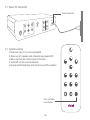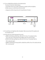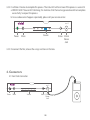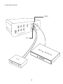
1
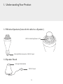
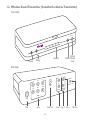
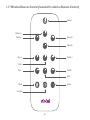
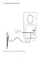
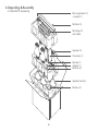
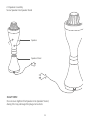
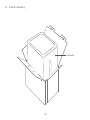
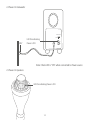
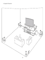
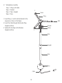
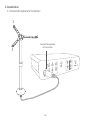
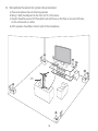
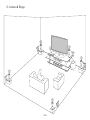
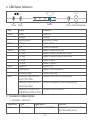
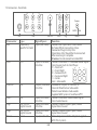
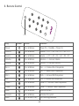
User Manual
Model Number: ECHO-WS-01
www.violet3d.com
Dear Customer,
Hearty congratulations on possessing a revolutionary 3D surround sound system which is
completely wireless and extremely convenient to install and use.
This system is such that you can place the speakers wherever convenient and unlike conventional
systems, there are no pre-fixed viewing/listening positions. The system can create theater like
sound right in your home for you to enjoy music and movies along with your family and friends.
We sincerely hope, you will continue to enjoy the performance of this system for years to come.
Should you need any clarification please do not hesitate to write to us. If you are satisfied with it,
please do tell all your friends about it. We shall be happy to arrange demonstrations for them at
their homes.
Kind regards,
Bhatia L. H.
Chairman
SNAP Networks Pvt. Ltd
Contents
1
2
3
Understanding Your Product
3
Unpacking & Assembly
8
1.1
1.2
1.3
1.4
1.5
1.6
2.1
2.2
2.3
2.4
2.5
2.6
2.7
Wireless Speakers
Speaker Stand
Wireless Sound Transmitter
Microphone
Wireless Remote Control
Wireless Subwoofer System
3
3
4
5
6
7
Echo WS-01 Unpacking
Speaker Assembly
WSub-01 Unpacking
Power On Subwoofer
Power On Speakers
Speaker Placement
Microphone Assembly
8
9
10
11
11
12
13
Installation
3.1
3.2
3.3
3.4
Connect Microphone to Transmitter
Microphone Placement for System Characterization
Power On Transmitter
System Learning
1
14
14
15
16
16
Contents
4
Connectors
18
5
Listen & Enjoy
20
6
LED Status Indicator
21
Connectors Description
21
Remote Control
23
Troubleshooting
24
7
8
9
4.1 Front Side Connector
4.2 Back Side Connector
18
19
7.1 Connectors - Front Side
7.2 Connectors - Back Side
21
22
9.1 During Normal Usage
9.2 During Learning
24
24
10 Caution
25
11 Warranty
26
12 Contact
27
2
1. Understanding Your Product
1.1 Wireless Speakers (henceforth called as a Speaker)
LED On indicating Power is ON
E26 Light Blub Connector. 230V AC Input
1.2 Speaker Stand
E26 Light Bulb Holder
230V AC Input
3
1.3. Wireless Sound Transmitter (henceforth called as Transmitter)
Front Side
aux 2
6C
Power
A1
A2
D1
D2
3.5mm
Status Stereo
Jack
Source
Mute
Back Side
L
FL
FR
SL
SR
1
C
SUB
OUT
SUB
R
Aux 1
2
Power
5A
5VDC, 1.
Dig
Ana
Mic
Mic
Sub Out
Ana
4
Aux 1 Dig 2 Dig 1
Power
1.4 Microphone
5
1.5 Wireless Remote Control (henceforth called as Remote Control)
Power
Volume +
Source -
+
Volume
-
+
Source
Source
-
Volume -
Volume
Bass +
+
-
Bass
+
Mid
Source +
+
Treble
Treble +
Mid +
Bass -
-
Bass
-
Mid
-
Treble
Treble Mid -
Mute
Learn
Unmute
6
Learn
1.6 Wireless Subwoofer System
Connect Switch
230 V
Connect
LED On indicating
Power is ON
ON
OFF
Note: Check LED is "ON" when connected to Power source
7
2. Unpacking & Assembly
2.1 Echo WS-01 Unpacking
Mic wing bracket (1)
+ coupler (1)
Mic Rods (2)
Mic Wings (3)
with Cable
Speakers (5)
Transmiter (1)
Remote (1)
Adapter (1)
Batteries (2)
Speaker Stand (5)
Mic Base (1)
8
2.2 Speaker Assembly
Screw Speaker into Speaker Stand
Speaker
Speaker Stand
CAUTION!
Do not over-tighten the Speaker into Speaker Stand,
doing this may damage the plug and sockets
9
2.3
WSub-01 Unpacking
Subwoofer
10
2.4 Power On Subwoofer
Connect Switch
230 V
Connect
LED On indicating
Power is ON
ON
OFF
Note: Check LED is "ON" when connected to Power source
2.5 Power On Speakers
LED On indicating Power is ON
11
2.6 Speaker Placement
12
2. 7 Microphone Assembly
Step-1 : Wings with cable
Step-2 : Bracket
Step-3 : Pipe+ Coupler
Step-4 : Base
2
Green
Wing
1. Insert Wing 1, 2 and 3 into the Bracket in the
sequence as shown in the figure
2. Insert the Cable through the Bracket, Pipe,
Coupler and Base
3. Tighten/Fix the Pipes to the Bracket,
Coupler and Base
1
3
Bracket
Yellow
Pipe
Coupler
Pipe
Base
Cable
13
Red
3. Installation
3.1 Connect Microphone to Transmitter
2
1
3
Connect Microphone
to Transmitter
Aux 1
14
3.2 Microphone Placement for system characterization
a) Place microphone close to listening position
b) Wing 1 (Red) should point to the front (to TV) of the room
c) Height should be around 4 ft.Place both rods with base on the floor or one rod with base
on the sofa/couch or a table.
d) All 5 speakers should be in line of sight of the microphone.
1
2
4 ft
3
15
3.3 Power On Transmitter
Power Connector
1
L
FL
FR
SL
SR
C
SUB
SUB
OUT
2
R
Aux 1
Power
A
5VDC, 1.5
Dig
Ana
Mic
3.4 System Learning
a. Make sure steps 3.1 to 3.3 are completed
b. Make sure all 5 speakers and subwoofer are powered ON
c. Make sure there are no loud noises in the room
d. Switch off any fans or air conditioners
e. Be prepared for loud tones that will come out of the speakers
+
Volume
-
+
Source
Source
-
Volume
+
Bass
-
Bass
-
+
Mid
-
Mid
+
Treble
-
Treble
Learn
Press and hold
Learn Button
16
3.4.1 Press and hold the learn button on the remote control.
The status LED will start to blink Orange.
a. Step aside such that you are NOT in between any speaker and the microphone.
b. Make sure you can see the front of the transmitter.
c. Keep quiet until the Orange Status LED stops blinking (2 minutes).
aux 2
Power
Mute
Source
Status 3.5mm
Stereo
Jack
3.4.2 You will hear set of rapid tones from all speakers. Make sure you hear all five speakers and
the subwoofer sound.
3.4.3 Observe the transmitter front panel for any error
a. ERROR CASE: Blinking of Red Status LED and ‘D1’ for 10 sec. This indicates that the
noise in the room is too loud for learning. Reduce room noise and start again.
b. ERROR CASE: Blinking of Red Status LED and ‘D2’ for 10 sec. This indicates that the
MIC has been damaged.
c. ERROR CASE: Blinking of all source LED’s and Red Status LED for 10 sec. This indicates that the
MIC is not connected.
17
3.4.4 It will take 2 minutes to complete this process. The status LED will turn Green if the process is successful
a. ERROR CASE: If Source LED’s blinking, this indicates that the learning procedure did not complete
successfully. So repeat the process.
b. In case above error happens repeatedly, please call your service center.
aux 2
Power
Source
Mute
3.4.5 Disconnect the Mic, release the wings and store in the box.
4. Connectors
4.1 Front Side Connector
aux 2
Power
Mute
Source
Status 3.5mm
Stereo
Jack
18
Status 3.5mm
Stereo
Jack
4.2 Back Side Connector
Digital 1
L
FL
FR
SL
SR
1
C
SUB
SUB
OUT
R
Aux 1
2
Power
A
5VDC, 1.5
Dig
Ana
Mic
Aux 1
DV
D
DT
H
19
Pla
ye
r
5. Listen & Enjoy
20
6. LED Status Indicators
aux 2
Power
Led
Power
Mute
Source
Status
Notes
Source
Mute
Color
Green
Orange
Blinking Green
Orange
Off
6C Blue
A1 Blue
A2 Blue
D1 Blue
D2 Blue
Green On
Blinking Red
Blinking Orange
Blinking Of Red Status LED
and D1 For 10 Sec
Blinking Of Red Status LED
and D2 For 10 Sec
Blinking Of All Source LED’s
and Red Status LED For 10 Sec
Status 3.5mm Stereo Jack
Indicator
Power On
Standby
Remote Key Pressed
System Muted
System Is Unmuted
Source Is Analog 6 Channel
Source Is Auxiliary Stereo (Back Panel)
Source Is Auxiliary Stereo (Front Panel)
Source Is Digital 1
Source Is Digital 2
System Is Ok
Speaker Is Not Powered On
System Is Learning
Indicates 'Noise' Error During Learning
Indicates 'Microphone' Error During Learning
Indicates No Mic Connected
7. Connectors Description
7.1 Connectors - Front Side
Connector
aux2
Type
3.5mm Stereo
Signal Specs
Input, Line Level, 3.3V Max
21
Function
Connect Line Level stereo audio
signal from audio source
7.2 Connectors - Back Side
FL
SL
C
FR
SR
SUB
Mic
Ana
Mic
Ana
SUB
OUT
Sub out
Connector
Mic
Type
Signal Specs
Proprietary,
Input (Mic Level)
Specific To Violet
Ana
RCA
Sub Out
RCA
Aux 1
RCA
Dig1
RCA, S/PDIF,
Digital Coaxial
RCA, S/PDIF,
Digital Coaxial
Power
Dig2
Power
L
1
R
2
Aux 1
Dig
5VDC, 1.5A
Dig
Power
Aux 1
Power
Function
Connect Mic Input Here. Care Should
Be Taken While Connecting Since
Connector Plugs In Only One
Orientation. Mic Should Be Disconnected
After Learning Is Complete
(Caution: Do not connect non-Voilet MIC)
Input, Line Level, Connect Line Level 5.1 Decoded Audio Signal
3.3v Max
From Source Such As Dvd Player.
SL
C
FL
Fl > Front Left
Fr > Front Right
Sl > Surround Left
SUB
FR
SR
Sr > Surround Right
C > Center
Ana
Sub > Subwoofer
Output, Line Level, Subwoofer Output To Connect To
3.3v Max
External Wired Active Subwoofer
(Note: Ensure Wireless Sub-woofer
Supplied With System Is Switched-off??)
Input, Line Level, Connect Line Level Stereo Audio Signal
3.3v Max
From Audio Source
Input, Line Level, Connect Coaxial Digital (Spdif) Audio
3.3v Max
Signal From Source
Input, Line Level, Connect Coaxial Digital (Spdif) Audio
3.3v Max
Signal From Source
Input, 5vdc 1.5A
(Note: Only Connect The Adaptor Supplied
With This System)
22
me
Bass
-
+
Bass
-
-
Mid
-
Sour
ce
Mid
+
Lea
rn
-
Volu
Volu
+
Treb
le
me
+
Treb
le
+
Sour
ce
8. Remote Control
Power
Key
Symbol
Power
Action
Function
Press & Release
Power On -> Standby -> Power On
Source +
+
Source
Press & Release
Source + => D1 -> D2 -> 6C -> A1 -> A2 -> D1
Source -
Source
Press & Release
Source - => D1 -> A2 -> A1 -> 6C -> D2 -> D1
Volume +
+
Volume
Press & Release
Volume + => Increase Volume
Volume -
Volume
Press & Release
Volume - => Decrease Volume
Bass +
+
Bass
Press & Release
Bass + => Increase Bass Frequencies
Bass -
Bass
Press & Release
Bass - => Reduce Bass Frequencies
Mid +
+
Mid
Press & Release
Mid + => Increase Mid Frequencies
Mid -
Mid
Press & Release
Mid - => Reduce Mid Frequencies
Treble +
+
Treble
Press & Release
Treble + => Increase Treble Frequencies
Treble -
Treble
Press & Release
Treble - => Reduce Treble Frequencies
Mute
Press & Release
Mute the system
Unmute
Learn
Press & Release
Press & Hold (2 sec)
Unmutes the system
Start learning procedure
Learn
23
9. Troubleshooting
9.1 During Normal Usage
1. Status LED is RED or Blinking RED
• If Status LED is Blinking RED, some speakers have been turned off.
2. Speech sound seems to come more from back than front
• Repeat Learning procedure again.
3. There is no sound
• Check connections & source
• Check Mute Status
• Try increasing the Volume
4. If no sound in speakers with digital source, make sure connector is connected with DVD player
and RESET the transimitter once with the DVD player running.
9.2 During Learning
1. Blinking of Red Status LED and D1 for 10 sec.
• This indicates that the noise in the room is too loud for learning. Reduce noise and start again.
2. Blinking of Red Status LED and D2 for 10 sec.
• This indicates that there is something wrong with the microphone. Please call your
service center.
3. Blinking of all Source LED’s and Red Status LED for 10 sec.
• This indicates that microphone is not connected. If this repeats Please call your service center.
4. If Source LED is blinking.
• Learning procedure did not complete successfully. Repeat the process. In case error
happens repeatedly, call your service center.
24
10. Caution
Caution 1:
servicing to
To reduce the risks of electric shock do not open device. No user-serviceable parts inside, refer
qualified service personnel.
The speaker system is not intended for use by children without supervision.
The system should not be exposed to water (dripping or splashing) and no objects filled with
liquids, such as
vases, should be placed on any part of the system.
Caution 4:
To prevent fire or electric shock hazard, do not expose this product to rain or moisture.
Caution 2:
Caution 3:
SAFETY WARNINGS:
AC-DC ADAPTER WARNING:
• To reduce risk of electric shock, do not expose AC adapter to rain, moisture, liquid, or heat sources (e.g. radiators,
heat registers, stoves, amplifiers, etc).
• AC-DC adapter is for indoor use only.
• Do not use any other AC-DC adapter with the product.
• Do not use a damaged AC-DC adapter or attempt to repair one.
• Inspect AC-DC adapter regularly for cable, plug, or casing damage.
POWER CORD WARNING:
• If the system is supplied with an extension cord or an electrical portable outlet device, the extension cord
or electrical portable outlet device must be positioned so that it is not subject to splashing
or ingress of moisture.
• It is recommended that most appliances be placed on a dedicated circuit. That is, a single power outlet
component which powers only that appliance and has no additional outlets or branch circuits.
• Protect the power cord from physical or mechanical abuse such as being twisted, kinked, pinched, closed
in
a door, or walked upon. Pay particular attention to plugs, wall outlets and point where the cord is
connected.
• Do not overload wall outlets. Overloaded wall outlets, loose or damaged wall outlets, extension cords,
frayed power cords, damaged or cracked wire insulations are dangerous, Any of these conditions could
result
25
BATTERY WARNING:
• Risk of explosion and personal injury if batteries are replaced by incorrect type in Violet remote control.
• Do not open, mutilate, or expose to conducting materials (metal), moisture, liquid, fire, or heat (above 54oC or
130oF). Doing so may cause batteries to leak or explode, resulting in personal injury.
• Dispose of spent, leaking, or damaged batteries according to manufacture instructions and local laws.
• Store away from children in a cool, dry place at room temperature.
11. Warranty
Limited warranty:
SNAP Networks warrants that your product hardware shall be free from defects in material and workmanship for
one year, beginning from the date of purchase. Except where prohibited by applicable law, this warranty is
nontransferable and is limited to the original purchaser. This warranty gives you specific legal rights and you may
also have other rights that vary under local law.
This warranty does not cover problems or damage resulting from (1) Accident, lightning, water, fire, heat, abuse,
and misapplication or any unauthorized repair, modification or disassembly, (2) Improper operation or maintenance, usage not in accordance with product instructions or connection to improper voltage supply, (3) The serial
number is deleted, defaced or altered, or, (4) Use of consumables, such as replacement batteries, not supplied by
SNAP Networks except where such restriction is prohibited by applicable law.
Remedies:
SNAP Networks entire liability and your exclusive remedy for any breach of warranty shall be at company option,
to repair or replace the hardware, provided that the hardware is returned to the point of purchase or such other
place as SNAP Networks may direct with a copy of the sales receipt and/or local warranty card. Shipping and
handling charges may apply except where prohibited by applicable law. SNAP Networks may at its option, use new
or refurbished or used parts in good working condition to repair or replace any hardware product. Any replacement hardware product will be warranted for at least the remainder of the warranty period.
How to obtain warranty support:
Before submitting warranty claim, we recommend you visit the support section at http://www.violet3d.com for
technical assistance. Valid warranty claims are generally processed through the point of purchase during the first one
year after purchase; however, this period of time may vary depending on where you purchased your product – please
check with SNAP Networks or the retailer where you purchased your product for details.
26
Warranty claims that cannot be processed through the point of purchase and any other product related questions
should be addressed directly to the company. The addresses and customer service contact information for SNAP
Networks can be found in the documentation accompanying your product and on the web at
http://www.violet3d.com.
Limitation of liability:
SNAP Networks shall not be liable for any special, indirect, incidental or consequential damages whatsoever,
including but not limited to loss of profits, revenue or data (whether direct or indirect) or commercial loss for
breach of any express or implied warranty on your product even if SNAP Networks has been advised of the
possibility of such damages. Some jurisdictions do not allow the exclusion or limitation of special, indirect,
incidental or consequential damages, so the above limitation or exclusion may not apply to you.
Duration of implied warranties
Except to the extent prohibited by applicable law, any implied warranty or condition of merchantability or fitness
for a particular purpose on this hardware product is limited in duration to the applicable limited warranty period
for your product. Some jurisdictions do not allow limitations on how long an implied warranty lasts, so the above
limitation may not apply to you.
National statutory rights
Consumers have legal rights under applicable national legislation governing the sale of consumer goods Such
rights are not affected by the warranties in this Limited Warranty.
No other warranties
None of the SNAP Networks dealers, agents, or employees are authorized to make any modification, extension or
addition to this warranty.
Contact Address:
Customer Care
SNAP Networks Pvt Ltd. 734, 1st Floor,
22nd Main, 12th Cross, JP Nagar Phase 2, Bangalore 560 078, India
Mob: +91 90081 01043. Email: [email protected]
www.violet3d.com
27
Contact Address:
Customer Care
VIOLET
#294/22,7th Cross, Jayanagar 1st Block, Bangalore 560011.
Mob: +91 90081 01043. Email: [email protected]
www.violet3d.com
For further details contact :
Customer Care
VIOLET
#294/22,7th Cross, Jayanagar 1st Block, Bangalore 560011.
Mob: +91 90081 01043. Email: [email protected]
www.violet3d.com