1
Preface
SIMATIC HMI HMI Device TP 177A, TP 177B, OP 177B (WinCC flexible)
1
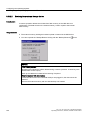
Overview
______________
SIMATIC HMI
HMI Device
TP 177A, TP 177B, OP 177B
(WinCC flexible)
Operating Instructions
Safety Instructions and
General Notes
2
______________
3
Planning Use
______________
4
Installation and connection
______________
Operator Controls and
Displays
5
______________
Configuring the Operating
System
6
______________
7
Commissioning a project
______________
8
Operating a Project
______________
9
Operating Alarms
______________
10
Operating Recipes
______________
11
Maintenance and care
______________
12
Specifications
______________
A
Appendix
______________
Order no.: 6AV6691-1DG01-0AB1
08/2008
A5E01006556-03
B
Abbreviations
______________
Safety Guidelines
Safety Guidelines
This manual contains notices you have to observe in order to ensure your personal safety, as well as to prevent
damage to property. The notices referring to your personal safety are highlighted in the manual by a safety alert
symbol, notices referring only to property damage have no safety alert symbol. These notices shown below are
graded according to the degree of danger.
DANGER
indicates that death or severe personal injury will result if proper precautions are not taken.
WARNING
indicates that death or severe personal injury may result if proper precautions are not taken.
CAUTION
with a safety alert symbol, indicates that minor personal injury can result if proper precautions are not taken.
CAUTION
without a safety alert symbol, indicates that property damage can result if proper precautions are not taken.
NOTICE
indicates that an unintended result or situation can occur if the corresponding information is not taken into
account.
If more than one degree of danger is present, the warning notice representing the highest degree of danger will
be used. A notice warning of injury to persons with a safety alert symbol may also include a warning relating to
property damage.
Qualified Personnel
The device/system may only be set up and used in conjunction with this documentation. Commissioning and
operation of a device/system may only be performed by qualified personnel. Within the context of the safety notes
in this documentation qualified persons are defined as persons who are authorized to commission, ground and
label devices, systems and circuits in accordance with established safety practices and standards.
Prescribed Usage
Note the following:
WARNING
This device may only be used for the applications described in the catalog or the technical description and only
in connection with devices or components from other manufacturers which have been approved or
recommended by Siemens. Correct, reliable operation of the product requires proper transport, storage,
positioning and assembly as well as careful operation and maintenance.
Trademarks
All names identified by ® are registered trademarks of the Siemens AG. The remaining trademarks in this
publication may be trademarks whose use by third parties for their own purposes could violate the rights of the
owner.
Disclaimer of Liability
We have reviewed the contents of this publication to ensure consistency with the hardware and software
described. Since variance cannot be precluded entirely, we cannot guarantee full consistency. However, the
information in this publication is reviewed regularly and any necessary corrections are included in subsequent
editions.
Siemens AG
Industry Sector
Postfach 48 48
90327 NÜRNBERG
GERMANY
Ordernumber: 6AV6691-1DG01-0AB1
Ⓟ 08/2008
Copyright © Siemens AG 2008.
Technical data subject to change
Preface
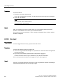
Purpose of the Operating Instructions
These operating instructions provide information based on the requirements defined by
DIN EN 62079 for mechanical engineering documentation. The information relates to the
HMI device, its place of use, transportation, storage, installation, use, and maintenance.
These operating instructions are intended for:
● Users
● Commissioning engineers
● Service technicians
● Maintenance technicians
Please read the section "Safety instructions and general notes" carefully.
The help integrated in WinCC flexible, the WinCC flexible Information System, contains
detailed information. The information system contains instructions, examples and reference
information in electronic form.
Basic Knowledge Requirements
General knowledge of automation technology and process communication is needed to
understand the operating instructions.
It is also assumed that those using the manual have experience in using personal computers
and knowledge of Microsoft operating systems.
Range of Validity for the Operating Instructions
These operating instructions apply to the HMI devices TP 177A, TP 177B and OP 177B in
combination with the WinCC flexible software package.
TP 177A, TP 177B, OP 177B (WinCC flexible)
Operating Instructions, 08/2008, 6AV6691-1DG01-0AB1
3
Preface
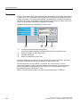
Position in the Information Scheme
These operating instructions form part of the SIMATIC HMI documentation. The following
provides an overview of the information landscape for SIMATIC HMI.
User manuals
● WinCC flexible Micro
Describes the basics of configuration with the WinCC flexible Micro engineering system.
● WinCC flexible Compact/Standard/Advanced
Describes basic principles of configuration using the WinCC flexible Compact/
WinCC flexible Standard/WinCC flexible Advanced engineering systems.
● WinCC flexible Runtime
Describes how to commission and operate your runtime project on a PC.
● WinCC flexible Migration
– Describes how to convert an existing ProTool project to WinCC flexible.
– Describes how to convert an existing WinCC project to WinCC flexible.
– Describes how to convert an existing ProTool project including a change of the
HMI device, for example from OP3 to OP 73 or from OP7 to OP 77B
– Describes how to convert an existing ProTool project including a change from a
graphics device to a Windows CE device.
● Communication
– Communication Part 1 describes the connection of the HMI device to SIMATIC PLCs.
– Communication Part 2 describes the connection of the HMI device to third-party
controllers.
4
TP 177A, TP 177B, OP 177B (WinCC flexible)
Operating Instructions, 08/2008, 6AV6691-1DG01-0AB1
Preface
Operating instructions
● Operating instructions for SIMATIC HMI devices.
– OP 73, OP 77A, OP 77B
– TP 170micro, TP 170A, TP 170B, OP 170B
– OP 73micro, TP 177micro
– TP 177A, TP 177B, OP 177B
– TP 270, OP 270
– MP 270B
– MP 277
– MP 370
– MP 377
● Operating instructions for mobile SIMATIC HMI devices
– Mobile Panel 170
– Mobile Panel 177
– Mobile Panel 277
● Operating Instructions(Compact) for SIMATIC HMI devices
– OP 77B
– Mobile Panel 170
– Mobile Panel 177
Getting Started
● WinCC flexible for first time users
Based on an example project, this is a step-by-step introduction to the basics of
configuring screens, alarms, recipes and screen navigation.
● WinCC flexible for power users
Based on an example project, this is a step-by-step introduction to the basics of
configuring logs, project reports, scripts, user management, multilingual projects and
integration in STEP 7.
● WinCC flexible Options
Based on an example project, this is a step-by-step introduction to the basics of
configuring the WinCC flexible Sm@rtServices, Sm@rtAccess and OPC server options.
Online Availability
Technical documentation on SIMATIC products and SIMATIC systems is available in
PDF format in various languages at the following addresses:
● SIMATIC Guide Technical Documentation:
"http://www.automation.siemens.com/simatic/portal/html_00/techdoku.htm"
TP 177A, TP 177B, OP 177B (WinCC flexible)
Operating Instructions, 08/2008, 6AV6691-1DG01-0AB1
5
Preface
Conventions
Configuration and runtime software differ with regard to their names as follows:
● "WinCC flexible 2008," for example, refers to the configuration software.
The term "WinCC flexible" is used in a general context. The full name, for example
"WinCC flexible 2008", is always used when it is necessary to differentiate between
different versions of the configuration software.
● "WinCC flexible Runtime" refers to the runtime software that can run on HMI devices.
The name "TP 177B" is the umbrella term for the following HMI devices:
● TP 177B 4"
● TP 177B 6"
Text is highlighted as follows to simplify reading the operating instructions:
Notation
Scope
"Add screen"
•
•
•
Terms that appear in the user interface, for example,
dialog names, tabs, buttons, menu commands
Required input, for example, limits, tag values.
Path information
"File > Edit"
Operator actions, for example, menu commands, shortcut menu
commands.
<F1>, <Alt+P>
Keyboard operation
Please observe notes labeled as follows:
Note
Notes contain important information concerning the product, its use or a specific section of
the documentation to which you should pay particular attention.
Trademarks
Names labeled with a ® symbol are registered trademarks of the Siemens AG. Other names
used in this documentation may be trademarks, the use of which by third parties for their
own purposes could violate the rights of the owner.
● HMI®
● SIMATIC®
● SIMATIC HMI®
● SIMATIC ProTool®
● SIMATIC WinCC®
● SIMATIC WinCC flexible®
● SIMATIC TP 177A®
● SIMATIC TP 177B®
● SIMATIC OP 177B®
6
TP 177A, TP 177B, OP 177B (WinCC flexible)
Operating Instructions, 08/2008, 6AV6691-1DG01-0AB1
Preface
Representatives and offices
If you have any further questions relating to the products described in this manual,
please contact your local representative at the SIEMENS branch nearest you.
You can locate your contact partner on this Internet URL:
"http://www.siemens.com/automation/partner"
Training Center
Siemens AG offers a variety of training courses to familiarize you with automation systems.
Please contact your regional Training Center, or the central Training Center in
D90327 Nuremberg.
Phone: +49 (911) 895-3200
Internet: "http://www.sitrain.com"
Technical Support
You can reach the Technical Support for all A&D products
using the support request form on the web:
"http://www.siemens.de/automation/support-request"
Phone: + 49 180 5050 222
Fax: + 49 180 5050 223
For further information about Siemens Technical Support, refer to the Internet at
"http://www.siemens.com/automation/support-request"
Service & Support on the Internet
Service & Support provides additional comprehensive information on SIMATIC products
through online services at "http://support.automation.siemens.com:"
● The newsletter provides up-to-date information relating to your products.
● Our Service & Support search engine provides you access to all available documentation.
● A forum for global exchange of information by users and experts
● Current product information, FAQs and downloads
● Your local Automation & Drives representative
● Information about on-site services, repairs, spare parts and much more is available on
our "Services" pages.
TP 177A, TP 177B, OP 177B (WinCC flexible)
Operating Instructions, 08/2008, 6AV6691-1DG01-0AB1
7
Preface
8
TP 177A, TP 177B, OP 177B (WinCC flexible)
Operating Instructions, 08/2008, 6AV6691-1DG01-0AB1
Table of contents
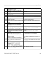
Preface ...................................................................................................................................................... 3
1
2
3
4
Overview.................................................................................................................................................. 15
1.1
Product Overview.........................................................................................................................15
1.2
Design of the TP 177A HMI Device .............................................................................................16
1.3
Design of the TP 177B 6" HMI device .........................................................................................17
1.4
Design of the TP 177B 4" HMI device .........................................................................................19
1.5
Design of the OP 177B HMI Device ............................................................................................20
1.6
Accessories..................................................................................................................................22
1.7
Miscellaneous ..............................................................................................................................22
1.8
Functional scope with WinCC flexible..........................................................................................23
1.9
Software options ..........................................................................................................................26
1.10
Communication Using the TP 177A.............................................................................................26
1.11
Communication Using the TP 177B and OP 177B ......................................................................27
Safety Instructions and General Notes .................................................................................................... 29
2.1
Safety Information........................................................................................................................29
2.2
Standards and Approvals.............................................................................................................30
2.3
Notes about Usage ......................................................................................................................33
2.4
Electromagnetic Compatibility......................................................................................................36
2.5
Transport and Storage Conditions ...............................................................................................38
Planning Use ........................................................................................................................................... 39
3.1
Mounting Information ...................................................................................................................39
3.2
Mounting Positions and Fixation ..................................................................................................41
3.3
Preparing for Mounting ................................................................................................................43
3.4
Specifications for Insulation Tests, Protection Class and Degree of Protection..........................45
3.5
Nominal Voltages.........................................................................................................................45
Installation and connection ...................................................................................................................... 47
4.1
Checking the package contents...................................................................................................47
4.2
Mounting the HMI Device.............................................................................................................47
4.3
4.3.1
4.3.2
4.3.3
4.3.4
Connecting the HMI Device .........................................................................................................50
Interfaces on the TP 177A ...........................................................................................................51
Interfaces on the TP 177B 4".......................................................................................................51
Interfaces on the TP 177B 6".......................................................................................................52
Interfaces on the OP 177B...........................................................................................................52
TP 177A, TP 177B, OP 177B (WinCC flexible)
Operating Instructions, 08/2008, 6AV6691-1DG01-0AB1
9
Table of contents
5
6
10
4.3.5
4.3.6
4.3.7
4.3.8
4.3.9
4.3.10
4.3.11
Connecting the Equipotential Bonding Circuit............................................................................. 53
Connecting the Power Supply..................................................................................................... 55
Connecting uninterruptible power supply on the TP 177B 4" ..................................................... 58
Connecting the Controller ........................................................................................................... 58
Connecting a configuration PC ................................................................................................... 61
Connecting USB devices to TP 177B and OP 177B .................................................................. 65
Connecting printers to TP 177B and OP 177B ........................................................................... 66
4.4
Switching on and Testing the HMI Device .................................................................................. 68
Operator Controls and Displays............................................................................................................... 71
5.1
Front-side Operator Controls ...................................................................................................... 71
5.2
Connecting a memory card to the TP 177B 6" and OP 177B..................................................... 73
5.3
Insert a memory card in the TP 177B 4" ..................................................................................... 76
5.4
Labeling function keys on the TP 177B 4" and OP 177B ........................................................... 78
Configuring the Operating System ........................................................................................................... 81
6.1
6.1.1
6.1.2
6.1.2.1
6.1.2.2
6.1.2.3
6.1.2.4
6.1.2.5
6.1.2.6
6.1.2.7
6.1.2.8
6.1.2.9
Configuring the Operating System on the TP 177A.................................................................... 81
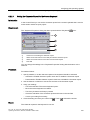
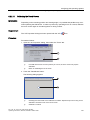
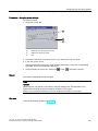
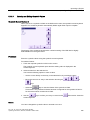
Overview ..................................................................................................................................... 81
Control Panel .............................................................................................................................. 82
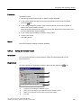
Overview ..................................................................................................................................... 82
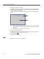
Changing Screen Settings .......................................................................................................... 84
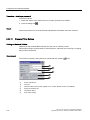
Displaying Information about the HMI Device............................................................................. 86
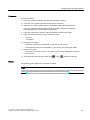
Calibrating the Touch Screen ..................................................................................................... 87
Display License Information ........................................................................................................ 89
Changing the Password Settings................................................................................................ 89
Changing MPI/DP Settings ......................................................................................................... 91
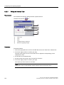
Setting the Screen Saver ............................................................................................................ 92
Configuring the Data Channel..................................................................................................... 93
6.2
6.2.1
6.2.2
6.2.2.1
6.2.2.2
6.2.2.3
6.2.2.4
6.2.2.5
6.2.2.6
6.2.2.7
6.2.2.8
6.2.2.9
6.2.2.10
6.2.2.11
6.2.2.12
6.2.2.13
6.2.2.14
6.2.2.15
6.2.2.16
6.2.2.17
6.2.2.18
6.2.2.19
6.2.2.20
6.2.2.21
6.2.2.22
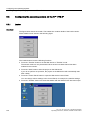
Configuring the operating system for TP 177B 6" and OP 177B................................................ 96
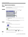
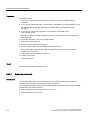
Overview ..................................................................................................................................... 96
Control Panel .............................................................................................................................. 98
Overview ..................................................................................................................................... 98
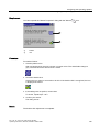
Input Using the Screen Keyboard ............................................................................................. 100
Configuring the Screen Keyboard............................................................................................. 101
Setting the Character Repeat for the Screen Keyboard ........................................................... 103
Setting the Double-click on the Touch Screen.......................................................................... 104
Backup and Restore Using a Memory Card ............................................................................. 105
Setting the Date and Time ........................................................................................................ 108
Saving Registry Information ...................................................................................................... 109
Changing Screen Contrast........................................................................................................ 111
Displaying Information about the HMI Device........................................................................... 112
Calibrating the Touch Screen ................................................................................................... 113
Changing the Password Settings.............................................................................................. 115
Changing Printer Settings ......................................................................................................... 116
Changing Regional Settings ..................................................................................................... 118
Changing MPI/PROFIBUS DP Settings.................................................................................... 119
Setting the Delay Time.............................................................................................................. 123
Setting the Screen Saver .......................................................................................................... 124
Displaying System Information ................................................................................................. 125
Configuring the Data Channel................................................................................................... 126
Overview of Network Operation ................................................................................................ 129
Setting the Device Name of the HMI Device............................................................................. 131
Activating a Direct Connection.................................................................................................. 132
TP 177A, TP 177B, OP 177B (WinCC flexible)
Operating Instructions, 08/2008, 6AV6691-1DG01-0AB1
Table of contents
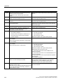
6.2.2.23 Changing Network Settings .......................................................................................................133
6.2.2.24 Changing the Logon Information................................................................................................135
6.2.2.25 Changing Internet Settings ........................................................................................................136
6.3
6.3.1
6.3.2
6.3.3
6.3.3.1
6.3.3.2
6.3.3.3
6.3.3.4
6.3.3.5
6.3.4
6.3.4.1
6.3.4.2
6.3.4.3
6.3.4.4
6.3.5
6.3.6
6.3.6.1
6.3.6.2
6.3.6.3
6.3.6.4
6.3.6.5
6.3.6.6
6.3.6.7
6.3.6.8
6.3.6.9
6.3.6.10
6.3.6.11
6.3.7
6.3.8
6.3.9
6.3.10
6.3.10.1
6.3.10.2
6.3.11
6.3.11.1
6.3.11.2
6.3.11.3
6.3.11.4
6.3.11.5
6.3.11.6
6.3.12
6.3.12.1
6.3.12.2
6.3.13
7
Configuring the operating system on the TP 177B 4"................................................................138
Loader ........................................................................................................................................138
Setting up and disabling SecureMode .......................................................................................140
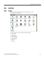
Control Panel .............................................................................................................................141
Overview ....................................................................................................................................141
Opening the Control Panel.........................................................................................................142
Reference for functions..............................................................................................................142
Operator control options for the Control Panel ..........................................................................144
Operating the Control Panel with the touch screen ...................................................................144
Changing settings for operation .................................................................................................146
Configuring the screen keyboard ...............................................................................................146
Setting the character repeat.......................................................................................................147
Setting the double-click..............................................................................................................148
Calibrating the touch screen ......................................................................................................150
Changing password protection ..................................................................................................151
Changing the HMI device settings .............................................................................................153
Setting the date and time ...........................................................................................................153
Changing regional settings ........................................................................................................155
Backup registry information .......................................................................................................156
Changing monitor settings .........................................................................................................157
Setting the screen saver ............................................................................................................158
Changing the printer properties .................................................................................................160
Restarting the HMI device..........................................................................................................162
Displaying information about the HMI device ............................................................................164
Displaying system properties .....................................................................................................165
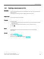
Displaying memory distribution ..................................................................................................166
Activate memory management ..................................................................................................167
Setting storage location .............................................................................................................168
Setting the delay time ................................................................................................................169
Enabling PROFINET IO .............................................................................................................170
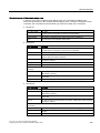
Changing transfer settings .........................................................................................................172
Configuring the data channel .....................................................................................................172
Changing MPI/PROFIBUS DP settings .....................................................................................175
Network operation......................................................................................................................178
Overview ....................................................................................................................................178
Setting the device name of the HMI device ...............................................................................180
Changing the network configuration ..........................................................................................181
Changing the logon data............................................................................................................183
Changing e-mail settings ...........................................................................................................184
Importing and deleting certificates .............................................................................................185
Backup and restore....................................................................................................................186
Saving to external storage device (backup)...............................................................................186
Restoring from external storage device .....................................................................................188
Setting the uninterruptible power supply....................................................................................190
Commissioning a project ....................................................................................................................... 193
7.1
7.1.1
7.1.2
7.1.3
Overview ....................................................................................................................................193
Setting the Operating Mode .......................................................................................................195
Reusing Existing Projects ..........................................................................................................196
Data Transmission Options........................................................................................................197
7.2
7.2.1
Transfer......................................................................................................................................198
Overview ....................................................................................................................................198
TP 177A, TP 177B, OP 177B (WinCC flexible)
Operating Instructions, 08/2008, 6AV6691-1DG01-0AB1
11
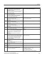
Table of contents
8
12
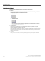
7.2.2
7.2.3
7.2.4
Starting Manual Transfer........................................................................................................... 199
Starting Automatic Transfer ...................................................................................................... 200
Testing a Project ....................................................................................................................... 202
7.3
7.3.1
7.3.2
7.3.3
Backup and Restore.................................................................................................................. 203
Overview ................................................................................................................................... 203
Backup and Restore using WinCC flexible ............................................................................... 204
Backup and Restore using ProSave ......................................................................................... 206
7.4
7.4.1
7.4.2
7.4.3
7.4.4
Updating operating systems on the TP 177A, TP 177B 6" and OP 177B ................................ 208
Overview ................................................................................................................................... 208
Resetting to factory settings...................................................................................................... 209
Updating the operating system with WinCC flexible ................................................................. 209
Updating the operating system with ProSave ........................................................................... 211
7.5
7.5.1
7.5.2
7.5.3
7.5.4
7.5.5
7.5.6
Updating the operating system on the TP 177B 4"................................................................... 212
Overview ................................................................................................................................... 212
Resetting factory settings.......................................................................................................... 213
Updating the operating system using WinCC flexible............................................................... 214
Updating the operating system using ProSave......................................................................... 215
Resetting to factory settings with WinCC flexible ..................................................................... 216
Resetting to factory settings with ProSave ............................................................................... 218
7.6
7.6.1
7.6.2
7.6.3
Installing and Removing Options .............................................................................................. 221
Overview ................................................................................................................................... 221
Installing and Removing Options using WinCC flexible............................................................ 221
Installing and removing options using ProSave........................................................................ 223
7.7
7.7.1
7.7.2
Transfering License Keys and Transfering Them Back............................................................ 224
Overview ................................................................................................................................... 224
Transferring and transferring back license keys ....................................................................... 225
Operating a Project................................................................................................................................ 227
8.1
8.1.1
8.1.2
8.1.3
8.1.3.1
8.1.3.2
8.1.3.3
8.1.3.4
8.1.3.5
8.1.3.6
8.1.4
8.1.4.1
8.1.4.2
8.1.4.3
8.1.4.4
8.1.4.5
8.1.4.6
8.1.5
8.1.6
8.1.6.1
8.1.6.2
Operating a Project on the TP 177A ......................................................................................... 227
Overview ................................................................................................................................... 227
Setting the Project Language.................................................................................................... 229
Entries and Help within a Project .............................................................................................. 230
Overview ................................................................................................................................... 230
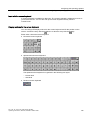
Entering and Editing Numerical Values .................................................................................... 231
Entering and Editing Alphanumerical Values............................................................................ 233
Entering and Editing Symbolic Values ...................................................................................... 235
Entering and Modifying the Date and Time............................................................................... 236
Viewing infotext ......................................................................................................................... 236
Project security.......................................................................................................................... 237
Overview ................................................................................................................................... 237
User logon................................................................................................................................. 239
User logoff................................................................................................................................. 240
Create user ............................................................................................................................... 241
Changing user data................................................................................................................... 242
Deleting a user .......................................................................................................................... 243
Closing the project .................................................................................................................... 244
Operating the Trend View ......................................................................................................... 244
Overview ................................................................................................................................... 244
Operating the Trend View ......................................................................................................... 245
8.2
8.2.1
8.2.2
8.2.3
Operating a project on TP 177B and OP 177B......................................................................... 246
Overview ................................................................................................................................... 246
Operating keys on the TP 177B 4" and OP 177B..................................................................... 248
Direct keys ................................................................................................................................ 249
TP 177A, TP 177B, OP 177B (WinCC flexible)
Operating Instructions, 08/2008, 6AV6691-1DG01-0AB1
Table of contents
8.2.4
8.2.5
8.2.5.1
8.2.5.2
8.2.5.3
8.2.5.4
8.2.5.5
8.2.5.6
8.2.5.7
8.2.6
8.2.7
8.2.8
8.2.9
8.2.10
8.2.11
8.2.11.1
8.2.11.2
8.2.12
8.2.12.1
8.2.12.2
8.2.12.3
8.2.12.4
8.2.12.5
8.2.12.6
8.2.13
9
10
Setting the project language ......................................................................................................250
Entries and help within a project ................................................................................................250
Overview ....................................................................................................................................250
Entering numerical values on the TP 177A, TP 177B and OP 177B.........................................252
Entering alphanumerical values on the TP 177A, TP 177B 6" and OP 177B ...........................254
Entering alphanumerical values on the TP 177B 4" ..................................................................256
Entering and editing symbolic values ........................................................................................258
Entering the Date and Time .......................................................................................................258
Viewing Infotext..........................................................................................................................259
Operating a Gauge ....................................................................................................................260
Using Switches...........................................................................................................................261
Using a Slider.............................................................................................................................262
Using the Status Force Display..................................................................................................263
Operating the Sm@rtClient View...............................................................................................265
Operating Trends .......................................................................................................................267
Overview ....................................................................................................................................267
Operating the Trend View ..........................................................................................................268
Project Security ..........................................................................................................................269
Overview ....................................................................................................................................269
User Logon.................................................................................................................................271
User Logoff.................................................................................................................................272
Creating a User ..........................................................................................................................273
Changing User Data ..................................................................................................................274
Deleting a User ..........................................................................................................................276
Closing the Project.....................................................................................................................278
Operating Alarms................................................................................................................................... 279
9.1
9.1.1
9.1.2
9.1.3
9.1.4
Operating Alarms TP 177A ........................................................................................................279
Overview ....................................................................................................................................279
Displaying Alarms ......................................................................................................................280
Acknowledging Alarms...............................................................................................................282
Editing Alarms ............................................................................................................................283
9.2
9.2.1
9.2.2
9.2.3
9.2.4
Operating Alarms on TP 177B and OP 177B ............................................................................284
Overview ....................................................................................................................................284
Displaying Alarms ......................................................................................................................285
Acknowledging Alarms...............................................................................................................288
Editing Alarms ............................................................................................................................289
Operating Recipes ................................................................................................................................. 291
10.1
Overview ....................................................................................................................................291
10.2
Structure of a recipe...................................................................................................................292
10.3
Recipes in the Project ................................................................................................................294
10.4
Displaying a Recipe ...................................................................................................................296
10.5
Recipe Values in the HMI Device and the PLC .........................................................................299
10.6
10.6.1
10.6.2
10.6.3
10.6.4
10.6.5
10.6.6
10.6.7
Operating the Enhanced Recipe View.......................................................................................300
Overview ....................................................................................................................................300
Creating a recipe data record ....................................................................................................302
Editing a recipe data record .......................................................................................................303
Deleting a recipe data record.....................................................................................................304
Synchronizing Tags on the TP 177B and OP 177B...................................................................305
Reading a recipe data record from the PLC ..............................................................................306
Transferring a recipe data record to the PLC ............................................................................307
TP 177A, TP 177B, OP 177B (WinCC flexible)
Operating Instructions, 08/2008, 6AV6691-1DG01-0AB1
13
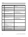
Table of contents
11
12
A
B
10.7
10.7.1
10.7.2
10.7.3
10.7.4
10.7.5
10.7.6
Operating the Simple Recipe View ........................................................................................... 308
Overview ................................................................................................................................... 308
Creating a Recipe Data Record ................................................................................................ 310
Editing a Recipe Data Record................................................................................................... 311
Deleting a Recipe Data Record ................................................................................................ 312
Reading a Recipe Data Record from the PLC .......................................................................... 313
Transferring a Recipe Data Record to the PLC ........................................................................ 314
10.8
Exporting Recipe Data Records on the TP 177B and OP 177B............................................... 315
10.9
Importing Recipe Data Records on the TP 177B and OP 177B ............................................... 316
Maintenance and care ........................................................................................................................... 317
11.1
11.1.1
11.1.2
11.1.3
11.1.4
Maintenance and Service.......................................................................................................... 317
Maintenance and care............................................................................................................... 317
Clean screen on the TP 177A and TP 177B 6" ........................................................................ 318
Protective Membrane ................................................................................................................ 318
Protective covers on the TP 177A and TP 177B 6" .................................................................. 319
11.2
Service and spare parts ............................................................................................................ 323
Specifications ........................................................................................................................................ 325
12.1
Dimension drawings of the TP 177B 4" .................................................................................... 325
12.2
Dimension drawings of the TP 177A and TP 177B 6" .............................................................. 326
12.3
Dimension Drawings of the OP 177B ....................................................................................... 327
12.4
Specifications of the TP 177A................................................................................................... 328
12.5
Technical specifications of the TP 177B 4"............................................................................... 329
12.6
Technical specifications of the TP 177B 6"............................................................................... 330
12.7
Specifications of the OP 177B .................................................................................................. 331
12.8
12.8.1
12.8.2
12.8.3
12.8.4
Description of the Interfaces ..................................................................................................... 332
Power Supply ............................................................................................................................ 332
X10/IF 1B (RS 422/RS 485)...................................................................................................... 332
X20 (USB) ................................................................................................................................. 333
X1 (PROFINET) ........................................................................................................................ 333
Appendix................................................................................................................................................ 335
A.1
ESD Guidelines......................................................................................................................... 335
A.2
System Alarms .......................................................................................................................... 337
Abbreviations......................................................................................................................................... 363
Glossary ................................................................................................................................................ 365
Index...................................................................................................................................................... 371
14
TP 177A, TP 177B, OP 177B (WinCC flexible)
Operating Instructions, 08/2008, 6AV6691-1DG01-0AB1
1
Overview
1.1
Product Overview
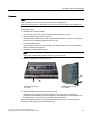
Advanced applications with the Touch Panels TP 177A, TP 177B and OP 177B
The 177 series of panels represents a further advance in the development of the well-known
170 HMI devices. The new TP 177A, TP 177B and OP 177B panels make for more efficient
use of text or graphic-based projects for simple to medium level HMI operating and
monitoring tasks in machines and plants. Projects with Asian and Cyrillic character sets can
be configured, as usual. The ability to vertically mount the TP 177A and the non-volatile
alarm buffer of the TP 177B offer new application possibilities. In addition, the TP 177B and
OP 177B – depending on the models – provide interfaces for connecting to PROFIBUS and
PROFINET.
The TP 177B 4" features a 4.3" TFT display with wide-screen format. This display extends
the visible area on the HMI device by approximately 25 % compared to similar displays with
4:3 format. The HMI device also features four function keys with tactile feedback.
In combination with the intuitive touch operation, it offers maximum operating efficiency.
In addition to MMC cards, the TP 177B 4" supports SD cards and USB memory sticks.
OP 177B offers an additional feature. It can now be operated using widely-available touch
screens in addition to the membrane keyboard. The function keys can be configured to
system keys for specific screens.
The TP 177A, TP 177B and OP 177B panels offer quick commissioning times, large user
memory and high performance, and they are optimized for projects based on WinCC flexible.
TP 177A, TP 177B, OP 177B (WinCC flexible)
Operating Instructions, 08/2008, 6AV6691-1DG01-0AB1
15
Overview
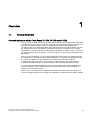
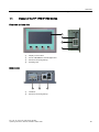
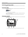
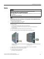
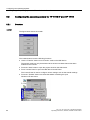
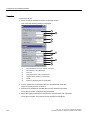
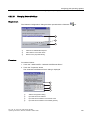
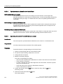
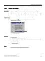
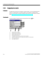
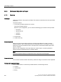
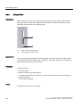
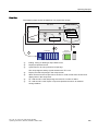
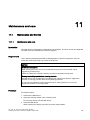
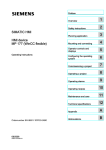
1.2 Design of the TP 177A HMI Device
1.2
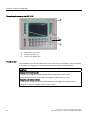
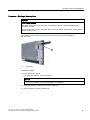
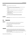
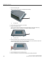
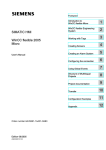
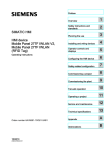
Design of the TP 177A HMI Device
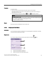
Front view and side view
①
Opening caused by design - not a slot for a memory card
②
Display / touch screen
③
Mounting seal
④
Mounting clamp recess
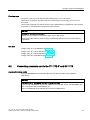
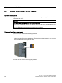
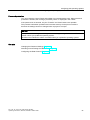
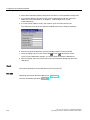
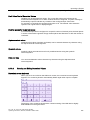
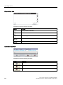
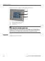
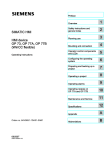
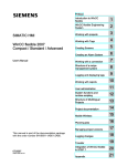
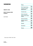
Bottom view
16
TP 177A, TP 177B, OP 177B (WinCC flexible)
Operating Instructions, 08/2008, 6AV6691-1DG01-0AB1
Overview
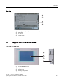
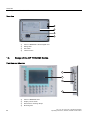
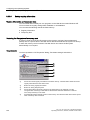
1.3 Design of the TP 177B 6" HMI device
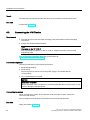
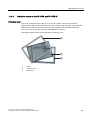
Rear view
1.3
①
Opening caused by design - not a slot for a memory card
②
Rating label
③
DIP switch
④
Interface name
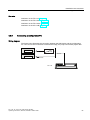
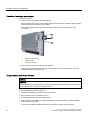
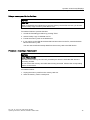
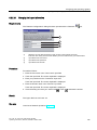
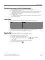
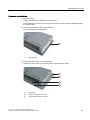
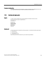
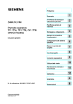
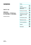
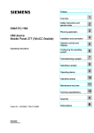
Design of the TP 177B 6" HMI device
Front view and side view
①
Slot for a MultiMedia card
②
Display / touch screen
③
Mounting seal
④
Mounting clamp recess
TP 177A, TP 177B, OP 177B (WinCC flexible)
Operating Instructions, 08/2008, 6AV6691-1DG01-0AB1
17
Overview
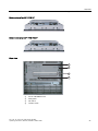
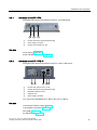
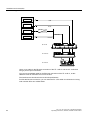
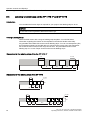
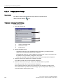
1.3 Design of the TP 177B 6" HMI device
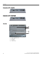
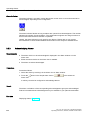
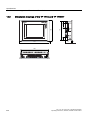
Bottom view of a TP 177B 6" DP
Bottom view of a TP 177B 6" PN/DP
Rear view
18
①
Slot for a MultiMedia card
②
Rating label
③
DIP switch
④
Interface name
TP 177A, TP 177B, OP 177B (WinCC flexible)
Operating Instructions, 08/2008, 6AV6691-1DG01-0AB1
Overview
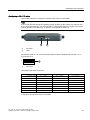
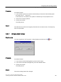
1.4 Design of the TP 177B 4" HMI device
1.4
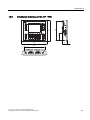
Design of the TP 177B 4" HMI device
Front view and side view
①
Display / touch screen
②
Slot for a MultiMedia / Secure Digital card
③
Recess for mounting clamps
④
Mounting seal
Bottom view
①
Interfaces
②
Recess for mounting clamps
TP 177A, TP 177B, OP 177B (WinCC flexible)
Operating Instructions, 08/2008, 6AV6691-1DG01-0AB1
19
Overview
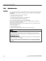
1.5 Design of the OP 177B HMI Device
Rear view
1.5
①
Slot for a MultiMedia / Secure Digital card
②
Rating label
③
DIP switch
④
Interface name
Design of the OP 177B HMI Device
Front view and side view
①
20
Slot for a MultiMedia card
②
Display / touch screen
③
Recesses for mounting clamps
④
Mounting seal
TP 177A, TP 177B, OP 177B (WinCC flexible)
Operating Instructions, 08/2008, 6AV6691-1DG01-0AB1
Overview
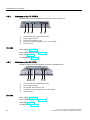
1.5 Design of the OP 177B HMI Device
Bottom view of an OP 177B DP
Bottom view of an OP 177B PN/DP
Rear view
①
Slot for a MultiMedia card
②
Rating label
③
DIP switch
④
Interface name
TP 177A, TP 177B, OP 177B (WinCC flexible)
Operating Instructions, 08/2008, 6AV6691-1DG01-0AB1
21
Overview
1.6 Accessories
1.6
Accessories
Accessory kit
The accessory kit contains the following:
● For the power supply: a plug-in terminal strip
● To install the TP 177A, TP 177B 6", and the OP 177B: Plastic mounting clamps
● For the installation of the TP 177B 4": Metal mounting clamps
Additional documents may be enclosed with the accessory kit.
1.7
Miscellaneous
RS 422 / RS 232 converter
The converter is required to connect a SIMATIC S5 controller and controllers from other
manufacturers. Connect the RS 422-RS 232 converter to the RS 422 / RS 485 interface.
The converter converts the input signals to RS-232 signals.
The converter is not part of the scope of delivery of the HMI device. The converter can be
ordered separately using order number 6AV6 671-8XE00-0AX0.
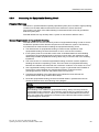
PC / PPI cable
You need the PC / PPI cable for TP 177A, TP 177B 6" and OP 177B to update the operating
system by resetting it to the factory settings. In addition, with TP 177B and OP 177B you can
use the cable for transferring purposes. Connect the PC/PPI cable to the RS 422/RS 485
interface. The cable converts the input signals to RS-232 signals.
The cable is not included the scope of delivery for the HMI device. The cable can be ordered
separately under the order number 6ES7 901-3CB30-0XA0.
Note
If the connection fails during the operating system update, set the system to a lower bit rate.
If you use a higher bit rate, you must use the PC / PPI cable release 3 or higher.
The version code is printed on the cable (e.g., "E stand 3" corresponds to version 3).
90° elbow adapter
If space is limited, e.g. to install the TP 177A in vertical format, you can use an elbow
adapter at the RS 422 / RS 485 interface.
The adapter is not part of the scope of delivery of the HMI device. The adapter can be
ordered separately with order number 6AV6 671-8XD00-0XA0.
22
TP 177A, TP 177B, OP 177B (WinCC flexible)
Operating Instructions, 08/2008, 6AV6691-1DG01-0AB1
Overview
1.8 Functional scope with WinCC flexible
PROFIBUS bus connector
We recommend using straight PROFIBUS bus connectors. The connectors are not included
in the scope of supply for the HMI device. The connectors can be ordered separately with
order number 6GK1 500-0FC10.
Memory card
Only use SD memory cards or MultiMediaCards tested and approved by Siemens AG for the
respective HMI device.
Protective foil
Protective foil is available for the HMI devices. Suitable protective foil can be ordered
separately under the following order numbers:
● TP 177A, TP 177B 6", OP 177B: Order number 6AV6 671-2XC00-0AX0
● TP 177B 4": Order number 6AV6 671-2EC00-0AX0
Protective cover set
A protective cover set can be ordered for the TP 177A and TP 177B 6" HMI devices with the
order number 6AV6 574-1AE00-4AX0.
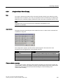
1.8
Functional scope with WinCC flexible
General
The following tables show the objects which can be integrated in a project for a TP 177A,
TP 177B and OP 177B.
Note
The specified values are maximum values for the respective objects. It is not possible to use
the maximum values for all objects because the available memory of the HMI device is
limited. For additional information on calculation of the system limits see the WinCC flexible
online help.
TP 177A, TP 177B, OP 177B (WinCC flexible)
Operating Instructions, 08/2008, 6AV6691-1DG01-0AB1
23
Overview
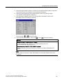
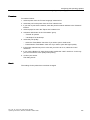
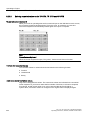
1.8 Functional scope with WinCC flexible
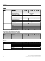
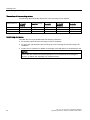
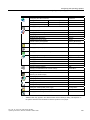
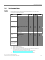
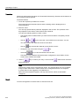
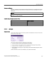
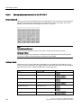
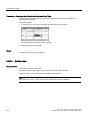
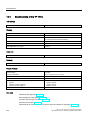
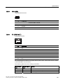
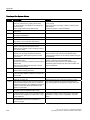
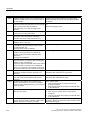
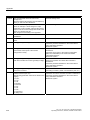
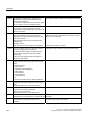
Alarms
Object
Specification
TP 177A
Alarm
Number of discrete alarms
1000
2000
Number of analog alarms
15
50
Length of the alarm text
Max. 8
Display
Alarm view,
Alarm window
Acknowledge single error alarms
Yes
Yes
Edit alarm
Memory characteristics
Yes
Volatile
Alarm buffer capacity
Non-volatile
256 alarms
Simultaneously queued alarm
events
Max. 64
View alarm
Yes
Delete alarm buffer
Print alarm line by line
16 acknowledgment groups
Yes
Alarm indicator
Alarm buffer
OP 177B
80 characters
Number of tags in an alarm
Acknowledge several error alarms
simultaneously
(group acknowledgement)
TP 177B
Yes
No
Yes
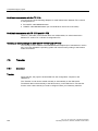
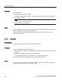
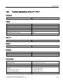
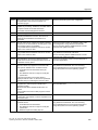
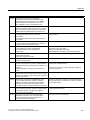
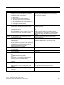
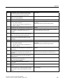
Tags, Values, Lists and Calculation Functions
Object
Specification
Tag
Number
TP 177A
TP 177B
500
OP 177B
1000
Limit monitoring
Input/Output
Yes
Linear scaling
Input/Output
Yes
Text List
Number
300
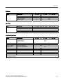
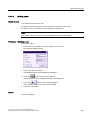
Screens
Object
Specification
Screen
Number
TP 177B
250
OP 177B
500
Fields per screen
30
50
Tags per screen
30
50
Complex objects per screen
(e.g. bars)
Template
24
TP 177A
5
Yes
TP 177A, TP 177B, OP 177B (WinCC flexible)
Operating Instructions, 08/2008, 6AV6691-1DG01-0AB1
Overview
1.8 Functional scope with WinCC flexible
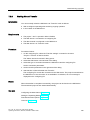
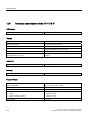
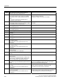
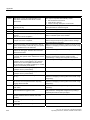
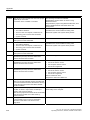
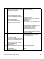
Recipes
Object
Specification
TP 177A
TP 177B
OP 177B
Recipe
Number
5
100
Data Records per Recipe
20
200
Entries per Recipe
20
200
Recipe screens
No
Yes
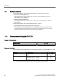
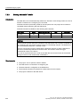
Info texts
Object
Specification
Infotext
Length (no. of characters)
TP 177A
TP 177B
320
For alarms
Yes
For screens
Yes
For screen objects (e.g. IO fields)
Yes
OP 177B
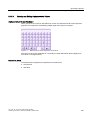
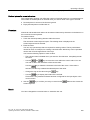
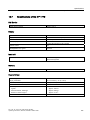
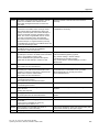
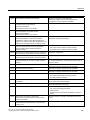
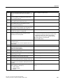
Additional functions
Object
Specification
TP 177A
Screen settings
Touch screen calibration
Yes
Contrast setting
Yes
1)
TP 177B
OP 177B
Yes
Brightness setting2)
Screen saver
-
Language change
Number of languages
Yes
Graphic object
Vector and pixel graphics
Trend views
Number
25
50
Trends per view
Number
4
8
5
16
Yes
Task Planner
Number of tasks
-
10
Text object
Number
1000
2500
Security
Number of Users
100
50
1) not with TP 177B 4"
2) not with TP 177B 4"
TP 177A, TP 177B, OP 177B (WinCC flexible)
Operating Instructions, 08/2008, 6AV6691-1DG01-0AB1
25
Overview
1.9 Software options
1.9
Software options
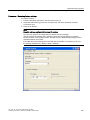
The following software options are available for the TP 177B and the OP 177B:
● WinCC Flexible/Sm@rtService
The Sm@rtService option enables you to access a remote HMI device from the
HMI device or PC via Ethernet.
● WinCC Flexible/Sm@rtAccess
The Sm@rtAccess option enables you to set up communication between different
HMI systems.
The following software options are available for the TP 177B 4":
● Uninterruptable Power Supply (UPS) with USB support
When interfacing an uninterruptible power supply, the HMI device is shut down in a
controlled manner after a buffer time in the event of a power failure. The TP 177B 4"
supports SITOP DC UPS modules connected via the USB port.
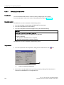
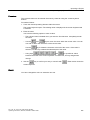
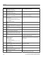
1.10
Communication Using the TP 177A
Number of Connections
Interconnection
TP 177A
Number with MPI/PROFIBUS DP
4 (on the same bus)
Siemens Controllers
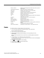
The following table shows the Siemens controllers and protocols or profiles that can be used.
Controller
Protocol/Profile
SIMATIC S7-200
PPI
yes
MPI 1)
yes
MPI
yes
PROFIBUS DP up to 1.5 Mbps
yes
PROFIBUS DP up to 12 Mbps
no
SIMATIC S7-300/400
1)
26
TP 177A
If you require a baud rate of 9.6 Kbps, use the "DP" profile in WinCC flexible
TP 177A, TP 177B, OP 177B (WinCC flexible)
Operating Instructions, 08/2008, 6AV6691-1DG01-0AB1
Overview
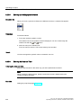
1.11 Communication Using the TP 177B and OP 177B
1.11
Communication Using the TP 177B and OP 177B
Number of Connections
Interconnection
TP 177B
Number using a point-to-point connection
OP 177B
1
Number using a bus connection
4 on the same bus
Siemens Controllers
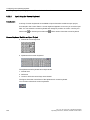
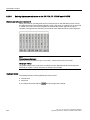
The following table shows the Siemens controllers and protocols or profiles that can be used.
Controller
Protocol/Profile
TP 177B 4"
PN/DP
TP 177B 6"
DP
TP 177B 6"
PN/DP
OP 177B
DP
OP 177B
PN/DP
SIMATIC
S7-300/400
MPI
Yes
Yes
Yes
Yes
Yes
PROFIBUS DP up to
12 Mbps
Yes
Yes
Yes
Yes
Yes
Yes
No
Yes
No
Yes
PROFINET
SIMATIC S5
PROFIBUS DP up to
12 Mbps
Yes
Yes
Yes
Yes
Yes
SIMATIC S7-200
PPI
Yes
Yes
Yes
Yes
Yes
MPI
Yes
Yes
Yes
Yes
Yes
PROFIBUS DP CPU 215
Yes
Yes
Yes
Yes
Yes
PROFIBUS DP standard
Yes
Yes
Yes
Yes
Yes
Yes
Yes
Yes
Yes
SIMATIC 500/505 NITP
Yes
PROFIBUS DP up to
12 Mbps
1)
1)
Yes
Yes
1)
Yes
Yes
1)
Yes
PROFINET IO must be locked.
TP 177A, TP 177B, OP 177B (WinCC flexible)
Operating Instructions, 08/2008, 6AV6691-1DG01-0AB1
27
Overview
1.11 Communication Using the TP 177B and OP 177B
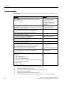
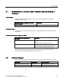
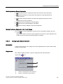
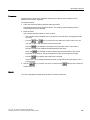
Third-party controllers
The following table shows controllers of other manufacturers and protocols or profiles that
can be used.
Controller
Protocol
Allen-Bradley
PLC series SLC500, SLC501, SLC502, SLC503, SLC504,
SLC505, MicroLogix
•
•
•
•
DF1 1) 3) 4) 6)
DH+ via DF1 gateway
(KF2 module) 2) 3) 4) 6)
DH485 via DF1 gateway
(via KF3 module)3) 4) 6)
DH485
Allen Bradley
PLC series PLC 5/11, PLC5/20, PLC 5/30, PLC 5/40, PLC 5/40L,
PLC 5/60, PLC 5/60L, PLC 5/80
•
•
DF1 4) 6)
DH+ via DF1 gateway
(KF2 module) 3) 4) 6)
Allen Bradley
•
Ethernet/IP 5)
PLC series ControlLogix 5500 (with 1756-ENBT) and
CompactLogix 5300 (1769-L32E and 1769-L35E)
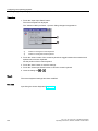
GE Fanuc Automation
PLC series 90-30, 90-70, 90-Micro
SNP 4) 6)
LG Industrial Systems (Lucky Goldstar)/IMO
PLC series GLOFA-GM/G4, G6, G7M
Dedicated communication 4) 6)
Mitsubishi Electric
PLC series MELSEC FX, MELSEC FX0
FX (Mitsubishi PG) 4) 6)
Mitsubishi Melsec
PLC series FX, A, Ans, Q, QnAS
Protocol 4 4) 6)
Modicon (Schneider Automation)
•
Modbus RTU 3) 4) 6)
PLC series Compact and 984 via Ethernet bridge
•
Modbus TCP/IP (Ethernet) 5)
OMRON
PLC series SYSMAC C, SYSMAC CV, SYSMAC CS1,
SYSMAC alpha, CP
Hostlink/Multilink
(SYSMAC Way) 4) 6)
Telemecanique
Uni-Telway 4) 6)
PLC series Modicon 984, TSX Quantum and TSX Compact
PLC series Quantum, Momentum, Premium und Micro
PLC series:
• TSX 7 with P47 411
• TSX 7 with P47/67/87/107 420
• TSX 7 with P47/67/87/107 425
• Module TSX SCM 21.6 with the aforementioned TSX 7 CPUs
• TSX 17 with module SCG 1161
• TSX 37 (Micro)
• TSX 57 (Premium)
28
1)
Applies to controllers SLC503, SLC504, SLC505, MicroLogix
2)
Applies to controllers SLC504, via DF1.
3)
Only with converter RS 422-RS 232 6AV6 671-8XE00-0AX0 (Option)
4)
PROFINET IO must be locked.
5)
Not approved for TP 177B 6" DP or OP 177B DP
6)
Deactivate the "Remote Control" check box under "Channel 1" in the "Transfer Settings".
TP 177A, TP 177B, OP 177B (WinCC flexible)
Operating Instructions, 08/2008, 6AV6691-1DG01-0AB1
Safety Instructions and General Notes
2.1 Safety Information
Safety Instructions and General Notes
2.1
2
Safety Information
Working on the cabinet
WARNING
Open equipment
The HMI device is an open equipment. This means that the HMI device may only be
installed in cubicles or cabinets, whereby the device can be operated from the front panel.
Access to the cubicle or cabinet in which the HMI device is installed should only be possible
by means of a key or tool and for personnel who have received instruction or are
authorized.
Danger, high voltage
Opening the cabinet will expose high voltage parts. Contact with these parts could be fatal.
Switch off the power supply to the cabinet before opening it.
Hazardous areas
When operating the HMI device in hazardous areas the following warning applies.
WARNING
Explosion Hazard
Do not disconnect while circuit is live unless area is known to be non-hazardous.
Substitution of components may impair suitability for Class I, Division 2 or Zone 2.
High frequency radiation
NOTICE
Unintentional operating situations
High frequency radiation, from mobile phones for example, can cause unintentional
operating situations.
TP 177A, TP 177B, OP 177B (WinCC flexible)
Operating Instructions, 08/2008, 6AV6691-1DG01-0AB1
29
Safety Instructions and General Notes
2.2 Standards and Approvals
2.2
Standards and Approvals
Valid certifications
CAUTION
Valid certifications
The overview below provides information on available certifications.
The HMI device itself is certified as shown on the label on its rear panel.
CE Certification
The automation system meets the general and safety-related requirements of the following
EC directives and conforms to the harmonized European standards (EN) for programmable
logic controllers published in the official gazettes of the European Union:
● 2004/108/EC "Electromagnetic Compatibility" (EMC Directive)
● 94/9/EC "Equipment and Protective Systems Intended for Use in Potentially Explosive
Atmospheres" (Explosion Protection Directive)
EC Declaration of Conformity
The EC Declarations of Conformity are available to the relevant authorities at the following
address:
Siemens Aktiengesellschaft
Industry Sector
I IA AS RD ST PLC
P.O. Box 1963
D-92209 Amberg
30
TP 177A, TP 177B, OP 177B (WinCC flexible)
Operating Instructions, 08/2008, 6AV6691-1DG01-0AB1
Safety Instructions and General Notes
2.2 Standards and Approvals
UL approval
Underwriters Laboratories Inc. conforming to
● UL 508 (Industrial Control Equipment)
● CSA C22.2 No. 142, (Process Control Equipment)
or
Underwriters Laboratories Inc. conforming to
● UL 508 (Industrial Control Equipment)
● CSA C22.2 No. 142, (Process Control Equipment)
● UL 1604 (Hazardous Location)
● CSA-213 (Hazardous Location)
Approved for use in
● Class I, Division 2, Group A, B, C, D or
● Class I, Zone 2, Group IIC or
● non-hazardous locations
FM Approval
FM
APPROVED
Factory Mutual Research (FM) conforming to
● Approval Standard Class Number 3611, 3600, 3810
Approved for use in
● Class I, Division 2, Group A, B, C, D T4
● Class I, Zone 2, Group IIC T4
TP 177A, TP 177B, OP 177B (WinCC flexible)
Operating Instructions, 08/2008, 6AV6691-1DG01-0AB1
31
Safety Instructions and General Notes
2.2 Standards and Approvals
Ex Certification
The following certifications apply to the HMI device in accordance with
● EN 60079-0:2006
● EN 60079-15:2005
● EN 61241-1:2004
● IEC 61241-0:2004+Cor.2005
valid:
II 3 G
Ex nA II Tx
II 3 D
Ex tD A22 IP6X T xx °C
x ... Temperature values, see EU design examination certificate
The EU design examination certificates are available on the Internet at
"http://support.automation.siemens.com".
The table below describes the test numbers of the HMI device classes.
Manufacturer site
HMI device class
Test number
Siemens AG
Industry Sector
Werner-von-Siemens-Strasse 50
D92224 Amberg
Germany
177
KEMA 04ATEX1297X
Label for Australia
N117
The HMI device fulfills the requirements of standard AS/NZS 2064 (Class A).
IEC 61131
The HMI device fulfills the requirements and criteria conforming to IEC 61131-2,
Programmable Logic PLCs, Part 2: Operating resource requirements and tests.
32
TP 177A, TP 177B, OP 177B (WinCC flexible)
Operating Instructions, 08/2008, 6AV6691-1DG01-0AB1
Safety Instructions and General Notes
2.3 Notes about Usage
2.3
Notes about Usage
Use in Industrial Environments
The HMI device is designed for industrial use. It conforms to the following standards:
● Requirements for unintentional emissions EN 61000-6-4: 2007
● Requirements for interference immunity DIN EN 61000-6-2:2005
Use in Residential Areas
Note
The HMI device is not suitable for use in residential areas. If you use the HMI device in
residential areas, the radio/TV reception may be impeded.
If the HMI device is used in residential areas, you must take measures to achieve limit
class B conforming to EN 55011 for RF interference.
A suitable measure for achieving the required RF interference level for limit class B includes
for example:
● Use of filters in electrical supply lines
Individual acceptance is required.
Use in Potentially Explosive Atmosphere, Zones 2 and 22.
CAUTION
The following overview shows possible certifications.
The HMI device itself is certified as shown on the label on its rear panel.
DANGER
Explosion hazard
Operate the HMI device in a potentially explosive zone 2 atmosphere only if it has been
approved and certified for such environments.
WARNING
Personal Injury and Property Damage Can Occur
Personal injury and property damage can occur in potentially explosive atmospheres if an
electric plug is disconnected from the HMI device while the system is in operation.
In potentially explosive atmospheres, always turn off power to the HMI device before
disconnecting any connectors.
TP 177A, TP 177B, OP 177B (WinCC flexible)
Operating Instructions, 08/2008, 6AV6691-1DG01-0AB1
33
Safety Instructions and General Notes
2.3 Notes about Usage
Potentially Explosive Atmospheres Zones 2 and 22
Potentially explosive atmospheres are classified by zones. The zones are classified
according to the probability of the presence of an explosive atmosphere.
Zone
Explosion hazard
Example
2
Explosive gas atmospheres occur Areas around flanged pipe joints with flat
seldom and briefly
gaskets in closed rooms
22
Explosive dust atmospheres
occur seldom and briefly
-
Safe zone
No
•
•
•
Outside zone 2
Outside zone 22
Standard applications for distributed IO
Approval
The following certifications apply to the HMI device in accordance with
● EN 60079-0:2006
● EN 60079-15:2005
● EN 61241-1:2004
● IEC 61241-0:2004+Cor.2005
valid:
II 3 G
Ex nA II Tx
II 3 D
Ex tD A22 IP6X T xx °C
x ... Temperature values, see EU design examination certificate
The EU design examination certificates are available on the Internet at
"http://support.automation.siemens.com".
The table below describes the test numbers of the HMI device classes.
34
Manufacturer site
HMI device class
Test number
Siemens AG
Industry Sector
Werner-von-Siemens-Strasse 50
D92224 Amberg
Germany
177
KEMA 04ATEX1297X
TP 177A, TP 177B, OP 177B (WinCC flexible)
Operating Instructions, 08/2008, 6AV6691-1DG01-0AB1
Safety Instructions and General Notes
2.3 Notes about Usage
Operating conditions for Zones 2 and 22
● The HMI device must be installed in some form of enclosure. In accordance with
EN 60529, the enclosure must guarantee the following:
– Protection type IP54 or higher for zone 2
– Protection type IP5x or higher for zone 22
Installation must ensure that at least IP65 degree of protection is given
(according to EN 60529).
Make allowances for the ambient conditions under which you install the HMI device.
A manufacturer declaration must be provided for the enclosure in accordance with
EC directive 94/9, stating that it is fit for purpose.
Follow the operating instructions to ensure that the protection type on the front panel
is guaranteed.
● The ambient temperature range is 0 °C ≤ T ≤ 50 °C. Under these conditions, the
HMI device will satisfy temperature class Tx for category 3G and support a maximum
surface temperature of xx °C for category 3D. (x ... temperature values, see design
examination certificate).
Refer to the operating instructions for details of limitations resulting from the ambient
temperature range.
● In situations where the temperature on the cable at the cable inlet of this enclosure
exceeds 70 °C, or where the temperature on the wire branching point exceeds 80 °C
under operating conditions, the temperature specifications of the cables must match the
actually measured temperatures.
● Put measures in place to ensure the rated voltage is not exceeded.
Any transient interference voltages above the rated value must not exceed 40 %.
● The HMI device should be protected from mechanical loads > 4 J or > 2 J in the region of
the display.
● Ensure that the atmosphere is not explosive during servicing.
Measures that impair or remove the protection type of the HMI device are not permitted
while the system is in operation.
● If the HMI device was dismantled, check the mounting seal for damage before
reassembling the HMI device. A damaged, porous or used mounting seal no longer
meets the requirements of the protection type. In this case, the mounting seal must be
replaced.
● Turn the HMI device off if any cracks appear in the front coating, holes are damaged or
the front coating starts to peel off.
Exchange the HMI device. Restart the system again after the device has been
exchanged.
TP 177A, TP 177B, OP 177B (WinCC flexible)
Operating Instructions, 08/2008, 6AV6691-1DG01-0AB1
35
Safety Instructions and General Notes
2.4 Electromagnetic Compatibility
Repairs
The HMI device is maintenance-free. In case of repair, the HMI device must be shipped to
the Return Center in Fürth. The HMI device may only be repaired there. The address is:
Siemens AG
Industry Sector
Returns Center
Siemensstrasse 2
90766 Fürth
Germany
Additional Information
Please also observe the product information "Use in potentially explosive atmospheres,
zones 2 and 22."
The product information is located on the mini CD that is enclosed with the HMI device
upon delivery.
Approval
Note
HMI devices with approval to II 3G Ex nA II T4 may only be used on SIMATIC systems of
device category 3.
2.4
Electromagnetic Compatibility
Introduction
The HMI device fulfills requirements of the EMC directive of the domestic European market
and other requirements.
EMC-compliant mounting of HMI devices
EMC-compliant mounting of the HMI device and the use of interference-proof cables will
ensure trouble-free operation. The "Directives for Interference-free installation of PLCs" and
the "PROFIBUS Networks" manual also apply for the installation of the HMI device.
36
TP 177A, TP 177B, OP 177B (WinCC flexible)
Operating Instructions, 08/2008, 6AV6691-1DG01-0AB1
Safety Instructions and General Notes
2.4 Electromagnetic Compatibility
Pulse-shaped Interference
The following table shows the EMC properties of the modules with respect to pulse-shaped
interference. The HMI device must fulfill the specifications and directives relating to electrical
installation as a basic prerequisite.
Pulse-shaped
interference
Tested with
Corresponds to test
intensity
Electrostatic discharge
conforming to
IEC 61000-4-2
Air discharge: 8 kV
Contact discharge: 6 kV
3
Burst pulses
(high-speed transient
interference)
conforming to
IEC 61000-4-4
2 KV power cable
2 KV signal cable, > 30 m
1 KV signal cable, < 30 m
3
High-power surge pulses conforming to IEC 61000-4-5, external protective circuit required
(refer to the manual, Programmable Controller S7-300, Installation,
chapter "Lightning and Overvoltage Protection").
•
Asymmetric coupling
2 kV power cable
DC voltage with protective elements
3
2 KV signal/data cable, > 30 m,
with protective elements as required
•
Asymmetric coupling
1 kV power cable
DC voltage with protective elements
3
1 KV signal cable, > 30 m,
with protective elements as required
Sinusoidal Interferences
The table below shows the EMC properties of the modules as they relate to sinusoidal
interference. The HMI device must fulfill the specifications and directives relating to electrical
installation as a basic prerequisite.
Sinusoidal interference
RF interference
(electromagnetic fields)
• Conforming to
IEC 61000-4-3
•
Conforming to
IEC 61000-4-3
Test values
Corresponds to test
intensity
3
80% amplitude modulation at 1 kHz
with 10 V/m in the range of 80 MHz to 1 GHz
with 3 V/m in the range 1.4 GHz to 2 GHz
with 1 V/m the range 2 GHz to 2.7 GHz
10 V/m with 50% pulse modulation at 900 MHz
10 V/m with 50% pulse modulation at 1.89 GHz
RF interference current
on cables and cable
shielding conforming to
IEC 61000-4-6
Test voltage 10 V, with 80% amplitude modulation
of 1 kHz in the 10 MHz to 80 MHz range
TP 177A, TP 177B, OP 177B (WinCC flexible)
Operating Instructions, 08/2008, 6AV6691-1DG01-0AB1
3
37
Safety Instructions and General Notes
2.5 Transport and Storage Conditions
Emission of Radio Interference
Emission of electromagnetic interference conforming to 55011,
Limit value class A, Group 1, measured at a distance of 10 m:
From 30 to 230 MHz
< 40 dB (V/m) quasi-peak
From 230 to 1000 MHz
< 47 dB (V/m) quasi-peak
Additional Measures
Before you connect an HMI device to the public electricity supply, ensure that it is compliant
with Limit Class B conforming to 55022.
2.5
Transport and Storage Conditions
Mechanical and Climatic Transport and Storage Conditions
The transport and storage conditions of this HMI device exceed requirements conforming to
IEC 61131-2. The following specifications apply to the transport and storage of an
HMI device in its original packing.
The climatic conditions comply to the following standards:
● IEC 60721-3-3, Class 3K7 for storage
● IEC 60721-3-2, Class 2K4 for transport
The mechanical requirements are compliant with EC 60721-3-2, Class 2M2.
Type of Condition
Permissible range
Drop test (in transport package)
≤1m
Temperature
from –20 to +60° C
Air pressure
from 1080 to 660 hPa,
corresponds to an elevation of -1000 to 3500 m
Relative humidity
from 10 to 90% without condensation
Sinusoidal vibration conforming to
IEC 60068-2-6
5 to 8.4 Hz: 3.5 mm
8.4 Hz to 150 Hz: 9.8 m/s2
Shock conforming to IEC 60068-2-29
250 m/s2, 6 ms, 1000 shocks
NOTICE
Ensure that no condensation (dewing) develops on or inside the HMI device after
transporting it at low temperatures or after it has been exposed to extreme temperature
fluctuations.
The HMI device must have acquired room temperature before it is put into operation.
Do not expose the HMI device to direct radiation from a heater in order to warm it up.
If dewing has developed, wait approximately four hours until the HMI device has dried
completely before switching it on.
Prerequisite for the trouble-free and safe operation of the HMI device is proper transport and
storage, installation and assembly and careful operation and maintenance.
Warranty for the HMI device is deemed void if these specifications are ignored.
38
TP 177A, TP 177B, OP 177B (WinCC flexible)
Operating Instructions, 08/2008, 6AV6691-1DG01-0AB1
3
Planning Use
3.1
Mounting Information
Mechanical and Climatic Conditions of Use
The HMI device is intended for installation in weatherproof permanent locations.
The conditions of use are compliant with requirements to DIN IEC 60721-3-3:
● Class 3M3 (mechanical requirements)
● Class 3K3 (climatic requirements)
Use with Additional Measures
Examples of applications where the use of the HMI device requires additional measures:
● In locations with a high degree of ionizing radiation
● In locations with extreme operating conditions resulting from situations such as
the following:
– Corrosive vapors, gases, oils or chemicals
– Electrical or magnetic fields of high intensity
● In plants requiring special monitoring features, for example:
– Elevator systems
– Systems in especially hazardous rooms
Mechanical ambient conditions
The mechanical ambient conditions for the HMI device are specified in the following table in
terms of sinusoidal vibration.
Frequency range
in Hz
Constant
10 ≤ f ≤ 58
Amplitude 0.0375 mm
Amplitude 0.075 mm
58 ≤ f ≤ 150
Constant acceleration 0.5 g
Constant acceleration 1 g
TP 177A, TP 177B, OP 177B (WinCC flexible)
Operating Instructions, 08/2008, 6AV6691-1DG01-0AB1
Intermittent
39
Planning Use
3.1 Mounting Information
Reduction of Vibration
If the HMI device is subjected to greater shocks or vibrations, you must take appropriate
measures to reduce acceleration or amplitudes.
We recommend fitting the HMI device to vibration-absorbent material (on metal shock
absorbers, for example).
Testing for Mechanical Ambient Conditions
The following table provides information on the type and scope of tests for mechanical
ambient conditions.
The check
includes
Test standard
Comments
Vibrations
Vibration test conforming to
IEC 60068, part 2–6
(sinusoidal)
Type of vibration:
Transitional rate of the frequency:
1 octave/minute.
10 ≤ f ≤ 58,
Constant amplitude 0.075 mm
58 ≤ f ≤ 150,
Constant acceleration 1 g
Vibration duration:
10 frequency cycles per axis in each of the
three axes vertical to each other
Shock
Shock testing in accordance
with IEC 60068, Part 2 –29
Type of shock: half sine
Shock intensity:
Peak value 15 g, duration 11 ms
Direction of impact:
3 shocks in ± direction of axis in each of the
three axes vertical to each other
Climatic ambient conditions
The HMI device may be used under the following climatic ambient conditions:
40
Ambient conditions
Permissible range
Comments
Temperature
• Vertical installation
• Inclined mounting
0 to 50° C
See the "Mounting positions and type
of fixation" section
Relative humidity
10 to 90%
Without condensation, corresponds to
a relative humidity, stress class 2
conforming to IEC 61131, part 2
Air pressure
1080 to 795 hPa
Corresponds to an elevation of
-1000 to 2000 m
Pollutant concentration
SO2: < 0.5 vpm;
Relative humidity < 60 %,
no condensation
Check: 10 vpm; 4 days
H2S: < 0.1 vpm;
relative humidity < 60 %,
no condensation
Check: 1 vpm; 4 days
0 to 40° C
TP 177A, TP 177B, OP 177B (WinCC flexible)
Operating Instructions, 08/2008, 6AV6691-1DG01-0AB1
Planning Use
3.2 Mounting Positions and Fixation
3.2
Mounting Positions and Fixation
Mounting position
The HMI device is designed for mounting in racks, cabinets, control boards and consoles.
In the following, all of these mounting options are referred to by the general term "cabinet".
The HMI device is self-ventilated and approved for vertical and inclined mounting in
stationary cabinets.
–
①
+
Mounting position
Deviation from the vertical
Inclined
≤ –35°
②
Vertical
0°
③
Inclined
≤ 35°
CAUTION
Impermissible ambient temperatures
Do not operate the HMI device without auxiliary ventilation if the maximum permissible
ambient temperature is exceeded. The HMI device may otherwise get damaged and its
certifications and warranty will be void.
TP 177A, TP 177B, OP 177B (WinCC flexible)
Operating Instructions, 08/2008, 6AV6691-1DG01-0AB1
41
Planning Use
3.2 Mounting Positions and Fixation
Horizontal mounting for TP 177A, TP 177B and OP 177B
When mounted horizontally, the cable inlets are located at the bottom.
Vertical mounting for TP 177A
When mounted vertically, the cable inlets are located on the right.
Securing the TP 177A, TP 177B 6" and OP 177B
Plastic mounting clamps are provided for mounting the device. The mounting clamps
hook into recesses on the HMI device. The overall HMI device dimensions are not
exceeded by this.
42
①
Hook
②
Cross-tip screw
TP 177A, TP 177B, OP 177B (WinCC flexible)
Operating Instructions, 08/2008, 6AV6691-1DG01-0AB1
Planning Use
3.3 Preparing for Mounting
Securing the TP 177B 4"
Metal mounting clamps are provided for mounting. The mounting clamps hook into recesses
on the HMI device. The overall HMI device dimensions are not exceeded by this.
3.3
①
Threaded stud
②
Hook
Preparing for Mounting
Select the mounting location of the HMI device
Points to observe when selecting the mounting location:
● Position the HMI device so that it is not subjected to direct sunlight.
● Position the HMI device such that it is ergonomically accessible for the user. Choose a
suitable mounting height.
● Ensure that the air vents of the HMI device are not covered as a result of the mounting.
● Observe the permissible mounting positions for the HMI device.
Degrees of protection
The degrees of protection are only guaranteed when the following is observed for the
mounting cut-out:
● Material thickness at the mounting cut-out for IP65 degree of protection:
2 to 6 mm
● Material thickness at the mounting cut-out for NEMA 4X/NEMA 12 degree of protection
(indoor use only):
3 mm to 6 mm
● Permitted deviation from plane at the mounting cut-out: ≤ 0.5 mm
This condition must be fulfilled for the mounted HMI device.
● Permissible surface roughness in the area of the seal: ≤ 120 µm (Rz 120)
TP 177A, TP 177B, OP 177B (WinCC flexible)
Operating Instructions, 08/2008, 6AV6691-1DG01-0AB1
43
Planning Use
3.3 Preparing for Mounting
Dimensions of the mounting cut-out
The following table shows the dimensions of the mounting cut-out required.
Mounting cut-out
TP 177A
horizontal
mounting
TP 177A vertical
mounting
TP 177B 6"
Horizontal
TP 177B 4"
horizontal
mounting
OP 177B
Horizontal
Width
198+1 mm
142+1 mm
198+1 mm
123+1 mm
228+1 mm
Height
142+1
198+1
142+1
99+1
196+1 mm
Depth
50 mm
mm
mm
50 mm
mm
50 mm
mm
50 mm
55 mm
Maintaining clearances
The HMI device must be installed with the following clearances:
● 50 mm above and below the mounting cut-out for ventilation
● 15 mm to the right and left of the mounting cut-out for inserting the mounting clamps for
installation
● At least 10 mm clearance in addition to the depth of the HMI device is required at the rear
NOTICE
Ensure that the maximum ambient temperature is not exceeded when mounting the
device in a cabinet and especially in a closed enclosure.
44
TP 177A, TP 177B, OP 177B (WinCC flexible)
Operating Instructions, 08/2008, 6AV6691-1DG01-0AB1
Planning Use
3.4 Specifications for Insulation Tests, Protection Class and Degree of Protection
3.4
Specifications for Insulation Tests, Protection Class and Degree of
Protection
Test Coltages
Insulation resistance is demonstrated in the type test with the following test voltages
conforming to IEC 61131-2:
Circuits with a nominal voltage of Ue to other
circuits or ground
Test voltage
< 50 V
500 V DC
Protection Class
Protection Class I conforming to IEC 60536, i.e. equipotential bonding conductor to profile
rail required!
Protection from foreign objects and water
Degree of protection conforming to
IEC 60529
Explanation
Front
When mounted:
• IP65
• NEMA 4X/NEMA 12 (indoor use only)
Rear
IP20
Protection against touch with standard test fingers.
There is no protection against ingress by water.
The degree of protection provided by the front side can only be guaranteed when the
mounting seal lies completely against the mounting cut-out.
3.5
Nominal Voltages
The following table details the allowed rated line voltages and associated tolerance ranges.
HMI device
Rated voltage
Tolerance range
TP 177A, TP 177B 6", OP 177B
+24 VDC
20.4 to 28.8 V (–15%, +20%)
TP 177B 4"
+24 VDC
19.2 to 28.8 V (–20 %, +20 %)
TP 177A, TP 177B, OP 177B (WinCC flexible)
Operating Instructions, 08/2008, 6AV6691-1DG01-0AB1
45
Planning Use
3.5 Nominal Voltages
46
TP 177A, TP 177B, OP 177B (WinCC flexible)
Operating Instructions, 08/2008, 6AV6691-1DG01-0AB1
Installation and connection
4.1
4
Checking the package contents
Check the package contents for visible signs of transport damage and for completeness.
NOTICE
Damaged parts
Do not install parts damaged during shipment. In the case of damaged parts, contact your
Siemens representative.
The following is contained in the delivery:
● HMI device
● Accessory kit
The accessory kit contains the following:
– 1 terminal block for the power supply
– Mounting clamps for mounting the HMI device
Additional documents may be enclosed with the accessory kit.
Keep the supplied documentation in a safe place. The documentation belongs to the
HMI device and is required for subsequent commissioning.
4.2
Mounting the HMI Device
Requirement
All packaging components and protective foils should be removed from the HMI device.
You need the mounting clamps from the accessories kit for the installation. The mounting
seal must be available on the HMI device. If the mounting seal is damaged, order a
replacement seal. The mounting seal is part of the associated service pack.
Note
Plastic mounting clamps are enclosed in the TP 177A, TP 177B 6" and the OP177B.
Metal mounting clamps are included with the TP 177B 4".
TP 177A, TP 177B, OP 177B (WinCC flexible)
Operating Instructions, 08/2008, 6AV6691-1DG01-0AB1
47
Installation and connection
4.2 Mounting the HMI Device
Mounting clamps on the TP 177A and TP 177B 6"
Use a plastic mounting clamp on each side of the HMI device to secure it in the mounting
cut-out.
Mounting clamps TP 177B 4"
The recesses required to suspend the metal mounting clamps are marked with an arrow on
the back of the HMI device.
①
Marking for position of a mounting clamp
To ensure one of the degrees of protection IP65 or NEMA 4, suspend the metal mounting
clamps in the marked recesses.
In each case use one metal mounting for the right, left and bottom, and two at the top.
Mounting clamps on the OP 177B
If IP65 or NEMA 4 degrees of protection are required for the OP 177B, the mounting clamps
must be installed as follows.
①
48
Additionally required plastic mounting clamps for IP65 and NEMA 4 degrees of protection
TP 177A, TP 177B, OP 177B (WinCC flexible)
Operating Instructions, 08/2008, 6AV6691-1DG01-0AB1
Installation and connection
4.2 Mounting the HMI Device
Mounting
NOTICE
Always mount the HMI device according to the instructions in this manual.
Risk of guaranteed level of protection not being met
If the mounting seal is damaged or protrudes beyond the HMI device, the level of protection
is not ensured.
Check the fit of the mounting seal.
Note
Tighten the set screw or the cross-tip screw of the mounting clamps until the HMI device is
flush with the surface of the control cabinet. As an alternative, you can tighten the mounting
clamps using the following torque:
• Plastic mounting clamps: max. 0.15 Nm
• Metal mounting clamps: max. 0.2 Nm
Proceed as follows:
1. Check that the mounting seal is fitted on the HMI device.
Do not install the mounting seal turned inside out. This may cause leaks in the
mounting cut-out.
2. Insert the HMI device into the mounting cut-out from the front.
3. Insert a mounting clamp into the intended recesses on the HMI device.
Example: Inserting plastic mounting clamps Example: Inserting metal mounting clamps
on the TP 177A
on the TP 177 4"
4. Tighten the mounting clamp using a threaded stud or a cross-tip screwdriver.
5. Repeat steps 3 and 4 for all mounting clamps.
6. Check the fit of the mounting seal.
If necessary, repeat steps 1 to 6.
TP 177A, TP 177B, OP 177B (WinCC flexible)
Operating Instructions, 08/2008, 6AV6691-1DG01-0AB1
49
Installation and connection
4.3 Connecting the HMI Device
Result
The HMI device is mounted and the relevant level of protection is ensured at the front.
See also
Accessories (Page 22)
4.3
Connecting the HMI Device
Requirement
● The HMI device must be mounted according to the specifications of these operating
instructions.
● Always use standard shielded cables.
Note
Connector on the TP 177B 4"
Use only straight connectors on the TP 177B 4". Angled connectors could conceal
neighboring ports.
You can find more information about this on the Internet at
"http://mall.automation.siemens.com".
Connection sequence
Connect the HMI device in the following sequence:
1. Equipotential bonding
2. Power supply
Perform a power-up test to ensure the power supply is connected with the
correct polarity.
3. PLC / configuring PC if needed
NOTICE
Connection sequence
Always follow the correct sequence for connecting the HMI device. Failure to do so may
result in damage to the HMI device.
Connecting the cables
When connecting the cables, ensure that the contact pins are not bent. Secure the
connectors with screws.
The pin assignment of the ports is described in the technical specifications.
See also
Safety Information (Page 29)
50
TP 177A, TP 177B, OP 177B (WinCC flexible)
Operating Instructions, 08/2008, 6AV6691-1DG01-0AB1
Installation and connection
4.3 Connecting the HMI Device
4.3.1
Interfaces on the TP 177A
The figure below shows the interfaces of the TP 177A HMI device.
①
Chassis terminal for equipotential bonding
②
Power supply connector
③
RS 422 / 485 interface (IF 1B)
See also
Power Supply (Page 332)
X10/IF 1B (RS 422/RS 485) (Page 332)
4.3.2
Interfaces on the TP 177B 4"
The figure below shows the interfaces of the TP 177B 4" HMI device.
①
RS 422 / RS 485 port X10 / IF 1B
②
Chassis terminal for equipotential bonding
③
PROFINET interface X1 P1
④
USB port X20
⑤
Power supply connector
You connect the PROFIBUS DP or MPI to the X10 / IF 1B port.
See also
Connecting the Power Supply (Page 55)
Connecting the Controller (Page 58)
X20 (USB) (Page 333)
X1 (PROFINET) (Page 333)
TP 177A, TP 177B, OP 177B (WinCC flexible)
Operating Instructions, 08/2008, 6AV6691-1DG01-0AB1
51
Installation and connection
4.3 Connecting the HMI Device
4.3.3
Interfaces on the TP 177B 6"
The figure below shows the interfaces of the TP 177B 6" HMI device.
①
Chassis terminal for equipotential bonding
②
Power supply connector
③
RS 422 / 485 interface (IF 1B)
④
PROFINET connection (applies to TP 177B 6" PN/DP)
⑤
USB connection
See also
Power Supply (Page 332)
X10/IF 1B (RS 422/RS 485) (Page 332)
X20 (USB) (Page 333)
X1 (PROFINET) (Page 333)
4.3.4
Interfaces on the OP 177B
The figure below shows the interfaces of the OP 177B HMI device.
①
Chassis terminal for equipotential bonding
②
Power supply connector
③
RS -485/RS -422 interface (IF 1B)
④
PROFINET connection (applies to OP 177B PN/DP)
⑤
USB connection
See also
Power Supply (Page 332)
X10/IF 1B (RS 422/RS 485) (Page 332)
X20 (USB) (Page 333)
X1 (PROFINET) (Page 333)
52
TP 177A, TP 177B, OP 177B (WinCC flexible)
Operating Instructions, 08/2008, 6AV6691-1DG01-0AB1
Installation and connection
4.3 Connecting the HMI Device
4.3.5
Connecting the Equipotential Bonding Circuit
Potential Differences
Differences in potential between spatially separated system parts can lead to high equalizing
currents over the data cables and therefore to the destruction of their interfaces.
This situation may arise if the cable shielding is terminated at both ends and grounded at
different system parts.
Potential differences may develop when a system is connected to different mains.
General Requirements for Equipotential Bonding
Potential differences must be reduced by means of equipotential bonding in order to ensure
trouble-free operation of the relevant components of the electronic system. The following
must therefore be observed when installing the equipotential bonding circuit:
● The effectiveness of equipotential bonding increases as the impedance of the
equipotential bonding conductor decreases or as its cross-section increases.
● If two system parts are connected to each other via shielded data lines with shielding
connected to the grounding/protective conductor on both sides, the impedance of the
additionally installed equipotential bonding cables may not exceed 10% of the shielding
impedance.
● The cross-section of a selected equipotential bonding conductor must be capable of
handling the maximum equalizing current. The best results for equipotential bonding
between two cabinets were achieved with a minimum conductor cross-section of 16 mm2.
● Use equipotential bonding conductors made of copper or galvanized steel. Establish a
large-surface contact between the equipotential bonding conductors and the
grounding/protective conductor and protect these from corrosion.
● Terminate the shielding of the data cable on the HMI device flush and near the
equipotential busbar using suitable cable clamps.
● Route the equipotential bonding conductor and data cables in parallel with minimum
clearance between these. See following wiring diagram.
NOTICE
Equipotential Bonding Conductor
Cable shielding is not suitable for equipotential bonding. Always use the prescribed
equipotential bonding conductors. The minimum cross-section of a conductor used for
equipotential bonding is 16 mm². When you install MPI and PROFIBUS DP networks,
always use cables with a sufficient crosssection since otherwise the interface modules
may be damaged or destroyed.
TP 177A, TP 177B, OP 177B (WinCC flexible)
Operating Instructions, 08/2008, 6AV6691-1DG01-0AB1
53
Installation and connection
4.3 Connecting the HMI Device
Wiring diagram
①
Chassis terminal on the HMI device (example)
②
Equipotential bonding conductor cross-section: 4 mm2
③
Cabinet
④
Equipotential bonding conductor cross-section: min. 16 mm2
⑤
Ground connection
⑥
Cable clip
⑦
Voltage bus
⑧
Parallel routing of the equipotential bonding conductor and data cable
See also
Electromagnetic Compatibility (Page 36)
54
TP 177A, TP 177B, OP 177B (WinCC flexible)
Operating Instructions, 08/2008, 6AV6691-1DG01-0AB1
Installation and connection
4.3 Connecting the HMI Device
4.3.6
Connecting the Power Supply
Wiring diagram
The figure below illustrates the connection between the power supply and the HMI device.
23%
73$
73%
73%
Note when connecting
The power terminal block is included in the assembly kit and is designed for conductors with
a maximum cross-section of 1.5 mm2.
TP 177A, TP 177B, OP 177B (WinCC flexible)
Operating Instructions, 08/2008, 6AV6691-1DG01-0AB1
55
Installation and connection
4.3 Connecting the HMI Device
Connecting the terminal block
NOTICE
Damage
The pressure of the screwdriver may damage the socket if the terminal strip is plugged into
the HMI device when you tighten the screws.
Only connect the wires when the plug-in terminal strip is withdrawn.
There are two types of plug-in terminal strips that can be used for the TP 177A, TP 177B
and OP 177B.
*1'
*1'
9'&
9'&
Plug-in terminal strip, version 1
Plug-in terminal strip, version 2
Connect the power supply cables to the terminal strip as shown in the figure above. Ensure
that the lines are connected properly to the correct terminals. Refer to the label for the
contact pins on the rear of the HMI device.
Reverse polarity protection
The HMI device is equipped with a reverse polarity protection.
56
TP 177A, TP 177B, OP 177B (WinCC flexible)
Operating Instructions, 08/2008, 6AV6691-1DG01-0AB1
Installation and connection
4.3 Connecting the HMI Device
Connecting the power supply
CAUTION
Supply voltage
With the supply voltage, pay attention to a secure electrical separation. Always use power
supply modules that conform to IEC 364-4-41 or HD 384.04.41 (VDE 0100, Part 410).
Always use power supply modules that comply to SELV (Safety Extra-Low Voltage) and
PELV (Protective Extra Low Voltage) standards.
The power supply voltage must always be within the specified range to prevent
malfunctions on the HMI device.
Equipotential bonding
Connect the 24 V DC voltage to the GND conductor at a central connection point for
equipotential bonding. This ensures the GND supply for the HMI device.
See also
Interfaces on the TP 177A (Page 51)
Interfaces on the TP 177B 4" (Page 51)
Interfaces on the TP 177B 6" (Page 52)
Interfaces on the OP 177B (Page 52)
TP 177A, TP 177B, OP 177B (WinCC flexible)
Operating Instructions, 08/2008, 6AV6691-1DG01-0AB1
57
Installation and connection
4.3 Connecting the HMI Device
4.3.7
Connecting uninterruptible power supply on the TP 177B 4"
Wiring diagram
The following figure shows the connection between the uninterruptible power supply and
HMI device. The uninterruptible power supply is connected to the 24-V input and one of
USB ports of the HMI device.
When connected to the USB port of the HMI device, the following uninterruptible power
supplies are supported:
SITOP DC UPS modules as of a rated power value of 6 A, e.g. 6EP1931-2DC42.
8QLQWHUUXSWLEOHSRZHUVXSSO\836
73%
Note
Observe all the notes relating to connecting a power supply.
See also
Interfaces on the TP 177B 4" (Page 51)
4.3.8
Connecting the Controller
Wiring diagram
The figure below illustrates the connection between the HMI device and controller.
6,0$7,&6
56
73$
58
TP 177A, TP 177B, OP 177B (WinCC flexible)
Operating Instructions, 08/2008, 6AV6691-1DG01-0AB1
Installation and connection
4.3 Connecting the HMI Device
6,0$7,&6
352),1(7
7KLUGSDUW\
FRQWUROOHUV
5-
6,0$7,&6
56
6,0$7,&
56
7KLUGSDUW\
FRQWUROOHUV
7KLUGSDUW\
FRQWUROOHUV
5656
56
56
23%
73%ಯ
73%
NOTICE
Cables
Always use the approved cables to connect a SIMATIC S7 PLC.
Standard cables are available for the connection. You can find more information about this
on the Internet at "http://mall.automation.siemens.com".
TP 177A, TP 177B, OP 177B (WinCC flexible)
Operating Instructions, 08/2008, 6AV6691-1DG01-0AB1
59
Installation and connection
4.3 Connecting the HMI Device
Connecting PROFINET
NOTICE
Use a cross-cable for the PROFINET connection of the TP 177B 6" and the OP 177B when
using a point-to-point connection.
NOTICE
PROFINET IO is not capable of function
If you connect the HMI device directly to the controller, it could cause PROFINET IO
direct keys not to function properly. Connect the switch with a PROFINET cable to the
HMI device. For detailed instructions regarding the installation of PROFINET networks,
please refer to the PROFINET system description manual.
Only connect the HMI device to public Ethernet networks using a switch or
comparable device.
Configuring the RS-485 Interface
A DIP switch for the configuration of the RS -485 interface is located on the back side of the
HMI device.
In the factory state, the DIP switch is set for communication with the SIMATIC S7 controller.
Note
Note the diagrams of the DIP switch settings on the back of the HMI device.
The following table shows the settings of the DIP switch. The transmitting and receiving
directions will be switched over internally with the RTS signal.
Communication
RS 485
Switch setting
21
21
21
RS 422
Meaning
No RTS on plug, for data transfer between PLC and
HMI device
(factory state)
RTS on pin 4, same as PLC,
for example, for commissioning
RTS on pin 9, same as programming device,
for example, for commissioning
RS-422 port is active.
21
60
TP 177A, TP 177B, OP 177B (WinCC flexible)
Operating Instructions, 08/2008, 6AV6691-1DG01-0AB1
Installation and connection
4.3 Connecting the HMI Device
See also
Interfaces on the TP 177A (Page 51)
Interfaces on the TP 177B 4" (Page 51)
Interfaces on the TP 177B 6" (Page 52)
Interfaces on the OP 177B (Page 52)
4.3.9
Connecting a configuration PC
Wiring diagram
The figure below illustrates the connection between the HMI device and the configuration
PC. You can use this connection to transfer the image, the project and further project data.
3&
56
56
56
56
3&
56
73$
TP 177A, TP 177B, OP 177B (WinCC flexible)
Operating Instructions, 08/2008, 6AV6691-1DG01-0AB1
61
Installation and connection
4.3 Connecting the HMI Device
3&
86%
3&
5-
3&
56
56
56
3&
56
56
23%
73%
73%
Use a cross-cable for the Ethernet connection of the TP 177B 6" and the OP 177B when
using a point-to-point connection.
You can use a standard cable for the Ethernet connection of the TP 177B 4", as this
HMI device has an automatic cross-over function.
The interfaces are described in the technical specifications.
For RS-485-RS-232 conversion, you can order the PC / PPI cable from Siemens AG using
order number 6ES7 901-3CB30-0XA0.
62
TP 177A, TP 177B, OP 177B (WinCC flexible)
Operating Instructions, 08/2008, 6AV6691-1DG01-0AB1
Installation and connection
4.3 Connecting the HMI Device
Configuring a PC / PPI cable
Use the DIP switches to configure the transfer rate of the PC / PPI cable.
Note
If the connection fails during the operating system update, set the system to a lower bit rate.
If you use a higher bit rate, you must use the PC / PPI cable release 3 or higher. The version
code is printed on the cable (e.g., "E stand 3" corresponds to version 3).
①
DIP switch
②
LEDs
Set the DIP switches 1 to 3 to the same bit rate as in WinCC flexible. DIP switches 4 to 8
must be set to "0".
①
DIP switch
The following bit rates can be set:
Bit rate in kbit/s
DIP switch 1
DIP switch 2
DIP switch 3
115.2
1
1
0
57.6
1
1
1
38.4
0
0
0
19.2
0
0
1
9.6
0
1
0
4.8
0
1
1
2.4
1
0
0
1.2
1
0
1
In the figure, the bit rate is set to 115.2 kbit/s.
TP 177A, TP 177B, OP 177B (WinCC flexible)
Operating Instructions, 08/2008, 6AV6691-1DG01-0AB1
63
Installation and connection
4.3 Connecting the HMI Device
Note when connecting
NOTICE
USB connection sequence
Observe the following sequence when connecting by USB:
1. HMI device
2. PC
USB host-to-host cable
Use only the driver for the USB host-to-host cable that is included in the WinCC flexible
package. Never use the driver supplied with the USB host-to-host cable.
Updating the operating system
If there is no HMI device image on the HMI device or the HMI device image is corrupt,
the operating system can only be updated via the HMI device's RS 485 interface or the
PC / PPI cable.
See also
Interfaces on the TP 177A (Page 51)
Interfaces on the TP 177B 4" (Page 51)
Interfaces on the TP 177B 6" (Page 52)
Interfaces on the OP 177B (Page 52)
64
TP 177A, TP 177B, OP 177B (WinCC flexible)
Operating Instructions, 08/2008, 6AV6691-1DG01-0AB1
Installation and connection
4.3 Connecting the HMI Device
4.3.10
Connecting USB devices to TP 177B and OP 177B
You can connect the following devices to the USB port of the HMI device:
● External mouse
● External keyboard
● Printer
● USB memory stick
● Industrial USB Hub 4
Industrial USB hub 4 can be obtained using order number 6AV6671-3AH00-0AX0.
Note when connecting
NOTICE
Functional problem with USB port
If you connect an external device with an independent power supply without equipotential
bonding to the USB port, you may experience functional problems.
Ensure a non-insulated installation.
Excessive rated load on port
A USB device with too high a power load may possibly cause functional problems.
Observe the values for the maximum load of the USB port. You will find the values in the
technical specifications.
See also
Specifications (Page 325)
Interfaces on the TP 177B 4" (Page 51)
Interfaces on the TP 177B 6" (Page 52)
Interfaces on the OP 177B (Page 52)
TP 177A, TP 177B, OP 177B (WinCC flexible)
Operating Instructions, 08/2008, 6AV6691-1DG01-0AB1
65
Installation and connection
4.3 Connecting the HMI Device
4.3.11
Connecting printers to TP 177B and OP 177B
Wiring diagram
You can connect a printer as a peripheral.
86%
5-
23%
73%
73%
66
TP 177A, TP 177B, OP 177B (WinCC flexible)
Operating Instructions, 08/2008, 6AV6691-1DG01-0AB1
Installation and connection
4.3 Connecting the HMI Device
Note when connecting
NOTICE
Only use cables with two-ended grounded metal braided shielding between the HMI device
and printer.
Use a cross-cable for the Ethernet connection of the TP 177B 6" and the OP 177B when
using a point-to-point connection.
The list of current printers and required settings for HMI devices can be found on the Internet
under "http://support.automation.siemens.com/WW/view/en/11376409".
NOTICE
Rated load of the USB port
Observe the values given in the specifications for the load on the USB port. Loads greater
than those specified may result in malfunctions in connected devices.
Note
Documentation for peripherals
Also, read the documentation provided with the printer before connecting it.
See also
Interfaces on the TP 177B 4" (Page 51)
Interfaces on the TP 177B 6" (Page 52)
Interfaces on the OP 177B (Page 52)
Specifications (Page 325)
TP 177A, TP 177B, OP 177B (WinCC flexible)
Operating Instructions, 08/2008, 6AV6691-1DG01-0AB1
67
Installation and connection
4.4 Switching on and Testing the HMI Device
4.4
Switching on and Testing the HMI Device
Procedure
Proceed as follows:
1. Connect the plug-in terminal strip on the HMI device.
2. Restart the power supply.
The display lights up after power on. A progress bar is displayed during startup.
If the HMI device does not start, it is possible the wires on the terminal block have been
crossed. Check the connected wires and change the connections if necessary.
The Loader opens once the operating system has started.
The HMI device automatically switches to "Transfer" mode during initial startup under the
following conditions:
– No project is loaded on the device.
– At least one data channel has been configured.
The following dialog appears:
3. Press "Cancel" to stop the transfer.
68
TP 177A, TP 177B, OP 177B (WinCC flexible)
Operating Instructions, 08/2008, 6AV6691-1DG01-0AB1
Installation and connection
4.4 Switching on and Testing the HMI Device
Result
The Loader appears again.
Note
When restarting the system, a project may already be loaded on the HMI device.
In this case, the project will then start after an adjustable delay or when you press the
"Start" button.
Use the relevant operator control object to close the project.
Refer to your plant documentation to find any additional information on this topic.
Function test
Perform a function test following commissioning. The HMI device is fully functional when one
of the following states is indicated:
● The "Transfer" dialog is displayed.
● The Loader opens.
● A project is started.
Switching off the HMI Device
You have the following options for switching off the HMI device:
● Shut down the power supply.
● Disconnect the plug-in terminal strip on the HMI device.
TP 177A, TP 177B, OP 177B (WinCC flexible)
Operating Instructions, 08/2008, 6AV6691-1DG01-0AB1
69
Installation and connection
4.4 Switching on and Testing the HMI Device
70
TP 177A, TP 177B, OP 177B (WinCC flexible)
Operating Instructions, 08/2008, 6AV6691-1DG01-0AB1
5
Operator Controls and Displays
5.1
Front-side Operator Controls
Operating elements on the TP 177A and TP 177B 6"
①
Display with touch screen
TP 177B 4" operating elements
①
Display with touch screen
②
Function keys without LED
TP 177A, TP 177B, OP 177B (WinCC flexible)
Operating Instructions, 08/2008, 6AV6691-1DG01-0AB1
71
Operator Controls and Displays
5.1 Front-side Operator Controls
Operating elements on the OP 177B
①
Display with touch screen
②
Function keys with LED
③
Function keys without LED
Touch screen
The standard input unit on the HMI device is the touch screen. All operator controls required
for operation are displayed on the touch screen once the HMI device has started.
CAUTION
Damage to the touch screen
Pointed or sharp objects can damage the plastic surface of the touch screen.
Always operate the touch screen with your fingers or with a touch pen only.
Triggering unintended actions
Touching several operator controls at the same time can trigger unintended actions.
Always touch only one operator control on the screen.
72
TP 177A, TP 177B, OP 177B (WinCC flexible)
Operating Instructions, 08/2008, 6AV6691-1DG01-0AB1
Operator Controls and Displays
5.2 Connecting a memory card to the TP 177B 6" and OP 177B
Function keys
On the TP 177B 4" you can also use the function keys F1 to F4 for inputs.
Information can be also entered on the OP 177B using the function keys F1 to F14 and
K1 to K18.
The function assigned to a specific function key is defined during configuration. The function
keys have no function before a project has been opened.
NOTICE
Damage to the keyboard possible
Always use your fingers to operate the keys of your HMI device.
Using hard instruments to press the keys considerably reduces the service life of the key
mechanism.
See also
Design of the TP 177A HMI Device (Page 16)
Design of the TP 177B 4" HMI device (Page 19)
Design of the TP 177B 6" HMI device (Page 17)
Design of the OP 177B HMI Device (Page 20)
5.2
Connecting a memory card to the TP 177B 6" and OP 177B
Approved memory cards
Only use MultiMediaCards tested and approved by Siemens AG for the respective
HMI device.
NOTICE
The SIMATIC S7 MultiMedia card can no longer be used
If you format a MultiMedia card for the SIMATIC S7 in the HMI device, this MultiMedia card
can no longer be used in the SIMATIC S7.
Only use MultiMedia cards that are approved for the HMI device.
TP 177A, TP 177B, OP 177B (WinCC flexible)
Operating Instructions, 08/2008, 6AV6691-1DG01-0AB1
73
Operator Controls and Displays
5.2 Connecting a memory card to the TP 177B 6" and OP 177B
Procedure - Inserting a memory card
Proceed as follows:
1. Insert the memory card into the relevant slot.
When inserting the memory card, please note that it can only be inserted in the slot when
the front side of the memory card is visible.
The following figure shows you how to insert the memory card, for example, in the
TP 177B 6".
1
Memory card interlock
2
Memory card
3
Memory card slot
2. Check that the memory card is properly seated.
If the memory card is inserted correctly in the memory card slot, the memory card lock
engages behind the memory card.
Using a memory card for the first time
NOTICE
Data loss
When requested by the HMI device to format a memory card for first time use, you should
save a backup copy of memory card data to a PC.
Proceed as follows to prevent data loss:
1. Cancel the formatting procedure by pressing "ESC".
2. Save a backup copy of vital data to a PC.
3. Format the memory card on the HMI device.
4. If you require on the HMI device data that has been saved on the PC, transfer the data
back to the memory card.
You can now transfer the backup data from the memory card to the HMI device.
74
TP 177A, TP 177B, OP 177B (WinCC flexible)
Operating Instructions, 08/2008, 6AV6691-1DG01-0AB1
Operator Controls and Displays
5.2 Connecting a memory card to the TP 177B 6" and OP 177B
Procedure – Ejecting a Memory Card
NOTICE
Loss of data possible
The data on the memory card is lost if you attempt to remove it while the HMI device is
accessing its data.
Do not remove the memory card while data is being accessed. Observe the corresponding
alarms on the screen.
The following figure shows you how to eject the memory card on the example of
the TP 177B.
①
Eject button
Proceed as follows:
1. Press the ejection button.
This ejects the memory card out of the slot.
NOTICE
Do not force the ejector. This could damage its mechanism.
2. Unplug the memory card from the memory card slot.
3. Store the memory card in a safe place.
TP 177A, TP 177B, OP 177B (WinCC flexible)
Operating Instructions, 08/2008, 6AV6691-1DG01-0AB1
75
Operator Controls and Displays
5.3 Insert a memory card in the TP 177B 4"
5.3
Insert a memory card in the TP 177B 4"
Approved memory cards
Only use SD memory cards or MultiMediaCards tested and approved by Siemens AG for the
respective HMI device.
NOTICE
The SIMATIC S7 MultiMedia card can no longer be used
If you format a MultiMedia card for the SIMATIC S7 in the HMI device, this MultiMedia card
can no longer be used in the SIMATIC S7.
Only use MultiMedia cards that are approved for the HMI device.
Procedure - Inserting a memory card
The memory card can be inserted during operation.
Proceed as follows:
1. Insert the memory card in the slot until it stops.
When inserting the memory card, please note that it can only be inserted in the slot when
the front side of the memory card is visible.
2. Check that the memory card is properly seated.
76
TP 177A, TP 177B, OP 177B (WinCC flexible)
Operating Instructions, 08/2008, 6AV6691-1DG01-0AB1
Operator Controls and Displays
5.3 Insert a memory card in the TP 177B 4"
Using a memory card for the first time
NOTICE
Data loss
When requested by the HMI device to format a memory card for first time use, you should
save a backup copy of memory card data to a PC.
Proceed as follows to prevent data loss:
1. Cancel the formatting procedure by pressing "ESC".
2. Save a backup copy of vital data to a PC.
3. Format the memory card on the HMI device.
4. If you require on the HMI device data that has been saved on the PC, transfer the data
back to the memory card.
You can now transfer the backup data from the memory card to the HMI device.
Procedure – removing a memory card
NOTICE
Loss of data possible
The data on the memory card is lost if you attempt to remove it while the HMI device is
accessing its data.
Do not remove the memory card while data is being accessed. Observe the corresponding
alarms on the screen.
Proceed as follows:
1. Unplug the memory card from the memory card slot.
2. Store the memory card in a safe place.
TP 177A, TP 177B, OP 177B (WinCC flexible)
Operating Instructions, 08/2008, 6AV6691-1DG01-0AB1
77
Operator Controls and Displays
5.4 Labeling function keys on the TP 177B 4" and OP 177B
5.4
Labeling function keys on the TP 177B 4" and OP 177B
Introduction
You can label the function keys as required for your project. Use labeling strips to do so.
NOTICE
Do not write on the keyboard to label the function keys.
Printing Labeling Strips
WinCC flexible comes with a range of labeling strip templates. You will find further
information regarding the location of the templates in the WinCC flexible online help.
Any printable and writable foil can be used as labeling strips. You can use transparency film,
the keyboard membrane of the HMI device is printed on the reverse side. Use transparent
foil so that the LEDs of the function keys can be seen. The permitted thickness of the
labeling strip is 0.15 mm. Paper should not be used as labeling strips.
Dimensions for the labeling strips of the the TP 177B 4"
[r
Dimensions for the labeling strips of the OP 177B
[r
ದ
[r
ದ
78
TP 177A, TP 177B, OP 177B (WinCC flexible)
Operating Instructions, 08/2008, 6AV6691-1DG01-0AB1
Operator Controls and Displays
5.4 Labeling function keys on the TP 177B 4" and OP 177B
Procedure
Note
With TP 177B 4" the slots are located at the sides of the HMI device.
With OP 177B, the slots for the labeling strips are located on the bottom of the HMI device.
Proceed as follows:
1. Edit and then print the template.
You can also print out an empty template and later write on it by hand.
2. Spray the labeling strips with fixing spray.
The fixing spray ensures that the text is water resistant and does not smear, and that the
printer ink on the keyboard membrane does not run.
3. Cut out the labeling strip.
Ensure that the corners are cut according to the diagram shown above as this makes it
easier to slide them into the slot.
4. Remove any existing labeling strips.
Note
Wait for the printed labeling strips to dry before you insert them.
5. Slide the labeling strips ② into the slot ①.
Labeling strips on the
OP 177B
Labeling strips on the
TP 177B 4"
6. Slide the labeling strips into the slot up to the stop.
The labeling strips will protrude approximately 3 cm out of the slot. The template
dimensions for the labeling strips are designed so that the labeling is correctly placed for
the function keys. It is not necessary to secure the labeling strip.
When mounting the HMI device, ensure that the labeling strips do not become jammed
between the mounting cut-out and the HMI device.
TP 177A, TP 177B, OP 177B (WinCC flexible)
Operating Instructions, 08/2008, 6AV6691-1DG01-0AB1
79
Operator Controls and Displays
5.4 Labeling function keys on the TP 177B 4" and OP 177B
80
TP 177A, TP 177B, OP 177B (WinCC flexible)
Operating Instructions, 08/2008, 6AV6691-1DG01-0AB1
Configuring the Operating System
6.1
Configuring the Operating System on the TP 177A
6.1.1
Overview
6
Loader
The figure below shows the Loader. It appears briefly when the HMI device starts up.
The Loader buttons have the following functions:
● Use the "Transfer" button to set "Transfer" mode on the HMI device.
● Press the "Start" button to open the project stored on the HMI device
● Press "Control Panel" to open the HMI device Control Panel
The Control Panel is used to configure various settings such as the transfer settings.
The loader also appears every time you close the project.
TP 177A, TP 177B, OP 177B (WinCC flexible)
Operating Instructions, 08/2008, 6AV6691-1DG01-0AB1
81
Configuring the Operating System
6.1 Configuring the Operating System on the TP 177A
Protecting the Control Panel with a password
You can protect the Control Panel and taskbar from unauthorized access. Without a
password, you can still read the settings in the Control Panel, but you cannot change
all the settings.
This prevents inadvertent operations and increases security for the plant or machine
because the settings cannot be changed when a project is not open.
NOTICE
If the password is no longer available, you cannot change settings in the Control Panel and
taskbar unless you update the operating system.
All data on the HMI device will be overwritten when you update the operating system!
See also
Switching on and Testing the HMI Device (Page 68)
Changing the Password Settings (Page 89)
Configuring the Data Channel (Page 93)
6.1.2
Control Panel
6.1.2.1
Overview
Control Panel of the HMI Device
The HMI device Control Panel can be used to modify the following HMI device settings:
● Screen settings
● Transfer settings
Opening the Control Panel
Open the Control Panel using the HMI device Loader.
The following options are available to open the Loader:
● The Loader appears briefly after starting the HMI device.
● During runtime:
If configured, touch the relevant operator control object to stop the project. The Loader
opens. Refer to your plant documentation to find any additional information on this topic.
82
TP 177A, TP 177B, OP 177B (WinCC flexible)
Operating Instructions, 08/2008, 6AV6691-1DG01-0AB1
Configuring the Operating System
6.1 Configuring the Operating System on the TP 177A
Touch the "Control Panel" button in the Loader to open the HMI device Control Panel.
OP
Changing screen settings, displaying information about HMI device, calibrating
the touch screen
Password
Setting password protection for the Control Panel
MPI/DP settings
Changing MPI/DP Settings
Screen saver
Configuring the screen saver
Transfer
Change transfer settings, configure the data channel
Procedure
Proceed as follows to change settings in the Control Panel:
1. You must exit the project before changing settings in the Control Panel. Use the relevant
operator control object provided in the project.
2. Open the Control Panel as described above.
3. Open the desired dialog by double-clicking on the corresponding icon in the
Control Panel.
4. To change settings, touch the respective input field or check box and use the displayed
screen keyboard if necessary. Enter the required password if the Control Panel is
protected against unauthorized access. Change the HMI device settings in the dialog.
5. Press
or
to close the dialog.
6. Press
or
to close the dialog.
7. Start the project using the Loader.
TP 177A, TP 177B, OP 177B (WinCC flexible)
Operating Instructions, 08/2008, 6AV6691-1DG01-0AB1
83
Configuring the Operating System
6.1 Configuring the Operating System on the TP 177A
6.1.2.2
Changing Screen Settings
Requirement
The "OP Properties" dialog has been opened with the "OP"
icon.
Procedure
Proceed as follows:
1. From the "OP Properties" dialog, select the "Display" tab.
①
Button for increasing the contrast
②
Button for reducing the contrast
③
Setting the orientation of the screen
④
Input field for the startup delay on the HMI device
2. The buttons "UP" and "DOWN" are located in the "Contrast" group. Proceed as follows to
change contrast of the screen:
– Touch the "UP" button to increase the contrast of the screen
– Touch the "DOWN" button to decrease the contrast of the screen
3. The radio buttons "Landscape" and "Portrait" are located in the "Orientation" group.
Proceed as follows to change the orientation of the screen:
– Enable the "Landscape" radio button to orientate the screen of the HMI device
diagonally
– Enable the "Portrait" radio button to orientate the screen of the HMI device vertically
4. In the input field "Delay time", which is located in the "Startup Delay" group, set the delay
time for the startup of the HMI device. The delay time is the time in seconds that is waited
from the appearance of the loader until the start of the project.
With the value "0", the project starts immediately. It is then no longer possible to call the
loader after switching on the HMI device. In this case, an HMI device with the function
"End project" would have to be configured.
Valid value range is 0 s to 60 s.
5. Close the dialog and save your entries with
84
. Touch
to discard the entries
TP 177A, TP 177B, OP 177B (WinCC flexible)
Operating Instructions, 08/2008, 6AV6691-1DG01-0AB1
Configuring the Operating System
6.1 Configuring the Operating System on the TP 177A
Result
The regional settings for the HMI device screen have now been changed
Screen orientation
The orientation of the screen has already been configured by the configuration engineer
when setting up the project. When transferring the project to the HMI device, a suitable
orientation of the screen is set automatically.
NOTICE
When a project is available on the HMI device, do not change the screen orientation
afterwards.
You can, for example, change the orientation of the screen in the Control Panel if you need
to operate the loader on a vertically mounted HMI device without a project.
TP 177A, TP 177B, OP 177B (WinCC flexible)
Operating Instructions, 08/2008, 6AV6691-1DG01-0AB1
85
Configuring the Operating System
6.1 Configuring the Operating System on the TP 177A
6.1.2.3
Displaying Information about the HMI Device
Requirement
The "OP Properties" dialog has been opened with the "OP"
icon.
Procedure
Proceed as follows:
1. Open the "OP Properties" dialog and select the "Device" tab.
①
HMI device name
②
Size of the internal flash memory in which the HMI device image and project are stored
③
Version of the boot loader
④
Boot loader release date
⑤
Version of the HMI device image
2. The "Device" tab displays the HMI-device-specific information and is read-only.
You will need this information if you contact A&D Technical Support.
3. Use
or
to close the dialog when the information is no longer required.
Note
The size of the internal flash memory does not correspond to the available working
memory for a project.
86
TP 177A, TP 177B, OP 177B (WinCC flexible)
Operating Instructions, 08/2008, 6AV6691-1DG01-0AB1
Configuring the Operating System
6.1 Configuring the Operating System on the TP 177A
6.1.2.4
Calibrating the Touch Screen
Introduction
Depending on the mounting position and viewing angle, it is possible that parallax may occur
when operating the HMI device. In order to prevent any operating errors as a result, calibrate
the touch screen again in the startup phase or during runtime.
Requirement
The "OP Properties" dialog has been opened with the "OP"
icon.
Procedure
Proceed as follows:
1. Open the "OP Properties" dialog, then select the "Touch" tab.
①
If the HMI device does not react precisely to a touch, the touch screen may require
calibration.
②
Button for calibrating the touch screen
2. Touch the "Recalibrate" button.
The following dialog appears.
&DUHIXOO\SUHVVDQGEULHIO\KROGVW\OXVRQWKHFHQWHURI
WKHWDUJHW5HSHDWDVWKHWDUJHWPRYHVDURXQGWKHVFUHHQ
①
Carefully press the center of the calibration crosshairs. Repeat the process as long as the
calibration crosshairs move on the touch screen.
②
Calibration crosshair
TP 177A, TP 177B, OP 177B (WinCC flexible)
Operating Instructions, 08/2008, 6AV6691-1DG01-0AB1
87
Configuring the Operating System
6.1 Configuring the Operating System on the TP 177A
3. Briefly touch the calibration crosshairs.
The calibration crosshairs then goes to four more positions. Touch the center of the
calibration crosshairs for each position. If you do not touch the center of the calibration
crosshair, the procedure is repeated.
Once you have touched the calibration crosshairs for all positions, the following
dialog appears:
New calibration settings have been measured.
Tap the screen to register saved data.
Wait for 30 seconds to cancel saved data and
keep the current setting.
Time limit: 30 sec
①
The new calibration values are measured. Touch the touch screen to save the calibration
values. If you do not touch the screen within 30 seconds, the new calibration values will be
discarded.
②
Time remaining until the calibration values are discarded
4. Touch the screen within 30 seconds
The new calibration is saved. If you wait longer than 30 seconds, the new calibration is
discarded and the original calibration remains in effect.
5. Close the dialog with
The Control Panel is displayed.
Result
The HMI device touch screen is now recalibrated.
88
TP 177A, TP 177B, OP 177B (WinCC flexible)
Operating Instructions, 08/2008, 6AV6691-1DG01-0AB1
Configuring the Operating System
6.1 Configuring the Operating System on the TP 177A
6.1.2.5
Display License Information
Requirement
The "OP Properties" dialog has been opened with the "OP"
icon.
Procedure
Proceed as follows:
1. From the "OP Properties" dialog, select the "License" tab.
The "License" tab displays the license information for the software of the HMI device.
2. Use
6.1.2.6
or
to close the dialog when the information is no longer required.
Changing the Password Settings
Requirement
The "Password Properties" dialog has been opened with the "Password"
icon.
①
Input field for the password
②
Input field for repeating the password
TP 177A, TP 177B, OP 177B (WinCC flexible)
Operating Instructions, 08/2008, 6AV6691-1DG01-0AB1
89
Configuring the Operating System
6.1 Configuring the Operating System on the TP 177A
Procedure – entering a password
Proceed as follows:
1. Enter a password in the "Password" input field.
Touch the input field. The alphanumerical screen keyboard is displayed.
2. Repeat the password entry in the "Confirm Password" input field.
3. Close the dialog with
.
NOTICE
Your password must not contain blank spaces or special characters * ? . % / \ ' ".
Result
The Control Panel is now protected against unauthorized access. Without entering a
password, you can read some settings but you cannot change them.
NOTICE
If the password is no longer available, you cannot change settings in the Control Panel and
taskbar unless you update the operating system.
All data on the HMI device will be overwritten when you update the operating system!
Procedure – deleting a password
Proceed as follows:
1. Delete the entries in the "Password" and "Confirm password" input fields.
2. Close the dialog with
.
Result
The password protection for the Control Panel has been removed.
90
TP 177A, TP 177B, OP 177B (WinCC flexible)
Operating Instructions, 08/2008, 6AV6691-1DG01-0AB1
Configuring the Operating System
6.1 Configuring the Operating System on the TP 177A
6.1.2.7
Changing MPI/DP Settings
Requirement
The "MPI/DP - Transfer Settings" dialog has been opened with the
"MPI/DP Settings"
icon.
①
Bus address of the HMI device
②
Data transmission rate
Procedure
Proceed as follows:
1. Enter the bus address for the HMI device in the "Address" input field
Touch the input field. The numerical screen keyboard is displayed.
2. Select the data transfer rate for communication in the "Baud rate" input field.
Touch the input field. The symbolic screen keyboard is displayed.
3. Close the dialog with
.
NOTICE
Address in the MPI / PROFIBUS DP network
The value specified in the "Address" input field should be used in an
MPI / PROFIBUS DP network just once.
Note
During the transfer of a project to the HMI device, the MPI / DP settings will be
overwritten with the values from the transferred project.
Result
The MPI / DP settings of the HMI device have been changed.
TP 177A, TP 177B, OP 177B (WinCC flexible)
Operating Instructions, 08/2008, 6AV6691-1DG01-0AB1
91
Configuring the Operating System
6.1 Configuring the Operating System on the TP 177A
General information
NOTICE
Transfer mode using MPI / PROFIBUS DP
The bus parameters for MPI / PROFIBUS DP transfer, e.g. the MPI / PROFIBUS DP
address of the HMI device, will be read from the project currently loaded on the HMI device.
You can change the settings for MPI / PROFIBUS DP transfer. To do this, you must first
end the project and then change the settings on the HMI device. Then return to transfer
mode.
The HMI device uses the new MPI / PROFIBUS DP settings until you transfer another
project to it. During the transfer of a project to the HMI device, the MPI / PROFIBUS DP
settings will be overwritten with the values from the transferred project.
You can thus edit the MPI / DP settings for the TP 177A irrespective of the project settings.
Transfer settings
A project can only be transferred from the configuration PC to the HMI device when at least
one of the data channels is enabled on the HMI device.
Do not change the transfer settings if a project is running or the HMI device is in transfer
mode.
6.1.2.8
Setting the Screen Saver
Introduction
You can set a period of time for automatic activation of the screen saver on the HMI device.
The screen saver is automatically activated if the HMI device is not operated within the
specified period of time.
The screen saver switches off in the following cases:
● When you touch the touch screen.
● A message is displayed.
Requirement
The "Screen Saver Settings" dialog has been opened with the "Screen Saver"
92
icon.
TP 177A, TP 177B, OP 177B (WinCC flexible)
Operating Instructions, 08/2008, 6AV6691-1DG01-0AB1
Configuring the Operating System
6.1 Configuring the Operating System on the TP 177A
Procedure
Proceed as follows:
1. Enter the number of minutes before the screen saver is to be activated.
Touch the input field. You can enter a value between 5 and 360 minutes. Entering "0"
deactivates the screen saver.
2. Close the dialog and save your entries with
. Touch
to discard the entries.
NOTICE
Activating the screen saver
You should always activate the screen saver. Otherwise, the screen contents may leave
a burn-in effect in the background if they appear too long.
This effect is reversible, however.
Result
The screen saver for the HMI device has now been set.
6.1.2.9
Configuring the Data Channel
Introduction
If you block all data channels, the HMI device is protected against unintentional overwriting
of the project data and HMI device image.
Requirement
The "Transfer Settings" dialog has been opened with the "Transfer"
icon.
①
Group for the data channel 1 (channel 1)
②
Group for the data channel 2 (channel 2)
③
Button for the "MPI / DP Transfer Settings" dialog
TP 177A, TP 177B, OP 177B (WinCC flexible)
Operating Instructions, 08/2008, 6AV6691-1DG01-0AB1
93
Configuring the Operating System
6.1 Configuring the Operating System on the TP 177A
Procedure
Proceed as follows:
1. Configure the data channel that you want to use.
You can clear the required data channel by activating the associated "Enable Channel"
check box in the "Channel 1" or "Channel 2" group. In the "Channel 1" group, the
RS 485 port is configured for the serial data transfer.
– Activate the "Enable Channel" check box to enable the data channel.
– Deactivate the "Enable Channel" check box to lock the data channel.
2. Automatically configure the transfer for the data channel 2.
– Deactivate the "Remote Control" check box to disable automatic transfer.
– Activate the "Remote Control" check box to enable automatic transfer.
WARNING
Unintentional transfer mode
Ensure that the configuration PC does not inadvertently switch the HMI device to
transfer mode during the open project. This could cause unintentional actions to be
triggered in the plant.
3. Using the "Advanced" button, go to the "MPI / DP - Transfer Settings" dialog where you
can change the MPI / DP settings
Close the "MPI / DP - Transfer Settings" dialog after changing the MPI / DP settings
with
.
4. Close the "Transfer Settings" dialog and save your entries with
Touch
to accept the entries.
to discard the entries
Result
The data channel is configured.
94
TP 177A, TP 177B, OP 177B (WinCC flexible)
Operating Instructions, 08/2008, 6AV6691-1DG01-0AB1
Configuring the Operating System
6.1 Configuring the Operating System on the TP 177A
General information
NOTICE
Transfer mode using MPI / PROFIBUS DP
The bus parameters for MPI / PROFIBUS DP transfer, e.g. the MPI / PROFIBUS DP
address of the HMI device, will be read from the project currently loaded on the HMI device.
You can change the settings for MPI / PROFIBUS DP transfer. To do this, you must first
end the project and then change the settings on the HMI device. Then return to "Transfer"
mode.
During the transfer of a project to the HMI device, the MPI / DP settings will be overwritten
with the values from the transferred project.
Transfer settings
A project can only be transferred from the configuration PC to the HMI device when at least
one of the data channels is enabled on the HMI device.
See also
Changing MPI/DP Settings (Page 91)
TP 177A, TP 177B, OP 177B (WinCC flexible)
Operating Instructions, 08/2008, 6AV6691-1DG01-0AB1
95
Configuring the Operating System
6.2 Configuring the operating system for TP 177B 6" and OP 177B
6.2
Configuring the operating system for TP 177B 6" and OP 177B
6.2.1
Overview
Loader
The figure below shows the Loader.
The Loader buttons have the following functions:
● Use the "Transfer" button to set "Transfer" mode on the HMI device.
The transfer mode can only be activated when at least one data channel has been
enabled for the transfer.
● Press the "Start" button to open the project stored on the HMI device.
● Press "Control Panel" to open the HMI device Control Panel
The Control Panel is used to configure various settings such as the transfer settings.
● Press the "Taskbar" button to activate the taskbar containing the open
Windows CE Start menu.
96
TP 177A, TP 177B, OP 177B (WinCC flexible)
Operating Instructions, 08/2008, 6AV6691-1DG01-0AB1
Configuring the Operating System
6.2 Configuring the operating system for TP 177B 6" and OP 177B
Password protection
You can protect the Control Panel and taskbar from unauthorized access. When password
protection is enabled, the message "password protect" is displayed in the Loader.
If the password is not entered, only the "Transfer" and "Start" buttons are operable.
This prevents inadvertent operations and increases security for the plant or machine
because the settings cannot be changed when a project is not open.
NOTICE
If the password is no longer available, you cannot change settings in the Control Panel and
taskbar unless you update the operating system.
All data on the HMI device will be overwritten when you update the operating system!
See also
Changing the Password Settings (Page 115)
Switching on and Testing the HMI Device (Page 68)
Configuring the Data Channel (Page 126)
TP 177A, TP 177B, OP 177B (WinCC flexible)
Operating Instructions, 08/2008, 6AV6691-1DG01-0AB1
97
Configuring the Operating System
6.2 Configuring the operating system for TP 177B 6" and OP 177B
6.2.2
Control Panel
6.2.2.1
Overview
Control Panel of the HMI Device
The settings you can make in the Control Panel of the HMI device include:
● Communication
● Date/time
● Screen saver
● Backup and restore
● Regional settings
● Transfer settings
● Delay time
● Password
Opening the Control Panel
Touch the "Control Panel" button in the Loader to open the HMI device Control Panel.
The following options are available to open the Loader:
● The Loader appears briefly after starting the HMI device.
● Closing a Project
If configured, touch the relevant operator control object to stop the project. The Loader
opens. Refer to your plant documentation to find any additional information on this topic.
98
TP 177A, TP 177B, OP 177B (WinCC flexible)
Operating Instructions, 08/2008, 6AV6691-1DG01-0AB1
Configuring the Operating System
6.2 Configuring the operating system for TP 177B 6" and OP 177B
"Backup / Restore"
Backing up and restoring the HMI device image and the project on
memory cards
"Communication Properties"
Setting device names for network operation
"Date / Time"
Setting the date and time of day on the HMI device
"InputPanel"
Configuring the screen keyboard
"Keyboard"
Setting the character repeat for the screen keyboard
"Mouse"
Setting the double-click on the touch screen
"Network"
Setting network parameters
"OP"
Changing screen settings, displaying information about HMI device,
calibrating the touch screen
"Password"
Setting password protection for the Control Panel
"Printer"
Configuring printers
"Regional Settings"
Making local region settings
"S7 Transfer Settings"
Setting the transfer parameters for MPI / DP
"Screen Saver"
Configuring the screen saver
"System"
Displaying information about the operating system, processor and
memory
"Transfer"
Configuring a data channel for the transfer
"WinCC Internet Settings"
Parameters for using the Internet - for PN HMI devices only
Procedure
Proceed as follows to change settings in the Control Panel:
1. You must exit the project before changing settings in the Control Panel.
Use the provided operating element.
2. Open the Control Panel as described above.
3. Open the desired dialog by double-clicking on the corresponding icon in the
Control Panel.
Enter the required password if the Control Panel is protected against unauthorized
access.
4. Change settings for your HMI device in the Control Panel
To change settings, touch the respective input field or check box and use the displayed
screen keyboard if necessary.
5. Press
or use the button to close the dialog.
6. Press the button or
to close the Control Panel.
7. Start the project in the loader.
TP 177A, TP 177B, OP 177B (WinCC flexible)
Operating Instructions, 08/2008, 6AV6691-1DG01-0AB1
99
Configuring the Operating System
6.2 Configuring the operating system for TP 177B 6" and OP 177B
6.2.2.2
Input Using the Screen Keyboard
Introduction
A variety of screen keyboards are available to input information outside an open project,
for example in the Control Panel. A screen keyboard appears as soon as you touch an input
field. You can switch the screen keyboard and change its position on screen. Confirm your
entries with
or discard your entries with
. Either action closes the screen keyboard.
Screen Keyboard Outside an Open Project
● Numerical screen keyboard
● Alphanumerical screen keyboard
The alphanumerical keyboard has multiple levels.
1. Normal level
2. Shift level
3. Level on which the control keys are activated
The figure shows the normal level of the alphanumeric screen keyboard.
You can also reduce both screen keyboards:
100
TP 177A, TP 177B, OP 177B (WinCC flexible)
Operating Instructions, 08/2008, 6AV6691-1DG01-0AB1
Configuring the Operating System
6.2 Configuring the operating system for TP 177B 6" and OP 177B
Switching between Screen Keyboards
●
switches between the alphanumerical and numerical screen keyboards
●
switches between the normal level and Shift level of the alphanumerical
screen keyboard
●
activates and deactivates the numerical and alphanumerical keys of the
alphanumerical screen keyboard
●
switches from full display to reduced display
●
switches from reduced display to full display
●
closes the reduced display of the screen keyboard
Moving the Screen Keyboard on the Touch Screen
You can move the screen keyboard if it blocks you from operating a dialog in any way.
1. Touch
.
Keep touch contact to move the screen keyboard on the touch screen. Release touch
contact on the icon when the required position is reached.
6.2.2.3
Configuring the Screen Keyboard
Introduction
In the Control Panel you can configure the screen keyboard that is used to make entries
outside an open project.
Requirement
The "Siemens HMI Input Panel - Options" dialog has been opened with the
"Input Panel"
icon.
①
Button for displaying the screen keyboard
②
Button for saving the screen keyboard
TP 177A, TP 177B, OP 177B (WinCC flexible)
Operating Instructions, 08/2008, 6AV6691-1DG01-0AB1
101
Configuring the Operating System
6.2 Configuring the operating system for TP 177B 6" and OP 177B
Procedure
1. Touch the "Open Input Panel" button.
The screen keyboard is displayed.
The "Siemens HMI Input Panel – Options" dialog changes its appearance.
①
Button for closing the screen keyboard
②
Button for saving the screen keyboard
2. Touch the <Num> button of the screen keyboard two toggle between the numerical and
alphanumerical screen keyboard.
Set the position of the screen keyboard.
3. Touch the "Save" button to save the settings.
4. Touch the "Close Input Panel" button to close the screen keyboard.
5. Close the dialog with
or
.
Result
The screen keyboard settings have been modified.
See also
Input Using the Screen Keyboard (Page 100)
102
TP 177A, TP 177B, OP 177B (WinCC flexible)
Operating Instructions, 08/2008, 6AV6691-1DG01-0AB1
Configuring the Operating System
6.2 Configuring the operating system for TP 177B 6" and OP 177B
6.2.2.4
Setting the Character Repeat for the Screen Keyboard
Introduction
In the Control Panel you can set the character repeat for the screen keyboard that is used to
make entries outside an open project.
Requirement
The "Keyboard Properties" dialog has been opened with the "Keyboard"
icon.
①
Check box for activating the character repeat
②
Slider control and buttons for the delay time before character repeat
③
Slider control and buttons for the rate of the character repeat
④
Test field
You can change the settings in the "Keyboard Properties" dialog with the buttons or the
slide bar.
Procedure
Proceed as follows:
1. Specify whether or not the character repeat of the keyboard should be activated
– Activate the "Enable character repeat" check box to enable the character repeat
– Deactivate the "Enable character repeat" check box to disable the character repeat
2. Use the buttons or slide bar to set the use and rate of the character repeat
3. Verify your settings
– Touch the test field. The screen keyboard opens.
– Move the screen keyboard as needed.
– Touch any character and keep it pressed
– Check the activation of the character repeat and its rate in the test field
– Correct your setting if necessary
4. Close the dialog and save your entries with
. Touch
to discard the entries.
Result
The character repeat for the keyboard is now set.
TP 177A, TP 177B, OP 177B (WinCC flexible)
Operating Instructions, 08/2008, 6AV6691-1DG01-0AB1
103
Configuring the Operating System
6.2 Configuring the operating system for TP 177B 6" and OP 177B
6.2.2.5
Setting the Double-click on the Touch Screen
Introduction
You can start application in the Control Panel and in Windows CE with a double-click,
two brief touches is sequence.
Set the time between two touches in the Control Panel.
Requirement
The "Mouse Properties" dialog has been opened with the "Mouse"
icon.
①
Touch the pattern ② twice in sequence to set the time and spatial distance between the
touches on the screen.
②
Specimen
③
Icon
④
Touch the ③ icon twice in sequence to check the settings of your double-click. If the icon
does not change, adjust your settings using the ② pattern again.
Procedure
Proceed as follows:
1. Touch the pattern twice
– The pattern is displayed in inverse colors at the second touch
2. Touch the icon twice
If the double-click is detected, the icon is displayed as follows at the second touch.
3. If the icon remains unchanged, double-click on the pattern again.
. Touch
4. Close the dialog and save your entries with
to discard the entries.
Result
The double-click on the touch screen is now set.
104
TP 177A, TP 177B, OP 177B (WinCC flexible)
Operating Instructions, 08/2008, 6AV6691-1DG01-0AB1
Configuring the Operating System
6.2 Configuring the operating system for TP 177B 6" and OP 177B
6.2.2.6
Backup and Restore Using a Memory Card
Introduction
A backup involves copying the operating system, applications and data in flash memory of
the HMI device to a memory card.
A restore operation deletes all old data from flash memory of the HMI device on
confirmation. The data stored on the memory card is then copied to the internal
flash memory.
Requirement
A memory card with ≥16 MB capacity is inserted in the HMI device.
The "Backup/Restore" dialog has been opened with the "Backup/Restore"
icon.
①
Button for data backup
②
Button for data restore
Procedure for backup
Proceed as follows:
1. Touch the "BACKUP" button.
The message "Starting backup" is displayed.
The following message appears if no memory card is inserted in the card slot or if the
memory card is damaged:
Then perform steps 2 and 3.
2. Touch
.
This message is displayed: "Backup aborted".
3. Confirm with "OK."
The Control Panel is displayed again.
TP 177A, TP 177B, OP 177B (WinCC flexible)
Operating Instructions, 08/2008, 6AV6691-1DG01-0AB1
105
Configuring the Operating System
6.2 Configuring the operating system for TP 177B 6" and OP 177B
Repeat the procedure with a suitable memory card.
1. Using the memory card
2. Touch the "BACKUP" button.
The message "Storage card detected" is displayed.
– A warning is displayed if the available space is insufficient. The backup is aborted.
Delete any unneeded data on the memory card using the Windows CE Explorer.
– If the memory card contains data, the following message is displayed:
"You have an old backup on the storage card. Do you want to delete it?".
3. Press "Yes" if you want to delete the data.
Press "No" if you want to retain the data.
The messages "Checking the registry settings" and "Saving CE image" are displayed in
sequence when the backup begins. A progress bar shows the status of the process.
The backup ends with the following message: "Backup successfully completed.
Touch OK and remove memory card."
4. Touch the "OK" button.
The Control Panel is displayed.
Result
The HMI device data is now saved on the memory card.
Procedure for restoring
Proceed as follows:
1. Touch the "RESTORE" button.
The message "Restore started" is displayed.
The following message appears if no memory card is inserted in the card slot or if the
memory card is damaged:
Then perform steps 2 and 4.
2. Touch
.
This message is displayed: "Restore aborted". Remove the memory card".
3. Remove the memory card.
4. Confirm with "OK."
The Control Panel is displayed again.
106
TP 177A, TP 177B, OP 177B (WinCC flexible)
Operating Instructions, 08/2008, 6AV6691-1DG01-0AB1
Configuring the Operating System
6.2 Configuring the operating system for TP 177B 6" and OP 177B
Repeat the procedure with a suitable memory card.
1. Using the memory card
2. Touch the "RESTORE" button.
This message is displayed: "Restore started". The following message appears:
"Checking data". When the data has been checked, the following message appears:
"You are starting a restore. All files except those on the memory card and the registry
files will be deleted. Are you sure?"
3. Press "Yes" if you want to restore the data.
Press "No" if you want to cancel the restore.
The messages "Deleting files in the internal Flash memory" and "Restoring CE image"
are displayed in sequence once the restore process begins. A progress bar shows the
status of the process.
The restore ends with the message "The restore of the CE images is completed.
The HMI device will now be restarted. Do not remove the memory card."
4. Touch the "OK" button.
The operating system boots, opening the Loader and Control Panel in sequence.
Two messages appear.
Then the final message appears: "Restore successfully completed. Touch OK and
remove memory card."
5. Touch the "OK" button.
The HMI device boots. The Control Panel is displayed.
6. Remove the memory card, if necessary.
Store the memory card in a safe place.
Result
The data from the memory card is now on the HMI device. The existing licenses are retained
on the HMI device, all other files have been deleted.
TP 177A, TP 177B, OP 177B (WinCC flexible)
Operating Instructions, 08/2008, 6AV6691-1DG01-0AB1
107
Configuring the Operating System
6.2 Configuring the operating system for TP 177B 6" and OP 177B
6.2.2.7
Setting the Date and Time
Requirement
The "Date/Time Properties" dialog has been opened with the
"Date/Time Properties"
icon.
①
Time zone
②
Time
③
Date
④
"Daylight savings" check box
⑤
Button for applying changes
Procedure
Proceed as follows:
1. Select the appropriate time zone for the HMI device from the "Time Zone" selection list.
2. Touch the "Apply" button to confirm your entry.
The time of day shown in the "Current Time" box is adjusted correspondingly to the
selected time zone.
3. Set the date in the selection field.
4. Set the current time of day in the "Current Time" text box.
5. Touch the "Apply" button to confirm your input.
The values you have set are now in effect.
Note
The system does not automatically switch between winter and summer time!
108
TP 177A, TP 177B, OP 177B (WinCC flexible)
Operating Instructions, 08/2008, 6AV6691-1DG01-0AB1
Configuring the Operating System
6.2 Configuring the operating system for TP 177B 6" and OP 177B
6. If you want to switch from winter to summer time, select the
"Daylight savings time currently in effect" check box.
When you press the "Apply" button, the time is brought forward by one hour.
7. If you want to switch from summer to winter time, deactivate the
"Daylight savings time currently in effect" check box.
When you press the "Apply" button, the time is moved backwards by one hour.
8. Close the dialog and save your entries with
Touch
.
to discard the entries.
NOTICE
Reboot the HMI device if you have made changes to the time zone.
Result
The settings for the date and time of day have now been changed.
Synchronizing the date and time with the PLC
The date and time of the HMI device can be synchronized with the controller, if this has been
configured in the project and the controller program.
Additional information on this subject is available in the "WinCC flexible" system manual.
NOTICE
Synchronize the date and time if time-based reactions are to be triggered in the PLC.
6.2.2.8
Saving Registry Information
Introduction
If you are running your own programs on the HMI device under MS Windows CE, you should
back up the registry information after installing the programs. There are several ways to
save files:
● Save the registry information to the Flash memory.
● Save files in a temporary folder to the Flash memory.
Saving to the Flash memory allows you to automatically restore the file system on the
HMI device.
TP 177A, TP 177B, OP 177B (WinCC flexible)
Operating Instructions, 08/2008, 6AV6691-1DG01-0AB1
109
Configuring the Operating System
6.2 Configuring the operating system for TP 177B 6" and OP 177B
Requirement
The "OP Properties" dialog has been opened with the "OP"
icon.
①
Saves the current registry information to the flash memory. The HMI device loads the saved
registry information the next time it boots.
②
Button for saving registry information
③
Button for saving temporary files
④
Saves all the files in temporary storage to the flash memory (for example, from the
"Program Files" directory). These files are written back the next time the HMI device starts.
The "\Temp" directory is not saved.
⑤
Check box for automatically restoring the file system on the memory card when the
HMI device starts up and when a memory card is inserted.
Procedure
Proceed as follows:
1. Touch the "Save Registry" button to save the current registry settings
2. Touch the "Save Files" button to save temporary files
3. Specify whether or not the file system on the memory card should be restored when the
HMI device starts up or when a memory card is inserted.
– Activate the check box "Automatically Repair ...", if you wish to have the files system
restored automatically.
– Deactivate the check box "Automatically Repair ...", if you wish to have the files
system restored only upon prompting.
4. Close the dialog and save your entries with
. Touch
to discard the entries.
Result
The HMI device uses the saved registry information the next time it starts. The temporary
files are copied back.
110
TP 177A, TP 177B, OP 177B (WinCC flexible)
Operating Instructions, 08/2008, 6AV6691-1DG01-0AB1
Configuring the Operating System
6.2 Configuring the operating system for TP 177B 6" and OP 177B
6.2.2.9
Changing Screen Contrast
Requirement
The "OP Properties" dialog has been opened with the "OP"
icon.
Procedure
Proceed as follows:
1. From the "OP Properties" dialog, select the "Display" tab.
①
Button for increasing the contrast
②
Button for reducing the contrast
2. Proceed as follows to change contrast of the screen:
– Touch the "UP" button to increase the contrast of the screen
– Touch the "DOWN" button to decrease the contrast of the screen
3. Close the dialog and save your entries with
. Touch
to discard the entries
Result
The HMI device screen contrast has now been changed.
Note
You can also adjust the contrast within an open project. Refer to the corresponding system
documentation for more information in this regard.
TP 177A, TP 177B, OP 177B (WinCC flexible)
Operating Instructions, 08/2008, 6AV6691-1DG01-0AB1
111
Configuring the Operating System
6.2 Configuring the operating system for TP 177B 6" and OP 177B
6.2.2.10
Displaying Information about the HMI Device
Requirement
The "OP Properties" dialog has been opened with the "OP"
icon.
Procedure
Proceed as follows:
1. Open the "OP Properties" dialog, then select the "Device" tab.
①
HMI device name
②
Version of the HMI device image
③
Version of the boot loader
④
Boot loader release date
⑤
Size of the internal flash memory in which the HMI device image and project are stored
⑥
MAC address of the HMI device
⑦
Button for restarting the HMI device
2. The device-specific information is displayed in the "Device" tab.
You will need this information if you contact A&D Technical Support.
3. Activate the "Reboot" button if you want to reboot the HMI device
After you have activated the "Reboot" button, a warning is displayed on the screen.
If you acknowledge this with "OK", the HMI device is rebooted immediately.
4. Use
or
to close the dialog when the information is no longer required.
CAUTION
Data loss when the HMI device is restarted
All volatile data is lost when the HMI device is rebooted. No check is carried out as to
whether or not the project on the HMI device is running, the communication is active
whether or not data are currently being written into the flash memory.
Note
The size of the internal flash memory does not correspond to the available working
memory for a project.
112
TP 177A, TP 177B, OP 177B (WinCC flexible)
Operating Instructions, 08/2008, 6AV6691-1DG01-0AB1
Configuring the Operating System
6.2 Configuring the operating system for TP 177B 6" and OP 177B
6.2.2.11
Calibrating the Touch Screen
Introduction
Depending on the mounting position and viewing angle, it is possible that parallax may occur
when operating the HMI device. In order to prevent any operating errors as a result, calibrate
the touch screen again in the startup phase or during runtime.
Requirement
The "OP Properties" dialog has been opened with the "OP"
icon.
Procedure
Proceed as follows:
1. Open the "OP Properties" dialog, then select the "Touch" tab.
①
If the HMI device does not react precisely to a touch, the touch screen may require
calibration.
②
Button for calibrating the touch screen
2. Touch the "Recalibrate" button.
The following dialog appears.
&DUHIXOO\SUHVVDQGEULHIO\KROGVW\OXVRQWKHFHQWHURI
WKHWDUJHW5HSHDWDVWKHWDUJHWPRYHVDURXQGWKHVFUHHQ
①
Carefully press the middle of the calibration crosshairs. Repeat the process as long as the
calibration crosshairs move on the touch screen.
②
Calibration crosshair
TP 177A, TP 177B, OP 177B (WinCC flexible)
Operating Instructions, 08/2008, 6AV6691-1DG01-0AB1
113
Configuring the Operating System
6.2 Configuring the operating system for TP 177B 6" and OP 177B
3. Briefly touch the calibration crosshairs.
The calibration crosshairs then goes to four more positions. Touch the middle of the
calibration crosshairs for each position. If you do not touch the middle of the calibration
crosshairs, the procedure is repeated.
Once you have touched the calibration crosshairs for all positions, the following dialog
appears:
New calibration settings have been measured.
Tap the screen to register saved data.
Wait for 30 seconds to cancel saved data and
keep the current setting.
Time limit: 30 sec
①
The new calibration values are measured. Touch the touch screen to save the calibration
values. If you do not touch the screen within 30 seconds, the new calibration values will
be discarded.
②
Time remaining until the calibration values are discarded
4. Touch the screen within 30 seconds
The new calibration is saved. If you wait longer than 30 seconds, the new calibration is
discarded and the original calibration remains in effect.
5. Close the dialog with
.
The Control Panel is displayed.
Result
The HMI device touch screen is now recalibrated.
114
TP 177A, TP 177B, OP 177B (WinCC flexible)
Operating Instructions, 08/2008, 6AV6691-1DG01-0AB1
Configuring the Operating System
6.2 Configuring the operating system for TP 177B 6" and OP 177B
6.2.2.12
Changing the Password Settings
Introduction
You can protect the Control Panel and Windows CE taskbar with a password.
Requirement
The "Password Properties" dialog has been opened with the "Password"
icon.
①
Input field for the password
②
Input field for repeating the password
Procedure – entering a password
Proceed as follows:
1. Enter a password in the "Password" input field.
Touch the input field. The alphanumerical screen keyboard is displayed.
2. Repeat the password entry in the "Confirm Password" input field.
3. Close the dialog with
NOTICE
Your password must not contain blank spaces or special characters * ? . % / \ ' ".
Result
You cannot open the Control Panel or Windows CE taskbar without entering a password.
NOTICE
If the password is no longer available, you cannot make changes in the Control Panel or
use the Windows CE taskbar unless you update the operating system.
All data on the HMI device will be overwritten when you update the operating system!
TP 177A, TP 177B, OP 177B (WinCC flexible)
Operating Instructions, 08/2008, 6AV6691-1DG01-0AB1
115
Configuring the Operating System
6.2 Configuring the operating system for TP 177B 6" and OP 177B
Procedure – deleting a password
Proceed as follows:
1. Delete the entries in the "Password" and "Confirm password" input fields
2. Close the dialog with
Result
Password protection for the Control Panel and Windows CE taskbar has been removed.
6.2.2.13
Changing Printer Settings
Printing on Network Printers
HMI devices with a PROFINET interface can also print on network printers.
Hardcopies and logs can be printed on network printers. Individual new incoming or outgoing
alarms cannot be printed.
Requirement
The "Printer Properties" dialog has been opened with the "Printer"
icon.
①
116
Printer selection list
②
Interface
③
Network address of the printer (applies to TP 177B 6" PN/DP and OP 177B PN/DP)
④
Paper size selection list
⑤
Orientation setting
⑥
Print quality setting
TP 177A, TP 177B, OP 177B (WinCC flexible)
Operating Instructions, 08/2008, 6AV6691-1DG01-0AB1
Configuring the Operating System
6.2 Configuring the operating system for TP 177B 6" and OP 177B
Procedure
Proceed as follows:
1. Touch the "Printer Language" selection list and select a printer
2. Touch the "Port" selection list and set the port for the printer
3. Applies to TP 177B 6" PN/DP and OP 177B PN/DP with a "Network" interface:
Touch the "Network" selection field to enter the network address of the printer.
The alphanumerical screen keyboard is displayed.
4. Touch the "Paper Size" selection field and select the format of the paper.
5. Touch the desired check box in the "Orientation" field:
– "Portrait"
– "Landscape"
6. Select the print quality.
– Activate the check box "Draft Mode", if you wish to print a draft.
– Deactivate the check box "Draft Mode", if you wish to print with higher quality.
7. Set the color mode.
– Activate the check box "Color", if you wish to print in color. Deactivate it to print in
monochrome.
8. Close the dialog and save your entries with
. Touch
to discard the entries.
Result
The settings for the printer have now been changed.
Note
The list of current printers and required settings for HMI devices can be found on the Internet
under "http://support.automation.siemens.com/WW/view/en/11376409".
TP 177A, TP 177B, OP 177B (WinCC flexible)
Operating Instructions, 08/2008, 6AV6691-1DG01-0AB1
117
Configuring the Operating System
6.2 Configuring the operating system for TP 177B 6" and OP 177B
6.2.2.14
Changing Regional Settings
Introduction
The display format of the date, time and decimal point etc. differ from region to region.
You can adjust the regional settings on the HMI device to meet local requirements.
Requirement
The "Regional Settings Properties" dialog has been opened with the
"Regional Settings"
icon.
①
Region selection list
Procedure - Changing Regional Settings
Proceed as follows:
1. Touch the "Regional" selection list for the language in the "Regional Settings" tab
2. Select the desired language.
To do this, touch the input field. The symbolic screen keyboard is displayed.
Procedure - Changing the Number Format
Proceed as follows:
1. Open the "Number" tab.
2. Set the following in the selection lists:
– The character for the decimal separator
– The character for the thousand separator
– The separator character for number sequences
3. Touch the respective selection list and set the desired value using the screen keyboard
118
TP 177A, TP 177B, OP 177B (WinCC flexible)
Operating Instructions, 08/2008, 6AV6691-1DG01-0AB1
Configuring the Operating System
6.2 Configuring the operating system for TP 177B 6" and OP 177B
Procedure - Changing the Time Format
1. Open the "Time" tab.
2. Set the following in the selection lists:
– Time of day format
– Define the separator between hours, minutes and seconds.
– The format for the time before 12:00 noon.
– The format for the time after 12:00 noon.
3. Touch the respective selection list and set the desired value using the screen keyboard
Procedure - Changing the Date Format
1. Open the "Date" tab.
2. Set the following in the selection lists:
– Define the separator between year, month and day.
– The abbreviated format of the date
– The full format of the date
3. Touch the respective selection list and set the desired value using the screen keyboard
Procedure - Closing the Dialog
1. Close the dialog and save your entries with
Touch
.
to discard the entries.
Result
The regional settings for the HMI device screen have now been changed.
6.2.2.15
Changing MPI/PROFIBUS DP Settings
Requirement
The "S7 Transfer Settings" dialog has been opened with the "S7 Transfer"
icon.
①
Network selection
②
Button for opening the properties dialog
TP 177A, TP 177B, OP 177B (WinCC flexible)
Operating Instructions, 08/2008, 6AV6691-1DG01-0AB1
119
Configuring the Operating System
6.2 Configuring the operating system for TP 177B 6" and OP 177B
Procedure
Proceed as follows:
1. Select a network and then touch the "Properties" button
One of the two following dialogs is displayed.
①
The HMI device is the only master on the bus.
②
Bus address of the HMI device
③
Time-out
④
Data transmission rate in total network
⑤
Highest station address in the network
⑥
Profile
⑦
Button for displaying the bus parameters
2. If more masters are connected to the bus, deactivate the check box
"Panel is the only master on the bus"
3. Enter the bus address for the HMI device in the "Address" input field
Touch the input field. A selection list is displayed.
4. Select the highest transmission rate from the "Transmission rate" input field
Touch the input field. The symbolic screen keyboard is displayed.
120
TP 177A, TP 177B, OP 177B (WinCC flexible)
Operating Instructions, 08/2008, 6AV6691-1DG01-0AB1
Configuring the Operating System
6.2 Configuring the operating system for TP 177B 6" and OP 177B
5. Select the highest station address on the bus in the "Highest Station Address" input field.
Touch the input field. The symbolic screen keyboard is displayed.
6. Select the desired profile from the "Profile" selection field. Touch the input field.
The symbolic screen keyboard is displayed.
7. The profile data is displayed when you press the "Bus Parameters" button in the
PROFIBUS dialog. This dialog is read-only.
Press the button
or
to close the dialog.
8. Close the dialog and save your entries with
. Touch
to discard the entries.
NOTICE
Address in the MPI / PROFIBUS DP network
The value specified in the "Address" input field should be used in an
MPI / PROFIBUS DP network just once.
Bus parameters in the MPI / PROFIBUS DP network
The bus parameters must be the same for all stations in the MPI / PROFIBUS DP
network.
Note
When a project is opened, the MPI / DP settings are overwritten with the values from
the project.
TP 177A, TP 177B, OP 177B (WinCC flexible)
Operating Instructions, 08/2008, 6AV6691-1DG01-0AB1
121
Configuring the Operating System
6.2 Configuring the operating system for TP 177B 6" and OP 177B
General information
NOTICE
Transfer mode using MPI / PROFIBUS DP
The bus parameters for MPI / PROFIBUS DP transfer, e.g. the MPI / PROFIBUS DP
address of the HMI device, will be read from the project currently loaded on the HMI device.
You can change the settings for MPI / PROFIBUS DP transfer. To do this, you must first
end the project and then change the settings on the HMI device. Then return to transfer
mode.
The HMI device uses the new MPI / PROFIBUS DP settings until you start a project or
transfer a project to it. The MPI / PROFIBUS DP settings are then overwritten by the values
from this project.
Transfer settings
A project can only be transferred from the configuration PC to the HMI device when at least
one of the data channels is enabled on the HMI device.
Do not change the transfer settings if a project is running or the HMI device is in transfer
mode.
Result
The MPI / DP settings of the HMI device have been changed.
122
TP 177A, TP 177B, OP 177B (WinCC flexible)
Operating Instructions, 08/2008, 6AV6691-1DG01-0AB1
Configuring the Operating System
6.2 Configuring the operating system for TP 177B 6" and OP 177B
6.2.2.16
Setting the Delay Time
Introduction
The project is opened following a delay time when the HMI device is switched on.
The Loader is displayed during the delay time.
Requirements
The "Transfer Settings" dialog has been opened with the "Transfer"
icon.
You have opened the "Directories" tab.
①
Memory location for the project file
②
Memory location for the compressed source file of your project for backtransfer.
The external memory card or the network connections can be defined as the memory
location. During the next backup process, the project's source file is stored in the
specified location.
③
Storage location and initialization file of the HMI device for process operation
④
Selection list for the delay time
NOTICE
Settings in "Project File" and "Path"
Do not change the setting in the "Project File" and "Path" fields if you are working on a
project. The project may not open at the next start of the HMI if changes are made here.
Procedure for setting the delay time
1. Touch the "Wait [sec]" section list.
A selection list is displayed. Select the desired delay time.
With the value "0", the project starts immediately. It is then no longer possible to call
the loader after switching on the HMI device. If you still wish to access the loader,
an operating element must be configured to close the project.
2. Close the dialog and save your entries with
. Touch
to discard the entries.
Result
The delay time for the HMI device is now set.
TP 177A, TP 177B, OP 177B (WinCC flexible)
Operating Instructions, 08/2008, 6AV6691-1DG01-0AB1
123
Configuring the Operating System
6.2 Configuring the operating system for TP 177B 6" and OP 177B
6.2.2.17
Setting the Screen Saver
Introduction
You can set a period of time for automatic activation of the screen saver on the HMI device.
The screen saver is automatically activated if the HMI device is not operated within the
specified period of time.
The screen saver is deactivated when any key is pressed or the touch screen is touched.
The function assigned to that key is not triggered.
Requirement
The "Screen Saver" dialog has been opened with the "Screen Saver"
icon.
①
Period of time in minutes before the screen saver is activated
②
Screen saver setting
③
Enter '0' to disable the screen saver. The minimum value is 5 and the maximum value is
71582 minutes.
Procedure
Proceed as follows:
1. Enter the number of minutes before the screen saver is to be activated.
Touch the input field. A selection list is displayed. Entering "0" disables the screen saver.
2. Select either the standard screen saver or an empty screen.
– Activate the "Standard" radio button to enable the screen saver
– Activate the "Blank Screen" radio button to enable a blank screen as the screen saver
3. Close the dialog and save your entries with
. Touch
to discard the entries.
NOTICE
Activating the screen saver
Generally, you should always activate the screen saver. Otherwise, the screen contents
may leave a burn-in effect in the background if they appear for too long.
This effect is reversible, however.
Result
The screen saver for the HMI device has now been set.
124
TP 177A, TP 177B, OP 177B (WinCC flexible)
Operating Instructions, 08/2008, 6AV6691-1DG01-0AB1
Configuring the Operating System
6.2 Configuring the operating system for TP 177B 6" and OP 177B
6.2.2.18
Displaying System Information
Requirement
The "System Properties" dialog has been opened with the "System"
icon.
Procedure - Displaying System Information
Proceed as follows:
1. Open the "General" tab.
The system information is displayed. This dialog is read-only.
①
Copyright to Microsoft Windows CE
②
Information about the processor, amount of the internal Flash memory, and capacity of a
memory card when inserted
2. Close the dialog with
TP 177A, TP 177B, OP 177B (WinCC flexible)
Operating Instructions, 08/2008, 6AV6691-1DG01-0AB1
or
.
125
Configuring the Operating System
6.2 Configuring the operating system for TP 177B 6" and OP 177B
Procedure - Displaying Memory Information
Proceed as follows:
1. Open the "Memory" tab.
The memory information is displayed.
2. Close the dialog with
or
.
NOTICE
"Memory" Tab
Do not change the amount of memory in the "Memory" tab.
6.2.2.19
Configuring the Data Channel
Introduction
If you block all data channels, the HMI device is protected against unintentional overwriting
of the project data and HMI device image.
Requirement
The "Transfer Settings" dialog has been opened with the "Transfer"
icon.
126
①
Group for the data channel 1 (channel 1)
②
Group for the data channel 2 (channel 2)
③
Button for the "MPI / DP Transfer Settings" or "Network Configuration" dialog
TP 177A, TP 177B, OP 177B (WinCC flexible)
Operating Instructions, 08/2008, 6AV6691-1DG01-0AB1
Configuring the Operating System
6.2 Configuring the operating system for TP 177B 6" and OP 177B
Procedure
Proceed as follows:
1. Configure the data channel that you want to use
You can clear the required data channel by activating the associated "Enable Channel"
check box in the "Channel 1" or "Channel 2" group. In the "Channel 1" group, the
RS -485 port is configured for the serial data transfer.
– Activate the "Enable Channel" check box to enable the data channel
– Deactivate the "Enable Channel" check box to lock the data channel
2. Configure the automatic transfer
– Deactivate the "Remote Control" check box to disable automatic transfer
– Activate the "Remote Control" check box to enable automatic transfer
WARNING
Unintentional transfer mode
Ensure that the configuration PC does not inadvertently switch the HMI device to
transfer mode during the open project. This could cause unintentional actions to be
triggered in the plant.
3. Enter the required protocol for "Channel 2".
Touch the input field. A selection list is displayed.
4. Touch the "Advanced" button
– Applies to the "MPI / PROFIBUS DP" protocol:
Touch the "Advanced" button if you wish to switch to the "S7 Transfer Settings" dialog.
You can change the settings for MPI / PROFIBUS DP there.
Close the "S7 Transfer Settings" dialog with
.
– Applies to the "ETHERNET" protocol:
Touch the "Advanced" button if you wish to switch to the "Network Configuration"
dialog. You can change the settings for TCP / IP there.
Close the "Network Configuration" dialog with
after making the changes.
5. Close the "Transfer Settings" dialog and save your entries with
Touch
to accept the entries.
to discard the entries
Result
The data channel is configured.
TP 177A, TP 177B, OP 177B (WinCC flexible)
Operating Instructions, 08/2008, 6AV6691-1DG01-0AB1
127
Configuring the Operating System
6.2 Configuring the operating system for TP 177B 6" and OP 177B
General information
Note
Changes during the "Transfer" mode
If the HMI device is in "Transfer" mode while changes are made to the transfer settings,
the settings only go into effect after the transfer function is restarted. This may occur if the
Control Panel is opened to change the transfer properties in an active project.
NOTICE
Transfer mode via channel 2
The bus parameters, such as the address of the HMI device, are read from the project
currently loaded on the HMI device.
You can change the settings for the transfer via channel 2. To do this, you must first end
the project and then change the settings on the HMI device. Then return to "Transfer"
mode.
The next time the project is started on the HMI device, the settings will be overwritten by
the values from the project.
Transfer settings
A project can only be transferred from the configuration PC to the HMI device when at
least one of the data channels is enabled on the HMI device.
See also
Changing Network Settings (Page 133)
Changing MPI/PROFIBUS DP Settings (Page 119)
128
TP 177A, TP 177B, OP 177B (WinCC flexible)
Operating Instructions, 08/2008, 6AV6691-1DG01-0AB1
Configuring the Operating System
6.2 Configuring the operating system for TP 177B 6" and OP 177B
6.2.2.20
Overview of Network Operation
Introduction
The HMI device with a PROFINET interface can be connected to a TCP/IP network.
Connection to a TCP/IP network can offer the following advantages:
● Printing via a network printer
● Saving recipe records to a server
● Exporting recipe records
● Importing recipe records
● Transferring a project
● Backing up data
These advantages are not available with a direct PC connection. However, peripherals
connected to the PC can be used. For example, you can use a local printer for printing.
NOTICE
The HMI device can only be used in TCP/IP and PROFINET networks.
The HMI device only has client functionality in the PC network. This means that users can
access files of a subscriber with TCP/IP server functionality from the HMI device via the
network. However, it is not possible to access files on the HMI device via the network
from a PC.
Note
Information on communication using SIMATIC S7 via PROFINET is provided in the
"WinCC flexible Communication" user manual.
Requirements
Within a TCP/IP or PROFINET network, computers are addressed using network names.
These network names are translated from a DNS or WINS server to TCP/IP and PROFINET
addresses. Direct addressing via TCP/IP and PROFINET addresses is also supported by the
operating system. This is why a DNS or WINS server is needed for addressing via device
name names when the HMI device is in a TCP/IP or PROFINET network. Appropriate
servers are available in common TCP/IP and PROFINET networks. Consult your network
administrator if you have questions in this regard.
Printing via a Network Printer
The HMI device's operating system does not support the direct alarm logging via a network
printer. All other printer functions, such as printing hardcopies or logs, are possible via the
network without restriction.
TP 177A, TP 177B, OP 177B (WinCC flexible)
Operating Instructions, 08/2008, 6AV6691-1DG01-0AB1
129
Configuring the Operating System
6.2 Configuring the operating system for TP 177B 6" and OP 177B
General Procedure for Configuring the Network
The HMI device must be appropriately configured before setting into network operation.
The configuration is basically divided into the following steps:
● Set device name of the HMI device.
● Configure the network address.
● Set the logon information.
● Save the settings.
● Switch off the HMI device once the network is configured.
If your network address is assigned automatically:
Before switching the HMI device on, insert the network cable in the corresponding
interface so that a unique IP address for the HMI device can be assigned during startup.
● Switch on the HMI device.
Preparation
Before beginning the configuration, request the following network parameters from your
network administrator.
● Does the network use DHCP for dynamic assignment of network addresses?
If not, get a new TCP/IP network address for the HMI device.
● What is the TCP/IP address of the default gateway?
● If a DNS network is used, what is the address of the name server?
● If a WINS network is used, what is the address of the name server?
130
TP 177A, TP 177B, OP 177B (WinCC flexible)
Operating Instructions, 08/2008, 6AV6691-1DG01-0AB1
Configuring the Operating System
6.2 Configuring the operating system for TP 177B 6" and OP 177B
6.2.2.21
Setting the Device Name of the HMI Device
Requirement
The "Communications Properties" dialog has been opened with the
"Communications"
icon.
①
The HMI device uses this information to identify itself to other PCs.
②
Device name of the HMI device
③
Description for the HMI device (optional)
Procedure
Proceed as follows:
1. Enter the device name for the HMI device in the "Device name" input field.
Touch the input field. The screen keyboard is displayed.
2. Enter a description for the HMI device in the "Device description" input field.
Touch the input field. The screen keyboard is displayed.
3. Close the dialog and save your entries with
. Touch
to discard the entries.
Result
The device name for the HMI device is now set.
Note
Change the device name for the HMI device in the "Device name" input field to activate the
network functions.
See also
Overview of Network Operation (Page 129)
TP 177A, TP 177B, OP 177B (WinCC flexible)
Operating Instructions, 08/2008, 6AV6691-1DG01-0AB1
131
Configuring the Operating System
6.2 Configuring the operating system for TP 177B 6" and OP 177B
6.2.2.22
Activating a Direct Connection
Requirement
The "Communications Properties" dialog has been opened with the
"Communications"
icon.
①
These settings control the connection between the HMI device and a desktop computer.
②
Enabling a direct connection
③
Button for changing the desktop computer
Procedure
Proceed as follows:
1. Open the "PC Connection" tab.
The information about the direct connection is displayed.
2. Close the dialog with
.
NOTICE
"PC Connection" Tab
If you want to operate a project on the HMI device, do not change the information in the
"PC Connection" tab.
132
TP 177A, TP 177B, OP 177B (WinCC flexible)
Operating Instructions, 08/2008, 6AV6691-1DG01-0AB1
Configuring the Operating System
6.2 Configuring the operating system for TP 177B 6" and OP 177B
6.2.2.23
Changing Network Settings
Requirement
The "Network Configuration" dialog has been opened with the "Network"
icon.
①
Selection for PROFINET adapters
②
MAC address of the HMI device
③
Button for the properties dialog
Procedure
Proceed as follows:
1. Touch the " SMSC100FD1: Onboard LAN Ethernet Driver"
2. Touch the "Properties" button
The "Onboard LAN Ethernet Driver" dialog is displayed.
①
Address assignment setting
②
Input field for the IP address
③
Input field for the address of the subnet mask
④
Input field for the address of the default gateway
TP 177A, TP 177B, OP 177B (WinCC flexible)
Operating Instructions, 08/2008, 6AV6691-1DG01-0AB1
133
Configuring the Operating System
6.2 Configuring the operating system for TP 177B 6" and OP 177B
3. Select either automatic address assignment via DHCP or manual address assignment
4. If you set the address yourself, use the screen keyboard and enter the respective
addresses in the input fields for "IP Address", "Subnet Mask" and, if used,
"Default Gateway."
5. If a name server (DNS) is used in the network, open the "Name Server" tab.
The "Name Servers" tab of the "Onboard LAN Ethernet Driver" dialog is displayed:
6. Enter the respective addresses in the input fields using the screen keyboard.
7. Close the dialog and save your entries with
. Touch
to discard the entries
Once you have applied the settings, you are prompted to reboot the HMI device.
8. When prompted, open the "Device" tab of the "OP Properties" dialog and reboot the
HMI device
Result
The network parameters for the HMI device have now been set.
See also
Displaying Information about the HMI Device (Page 112)
Overview of Network Operation (Page 129)
134
TP 177A, TP 177B, OP 177B (WinCC flexible)
Operating Instructions, 08/2008, 6AV6691-1DG01-0AB1
Configuring the Operating System
6.2 Configuring the operating system for TP 177B 6" and OP 177B
6.2.2.24
Changing the Logon Information
Requirements
The "Network Configuration" dialog has been opened with the "Network"
icon.
①
Windows CE uses this information to gain access to the network resources.
Enter the user name, password and domain you have received from your administrator
②
Input field for the user name
③
Input field for the password
④
Input field for the domain
Procedure
Proceed as follows:
1. Enter the user name in the "User name" input field
2. Touch the input field. The screen keyboard is displayed.
3. Enter your password in the "Password" input field
Touch the input field. The screen keyboard is displayed.
4. Enter the domain name in the "Domain" input field
Touch the input field. The screen keyboard is displayed.
5. Close the dialog and save your entries with
. Touch
to discard the entries.
Result
The logon data has now been set.
See also
Overview of Network Operation (Page 129)
TP 177A, TP 177B, OP 177B (WinCC flexible)
Operating Instructions, 08/2008, 6AV6691-1DG01-0AB1
135
Configuring the Operating System
6.2 Configuring the operating system for TP 177B 6" and OP 177B
6.2.2.25
Changing Internet Settings
Requirement
The "WinCC flexible Internet Settings" dialog has been opened with the
"WinCC Internet Settings"
icon.
Procedure - Changing E-mail Settings
Proceed as follows:
1. Select the "Email" tab.
①
Setting for the SMTP server
②
Name for the sender
③
E-mail account
2. Specify the SMTP server
– Activate the check box "Use the default of the project file" if you want to use the
SMTP server permanently configured in the project
– Deactivate the check box "Use the default of the project file" if you do not want to use
the SMTP server permanently configured in the project
Touch the input field to enter the SMTP server. The screen keyboard is displayed.
3. Enter the name for the sender in the "Sender" input field
Touch the input field. The screen keyboard is displayed.
4. Enter the e-mail account for your e-mail in the "Authentication" input field
Touch the input field. The screen keyboard is displayed.
Some e-mail providers only allow you to send mail if you specify the e-mail account.
The "Authentication" input field can remain empty if your e-mail provider allows you to
send mail without checking the account.
136
TP 177A, TP 177B, OP 177B (WinCC flexible)
Operating Instructions, 08/2008, 6AV6691-1DG01-0AB1
Configuring the Operating System
6.2 Configuring the operating system for TP 177B 6" and OP 177B
Procedure - changing proxy settings
Proceed as follows:
1. Select the "Proxy" tab
①
Check box for using a proxy server
②
Address of the proxy server
③
Port
2. Activate the check box "Use proxy server" if you want to use a proxy server
3. If you use a proxy server:
Specify the address of the proxy server and the desired port. Touch the corresponding
input field. The screen keyboard is displayed.
4. Close the dialog and save your entries with
. Touch
to discard the entries.
Result
The Internet settings have been changed.
Note
Options
Additional tabs may appear in the "WinCC Internet Settings" tab. This depends on the
options that have been enabled for network operation in the project.
Refer to your plant documentation to find any additional information on this topic.
See also
Overview of Network Operation (Page 129)
TP 177A, TP 177B, OP 177B (WinCC flexible)
Operating Instructions, 08/2008, 6AV6691-1DG01-0AB1
137
Configuring the Operating System
6.3 Configuring the operating system on the TP 177B 4"
6.3
Configuring the operating system on the TP 177B 4"
6.3.1
Loader
Overview
The figure below shows the Loader. The header line contains details of the loader version.
These details are not shown in the following figure.
The Loader buttons have the following functions:
● Press the "Transfer" button to set the HMI device to "Transfer" mode.
The transfer mode can only be activated when at least one data channel has been
enabled for the transfer.
● Press the "Start" button to start the project on the HMI device.
If you do not perform an operation, the project on the HMI device will automatically start
after a delay.
● Press the "Control Panel" button to open the HMI device Control Panel.
You can change various settings in the Control Panel, for example, the transfer settings.
● Press the "Taskbar" button to activate the taskbar with the Windows CE start menu open.
138
TP 177A, TP 177B, OP 177B (WinCC flexible)
Operating Instructions, 08/2008, 6AV6691-1DG01-0AB1
Configuring the Operating System
6.3 Configuring the operating system on the TP 177B 4"
Open Loader
The following options are available to open the Loader:
● The Loader appears briefly after starting the HMI device.
● The Loader appears when the project is closed.
If configured, use the relevant operating element to close the project.
For further information on this, refer to your plant documentation.
Protection against unauthorized access
You can use a password to protect the Control Panel and taskbar from unauthorized access.
In addition, you can protect the taskbar and the desktop with the aid of the SecureMode.
If the HMI device is protected, the label "secure mode" will be displayed on the Windows CE
desktop. For more information, refer to SecureMode in section
"Setting up and disabling SecureMode (Page 140)".
The "Transfer" and "Start" buttons can always be operated without a password entry.
Password protection prevents maloperation. This in turn increases security on the plant or
machine. The settings for the active project can only be changed by entering the password.
NOTICE
Password not available
If the password is no longer available, you can execute the following once you have first
reset the computer to factory settings:
• Change settings in the Control Panel
• Operating the Windows CE taskbar
All data on the HMI device will be deleted when you update the operating system!
Therefore use the password to protect against loss.
TP 177A, TP 177B, OP 177B (WinCC flexible)
Operating Instructions, 08/2008, 6AV6691-1DG01-0AB1
139
Configuring the Operating System
6.3 Configuring the operating system on the TP 177B 4"
6.3.2
Setting up and disabling SecureMode
Overview
You can use a password to protect the Control Panel against unauthorized access.
You can also protect the taskbar and the desktop with the aid of the SecureMode.
Function of SecureMode
You set up the SecureMode by setting up a password in the Control Panel.
The SecureMode is then automatically activated. The label "secure mode" will be displayed
on the Windows CE desktop.
For more information, refer to the "Changing password protection (Page 151)" section.
If you now operate a function in the taskbar or the desktop, you must enter a password.
After entering the password, the label "secure mode" is no longer displayed. All functions in
the taskbar and the desktop can now be operated. To reactivate SecureMode, double-click
the
symbol on the desktop. The label "secure mode" will be shown again.
The HMI device is protected again.
Disabling SecureMode
To completely disable SecureMode, delete the password.
140
TP 177A, TP 177B, OP 177B (WinCC flexible)
Operating Instructions, 08/2008, 6AV6691-1DG01-0AB1
Configuring the Operating System
6.3 Configuring the operating system on the TP 177B 4"
6.3.3
Control Panel
6.3.3.1
Overview
The HMI device's Control Panel is similar to the control panel on a PC.
The Control Panel looks like this:
The control panel can be used to modify the following settings:
● Date and time
● Screen saver
● Regional settings
● Transfer settings
● Network settings
● Delay time
● Password
TP 177A, TP 177B, OP 177B (WinCC flexible)
Operating Instructions, 08/2008, 6AV6691-1DG01-0AB1
141
Configuring the Operating System
6.3 Configuring the operating system on the TP 177B 4"
6.3.3.2
Opening the Control Panel
Introduction
The HMI device Control Panel can be opened as follows:
● Independently of a running project
– Press the "Control panel" button in the loader.
– By calling up from the Windows CE start menu.
● With active project
An operating element must be configured to open the Control Panelfor this purpose.
Procedure – open the Control Panel via the Start menu
Proceed as follows:
1. Open the Windows CE start menu.
Alternatively, press the
key twice on the alphanumerical screen keyboard.
2. Select "Settings > Control panel".
Result
The control panel is opened.
6.3.3.3
Reference for functions
Overview of functions
The following table shows the settings in the Control Panel.
Icon
142
Function
Tab / entry
Saving and restoring with external storage device
–
Importing, displaying and deleting certificates
"Stores"
Setting the date and time
"Date/Time"
Configuring the screen keyboard
–
Setting the character repeat for the keyboard
"Repeat"
Setting the double-click
"Double-Click"
TP 177A, TP 177B, OP 177B (WinCC flexible)
Operating Instructions, 08/2008, 6AV6691-1DG01-0AB1
Configuring the Operating System
6.3 Configuring the operating system on the TP 177B 4"
Icon
Function
Tab / entry
Configuring the LAN connection
"LAN9115"
Setting the IP address
"'LAN9115'Settings"
"IP Address"
Set name server
"'LAN9115'Settings"
"Name Servers"
Changing Ethernet settings
"'LAN9115'Settings"
"Ethernet Parameters"
Changing the logon data
"Network ID"
Backup registry information
"Persistent Storage"
Changing monitor settings
"Display"
Displaying information about the HMI device
"Device"
Restarting the HMI device
"Device"
Calibrating the touch screen
"Touch"
Activate memory management
"Memory Monitoring"
Changing password protection
"Password Settings"
Changing the printer properties
–
Changing the PROFINET IO setting
–
Changing regional settings
"Regional Settings"
Changing the number format
"Number"
Changing the currency format
"Currency"
Changing the time format
"Time"
Changing the date format
"Date"
Changing transfer settings
"MPI"
Changing the PROFIBUS DP transfer settings
"PROFIBUS"
S7 Ethernet settings
"S7-Ethernet"
Setting the screen saver
–
Reducing the backlit display
Displaying system properties
"General"
Displaying memory information
"Memory"
Setting the device name of the HMI device
"Device Name"
Configuring the data channel
"Channel"
Setting the delay time
"Directories"
Setting the uninterruptible power supply
"Configuration"
State of uninterruptible power supply
"Current Status"
Changing e-mail
1)
settings1)
"Email"
Additional tabs may appear in the "WinCC flexible Internet Settings" dialog. This depends on
the options that have been enabled for network operation in the project.
TP 177A, TP 177B, OP 177B (WinCC flexible)
Operating Instructions, 08/2008, 6AV6691-1DG01-0AB1
143
Configuring the Operating System
6.3 Configuring the operating system on the TP 177B 4"
6.3.3.4
Operator control options for the Control Panel
Entries using the touch screen
The operating elements shown in the dialogs are touch-sensitive. Touch objects are
basically operated in the same way as mechanical keys. You activate operating elements by
touching them with your finger. To double-click them, touch an operating element twice in
succession.
Entries using an external USB keyboard
An external keyboard can be used to operate the Control Panel in exactly the same way as
the HMI device keyboard. Use the keys of the external keyboard which correspond to the
HMI device keys in the description.
Operating using an external USB mouse
An external mouse can be used to operate the Control Panel in exactly the same way as the
HMI device touch screen. Click the described operating elements with the mouse.
6.3.3.5
Operating the Control Panel with the touch screen
Introduction
The control panel is operated with the HMI device touch screen or a connected mouse.
Requirement
An active project has been terminated. The Loader appears.
Procedure
Proceed as follows to change settings in the Control Panel:
1. Open the Control Panel with the "Control Panel" button.
2. To open the required dialog, double-click on its icon.
3. Change the tab as required.
4. Make the necessary changes.
Touch the corresponding input object.
– Use the screen keyboard of the HMI device to enter the new values in the text boxes.
– Touch a button to operate it.
– To open a selection list, touch the triangle at the end of the field. Touch the required
entry from the selection list.
– Touch the check box to activate or deactivate a check box.
– Touch a radio button to select it.
5. Confirm the selection with the
button or abort the entry with the
button.
The dialog closes.
6. Close the Control Panel with the
button.
The Loader appears.
144
TP 177A, TP 177B, OP 177B (WinCC flexible)
Operating Instructions, 08/2008, 6AV6691-1DG01-0AB1
Configuring the Operating System
6.3 Configuring the operating system on the TP 177B 4"
Input with the screen keyboard
A screen keyboard is available for data input. The screen keyboard is displayed as soon as
you touch a text box. You can also call up the screen keyboard directly from the
Control Panel.
Display methods for the screen keyboard
You can change the display method for the screen keyboard and fix the position on the
screen. Confirm the entry with the
button or abort the entry with the
key.
Either action closes the screen keyboard.
● Numerical screen keyboard
● Alphanumerical screen keyboard
The alphanumerical keyboard is organized in the following two layers:
– Normal level
– Shift level
● Reduced screen keyboard
TP 177A, TP 177B, OP 177B (WinCC flexible)
Operating Instructions, 08/2008, 6AV6691-1DG01-0AB1
145
Configuring the Operating System
6.3 Configuring the operating system on the TP 177B 4"
Changing the display of the screen keyboard
Key
Function
Switching between the numerical and alphanumerical keyboard
Switching between the normal level and Shift level of the alphanumerical
screen keyboard
Switching from full display to reduced display
Switching from reduced display to full display
Closing the reduced display on the screen keyboard
6.3.4
Changing settings for operation
6.3.4.1
Configuring the screen keyboard
Introduction
You can set at which screen position and in which view the screen keyboard will open.
Requirements
You have opened the "Siemens HMI Input Panel - Options" dialog with the
"InputPanel"
icon.
146
①
Button for displaying the screen keyboard
②
Button for saving the screen keyboard settings
TP 177A, TP 177B, OP 177B (WinCC flexible)
Operating Instructions, 08/2008, 6AV6691-1DG01-0AB1
Configuring the Operating System
6.3 Configuring the operating system on the TP 177B 4"
Procedure
Proceed as follows:
1. Use the "Open Input Panel" button to open the screen keyboard.
2. If you want to switch between the numerical and alphanumerical screen keyboard,
press the
key.
3. If you want to change the position of the screen keyboard, use the mouse pointer to
select a free space between the keys.
Move the screen keyboard to the required position and release the mouse pointer once
you have reached the required position.
4. If you want to save the settings, press the "Save" button.
5. Confirm your entries.
The dialog closes.
Result
The screen keyboard settings have been modified.
6.3.4.2
Setting the character repeat
Introduction
You can use this function to set the character repeat and associated delay for the
screen keyboard.
Requirement
You have opened the "Keyboard Properties" dialog with the "Keyboard"
icon.
①
Check box for activating the character repeat
②
Slider control and buttons for the delay time before character repeat
③
Slider control and buttons for the rate of the character repeat
④
Test field
TP 177A, TP 177B, OP 177B (WinCC flexible)
Operating Instructions, 08/2008, 6AV6691-1DG01-0AB1
147
Configuring the Operating System
6.3 Configuring the operating system on the TP 177B 4"
Procedure
Proceed as follows:
1. If you want to enable character repetition, activate the "Enable character repeat"
check box.
2. If you want to change the delay, press a button or the slider in the "Repeat delay" group.
Moving the slider to the right will shorten the delay. Moving to the left will extend
the delay.
3. If you want to change the repeat rate, press a button or the slider in the
"Repeat rate" group.
Moving the slider to the right will shorten the repeat rate. Moving to the left will extend
the repeat rate.
4. Touch the test field in order to check the settings.
The screen keyboard opens.
5. Move the screen keyboard as needed.
6. Press an alphanumeric key and keep the key pressed down.
Check the implementation of the character repetition and the rate of the character
repetition in the test field.
7. If the settings are not perfect, correct them.
8. Confirm your entries.
The dialog closes.
Result
The character repetition and delay are set.
6.3.4.3
Setting the double-click
Introduction
You can start applications in the Control Panel and in Windows CE with a double-click.
A double-click corresponds to two brief touches in sequence.
In the "Mouse Properties" dialog, make the following adjustments for touch screen operation
and operation with external mouse:
● Interval between touch contacts on the touch screen
● Interval between mouse clicks
148
TP 177A, TP 177B, OP 177B (WinCC flexible)
Operating Instructions, 08/2008, 6AV6691-1DG01-0AB1
Configuring the Operating System
6.3 Configuring the operating system on the TP 177B 4"
Requirement
You have opened the "Mouse Properties" dialog with the "Mouse"
icon.
①
Pattern
②
Icon
Procedure
Proceed as follows:
1. Click the pattern twice.
After one double-click, the grid is shown in inverse colors. The white fields change to
grey. The time before the second click is saved.
2. Check the double-click.
Click on the icon twice in succession to do this. If the double-click is recognized, the icon
is displayed as follows:
3. If the settings are not perfect, correct them.
To do this, repeat steps 1 to 2.
4. Confirm your entries.
The dialog closes.
Result
The double-click adjustment is completed.
TP 177A, TP 177B, OP 177B (WinCC flexible)
Operating Instructions, 08/2008, 6AV6691-1DG01-0AB1
149
Configuring the Operating System
6.3 Configuring the operating system on the TP 177B 4"
6.3.4.4
Calibrating the touch screen
Introduction
Depending on the mounting position and viewing angle, it is possible that parallax may occur
when operating the touch screen. In order to prevent any operating errors as a result,
calibrate the touch screen again in the startup phase or during runtime.
Requirement
You have opened the "OP Properties" dialog box, "Touch" tab, by touching the
icon.
"OP"
①
If the HMI device does not react precisely to a touch, the touch screen may require calibration.
②
Button for calibrating the touch screen
Procedure
Proceed as follows:
1. Click on the "Recalibrate" button.
The following dialog opens:
&DUHIXOO\SUHVVDQGEULHIO\KROGVW\OXVRQWKHFHQWHURI
WKHWDUJHW5HSHDWDVWKHWDUJHWPRYHVDURXQGWKHVFUHHQ
150
①
Carefully press the center of the calibration crosshairs. Repeat this process as long as the
calibration crosshair moves on the touch screen.
②
Calibration crosshair
TP 177A, TP 177B, OP 177B (WinCC flexible)
Operating Instructions, 08/2008, 6AV6691-1DG01-0AB1
Configuring the Operating System
6.3 Configuring the operating system on the TP 177B 4"
2. Briefly touch the center of the calibration crosshairs ②.
The calibration crosshairs is then displayed at four more positions.
3. Briefly touch the middle of the calibration crosshairs for each position.
Once you have touched all the positions of the calibration crosshairs, the following
dialog appears:
New calibration settings have been measured.
Tap the screen to register saved data.
Wait for 30 seconds to cancel saved data and
keep the current setting.
Time limit: 30 sec
①
The new calibration values are measured. Touch the touch screen to save the calibration
values. If you do not touch the screen within 30 seconds, the new calibration values will
be discarded.
②
Time remaining until the calibration values are discarded
4. Touch the touch screen.
The calibration is saved. The "OP Properties" dialog box, "Touch" tab is displayed again.
If you do not touch the touch screen within the time shown, your original setting will be
retained.
5. Close the dialog.
Result
The HMI device touch screen is calibrated.
6.3.5
Changing password protection
Introduction
You can protect access to the Control Panel and the Windows CE taskbar with a password.
When you set up the password protection, the SecureMode is activated automatically.
For more information, refer to SecureMode in section
"Setting up and disabling SecureMode (Page 140)".
TP 177A, TP 177B, OP 177B (WinCC flexible)
Operating Instructions, 08/2008, 6AV6691-1DG01-0AB1
151
Configuring the Operating System
6.3 Configuring the operating system on the TP 177B 4"
Requirements
You have opened the "Password Properties" dialog with the "Password"
icon.
NOTICE
Password not available
If the password is no longer available, you can execute the following once you have first
reset the computer to factory settings:
• Change settings in the Control Panel
• Use the Windows CE taskbar
All data on the HMI device will be deleted when you update the operating system!
Therefore use the password to protect against loss.
Procedure – setting up password protection
Note
The following characters cannot be used in passwords:
• Blank
• Special characters * ? . % / \ ' "
Proceed as follows:
1. Enter a password in the "Password" text box.
2. Repeat the password entry in the "Confirm password" text box.
3. Confirm your entries.
The dialog closes.
Result
You cannot open the Control Panel or Windows CE taskbar without entering a password.
152
TP 177A, TP 177B, OP 177B (WinCC flexible)
Operating Instructions, 08/2008, 6AV6691-1DG01-0AB1
Configuring the Operating System
6.3 Configuring the operating system on the TP 177B 4"
Procedure – disabling password protection
Proceed as follows:
1. Delete the entries in the "Password" and "Confirm password" input fields.
2. Confirm your entries.
The dialog closes.
Result
Password protection for the Control Panel and the Windows CE taskbar is disabled.
There is free access to these applications.
6.3.6
Changing the HMI device settings
6.3.6.1
Setting the date and time
Introduction
You can set the date and time on the HMI device. The HMI must be restarted in the
following cases:
● You have changed the time zone setting.
● You have changed the "Daylight savings time currently in effect" check box setting.
Requirements
You have opened the "Date/Time Properties" using the "Date/Time Properties"
icon.
①
Date selection field
②
Input field for the time
③
Button for applying changes
④
Time zone selection list
⑤
"Daylight savings" check box
TP 177A, TP 177B, OP 177B (WinCC flexible)
Operating Instructions, 08/2008, 6AV6691-1DG01-0AB1
153
Configuring the Operating System
6.3 Configuring the operating system on the TP 177B 4"
Procedure
Proceed as follows:
1. Select the appropriate time zone for the HMI device from the "Time Zone" selection list.
2. Touch the "Apply" button to confirm your entry.
The time of day shown in the "Current Time" field is adjusted correspondingly to the
selected time zone.
3. Set the date in the selection field.
4. Set the current time of day in the "Current Time" text box.
5. Touch the "Apply" button to confirm your input.
The values you have set are now in effect.
Note
The system does not automatically switch between winter and summer time.
6. If you want to switch from winter to summer time, activate the
"Daylight savings time currently in effect" check box.
When you press the "Apply" button, the time is brought forward by one hour.
7. If you want to switch from summer to winter time, deactivate the
"Daylight savings time currently in effect" check box.
When you press the "Apply" button, the time is moved backwards by one hour.
8. Confirm your entries.
The dialog closes.
Result
The settings for the data and time of day have now been changed.
Internal clock
The HMI device has an internal buffered clock. The buffering is time-restricted.
Synchronizing the date and time with the PLC
The date and time of the HMI device can be synchronized with the PLC if this has been
configured in the project and the PLC program.
Further information on this subject is available in the "WinCC flexible" system manual.
NOTICE
Time-dependent reactions
You have to synchronize the date and time when time-controlled responses are triggered in
the PLC by the HMI device.
154
TP 177A, TP 177B, OP 177B (WinCC flexible)
Operating Instructions, 08/2008, 6AV6691-1DG01-0AB1
Configuring the Operating System
6.3 Configuring the operating system on the TP 177B 4"
6.3.6.2
Changing regional settings
Introduction
In different countries, for example, the date, time and decimal points are displayed
differently. You can adjust this display to meet the requirements of different regions.
The country-specific settings apply to the current project. If the project language is changed,
the country-specific settings are also changed.
Requirements
You have opened the "Regional and Language Settings" dialog with the
"Regional Settings"
icon.
①
Region selection list
Procedure
Proceed as follows:
1. Select the region from the selection list.
2. Change to the "Number", "Currency", "Time" and "Date" tabs and set the selection lists
to the desired settings.
3. Confirm your entries.
The dialog closes.
Result
The HMI device's regional settings have been changed.
TP 177A, TP 177B, OP 177B (WinCC flexible)
Operating Instructions, 08/2008, 6AV6691-1DG01-0AB1
155
Configuring the Operating System
6.3 Configuring the operating system on the TP 177B 4"
6.3.6.3
Backup registry information
Registry information and temporary data
You can install and uninstall your own programs on the HMI devices under Windows CE.
You must save the registry settings after installation or uninstallation.
You can save the following data to the flash memory:
● Registry Information
● Temporary files
Restoring the file system of a memory card
If memory cards are used, the file system on the memory card may become damaged,
perhaps due to a power failure. The HMI device detects the defective file system on start-up
or when the memory card is inserted. The HMI device can restore the file system
automatically or on request.
Requirements
You have opened the "OP Properties" dialog, "Persistant Storage" tab with the
"OP"
icon.
156
①
Saves the current registry information to the flash memory. The HMI device loads the saved
registry information the next time it boots.
②
Button for saving registry information
③
Button for saving temporary files
④
Saves all the files in temporary storage to the flash memory (for example, from the
"Program Files" directory). These files are written back when the HMI device is started.
The "\Temp" directory is not saved.
⑤
Automatically restores the file system on the memory card when the HMI device starts up and
when a memory card is inserted.
TP 177A, TP 177B, OP 177B (WinCC flexible)
Operating Instructions, 08/2008, 6AV6691-1DG01-0AB1
Configuring the Operating System
6.3 Configuring the operating system on the TP 177B 4"
Procedure
Proceed as follows:
1. If you want the system to be restored automatically, activate the "Automatically repair
file system errors ..." check box.
If the check box is unchecked, the system is restored only once prompted to do so.
2. Click on the necessary buttons.
3. Confirm your entries.
The dialog closes.
Result
The HMI device uses the saved registry information the next time it starts. The temporary
files are copied back.
6.3.6.4
Changing monitor settings
Requirements
You have opened the "OP Properties", dialog "Display" tab with the "OP"
icon.
Procedure
Proceed as follows:
1. If you want to increase the brightness, press the "UP" button.
2. If you want to decrease the brightness, press the "DOWN" button.
3. Confirm your entries.
The dialog closes.
Result
The screen settings have been changed.
TP 177A, TP 177B, OP 177B (WinCC flexible)
Operating Instructions, 08/2008, 6AV6691-1DG01-0AB1
157
Configuring the Operating System
6.3 Configuring the operating system on the TP 177B 4"
6.3.6.5
Setting the screen saver
Introduction
You can activate a screen saver for the HMI device. You can also set the HMI device so that
the backlighting of the screen is reduced if it is not used for a while. This has the following
advantages:
● The service life of the screen LEDs is extended.
● The HMI device uses less power.
You can set the following time intervals on the HMI device:
● For the automatic activation of the screen saver
● For the automatic reduction in the screen's backlighting
When you do not undertake an operation within the configured interval, the configured
function will be activated automatically.
The screen saver and the reduced screen backlighting functions are switched back off by
means of the following actions:
● By pressing any key
● By touching the touch screen
The function associated to the key or button will not be executed by this.
NOTICE
Reduce backlighting
The brightness of the backlighting decreases incrementally during its operational life.
In order to not shorten the operational lifetime of the backlighting unnecessarily, activate
the backlighting reduction.
Activating the screen saver
Screen contents which remain unchanged for long periods can remain dimly visible in the
background. This effect is reversible.
Therefore activate the screen saver. When the screen saver is active, the backlighting is
also reduced. If you set the screen saver "Blank Screen", the backlighting is switched off
completely.
158
TP 177A, TP 177B, OP 177B (WinCC flexible)
Operating Instructions, 08/2008, 6AV6691-1DG01-0AB1
Configuring the Operating System
6.3 Configuring the operating system on the TP 177B 4"
Requirements
You have opened the "Screensaver" dialog with the "ScreenSaver"
icon.
①
Time interval in minutes until backlighting is reduced
②
Period of time in minutes before the screen saver is activated
③
Radio buttons for the screensaver
Procedure
Proceed as follows:
1. Enter the interval in minutes after which the backlighting is to be reduced.
Entering "0" will deactivate the backlighting reduction.
2. Enter the number of minutes before the screen saver is to be activated.
The minimum time is 5 minutes and the maximum time is 71582 minutes.
Entering "0" disables the screen saver.
3. Select either the screen saver or an empty screen.
– If you want the screen saver to function, activate the "Standard" radio button.
– If you do not want the screen saver to function, activate the "Blank Screen" radio
button. With this setting, the backlighting of the HMI device is switched off completely
if the set interval for activating the screen saver expires.
4. Confirm your entries.
The dialog closes.
Result
The screen saver and the reduced backlighting for the HMI device is set.
TP 177A, TP 177B, OP 177B (WinCC flexible)
Operating Instructions, 08/2008, 6AV6691-1DG01-0AB1
159
Configuring the Operating System
6.3 Configuring the operating system on the TP 177B 4"
6.3.6.6
Changing the printer properties
Introduction
The HMI device can print on local printers or network printers. You can print hardcopies and
reports on a network printer. Line printing of alarms is not possible on a network printer.
The list of current printers and required settings for HMI devices can be found on the Internet
under "http://support.automation.siemens.com/WW/view/en/11376409".
Requirements
You have opened the "Printer Properties" dialog with the "Printer"
icon.
①
160
Selection list for the printer
②
Selection list for the interface
③
Network address of the printer
④
Paper format selection list
⑤
"Orientation" group with radio buttons for print orientation
⑥
Check box to improve the color quality (only for Brother HL 2700 printers)
⑦
Color printing check box
⑧
Print quality check box
TP 177A, TP 177B, OP 177B (WinCC flexible)
Operating Instructions, 08/2008, 6AV6691-1DG01-0AB1
Configuring the Operating System
6.3 Configuring the operating system on the TP 177B 4"
Procedure
Proceed as follows:
1. Select a printer from the "Printer Language" selection list.
2. Select the port for the printer from the "Port" selection list.
3. If you wish to print via the network, enter the printer's network address in the "Network"
text box.
4. Select a paper format in the "Paper Size" selection list.
5. Activate a radio button in the "Orientation" group.
– "Portrait" for portrait
– "Landscape" for landscape
6. Select the print quality.
– Select the "Draft Mode" check box if you wish to print in draft mode.
– Deactivate the "Draft Mode" check box if you wish to print with higher quality.
7. If the printer selected can print in color and you wish it to do so, select the "Color"
check box.
8. If you use the Brother HL 2700 printer model, enable the "CMY" check box. In this way
you can increase the color quality when printing.
9. Confirm your entries.
The dialog closes.
Result
The settings for the printer have now been changed.
TP 177A, TP 177B, OP 177B (WinCC flexible)
Operating Instructions, 08/2008, 6AV6691-1DG01-0AB1
161
Configuring the Operating System
6.3 Configuring the operating system on the TP 177B 4"
6.3.6.7
Restarting the HMI device
Introduction
You can restart the HMI device or reset it to factory settings prior to the restart.
For more information, refer to the section "Resetting factory settings (Page 213)".
Essential restart
The HMI device must be restarted in the following cases:
● You have activated or deactivated the PROFINET IO direct keys.
● You have changed the time zone setting.
● You have changed the automatic daylight savings and standard setting.
NOTICE
Data loss when the HMI device is restarted
All volatile data is lost when the HMI device is rebooted.
Check the following:
• The project on the HMI device is complete.
• No data is being written to the flash memory.
The HMI device must be restarted in the following cases:
Requirement
● You have opened the "OP Properties", dialog "Device" tab with the "OP"
icon.
①
Button for restarting the HMI device
● If you wish to start the HMI device by resetting to factory settings: The HMI device is
connected via PROFINET to a configuration PC.
162
TP 177A, TP 177B, OP 177B (WinCC flexible)
Operating Instructions, 08/2008, 6AV6691-1DG01-0AB1
Configuring the Operating System
6.3 Configuring the operating system on the TP 177B 4"
Procedure
1. If you want to restart the HMI device, press the "Reboot" button.
The following message is displayed:
①
If you run this function, all data which has not been backed up will be lost. Please close
all applications before restarting.
②
Button for resetting factory settings and subsequent restart
③
Button for the restart
2. Click on one of the buttons.
● If you want to restart the HMI device, press the "Reboot" button.
The HMI device restarts without delay.
● If you want to reset the HMI device to factory settings and then perform a restart,
press the "Prepare for Reset" button.
You are given the option to reset the HMI device via ProSave to factory settings.
Then restart the HMI device.
● If you want do not want to restart the HMI device, press the "No" button.
The message ends. There will be no restart.
Result
The HMI device starts.
TP 177A, TP 177B, OP 177B (WinCC flexible)
Operating Instructions, 08/2008, 6AV6691-1DG01-0AB1
163
Configuring the Operating System
6.3 Configuring the operating system on the TP 177B 4"
6.3.6.8
Displaying information about the HMI device
Introduction
You will need the device-specific information if you contact A&D Technical Support.
Requirements
You have opened the "OP Properties", dialog "Device" tab with the "OP"
icon.
The HMI device-specific information is displayed in the "Device" tab.
The data displayed are device-specific and may therefore deviate from that of your
HMI device.
①
HMI device name
②
Version of the HMI device image
③
Version of the boot loader
④
Boot loader release date
⑤
Size of the internal flash memory in which the HMI device image and project are stored
⑥
MAC address of the HMI device
⑦
See section Restarting the HMI device (Page 162)
Note
The size of the internal flash memory does not correspond to the available working memory
for a project.
164
TP 177A, TP 177B, OP 177B (WinCC flexible)
Operating Instructions, 08/2008, 6AV6691-1DG01-0AB1
Configuring the Operating System
6.3 Configuring the operating system on the TP 177B 4"
6.3.6.9
Displaying system properties
Introduction
The general system-specific information provides you with information about the processor,
operating system and memory.
Requirements
You have opened the "System Properties" dialog box, "General" tab, by touching the
"System"
icon.
The data displayed are device-specific and may therefore deviate from that of your
HMI device.
①
Copyright to Microsoft Windows CE
②
Details on processor and size of internal Flash memory
Result
The system properties are displayed. This dialog is read-only. Close the dialog.
TP 177A, TP 177B, OP 177B (WinCC flexible)
Operating Instructions, 08/2008, 6AV6691-1DG01-0AB1
165
Configuring the Operating System
6.3 Configuring the operating system on the TP 177B 4"
6.3.6.10
Displaying memory distribution
Introduction
The "Memory" system-specific information provides you with information about the
distribution and size of the memory in the HMI device.
NOTICE
"Memory" tab
Do not change the memory distribution in the "Memory" tab.
Applies for the usage of options:
An alteration to the memory distribution may be necessary. Please refer to the
accompanying documentation for further information.
Requirements
You have opened the "System Properties" dialog box, "Memory" tab, by touching the
"System"
icon.
Procedure
1. Determine the HMI device's current memory structure.
2. Close the dialog.
166
TP 177A, TP 177B, OP 177B (WinCC flexible)
Operating Instructions, 08/2008, 6AV6691-1DG01-0AB1
Configuring the Operating System
6.3 Configuring the operating system on the TP 177B 4"
6.3.6.11
Activate memory management
Memory management
Provided the memory management is activated, the HMI device will automatically close the
project if the memory needs reorganizing during an active project.
The project is shut down and the HMI device will display a message. You have to restart
the project.
NOTICE
Memory management
If you do not activate memory management, undefined states can occur during the runtime
of the project.
Activate the memory management.
Requirements
You have opened the "OP Properties" dialog, "Memory Monitoring" tab with the
"OP"
icon.
①
Maximum memory used since the HMI device was last switched on
②
Percentage of memory currently used
③
Activate memory management
Procedure
Proceed as follows:
1. If you want to enable memory management, activate the check box.
If memory management is active and there is not enough working memory,
the SIMATIC HMI runtime and therefore the current project will be closed.
2. Confirm your entries.
The dialog closes.
Result
Memory management is activated.
TP 177A, TP 177B, OP 177B (WinCC flexible)
Operating Instructions, 08/2008, 6AV6691-1DG01-0AB1
167
Configuring the Operating System
6.3 Configuring the operating system on the TP 177B 4"
6.3.7
Setting storage location
Introduction
There are various storage locations available for storing the compressed source file of your
project. The following describes how you can set the storage location.
Requirements
You have opened the "Transfer Settings", dialog "Directories" tab with the
"Transfer"
icon.
①
Memory location for the project file
②
Memory location for the compressed source file of your project for backtransfer
③
Storage location and initialization file of the HMI device for process operation
NOTICE
Settings under "Project File" and "Path"
The project may not open the next time the HMI device is started if changes are made in
the "Project File" and "Path" text boxes.
Do not change the entries in the "Project File" and "Path" text boxes.
Procedure
1. Select a memory location from the "Project Backup" input field.
The external memory card or the location in the data network can be defined as the
storage location. During the next backup process, the project's source file is stored in the
specified location.
2. Confirm your entries.
The dialog closes.
Result
The storage location for the source file is now set.
168
TP 177A, TP 177B, OP 177B (WinCC flexible)
Operating Instructions, 08/2008, 6AV6691-1DG01-0AB1
Configuring the Operating System
6.3 Configuring the operating system on the TP 177B 4"
6.3.8
Setting the delay time
Introduction
Once the HMI device has been switched on, a project can be started after a delay.
The Loader is displayed during the delay time.
Requirements
You have opened the "Transfer Settings", dialog "Directories" tab with the
"Transfer"
icon.
NOTICE
Settings under "Project File" and "Path"
The project may not open the next time the HMI device is started if changes are made in
the "Project File" and "Path" text boxes.
Do not change the entries in the "Project File" and "Path" text boxes.
Procedure
1. Select the desired delay time in seconds from the "Wait [sec]" selection list.
With the value "0", the project starts immediately. It is then no longer possible to call the
Loader after switching on the HMI device. If you still wish to access the loader,
an operating element must be configured to close the project.
2. Confirm your entries.
The dialog closes.
Result
The delay time for the HMI device is now set.
TP 177A, TP 177B, OP 177B (WinCC flexible)
Operating Instructions, 08/2008, 6AV6691-1DG01-0AB1
169
Configuring the Operating System
6.3 Configuring the operating system on the TP 177B 4"
6.3.9
Enabling PROFINET IO
PROFINET IO
If the HMI device is connected to the PLC via PROFINET, function keys or buttons, for
example, can be configured as PROFINET IO direct keys. If PROFINET IO direct keys are
used in the project, they must be enabled.
Note
If you enable PROFINET IO direct keys, you cannot use the RS 422 / RS 485 port for
serial communication.
PROFINET IO direct keys and PROFIBUS DP direct keys are mutually exclusive.
Requirements
You have opened the "PROFINET" dialog with the "PROFINET"
icon.
①
Activating or deactivating the PROFINET IO direct keys
②
Text box for the device name
③
MAC address of the HMI device
NOTICE
Inconsistent device name
If the device name does not match the device name entered in the HW Config of STEP 7,
the direct keys do not work.
Use the device name from the HW Config of STEP 7. This device name does not
correspond to the device name used under Windows CE.
170
TP 177A, TP 177B, OP 177B (WinCC flexible)
Operating Instructions, 08/2008, 6AV6691-1DG01-0AB1
Configuring the Operating System
6.3 Configuring the operating system on the TP 177B 4"
Within the ETHERNET data network, the device name must be unique and satisfy the
DNS conventions. These include:
● The device name can consist of maximum 240 characters.
● If the device name is longer than 63 characters, it must be classified in the name
component. Each name component can consist of maximum 63 characters.
Name components are separated from each other by means of points.
Example: <Subdomain-Name>.<Domain-Name>.<Top-Level-Domain-Name>
● The device name may include characters, figures, hyphens or points.
● The device name must not start or end with a "-" character.
● The device name must not take the form n.n.n.n (n = 0 to 999).
● The device name must not start with the character sequence "port-xyz-" (x, y, z = 0 to 9).
Procedure
Proceed as follows:
1. If you want to enable the PROFINET IO direct keys, activate the "PROFINET IO enabled"
check box.
2. Enter the device name of the HMI device.
3. Confirm your entries.
The dialog closes.
Result
The PROFINET IO direct keys are enabled.
TP 177A, TP 177B, OP 177B (WinCC flexible)
Operating Instructions, 08/2008, 6AV6691-1DG01-0AB1
171
Configuring the Operating System
6.3 Configuring the operating system on the TP 177B 4"
6.3.10
Changing transfer settings
6.3.10.1
Configuring the data channel
Introduction
If you block all data channels, the HMI device is protected against unintentional overwriting
of the project data and HMI device image.
Note
A project can only be transferred from the configuring PC to the HMI device when at least
one of the data channels is enabled on the HMI device.
Requirements
The "Transfer Settings" dialog, "Channel" tab has been opened with the
"Transfer Settings"
icon.
172
①
Group for the data channel 1 (Channel 1)
②
Group for the data channel 2 (Channel 2)
③
Button for the "S7-Transfer Settings" and / or "Network and Dial-Up Connections" dialog
TP 177A, TP 177B, OP 177B (WinCC flexible)
Operating Instructions, 08/2008, 6AV6691-1DG01-0AB1
Configuring the Operating System
6.3 Configuring the operating system on the TP 177B 4"
WARNING
Unintentional transfer mode
Unintentional transfer mode could cause unintentional actions to be triggered in the plant.
Ensure that the configuring PC does not inadvertently switch the HMI device to transfer
mode during the open project.
NOTICE
"Remote control" for "Channel 1"
If the "Remote Control" check box is activated during "Online" operating mode,
the X10 / IF 1B port cannot be used for communication.
The "Remote Control" check box must be deactivated for "Online" operating mode.
Once the serial transfer is complete, in the "Channel 1" group you must therefore
deactivate the "Remote Control" check box.
Transfer mode using "Channel 2"
When the project on the HMI device starts, transfer parameters, e.g. HMI device address,
for MPI / PROFIBUS DP are overwritten with the values from the project.
You can change the settings for the transfer via "Channel 2".
The following steps are required:
• Close the project.
• Change the settings on the HMI device.
• Then return to "Transfer" mode.
The next time the project is started on the HMI device, the settings will be overwritten by
the values from the project.
Note
If the HMI device is in "Transfer" mode while changes are made to the transfer settings,
the settings only go into effect after the transfer function is restarted.
This may occur if the Control Panel is opened to change the transfer properties in an
active project.
TP 177A, TP 177B, OP 177B (WinCC flexible)
Operating Instructions, 08/2008, 6AV6691-1DG01-0AB1
173
Configuring the Operating System
6.3 Configuring the operating system on the TP 177B 4"
Procedure
Proceed as follows:
1. If you want to enable a data channel, activate the "Enable Channel" check box in the
"Channel 1" or "Channel 2" group.
In the "Channel 1" group, the RS-422/RS-485 port is enabled for the serial data transfer.
The network port is enabled in the "Channel 2" group.
2. If you want to enable the automatic transfer, activate the associated "Remote Control"
check box.
3. If you have enabled the data channel for "Channel 2", select the log from the
selection list.
4. Enter further parameters if required.
Applies to "MPI / PROFIBUS / S7 Ethernet":
– Press the "Advanced" button to switch to the "S7-Transfer Settings" dialog box.
You can change the settings for MPI / PROFIBUS / S7 Ethernet there.
– Confirm your entries.
– The "S7-Transfer Settings" dialog box closes.
Applies to "ETHERNET":
– Use the "Advanced" button to change to "Network&Dial-Up Connections".
– Open the "LAN9115" entry. You can change the TCP/IP settings there.
– Confirm your entries.
– Close "Network&Dial-Up Connections".
Applies to "USB":
– No settings are needed for "USB".
5. Confirm your entries.
The dialog closes.
Result
The data channel is configured.
174
TP 177A, TP 177B, OP 177B (WinCC flexible)
Operating Instructions, 08/2008, 6AV6691-1DG01-0AB1
Configuring the Operating System
6.3 Configuring the operating system on the TP 177B 4"
6.3.10.2
Changing MPI/PROFIBUS DP settings
Introduction
The communication settings for MPI, PROFIBUS DP and S7 Ethernet are defined in the
HMI device project.
In the following cases, the transfer settings might have to be changed:
● With the first project transfer.
● If changes are made to the project but are only applied later.
NOTICE
Transfer mode using MPI / PROFIBUS DP
The bus parameters are read from the project currently loaded on the HMI device.
You can change the settings for MPI / PROFIBUS DP transfer. The following steps
are required:
• Close the project.
• Change the settings on the HMI device.
• Then return to "Transfer" mode.
The changed MP/PROFIBUS DP settings will be overwritten in the following cases:
• The project is started again.
• A project is transferred and started.
Transfer settings
If the HMI device is in "Transfer" mode while changes are made to the transfer settings,
the settings only go into effect after the transfer function is restarted.
Requirements
You have opened the "S7-Transfer Settings" dialog with the
"S7-Transfer Settings"
icon.
①
Network selection
②
Button for opening the properties dialog
TP 177A, TP 177B, OP 177B (WinCC flexible)
Operating Instructions, 08/2008, 6AV6691-1DG01-0AB1
175
Configuring the Operating System
6.3 Configuring the operating system on the TP 177B 4"
Procedure
Proceed as follows:
1. Select a network.
If you have chosen S7 Ethernet, continue as described under
Changing the network configuration (Page 181).
2. Use the "Properties" button to open the "MPI" or "PROFIBUS" dialog.
①
The HMI device is the only master on the bus.
②
Bus address of the HMI device
③
Time-out
④
Data transmission rate in total network
⑤
Highest station address in the network
⑥
Profile
⑦
Button for displaying the bus parameters
3. If there are several masters connected on the bus, deactivate the
"Panel is the only master on the bus" check box.
NOTICE
The bus address in the "Address" text box must be unique throughout the
MPI/PROFIBUS DP network.
176
TP 177A, TP 177B, OP 177B (WinCC flexible)
Operating Instructions, 08/2008, 6AV6691-1DG01-0AB1
Configuring the Operating System
6.3 Configuring the operating system on the TP 177B 4"
4. Enter the bus address for the HMI device in the "Address" text box.
5. Select the transmission rate from the "Transmission Rate" selection list.
6. Enter the highest station address on the bus in the "Highest Station Address" or
"Highest Station" text box.
7. With PROFIBUS settings: Select the required profile in the "Profile" selection list.
8. With PROFIBUS settings: If you want to view the profile data, press the "Busparameter"
button of the PROFIBUS dialog.
The profile data are displayed. The "Profile" dialog is read-only.
NOTICE
The bus parameters must be the same for all stations in the MPI/PROFIBUS DP
network.
9. Close the "Profile" dialog.
10. Confirm your entries.
The dialog closes.
Result
The MPI/PROFIBUS DP settings of the HMI device have been changed.
TP 177A, TP 177B, OP 177B (WinCC flexible)
Operating Instructions, 08/2008, 6AV6691-1DG01-0AB1
177
Configuring the Operating System
6.3 Configuring the operating system on the TP 177B 4"
6.3.11
Network operation
6.3.11.1
Overview
Introduction
You can connect the HMI device to a PROFINET network via the Ethernet port.
Note
The HMI device can only be used in PROFINET networks.
If Sm@rtService or Sm@rtAccess are not used on the HMI device, the following applies:
The HMI device only has client functionality in the PC network. This means that users can
access files of a node with TCP / IP server functionality from the HMI device via the network.
However, you cannot, for example, access data on the HMI device from a PC via the
network.
The Sm@rtService or Sm@rtAccess options enable access to an HMI device located
somewhere else.
Note
Information on communication using SIMATIC S7 via PROFINET is provided in the
"WinCC flexible communication" user manual.
The connection to a network offers, for example, the following options:
● Printing via a network printer
● Saving, exporting and importing of recipe data records on or from a server
● Transferring a project
● Saving data
Addressing
Within a PROFINET network, computers are usually addressed using computer names.
These computer names are translated from a DNS or WINS server to TCP/IP addresses.
This is why a DNS or WINS server is needed for addressing via computer names when the
HMI device is in a PROFINET network.
The corresponding servers are generally available in PROFINET networks.
Note
The use of TCP / IP addresses to address PCs is not supported by the HMI device's
operating system.
Consult your network administrator if you have questions in this regard.
178
TP 177A, TP 177B, OP 177B (WinCC flexible)
Operating Instructions, 08/2008, 6AV6691-1DG01-0AB1
Configuring the Operating System
6.3 Configuring the operating system on the TP 177B 4"
Printing via a network printer
The HMI device's operating system does not support line by line alarm logging via a network
printer. All other printing functions, for example hardcopy or logs are available without
restriction via the network.
Preparation
Before beginning the configuration, request the following network parameters from your
network administrator.
● Does the network use DHCP for dynamic assignment of network addresses?
If not, get a new TCP/IP network address for the HMI device.
● Which TCP/IP address does the default gateway have?
● If a DNS network is used, what are the addresses of the name server?
● If a WINS network is used, what are the addresses of the name server?
General procedure for configuring the network
The HMI device must be configured prior to network operation. The configuration is basically
divided into the following steps:
1. Enter the computer name of the HMI device.
2. Configure the network address.
3. Set the logon information.
4. Save the settings.
TP 177A, TP 177B, OP 177B (WinCC flexible)
Operating Instructions, 08/2008, 6AV6691-1DG01-0AB1
179
Configuring the Operating System
6.3 Configuring the operating system on the TP 177B 4"
6.3.11.2
Setting the device name of the HMI device
Introduction
The HMI device uses the device name to identify itself in the communication network.
Requirements
You have opened the "System Properties" dialog box, "Device Name" tab, by touching the
"System"
icon.
①
Device name of the HMI device
②
Description for the HMI device (optional)
Note
To activate the network functions, enter a unique computer name in the Device name
input field.
Procedure
Proceed as follows:
1. Enter the device name for the HMI device in the "Device name" text box.
2. If necessary, enter a description for the HMI device in the "Device description" text box.
3. Confirm your entries.
The dialog closes.
Result
The device name for the HMI device is now set.
180
TP 177A, TP 177B, OP 177B (WinCC flexible)
Operating Instructions, 08/2008, 6AV6691-1DG01-0AB1
Configuring the Operating System
6.3 Configuring the operating system on the TP 177B 4"
6.3.11.3
Changing the network configuration
Introduction
You can change the network settings for the LAN connection under
"Network&Dial-Up Connections".
Requirements
You have opened the following display by touching the
"Network&Dial-Up Connections"
icon.
Procedure
Proceed as follows:
1. Open the "LAN9115" entry.
The "'LAN9115' Settings" dialog opens.
2. If you need automatic issuing of addresses, select the "Obtain an IP address via DHCP"
radio button.
3. If you need manual issuing of addresses, select the "Specify an IP address" radio button.
4. If you have selected manual issuing of addresses, enter the corresponding addresses in
the following input fields:
– "IP Address"
– "Subnet Mask"
– If necessary: "Default Gateway"
TP 177A, TP 177B, OP 177B (WinCC flexible)
Operating Instructions, 08/2008, 6AV6691-1DG01-0AB1
181
Configuring the Operating System
6.3 Configuring the operating system on the TP 177B 4"
5. If a name server is used in the network, change to the "Name Servers" tab.
6. If you wish to change the Ethernet settings, switch to the "Ethernet Parameters" tab.
For the data rate and the transmission speed of the Ethernet connection, the following is
set as default "Mode and Speed" "Automatic". With this setting, the HMI device detects
the data rate and the speed of communication via the Ethernet and automatically
employs it.
7. If you do not want to use these settings, select the required combination of data rate and
transmission speed in the selection list.
8. Confirm your entries.
The dialog closes.
9. Close the "Network&Dial-Up Connections" display.
The Control Panel is displayed again.
Result
The LAN connection parameters for the HMI device have been changed.
182
TP 177A, TP 177B, OP 177B (WinCC flexible)
Operating Instructions, 08/2008, 6AV6691-1DG01-0AB1
Configuring the Operating System
6.3 Configuring the operating system on the TP 177B 4"
6.3.11.4
Changing the logon data
Introduction
Windows CE uses this logon data to gain access to the network resources. Enter the
user name, password and domain you have received from your administrator.
Requirements
You have opened the "Owner Properties" dialog with the "Network ID"
icon.
Procedure
Proceed as follows:
1. Enter the user name in the "User name" text box.
2. Enter your password in the "Password" text box.
3. Enter the domain name in the "Domain" text box.
4. Confirm your entries.
The dialog closes.
Result
The logon information has now been set.
TP 177A, TP 177B, OP 177B (WinCC flexible)
Operating Instructions, 08/2008, 6AV6691-1DG01-0AB1
183
Configuring the Operating System
6.3 Configuring the operating system on the TP 177B 4"
6.3.11.5
Changing e-mail settings
Requirements
You have opened the "WinCC flexible Internet Settings" dialog with the
"WinCC Internet Settings"
icon.
①
Setting the SMTP server
②
Name for the sender
③
E-mail account
Note
Additional tabs may appear in the "WinCC flexible Internet Settings" dialog. This depends on
the options that have been enabled for network operation in the project.
Procedure
Proceed as follows:
1. Specify the SMTP server.
– Activate the "Use the default of the project file" radio button if you want to use the
SMTP server configured in the project.
– Deactivate the "Use the default of the project file" radio button if you do not want to
use the SMTP server configured in the project. Specify the required SMTP server.
2. Enter the name for the sender in the "Sender" text box.
3. Enter the e-mail account for your e-mail in the "Authentication" text box.
Some e-mail providers only allow you to send mail if you specify the e-mail account.
The "Authentication" text box can remain empty if your e-mail provider allows you to send
mail without checking the account.
4. Confirm your entries.
The dialog closes.
Result
The e-mail settings have been changed.
184
TP 177A, TP 177B, OP 177B (WinCC flexible)
Operating Instructions, 08/2008, 6AV6691-1DG01-0AB1
Configuring the Operating System
6.3 Configuring the operating system on the TP 177B 4"
6.3.11.6
Importing and deleting certificates
Overview
You can import, view and delete certificates that have been imported for the HMI device.
The certificates differ in the following ways:
● Certificates that you trust
● Own certificates
● Other certificates
You can import additional certificates and delete certificates that are not required.
The required settings can be obtained from your network administrator.
Requirements
You have opened the "Certificates" dialog with the "Certificates"
icon.
Procedure
Proceed as follows:
1. Select the type of certificate from the selection list:
– "Trusted Authorities"
– "My Certificates"
– "Other Certificates"
2. If required, start the importing process with the "Import" button.
A dialog with source details will open.
3. If required, delete certificates with the "Remove" button.
Mark the desired certificate.
4. If you want to list the properties of the certificate marked, press the "View" button.
5. Confirm your entries.
The dialog closes.
Result
The certificates have been changed.
TP 177A, TP 177B, OP 177B (WinCC flexible)
Operating Instructions, 08/2008, 6AV6691-1DG01-0AB1
185
Configuring the Operating System
6.3 Configuring the operating system on the TP 177B 4"
6.3.12
Backup and restore
6.3.12.1
Saving to external storage device (backup)
Introduction
A backup involves copying the operating system, applications and data from the internal in
flash memory of the HMI device to an external storage device.
Requirements
● The HMI device features an external storage device with sufficient free space.
● You have opened the "Backup/Restore" dialog with the "Backup/Restore"
icon.
Procedure - using a memory card for the first time
NOTICE
Loss of data possible
The first time you use a memory card the HMI device will request that you format the card.
Save a backup copy of memory card data to a PC before formatting.
Proceed as follows:
1. Cancel the formatting procedure by pressing "ESC".
2. Remove the memory card from the HMI device.
3. Save a backup copy of vital data to a PC.
4. Insert the memory card into the HMI device.
5. Format the memory card on the HMI device.
186
TP 177A, TP 177B, OP 177B (WinCC flexible)
Operating Instructions, 08/2008, 6AV6691-1DG01-0AB1
Configuring the Operating System
6.3 Configuring the operating system on the TP 177B 4"
Procedure
Proceed as follows:
1. Press the "BACKUP" button to open the "Select Storage Card" dialog.
The --- no storage card available --- message appears if there is no external memory
in the HMI device or if this memory is defective. Insert an external memory or a
different one.
2. Select the external memory for backup from the "Please select a Storage Card"
selection field.
3. Click on the "Start Backup" button.
The HMI device checks the external memory.
If an external memory with a greater memory capacity is needed, a message is
displayed. Acknowledge this message. Backup is aborted. Insert an external memory
with a greater memory capacity and restart the backup process.
If the "You may have an old backup on the storage card. Do you want to delete it?"
message appears, there is already a backup on the external memory. If you do not want
to overwrite the backup, press the "No" button. Otherwise, click on the "Yes" button.
Several messages are displayed in sequence during the backup process:
– "Saving registry data"
– "Copy files"
A progress bar shows the status of the backup process. When the backup process is
completed, the following message is displayed:
"The operation completed successfully."
4. Acknowledge this message.
The dialog closes.
Result
The HMI device data is now saved on the external memory.
TP 177A, TP 177B, OP 177B (WinCC flexible)
Operating Instructions, 08/2008, 6AV6691-1DG01-0AB1
187
Configuring the Operating System
6.3 Configuring the operating system on the TP 177B 4"
6.3.12.2
Restoring from external storage device
Introduction
A restore operation deletes the old data from flash memory of the HMI device on
confirmation. The data stored on the external memory is then copied to the internal
flash memory.
Requirements
● The external memory holding the backed up data is inserted in the HMI device.
● You have opened the "Backup/Restore" dialog with the "Backup/Restore"
icon.
NOTICE
Loss of data possible
All data on the HMI device will be deleted during a restore operation. License keys are
deleted after counter-inquiry.
Back up the HMI device's data before restoring if required.
External memory with data backup
If several external memories with data backups are plugged in, the data cannot be
restored.
Remove the external memory with the data backups not needed.
188
TP 177A, TP 177B, OP 177B (WinCC flexible)
Operating Instructions, 08/2008, 6AV6691-1DG01-0AB1
Configuring the Operating System
6.3 Configuring the operating system on the TP 177B 4"
Procedure
Proceed as follows:
1. Select "RESTORE" to start restore.
The HMI device checks the external memory.
The HMI device issues messages in the following situations:
– The external memory is not available or is defective:
Acknowledge the displayed messages.
The Control Panel is displayed again.
Replace the external memory.
– More than one external memory with valid backup is available:
Remove all external memories with backups that are not needed.
If necessary, you can check the available external memories using the
"REFRESH" button.
2. If necessary, start the restore process with the "RESTORE" button.
The data to be restored is checked.
When the check is complete, one of the following prompts is displayed:
– "You are starting RESTORE now. All files (except files on storage cards) and the
registry will be erased. Are you sure?"
At this point you can cancel the restore using the "No" button to prevent the data on
the HMI device from being deleted.
– You are now starting RESTORE. All files on the panel and the licenses listed below as
well as the registry will be erased. Are you sure?
This query is displayed when license keys are available both on the HMI device and in
the backup data. If necessary, cancel the restore process with the "No" button and first
back up the HMI device's license keys. For more information, refer to the section
"Transferring and transferring back license keys (Page 225)".
– Then restart the restore process.
3. Start to restore the data by selecting "Yes".
A progress bar shows the status of the restoration of the Windows CE image.
4. After successful restoration of the Windows CE image, the following message is
displayed: "Restore of CE Image is finished. The device will be rebooted now.
Don`t remove the storage card."
Acknowledge this message.
5. The HMI device starts. The operating system boots, opening the Loader and Restore
dialog in sequence.
6. The restore process is resumed. All data stored on the flash file system is restored.
Afterwards the following message is displayed: "Restore succesfully finished.
Press ok, remove your storage card and reboot your device."
7. Remove the external memory.
8. Acknowledge this message.
The HMI device starts.
TP 177A, TP 177B, OP 177B (WinCC flexible)
Operating Instructions, 08/2008, 6AV6691-1DG01-0AB1
189
Configuring the Operating System
6.3 Configuring the operating system on the TP 177B 4"
Result
The data from the external memory is now on the HMI device.
Note
Calibrating the touch screen
After the reset, you may have to recalibrate the touch screen.
6.3.13
Setting the uninterruptible power supply
Introduction
UPS monitoring is an option you load as an add-on with ProSave.
A UPS ensures that the HMI device is shut down in a controlled manner after a buffer time in
the event of a power failure. This avoids the loss of data.
The following uninterruptible power supplies are supported:
● SITOP DC UPS modules as of a rated power value of 6 A, e.g. 6EP1931-2DC42
Connect the UPS to the 24-V input and a USB port. Configure the USB port for
UPS monitoring.
Requirements
You have opened the "UPS Properties", dialog "Configuration" tab with the "UPS"
icon.
190
①
Text box for the time after which the "Battery mode activated" message is displayed
②
Check box for enabling battery mode
③
Text box for the time after which the "Faulty port" message is displayed
④
Check box for the "Faulty port" message
TP 177A, TP 177B, OP 177B (WinCC flexible)
Operating Instructions, 08/2008, 6AV6691-1DG01-0AB1
Configuring the Operating System
6.3 Configuring the operating system on the TP 177B 4"
Procedure for setting the UPS
Proceed as follows:
1. Activate the "Battery mode" check box to enable battery mode.
2. Delete the entries in the "min" and "s" input fields.
You will receive a message when UPS takes effect.
If battery mode is enabled, the applications on the HMI device are closed after the
specified interval.
3. If the port to which the UPS is connected is faulty and you therefore want to receive a
message, activate the "Port disturbed" check box.
4. Select the desired message from the selection list.
5. Enter the time after which the "Faulty port" message is displayed in the "min" and "s"
input fields.
Result
Port monitoring for the UPS is set.
Procedure for displaying the USP status
To display the monitoring status of the USP, switch to the "Current Status" tab. If you want to
refresh the display, press the "Update" button.
TP 177A, TP 177B, OP 177B (WinCC flexible)
Operating Instructions, 08/2008, 6AV6691-1DG01-0AB1
191
Configuring the Operating System
6.3 Configuring the operating system on the TP 177B 4"
192
TP 177A, TP 177B, OP 177B (WinCC flexible)
Operating Instructions, 08/2008, 6AV6691-1DG01-0AB1
7
Commissioning a project
7.1
Overview
Configuration and Process Control Phases
HMI devices can be used to operate and monitor tasks in process and production
automation. The plant screens on the HMI devices are used to provide a clearer overview of
active processes. The HMI device project, which includes the plant screens, is created
during the configuration phase.
Once the project is transferred to the HMI device and the HMI device is connected to a PLC
in the automation system, processes can be operated and monitored in the process
control phase.
&RQILJXUDWLRQSKDVH
&RQILJXUDWLRQ3&
&UHDWHSURMHFW
7HVWWKHSURMHFW
6LPXODWHWKHSURMHFW
+0,GHYLFHGHSHQGHQW
6DYHWKHSURMHFW
7UDQVIHUWKHSURMHFW
3URFHVVFRQWUROSKDVH
+0,GHYLFH
2SHUDWHWKHSURMHFW
&RQQHFWLRQWRWKH3/&
3/&
TP 177A, TP 177B, OP 177B (WinCC flexible)
Operating Instructions, 08/2008, 6AV6691-1DG01-0AB1
193
Commissioning a project
7.1 Overview
Transferring the project to the HMI device
To transfer a project to an HMI device, the following procedures can be selected:
● Transfer from the configuration PC
● Restore from a PC using ProSave
In this case, an archived project is transferred from a PC to the HMI device.
The configuration software need not be installed on this PC.
● On the TP 177B and OP 177B: Restoring from an external storage device
These procedures can be selected both during the initial startup as well as in the
recommissioning of a project.
Initial startup and recommissioning
● When the HMI device is initially started up there is no project at first.
The HMI device is also in this state after the operating system has been updated.
● When recommissioning, any project already on the HMI device is replaced.
See also
Transfer (Page 198)
Backup and Restore using WinCC flexible (Page 204)
Backup and Restore using ProSave (Page 206)
Backup and Restore Using a Memory Card (Page 105)
Restoring from external storage device (Page 188)
194
TP 177A, TP 177B, OP 177B (WinCC flexible)
Operating Instructions, 08/2008, 6AV6691-1DG01-0AB1
Commissioning a project
7.1 Overview
7.1.1
Setting the Operating Mode
Operating Modes
Operating modes of the HMI device:
● Offline
● Online
● Transfer
"Offline mode" and "Online mode" can be set on the configuration computer and on the
HMI device. To set these modes on the HMI device, use a corresponding operator control
object of the project.
Switching the Operating Mode
The configuration engineer must have configured an appropriate operator control object to
allow a change of the operating mode on the HMI device during ongoing operation.
Refer to your plant documentation to find any additional information on this topic.
"Offline" Operating Mode
In this mode, there is no communication between the HMI device and PLC. Although the
HMI device can be operated, it cannot exchange data with the PLC.
"Online" Operating Mode
In this mode, the HMI device and PLC communicate. You can operate the plant on the
HMI device according to your system configuration.
"Transfer" Operating Mode
In this mode, you can transfer a project from the configuration computer to the HMI device or
backup and restore HMI device data, for example.
The following options are available for setting "Transfer" mode on the HMI device:
● When the HMI device starts up
Start "Transfer" mode manually in the HMI device Loader.
● During ongoing operation
Start the "Transfer" mode manually within the project using an operator control object.
The HMI device toggles to "Transfer" mode when automatic mode is set and a transfer is
initiated on the configuring PC.
TP 177A, TP 177B, OP 177B (WinCC flexible)
Operating Instructions, 08/2008, 6AV6691-1DG01-0AB1
195
Commissioning a project
7.1 Overview
7.1.2
Reusing Existing Projects
You can reuse existing projects from the following HMI devices:
● Projects from TP 170A on the TP 177A or TP 177B
● Projects from TP 170B on the TP 177B
● Projects from OP 17 on the OP 177B
● Projects from OP 170B on the OP 177B
● Projects for the OP 77B for the TP 177B 4"
● Projects for the TP 177B 6" for the TP 177B 4"
The following cases are possible:
1. A project created with ProTool is available.
Migrate the project to WinCC flexible and then switch the HMI device.
2. A project created with WinCC flexible is available.
Switch the HMI device in WinCC flexible.
If you switch to TP 177B 4", the available images will automatically adapt to the broader
screen on the HMI device.
For more information, please see the online help for WinCC flexible or the
"WinCC flexible Migration" user manual.
196
TP 177A, TP 177B, OP 177B (WinCC flexible)
Operating Instructions, 08/2008, 6AV6691-1DG01-0AB1
Commissioning a project
7.1 Overview
7.1.3
Data Transmission Options
Overview
The table below shows the channels for data transfer between TP 177A, TP 177B or
OP 177B and a configuration computer.
Type
Data channel
TP 177A
TP 177B 6",
OP 177B
TP 177B 4"
Backup
Serial
Yes
Yes
Yes
MPI/PROFIBUS DP
Yes
Yes
Yes
–
Yes
Yes
–
Yes
Yes
Yes
Yes
Yes
Yes 1) / No 2)
No
No
USB 3)
PROFINET
4)
Serial
Restoring
Serial, with reset to factory setting
Serial
Yes
Yes
Yes
MPI/PROFIBUS DP
Yes
Yes
Yes
–
Yes
Yes
USB 3)
PROFINET
Updating the
operating system
–
Yes
Yes
Serial, with reset to factory setting
Yes
Yes
No
Serial
Yes
Yes
Yes
MPI/PROFIBUS DP
Yes
Yes
Yes
–
Yes
Yes
–
Yes
Yes
–
No
Yes
4)
USB 3)
PROFINET
4)
PROFINET 4), with restore to
factory setting
Transferring a
project
Serial
Yes
Yes
Yes
MPI/PROFIBUS DP
Yes
Yes
Yes
–
Yes
Yes
USB 3)
–
Yes
Yes
Serial
–
Yes
Yes
MPI/PROFIBUS DP
–
Yes
Yes
USB 3)
–
Yes
Yes
–
Yes
Yes
PROFINET
Install or remove
option 3)
PROFINET
4)
4)
Transferring license Serial
keys and uploading MPI/PROFIBUS DP
license keys 3)
USB 3)
PROFINET
4)
–
Yes
Yes
–
Yes
Yes
–
Yes
Yes
–
Yes
Yes
1)
Applies to complete restoring
2)
Applies to restoring the password list
3)
Applies to TP 177B 6" DP, TP 177B 4" PN/DP, TP 177B 6" PN/DP, OP 177B DP, and
OP 177B PN/DP when using a USB master-master cable.
You will find more information about transferring via USB on the Internet at
"http://support.automation.siemens.com/WW/view/en/19142034."
4)
Applies to TP 177B 4" PN/DP, TP 177B 6" PN/DP, and OP 177B PN/DP
TP 177A, TP 177B, OP 177B (WinCC flexible)
Operating Instructions, 08/2008, 6AV6691-1DG01-0AB1
197
Commissioning a project
7.2 Transfer
Serial data transmission with the TP 177A
You can use one of the following adapters for serial transmission between TP 177A and
a configuration PC:
● RS 232/PPI cable MM Multimaster
● USB/PPI cable MM Multimaster (as of manufacturer version 05 of the cable)
Serial data transmission with TP 177B and OP 177B
Use a PC / PPI cable, order number 6ES7 901-3CB30-0XA0, for serial transmission
between TP 177B or OP 177B and a configuration PC .
Resetting to factory settings via USB with TP 177B 6" and OP 177B
You can only use the USB/PPI cable MM Multimaster adapter (as of manufacturer version
05) if you have updated the operating system with reset to factory setting in stand-alone
mode via ProSave.
7.2
Transfer
7.2.1
Overview
Transfer
During transfer, the project is downloaded from the configuration computer to the
HMI device.
The "Transfer" mode can be started manually or automatically on the HMI device.
Transferred data is written directly to the flash memory on the HMI device. The transfer
function uses a data channel you need to configure before you initiate any transfers.
198
TP 177A, TP 177B, OP 177B (WinCC flexible)
Operating Instructions, 08/2008, 6AV6691-1DG01-0AB1
Commissioning a project
7.2 Transfer
7.2.2
Starting Manual Transfer
Introduction
You can manually switch the HMI device to "Transfer" mode as follows:
● With a configured operating element during ongoing operation.
● In the Loader of the HMI device.
Requirements
● The project "*.hmi" is opened in WinCC flexible.
● The HMI device is connected to a configuring PC.
● The data channel is configured on the HMI device.
● The HMI device is in "Transfer" mode.
Procedure
Proceed as follows:
1. On the configuring PC, select the "Transfer settings" command in the menu
"Project > Transfer" in WinCC flexible.
The "Select devices for transfer" dialog opens.
2. Select the HMI device in the left area of the dialog.
3. Select the type of connection between the HMI device and the configuring PC.
Set the connection parameters.
4. Set the transfer parameters in the right area of the dialog.
5. Start transfer in WinCC flexible with "Transfer".
The configuring PC checks the connection to the HMI device. The project is transferred to
the HMI device. If the connection is not available or is defective, an error message is
displayed on the configuring PC.
Result
When the transfer is completed successfully, the project can be found on the HMI device.
The transferred project is then started automatically.
See also
Configuring the data channel (Page 172)
Setting the Operating Mode (Page 195)
Data Transmission Options (Page 197)
Overview (Page 198)
TP 177A, TP 177B, OP 177B (WinCC flexible)
Operating Instructions, 08/2008, 6AV6691-1DG01-0AB1
199
Commissioning a project
7.2 Transfer
7.2.3
Starting Automatic Transfer
Introduction
The HMI device can be automatically switched to "Transfer" mode during runtime as soon as
transfer is started on the configuring PC connected.
Automatic transfer is particularly suited for the test phase of a new project since transfer is
completed without interfering with the HMI device.
Automatic transfer is available for the following data channels:
HMI device
Serial
MPI/PROFIBUS DP
USB
PROFINET
TP 177A
No
Yes
-
-
TP 177B, OP 177B
Yes
Yes
Yes
Yes
NOTICE
If the automatic transfer has been activated on the HMI device and a transfer is initiated on
the configuring PC, the project currently running is automatically stopped. The HMI device
then automatically switches to "Transfer" mode.
After the commissioning phase, deactivate the automatic transfer so that the HMI device
cannot be inadvertently switched to transfer mode. The transfer mode can trigger
unintentional actions in the device.
You can set a password for the Loader of the HMI device to restrict access to the transfer
settings and thus avoid unauthorized modifications.
Requirements
● The project *.hmi is opened in WinCC flexible.
● The HMI device is connected to a configuring PC.
● The data channel is configured on the HMI device.
● The automatic transfer is activated in the data channel for the transfer.
● The project is started on the HMI device.
200
TP 177A, TP 177B, OP 177B (WinCC flexible)
Operating Instructions, 08/2008, 6AV6691-1DG01-0AB1
Commissioning a project
7.2 Transfer
Procedure
Proceed as follows:
1. On the configuring PC, select the "Transfer settings" command in the menu
"Project > Transfer" in WinCC flexible.
The "Select devices for transfer" dialog opens.
2. Select the HMI device in the left area of the dialog.
3. Select the type of connection between the HMI device and the configuring PC.
Set the connection parameters.
4. Set the transfer parameters in the right area of the dialog.
5. Start transfer in WinCC flexible with "Transfer".
The configuring PC checks the connection to the HMI device. The HMI device shuts
down the current project and automatically switches to "Transfer" mode. The project is
transferred to the HMI device. If the connection is not available or is defective, an error
message is displayed on the configuring PC.
Result
When the transfer is completed successfully, the project can be found on the HMI device.
The transferred project is then started automatically.
See also
Configuring the data channel (Page 172)
Setting the Operating Mode (Page 195)
Data Transmission Options (Page 197)
Overview (Page 198)
TP 177A, TP 177B, OP 177B (WinCC flexible)
Operating Instructions, 08/2008, 6AV6691-1DG01-0AB1
201
Commissioning a project
7.2 Transfer
7.2.4
Testing a Project
Introduction
There are two options to test a project:
● Test the project on the configuring PC
You can test a project at a configuring PC, using a simulator. For detailed information,
refer to the "WinCC flexible" user manual and to the WinCC flexible Online Help.
● Offline testing of the project on the HMI device
Offline testing means that communication between the HMI device and PLC is down
while the test is being carried out.
● Online testing of the project on the HMI device
Online testing means that the HMI device and PLC communicate with each other
during testing.
Perform the tests, starting with the "Offline test", followed by the "Online test".
Note
You should always test the project on the HMI device on which the project will be used.
Check the following:
1. Check the correct layout of the screens.
2. Check the screen navigation.
3. Check the input objects.
4. Enter the tag values.
The test increases the certainty that the project will run error-free on the HMI device.
Requirements for offline testing
● The project has been transferred to the HMI device.
● The HMI device is in "Offline" mode.
Procedure
In "Offline" mode, you can test individual project functions on the HMI device without them
being affected by the PLC. PLC tags, therefore, are not updated.
Test the operating elements and visualization of the project as far as possible without
connecting to the PLC.
Requirements for online testing
● The project has been transferred to the HMI device.
● The HMI device is in "Online" mode.
202
TP 177A, TP 177B, OP 177B (WinCC flexible)
Operating Instructions, 08/2008, 6AV6691-1DG01-0AB1
Commissioning a project
7.3 Backup and Restore
Procedure
In "Online" mode, you can test individual project functions on the HMI device without them
being affected by the PLC. PLC tags are updated in this case.
You have the option to test all communication-dependent functions, for example alarms, etc.
Test the operating elements and views of the project.
See also
Setting the Operating Mode (Page 195)
7.3
Backup and Restore
7.3.1
Overview
Backup and restoring
You can back up and restore the following data found in the internal flash memory of the
HMI device with a PC:
● Project and HMI device image
● User administration
● Recipe data
● License keys
Use one of the following tools for backup and restoring:
● WinCC flexible
● ProSave
General information
NOTICE
Power failure
If a complete restore operation is interrupted due to power failure on the HMI device, the
operating system of the HMI device may be deleted! In this case, you have to reset the
HMI device to its factory settings.
Compatibility conflict
If a message is output on the HMI device warning of a compatibility conflict during the
restore operation, the operating system must be updated.
TP 177A, TP 177B, OP 177B (WinCC flexible)
Operating Instructions, 08/2008, 6AV6691-1DG01-0AB1
203
Commissioning a project
7.3 Backup and Restore
7.3.2
Backup and Restore using WinCC flexible
Requirements
● The HMI device is connected to a configuring PC.
● No project is open in WinCC flexible.
● The data channel is configured on the HMI device.
Procedure for backup
Proceed as follows:
1. On the configuring PC, select the "Communication settings" command in the menu
"Project > Transfer" in WinCC flexible.
The "Communication Settings" dialog opens.
2. Select the type of HMI device.
3. Select the type of connection between the HMI device and the configuring PC.
Set the connection parameters.
4. Close the dialog with "OK".
5. Select the "Backup" command in the menu "Project > Transfer" in WinCC flexible.
The "SIMATIC ProSave [Backup]" dialog opens.
6. Select the data to be backed up.
7. Select a destination folder and a file name for the "*.psb" backup file.
8. Set "Transfer" mode on the HMI device.
If automatic transfer mode is enabled on the HMI device, the HMI device automatically
sets "Transfer" mode when a backup is initiated.
9. Start the backup operation in WinCC flexible with "Start Backup" on the configuration PC.
Follow the instructions in WinCC flexible.
A status view opens to indicate the progress of the operation.
Result
The system outputs a message when the backup is completed.
The relevant data is now backed up on the configuration PC.
204
TP 177A, TP 177B, OP 177B (WinCC flexible)
Operating Instructions, 08/2008, 6AV6691-1DG01-0AB1
Commissioning a project
7.3 Backup and Restore
Procedure for restoring
Proceed as follows:
1. On the configuring PC, select the "Communication settings" command in the menu
"Project > Transfer" in WinCC flexible.
The "Communication Settings" dialog opens.
2. Select the type of HMI device.
3. Select the type of connection between the HMI device and the configuring PC.
4. Set the connection parameters.
5. Close the dialog with "OK".
6. Select the "Restore" command in the menu "Project > Transfer" in WinCC flexible.
The "SIMATIC ProSave [Restore]" dialog opens.
7. Select the "*.psb" backup file to be restored from the "Open" field.
You can see the HMI device for which the backup file was created and the type of
backup data the file contains.
8. Set "Transfer" mode on the HMI device.
If automatic transfer mode is enabled on the HMI device, the device automatically sets
"Transfer" mode when a restore operation is initiated.
9. Start the restore operation in WinCC flexible with "Start Restore" on the
configuration PC.
If there are license keys both on the HMI device and in the backup, a dialog box will
appear. Use this dialog to establish whether you want to overwrite the license keys or
abort the restore process.
– If necessary, abort the backup and first back up the License Keys of the HMI device.
For more information, refer to the section
"Transferring and transferring back license keys (Page 225)".
– Then restart the restore process.
10. Follow the instructions in WinCC flexible.
A status view opens to indicate the progress of the operation.
Result
When the restore is successfully completed, the data backed up on the configuring PC is
now on the HMI device.
TP 177A, TP 177B, OP 177B (WinCC flexible)
Operating Instructions, 08/2008, 6AV6691-1DG01-0AB1
205
Commissioning a project
7.3 Backup and Restore
7.3.3
Backup and Restore using ProSave
Requirement
● The HMI device is connected to a PC on which ProSave is installed.
● The data channel is configured on the HMI device.
Procedure for backup
Proceed as follows:
1. From the Windows Start menu, start ProSave on the PC.
2. Select the HMI device type in the "General" tab.
3. Select the type of connection between the HMI device and the PC.
Set the connection parameters.
4. Select the data to be backed up in the "Backup" tab.
5. Select the folder and file name for the backup file "*.psb."
If you are working with the TP 177A with WinCC flexible 2008 or higher and backup
recipes in CSV format, then select a folder. A CSV file is created for each recipe in
this folder.
6. Set "Transfer" mode on the HMI device.
If automatic transfer mode is enabled on the HMI device, the HMI device automatically
sets "Transfer" mode when a backup is initiated.
7. Start the backup operation in ProSave with "Start Backup".
Follow the instructions in ProSave.
A status view opens to indicate the progress of the operation.
Result
The system outputs a message when the backup is completed.
The relevant data is now backed up on the PC.
206
TP 177A, TP 177B, OP 177B (WinCC flexible)
Operating Instructions, 08/2008, 6AV6691-1DG01-0AB1
Commissioning a project
7.3 Backup and Restore
Procedure for restoring
Proceed as follows:
1. From the Windows Start menu, start ProSave on the PC.
2. Select the HMI device type in the "General" tab.
3. Select the type of connection between the HMI device and the PC.
4. Set the connection parameters.
5. Select the "*.psb" backup file to be restored from the "Restore" tab.
You will receive information for which HMI device the backup file was created and which
type of backup data are available in the file.
If you are working on a TP 177A with WinCC flexible 2008 or higher and want to restore
recipes in CSV format, then select one or more CSV files from the source directory.
6. Set "Transfer" mode on the HMI device.
If automatic transfer mode is enabled on the HMI device, the device automatically sets
"Transfer" mode when a restore operation is initiated.
7. Start the restore operation in ProSave on the PC with "Start Restore".
If there are license keys both on the HMI device and in the backup, a dialog box will
appear. Use this dialog to establish whether you want to overwrite the license keys or
abort the restore process.
– If necessary, abort the backup and first back up the License Keys of the HMI device.
For more information, refer to the section
"Transferring and transferring back license keys (Page 225)".
– Then restart the restore process.
8. Follow the instructions in ProSave.
A status view opens to indicate the progress of the operation.
Result
When the restore is successfully completed, the data backed up on the PC is now on the
HMI device.
Procedure for restoring by resetting to factory settings on the TP 177A
On the TP 177A, when restoring data you can also reset the HMI device to factory settings.
Proceed as follows:
1. Switch off power to the HMI device.
2. Execute steps 1 through 5 as described in "Procedure for restoring".
3. Select the "Bootstrap" check box.
4. Execute steps 7 through 8 as described under "Procedure for restoring".
5. Switch on the power supply of the HMI device.
Result
When the restore is successfully completed, the data backed up on the PC is now on the
HMI device.
The HMI device is reset to factory settings.
TP 177A, TP 177B, OP 177B (WinCC flexible)
Operating Instructions, 08/2008, 6AV6691-1DG01-0AB1
207
Commissioning a project
7.4 Updating operating systems on the TP 177A, TP 177B 6" and OP 177B
7.4
Updating operating systems on the TP 177A, TP 177B 6" and
OP 177B
7.4.1
Overview
Updating the operating system
A compatibility conflict may occur when transferring a project to the HMI device. This is
caused by different versions of the configuration software used and the HMI device image
available on the HMI device. If there are different versions, the transfer is aborted.
A message indicating a compatibility conflict is displayed on the configuring PC.
There are two ways to match the versions:
● Update the HMI device image if the project was created with the most recent version of
the configuration software.
● Transfer a matching older version of the HMI device image if you do not want to adapt the
project to the most recent version of the configuration software for the project.
NOTICE
Data loss
All data on the HMI device, such as the projects and passwords, will be deleted when
you update the operating system.
Data channels
An operating system update resets all parameters for the data channels. The transfer
can only be started in the Loader following reconfiguration of the data channels.
Note
Calibrating the touch screen
After updating, you may have to re-calibrate the touch screen.
208
TP 177A, TP 177B, OP 177B (WinCC flexible)
Operating Instructions, 08/2008, 6AV6691-1DG01-0AB1
Commissioning a project
7.4 Updating operating systems on the TP 177A, TP 177B 6" and OP 177B
7.4.2
Resetting to factory settings
Resetting to factory settings
In ProSave or WinCC flexible, you can update the operating system with or without resetting
to factory settings, depending on the HMI device used.
● Updating the operating system without reset to factory setting
First, set "Transfer" mode on the HMI device or use the automatic transfer function if the
project is active. Then start the operating system update in ProSave or WinCC flexible.
● Updating the operating system with reset to factory setting
First, start the operating system update in ProSave or WinCC flexible. Then switch the
power on the HMI device off and on again.
Note
Updating the operating system by resetting to factory settings must be carried out in the
following cases:
• No operating system is loaded on the HMI device.
• The operating system of the HMI device is damaged.
Point-to-point coupling with a PC / PPI cable is necessary in order to update the
operating system with reset to factory settings.
In ProSave or WinCC flexible, set the "Reset to factory state" check box status according to
your selected operating system update mode.
7.4.3
Updating the operating system with WinCC flexible
Requirements
● The HMI device is connected to a configuring PC.
● No project is open in WinCC flexible.
● When updating the operating system without reset to factory setting only:
The data channel is configured on the HMI device.
TP 177A, TP 177B, OP 177B (WinCC flexible)
Operating Instructions, 08/2008, 6AV6691-1DG01-0AB1
209
Commissioning a project
7.4 Updating operating systems on the TP 177A, TP 177B 6" and OP 177B
Procedure
Proceed as follows:
1. When updating the operating system with reset to factory setting only:
Switch off power to the HMI device.
2. On the configuration PC, select the "Communication settings"
command in the menu "Project > Transfer" in WinCC flexible. The dialog
"Communication settings" opens.
3. Select the type of HMI device.
4. Select the type of connection between the HMI device and the configuration PC, then set
the connection parameters.
5. Close the dialog with "OK".
6. In WinCC flexible, select the command "OS Update" in the "Project > Transfer" menu.
7. Select whether to update the operating system with / without resetting to factory settings
by setting the "Reset to factory settings" check box accordingly.
8. In "Image path", select the HMI device image file "*.img".
The HMI device image files are available under "WinCC flexible Images" in the
WinCC flexible installation folder or on the WinCC flexible installation CD.
In the output area, you are provided information on the version of the HMI device image
file after it is opened.
9. When updating without reset to factory setting only:
Set "Transfer" mode on the HMI device.
If automatic transfer mode is enabled on the HMI device, the device automatically sets
"Transfer" mode when an update is initiated.
10. In WinCC flexible, select "Update OS" on the configuration PC to run the operating
system update.
11. When updating with reset to factory setting only:
Switch on the power supply to the HMI device.
12. Follow the instructions in WinCC flexible.
During the operating system update a status view opens to indicate progress.
Result
A message is displayed when the operating system update is successfully completed.
This operation has deleted the project data from the HMI device.
210
TP 177A, TP 177B, OP 177B (WinCC flexible)
Operating Instructions, 08/2008, 6AV6691-1DG01-0AB1
Commissioning a project
7.4 Updating operating systems on the TP 177A, TP 177B 6" and OP 177B
7.4.4
Updating the operating system with ProSave
Requirement
● The HMI device is connected to a PC on which ProSave is installed.
● When updating the operating system without reset to factory setting:
The data channel is configured on the HMI device.
Procedure
Proceed as follows:
1. When updating the operating system with reset to factory setting:
Switch off power to the HMI device.
2. From the Windows Start menu, start ProSave on the PC.
3. Select the HMI device type in the "General" tab.
4. Select the type of connection between the HMI device and the PC, then set the
connection parameters.
5. Select the "OS Update" tab.
6. Select whether to update the operating system with / without resetting to factory settings
by setting the "Reset to factory settings" check box accordingly.
7. In "Image path", select the HMI device image file "*.img".
The HMI device image files are available under "WinCC flexible Images" in the
WinCC flexible installation folder or on the WinCC flexible installation CD.
In the output area, you are provided information on the version of the HMI device image
file after it is opened.
8. When updating without reset to factory setting:
Set "Transfer" mode on the HMI device.
If automatic transfer mode is enabled on the HMI device, the device automatically sets
"Transfer" mode when an update is initiated.
9. Select "Update OS" on the PC to run the operating system update.
10. When updating with reset to factory setting only:
Switch on the power supply to the HMI device.
11. Follow the instructions in ProSave.
During the operating system update a status view opens to indicate progress.
Result
A message is displayed when the operating system update is successfully completed.
This operation has deleted the project data from the HMI device.
TP 177A, TP 177B, OP 177B (WinCC flexible)
Operating Instructions, 08/2008, 6AV6691-1DG01-0AB1
211
Commissioning a project
7.5 Updating the operating system on the TP 177B 4"
7.5
Updating the operating system on the TP 177B 4"
7.5.1
Overview
Updating the operating system
A compatibility conflict may occur when transferring a project to the HMI device. This is
caused by different versions of the configuration software used and the HMI device image
available on the HMI device. If there are different versions, the transfer is aborted.
A message indicating a compatibility conflict is displayed on the configuring PC.
There are two ways to match the versions:
● Update the HMI device image if the project was created with the most recent version of
the configuration software.
● Transfer a matching version of the HMI device image if you do not want to adapt the
project for the HMI device to the most recent version of the configuration software for
the project.
NOTICE
Data loss
All data on the HMI device, such as the project and passwords, will be deleted when
you update the operating system.
Note
Calibrating the touch screen
After updating, you may have to re-calibrate the touch screen.
212
TP 177A, TP 177B, OP 177B (WinCC flexible)
Operating Instructions, 08/2008, 6AV6691-1DG01-0AB1
Commissioning a project
7.5 Updating the operating system on the TP 177B 4"
7.5.2
Resetting factory settings
In ProSave or WinCC flexible, you can update the operating system with or without resetting
to the factory setting.
● Updating the operating system without resetting to factory settings
First, switch into "Transfer" mode on the HMI device or use the automatic transfer
function if the project is active. Then start the operating system update in ProSave or
WinCC flexible.
● Updating the operating system with resetting to factory settings
Note
Updating the operating system by resetting to factory settings must be carried out in the
following cases:
• No operating system is loaded on the HMI device.
• The operating system of the HMI device is damaged.
NOTICE
Loss of license keys
The license keys on the HMI device will be deleted when resetting to factory settings.
The license keys on the HMI device will be retained when updating the operating
system without resetting to factory settings.
NOTICE
Data channels
When resetting to factory settings, all data channel parameters are reset. The transfer
can only be started following reconfiguration of the data channels.
TP 177A, TP 177B, OP 177B (WinCC flexible)
Operating Instructions, 08/2008, 6AV6691-1DG01-0AB1
213
Commissioning a project
7.5 Updating the operating system on the TP 177B 4"
7.5.3
Updating the operating system using WinCC flexible
Requirements
● No project is open on the configuring PC in WinCC flexible.
● The HMI device is connected to this configuring PC.
● The data channel is configured on the HMI device.
Procedure
Proceed as follows:
1. On the configuring PC, select the "Communication settings" command from the
"Projekt > Transfer" menu in WinCC flexible.
The "Communication Settings" dialog opens.
2. Select the type of HMI device.
3. Select the type of connection between the HMI device and the configuring PC.
4. Set the connection parameters.
5. Close the dialog with "OK".
6. In WinCC flexible, select the command "OS Update" from the "Projekt > Transfer" menu.
7. In "Image path", select the HMI device image file "*.img".
The HMI device image files are available under "WinCC flexible Images" in the
WinCC flexible installation folder or on the WinCC flexible installation CD.
In the output area, you are provided information on the version of the HMI device image
file after it is opened.
8. Switch into "Transfer" mode on the HMI device.
If you have activated automatic transfer mode for the HMI device, the device
automatically switches to "Transfer" mode when an update is initiated.
9. In WinCC flexible, select "Update OS" on the configuring PC to run the operating
system update.
10. Follow the instructions in WinCC flexible.
During the operating system update a status view opens to indicate progress.
Result
A message is displayed when the operating system update is successfully completed.
This operation has deleted the project data from the HMI device.
214
TP 177A, TP 177B, OP 177B (WinCC flexible)
Operating Instructions, 08/2008, 6AV6691-1DG01-0AB1
Commissioning a project
7.5 Updating the operating system on the TP 177B 4"
7.5.4
Updating the operating system using ProSave
Requirements
● The HMI device is connected to a PC on which ProSave is installed.
● The data channel is configured on the HMI device.
Procedure
Proceed as follows:
1. From the Windows Start menu, start ProSave on the PC.
2. Select the HMI device type in the "General" tab.
3. Select the type of connection between the HMI device and the PC.
4. Set the connection parameters.
5. Select the "OS Update" tab.
6. In "Image path", select the HMI device image file "*.img".
The HMI device image files are available under "WinCC flexible Images" in the
WinCC flexible installation folder or on the WinCC flexible installation CD.
In the output area, you are provided information on the version of the HMI device image
file after it is opened.
7. Switch into "Transfer" mode on the HMI device.
If you have activated automatic transfer mode for the HMI device, the device
automatically switches to "Transfer" mode when an update is initiated.
8. Select "Update OS" n the PC to run the operating system update.
9. Follow the instructions in ProSave.
During the operating system update a status view opens to indicate progress.
Result
A message is displayed when the operating system update is successfully completed.
This operation has deleted the project data from the HMI device.
TP 177A, TP 177B, OP 177B (WinCC flexible)
Operating Instructions, 08/2008, 6AV6691-1DG01-0AB1
215
Commissioning a project
7.5 Updating the operating system on the TP 177B 4"
7.5.5
Resetting to factory settings with WinCC flexible
Requirements
● No project is open on the configuring PC in WinCC flexible.
● The HMI device is connected to this configuration PC over the standard Ethernet cable.
● Have the MAC address of the Ethernet interface on your HMI device to hand.
– The MAC address is displayed briefly when the HMI device is turned on.
– The MAC address is displayed in the "PROFINET" dialog in the Control Panel.
Procedure - Setting the PC interface
1. Select "Start > Control Panel > Set PG / PC interface" on the configuration PC.
2. Select "S7ONLINE (STEP7) -> TCP / IP" from the "Application access point" area.
3. Select the interface which is connected to the HMI device from the "Interface
parameterization used" area.
4. Confirm your entries.
Procedure - Restoring factory settings
Proceed as follows:
1. On the configuring PC, select the "Communication settings" command in the menu
"Project > Transfer" in WinCC flexible.
The "Communication Settings" dialog opens.
2. Select the HMI device type from the "General" tab, and select "Ethernet" from the
"Connection" area.
3. Enter an IP address.
Note
Possible address conflicts with incorrect IP address
Do not use a dynamic IP configuration for "Reset to factory settings".
Specify a unique IP address in which the configuration PC is located. For the duration of
the update process, the HMI device is automatically assigned to the specified address.
If the HMI device has already been used with WinCC flexible or ProSave you can use
the existing IP address for "Reset to factory settings."
216
TP 177A, TP 177B, OP 177B (WinCC flexible)
Operating Instructions, 08/2008, 6AV6691-1DG01-0AB1
Commissioning a project
7.5 Updating the operating system on the TP 177B 4"
4. Confirm your entries.
5. In WinCC flexible, select the command "Update OS" in the "Project > Transfer" menu.
6. Activate the "Reset to factory settings" check box.
A text box opens where you can enter the MAC address.
7. Enter the HMI device's MAC address in the text box.
8. In "Image path", select the HMI device image file "*.img".
The HMI device image files are available under "WinCC flexible Images" in the
WinCC flexible installation folder or on the WinCC flexible installation CD.
In the output area, you are provided information on the version of the HMI device image
file after it is opened.
9. In WinCC flexible, select "Update OS" on the configuring PC to run the operating
system update.
10. In the Control Panel of the HMI device, open the "OP Properties" dialog and select the
"Device" tab.
11. Click on the "Reboot" button.
A query is opened.
12. Click on the "Prepare for Reset" button.
13. On the configuration PC, follow the instructions in WinCC flexible.
During the operating system update a status view opens to indicate progress.
TP 177A, TP 177B, OP 177B (WinCC flexible)
Operating Instructions, 08/2008, 6AV6691-1DG01-0AB1
217
Commissioning a project
7.5 Updating the operating system on the TP 177B 4"
Result
A message is displayed when the operating system update is successfully completed.
This operation has deleted the project data from the HMI device. The factory settings
are reset.
Note
If you can no longer call the Control Panel on the HMI device, as the operating system is
missing, switch off the HMI device. Then reset to factory settings and restart the HMI device.
If the HMI device doesn´t start up, switch it off and then on again.
Note
Calibrating the touch screen
After the reset, you may have to recalibrate the touch screen.
7.5.6
Resetting to factory settings with ProSave
Requirement
● The HMI device is connected over the Ethernet to a PC on which ProSave is installed.
● Have the MAC address of the Ethernet interface on your HMI device to hand.
– The MAC address is displayed briefly when the HMI device is turned on.
– The MAC address is displayed in the "PROFINET" dialog in the Control Panel.
Procedure - Setting the PC interface
1. Select "Start > Control Panel > Set PG / PC interface" on the configuration PC.
2. Select "S7ONLINE (STEP7) -> TCP / IP" from the "Application access point" area.
3. Select the interface which is connected to the HMI device from the "Interface
parameterization used" area.
4. Confirm your entries.
218
TP 177A, TP 177B, OP 177B (WinCC flexible)
Operating Instructions, 08/2008, 6AV6691-1DG01-0AB1
Commissioning a project
7.5 Updating the operating system on the TP 177B 4"
Procedure - Restoring factory settings
Proceed as follows:
1. From the Windows Start menu, start ProSave on the PC.
2. Select the HMI device type from the "General" tab, and select "Ethernet" from the
Connection area.
3. Enter an IP address.
Note
Possible address conflicts with incorrect IP address
Do not use a dynamic IP configuration for "Reset to factory settings".
Specify a unique IP address of the subnet in which the configuration PC is located.
For the duration of the update process, the HMI device is automatically assigned to the
specified address of ProSave.
If the HMI device has already been used with WinCC flexible or ProSave you can use
the existing IP address for "Reset to factory settings."
TP 177A, TP 177B, OP 177B (WinCC flexible)
Operating Instructions, 08/2008, 6AV6691-1DG01-0AB1
219
Commissioning a project
7.5 Updating the operating system on the TP 177B 4"
4. Change to the "OS Update" tab.
5. Activate the "Reset to factory settings" check box.
A text box opens where you can enter the MAC address.
6. Enter the HMI device's MAC address in the text box.
7. In "Image path", select the HMI device image file "*.img".
The HMI device image files are available under "WinCC flexible Images" in the
WinCC flexible installation folder or on the WinCC flexible installation CD.
In the output area, you are provided information on the version of the HMI device image
file after it is opened.
8. Select "Update OS" on the PC to start the "Reset to factory settings" process.
9. In the Control Panel of the HMI device, open the "OP Properties" dialog and select the
"Device" tab.
10. Click on the "Reboot" button.
A query is opened.
11. Click on the "Prepare for Reset" button.
12. Follow the instructions in ProSave.
During the operating system update a status view opens to indicate progress.
Result
A message is displayed when the operating system update is successfully completed.
This operation has deleted the project data from the HMI device. The factory settings
are reset.
Note
If you can no longer call the Control Panel on the HMI device, as the operating system is
missing, switch off the HMI device. Then reset to factory settings and restart the HMI device.
If the HMI device doesn´t start up, switch it off and then on again.
Note
Calibrating the touch screen
After the reset, you may have to recalibrate the touch screen.
220
TP 177A, TP 177B, OP 177B (WinCC flexible)
Operating Instructions, 08/2008, 6AV6691-1DG01-0AB1
Commissioning a project
7.6 Installing and Removing Options
7.6
Installing and Removing Options
7.6.1
Overview
Options
You can install options on for the HMI device, for example, additional programs developed
especially for the HMI device.
You can also remove options from the HMI device.
Note
A license key may be need to run an option. The license key unlocks the option for use.
7.6.2
Installing and Removing Options using WinCC flexible
Requirements
● The HMI device is connected to a configuring PC.
● No project is open in WinCC flexible.
● The data channel is configured on the HMI device.
Procedure for installing an option
Proceed as follows:
1. On the configuring PC, select the "Communication settings" command in the menu
"Project > Transfer" in WinCC flexible.
The "Communication Settings" dialog opens.
2. Select the type of HMI device.
3. Select the type of connection between the HMI device and the configuring PC, then set
the connection parameters.
4. Close the dialog with "OK".
5. Select the "Options" command in the menu "Project > Transfer" in WinCC flexible.
6. Select the desired option under "Available options".
7. Set "Transfer" mode on the HMI device.
If automatic transfer mode is enabled on the HMI device, the device automatically sets
"Transfer" mode when the installation of an option is initiated.
8. Start the installation of the option in WinCC flexible on the configuring PC with the
">>" button.
Follow the instructions in WinCC flexible.
A status display appears indicating the progress of the installation.
TP 177A, TP 177B, OP 177B (WinCC flexible)
Operating Instructions, 08/2008, 6AV6691-1DG01-0AB1
221
Commissioning a project
7.6 Installing and Removing Options
Result
The option has now been installed on the HMI device.
Procedure for removing an option
Proceed as follows:
1. On the configuring PC, select the "Communication settings" command in the menu
"Project > Transfer" in WinCC flexible.
The "Communication Settings" dialog opens.
2. Select the type of HMI device.
3. Select the type of connection between the HMI device and the configuring PC, then set
the connection parameters.
4. Close the dialog with "OK".
5. Select the "Options" command in the menu "Project > Transfer" in WinCC flexible.
6. Select the desired option under "Installed options".
7. Set "Transfer" mode on the HMI device.
If automatic transfer mode is enabled on the HMI device, the device automatically sets
"Transfer" mode when the removal of an option is initiated.
8. Start the removal of the option in WinCC flexible on the configuring PC with the
"<<" button.
Follow the instructions in WinCC flexible.
A status display appears indicating the progress of the removal.
Result
The option has now been removed on the HMI device.
See also
Configuring the data channel (Page 172)
Setting the Operating Mode (Page 195)
Data Transmission Options (Page 197)
Overview (Page 221)
222
TP 177A, TP 177B, OP 177B (WinCC flexible)
Operating Instructions, 08/2008, 6AV6691-1DG01-0AB1
Commissioning a project
7.6 Installing and Removing Options
7.6.3
Installing and removing options using ProSave
Requirements
● The HMI device is connected to a PC on which ProSave is installed.
● The data channel is configured on the HMI device.
Procedure for installing an option
Proceed as follows:
1. From the Windows Start menu, start ProSave on the PC.
2. Select the HMI device type in the "General" tab.
3. Select the type of connection between the HMI device and the PC.
4. Set the connection parameters.
5. Select the "Options" tab.
6. Select the desired option under "Available options".
7. Set "Transfer" mode on the HMI device.
If automatic transfer mode is enabled on the HMI device, the device automatically sets
"Transfer" mode when the installation of an option is initiated.
8. Start the installation of the option in ProSave with the ">>" button.
9. Follow the instructions in ProSave.
A status display appears indicating the progress of the installation.
Result
The option has now been installed on the HMI device.
Procedure for removing an option
Proceed as follows:
1. From the Windows Start menu, start ProSave on the PC.
2. Select the HMI device type in the "General" tab.
3. Select the type of connection between the HMI device and the PC.
4. Set the connection parameters.
5. Select the "Options" tab.
6. Press the "Device status" button to update the display.
7. Select the desired option under "Installed options".
8. Set "Transfer" mode on the HMI device.
If automatic transfer mode is enabled on the HMI device, the device automatically sets
"Transfer" mode when the removal of an option is initiated.
9. Start the removal of the option in ProSave with the "<<" button.
Follow the instructions in ProSave.
A status display appears indicating the progress of the removal.
TP 177A, TP 177B, OP 177B (WinCC flexible)
Operating Instructions, 08/2008, 6AV6691-1DG01-0AB1
223
Commissioning a project
7.7 Transfering License Keys and Transfering Them Back
Result
The option has now been removed on the HMI device.
See also
Configuring the data channel (Page 172)
Setting the Operating Mode (Page 195)
Data Transmission Options (Page 197)
Overview (Page 221)
7.7
Transfering License Keys and Transfering Them Back
7.7.1
Overview
Transferring and transferring back license keys
With the purchase of an optional package, you obtain a specific user license with an
associated license key. Once you have installed an option, transfer a license key to the
HMI device. The license key unlocks an option for use.
You can also transfer back the license key from the HMI device to the storage location.
Note
You only transfer License Keys with the Automation License Manager or WinCC flexible.
224
TP 177A, TP 177B, OP 177B (WinCC flexible)
Operating Instructions, 08/2008, 6AV6691-1DG01-0AB1
Commissioning a project
7.7 Transfering License Keys and Transfering Them Back
7.7.2
Transferring and transferring back license keys
Requirements
● When transferring or transferring back using WinCC flexible:
No project is open on the configuring PC in WinCC flexible.
● The HMI device is connected to this configuring PC.
● The data channel is configured on the HMI device.
● The storage location and the license key awaiting transfer are ready.
Procedure for transferring a license key
Proceed as follows:
1. Switch to "Transfer" mode on the HMI device.
2. When transferring using WinCC flexible:
Select the "License Keys" command in the menu "Project > Transfer".
The Automation License Manager opens.
When transferring using the Automation License Manager:
Start the Automation License Manager via the Windows Start menu.
3. In the Automation License Manager, select the command "Connect HMI device" in the
menu "Edit > Connect target system".
The "Connect Target System" dialog opens.
4. Under "Device Type", select the appropriate HMI device type.
5. Select the type of connection from the "Connection" box.
6. Set the connection parameters.
7. Select "OK".
The connection to the HMI device is established. The connected HMI device is displayed
in the left window of the Automation License Manager.
8. In the left window, select the source drive.
The right window displays the available license keys.
9. Drag one or more license keys from the right window and drop them on the HMI device in
the left window.
The license keys are then transferred to the HMI device.
Result
The license key is transferred from the storage location to the HMI device.
TP 177A, TP 177B, OP 177B (WinCC flexible)
Operating Instructions, 08/2008, 6AV6691-1DG01-0AB1
225
Commissioning a project
7.7 Transfering License Keys and Transfering Them Back
Procedure for transferring a license key back
Proceed as follows:
1. Switch to "Transfer" mode on the HMI device.
2. When transferring back using WinCC flexible:
Select the "License Keys" command in the menu "Project > Transfer".
The Automation License Manager opens.
When transferring back using the Automation License Manager:
Start the Automation License Manager via the Windows Start menu.
3. In the Automation License Manager, select the command "Connect HMI device" in the
menu "Edit > Connect target system".
The "Connect Target System" dialog opens.
4. Under "Device Type", select the appropriate HMI device type.
5. Select the type of connection from the "Connection" box.
6. Set the connection parameters.
7. Select "OK".
The connection to the HMI device is established. The connected HMI device is displayed
in the left window of the Automation License Manager.
8. In the left window, select the HMI device.
The right window displays the available license keys.
9. Drag one or more license keys from the right window and drop them on the destination
drive in the left window.
The license keys are transferred back to the storage location.
Result
The license key is transferred back from the HMI device to the storage location.
See also
Overview (Page 224)
Configuring the data channel (Page 172)
Setting the Operating Mode (Page 195)
Data Transmission Options (Page 197)
226
TP 177A, TP 177B, OP 177B (WinCC flexible)
Operating Instructions, 08/2008, 6AV6691-1DG01-0AB1
Operating a Project
8.1
Operating a Project on the TP 177A
8.1.1
Overview
8
Using Operator Controls on the Touch Screen
Operator controls are touch-sensitive objects on the HMI screen such as buttons, I/O fields
and alarm windows. Touch objects are basically operated in the same way as mechanical
keys. You activate operator controls by touching them with your finger.
Some operations with the project may require in-depth knowledge about the specific plant on
the part of the operator. It is therefore important to take special care, for example, in
displaying typing. Further information on this may be available in your plant documentation.
CAUTION
Always touch only one operator control on the screen. Never touch more than one operator
control at a time, otherwise you may trigger unintentional actions.
CAUTION
Do not use any pointed or sharp objects when operating the touch screen as this may
damage the plastic membrane of the touch screen.
Operation Feedback
The HMI provides optical feedback when it detects that an operator control has been
touched. This feedback is independent of any communication with the PLC. Therefore,
this feedback does not indicate whether the relevant action is actually executed or not.
The configuration engineer may also have configured the feedback function in a different
manner. Further information on this may be available in your plant documentation.
TP 177A, TP 177B, OP 177B (WinCC flexible)
Operating Instructions, 08/2008, 6AV6691-1DG01-0AB1
227
Operating a Project
8.1 Operating a Project on the TP 177A
Optical Operation Feedback
The type of optical feedback depends on the operator control object:
● Buttons
The HMI outputs different views of the "Touched" and "Untouched" states, provided the
configuration engineer has configured a 3D effect:
– "Touched" state:
– "Untouched" state:
The configuration engineer defines the appearance of a selected field, for example,
its line width and color for the focus.
● Invisible buttons
The focus for invisible buttons is not identified after selection by default. No optical
operation feedback is provided in this case.
The configuration engineer may, however, configure invisible buttons so that their outline
appears as lines when touched. This outline remains visible until the you select another
operator control object.
● I/O fields
After you touch an IO field, a screen keyboard appears as optical operation feedback.
228
TP 177A, TP 177B, OP 177B (WinCC flexible)
Operating Instructions, 08/2008, 6AV6691-1DG01-0AB1
Operating a Project
8.1 Operating a Project on the TP 177A
8.1.2
Setting the Project Language
Introduction
The HMI device supports multilingual projects. You need to configure a corresponding
operator control object which lets you change the language setting on the HMI device
during runtime.
The project always starts with the language set in the previous session.
Requirements
● The relevant project language must be available on the HMI device.
● The language switching function must be logically linked to a configured operator control
object such as a button.
Selecting a Language
You can change project languages at any time. Language-specific objects are immediately
output to the screen in the relevant language when you switch languages.
The following options are available for switching the language:
1. A configured operator control object switches from one project language to the next
in a list.
2. A configured operator control directly sets the desired project language.
Further information on this may be available in your plant documentation.
TP 177A, TP 177B, OP 177B (WinCC flexible)
Operating Instructions, 08/2008, 6AV6691-1DG01-0AB1
229
Operating a Project
8.1 Operating a Project on the TP 177A
8.1.3
Entries and Help within a Project
8.1.3.1
Overview
Procedure
Values are entered in the project input fields. The values are transferred from the input fields
to the PLC.
Proceed as follows:
1. Touch the input field required on the screen.
The screen keyboard opens.
Based on your configuration, you can enter the following type of values in the input field:
– Numerical
– Alphanumerical
– Symbolic
– Date/time
2. Set the value.
3. Confirm the entry.
Screen keyboard
When you touch an input object such as an IO field on the HMI touch screen, a screen
keyboard appears. This screen keyboard is also displayed when it is necessary to enter a
password to access protected functions. The keyboard is automatically hidden again when
input is complete.
Based on the configuration of the input object, the system opens a screen keyboard for
entering numerical, alphanumerical or symbolic values.
Note
The screen keyboard display is independent of the configured project language.
Numerical values
You can enter numerical values character-by-character using the numerical screen keyboard
Formats for Numerical Values
You can enter values in numerical input fields based on the following formats:
● Decimal
● Hexadecimal
● Binary
230
TP 177A, TP 177B, OP 177B (WinCC flexible)
Operating Instructions, 08/2008, 6AV6691-1DG01-0AB1
Operating a Project
8.1 Operating a Project on the TP 177A
Limit Value Test of Numerical Values
Variables can be assigned limit values. The current limit values are indicated in the
numerical screen keyboard. If an Alarm window has been configured, a system message is
automatically output to indicate any violation of the configured input value limits.
For example, 80 exceeds the configured limit value of 78. The entered value entered is
rejected. The original value is displayed again.
Decimal places for numerical values
If a numerical input field is configured for a specific number of decimal points, decimal places
in excess of the limit are ignored. Empty decimal places are filled with "0" after the number is
confirmed.
Alphanumerical values
Alphanumerical values (numbers and letters) can be entered character-by-character using
the alphanumerical screen keyboard.
Symbolic values
Symbolic values are entered from a list of predefined entries using the symbolic
screen keyboard.
Date and time
You can enter date/time values character-by-character using the alphanumerical
screen keyboard
8.1.3.2
Entering and Editing Numerical Values
Numerical screen keyboard
When you touch an IO field on the HMI touch screen, the numerical screen keyboard
appears. The screen keyboard is automatically hidden again when input is complete.
The display of the screen keyboard with a vertical mounting of the HMI device slightly
differentiates from the figure above.
TP 177A, TP 177B, OP 177B (WinCC flexible)
Operating Instructions, 08/2008, 6AV6691-1DG01-0AB1
231
Operating a Project
8.1 Operating a Project on the TP 177A
Procedure
Numerical and hexadecimal values can be entered character-by-character via the buttons on
the numerical screen keyboard.
Proceed as follows:
1. Touch the required input field on the screen.
The numerical screen keyboard opens and the existing value is displayed in the
screen keyboard.
2. Enter the value.
You can only operate the keys that are displayed in the 3D view. The operation of the
keys depends on the nature of the values that are entered.
You have the following options to enter a value:
– The existing value is deleted when you enter the first character. Completely reenter
the value.
– Use the
and
keys to move the cursor within the current value. You can
now edit or add to the characters of the current value.
Use the
key to delete the character to the left of the cursor.
– Change the sign of the value using the
– Select the
key.
key to view the infotext of the IO field.
This button is only enabled if infotext has been configured for the IO field or for the
screen which contains the IO field.
3. Use the
key to confirm your entry or cancel it with
. Either action closes the
screen keyboard.
Note
Numerical I/O fields can be assigned limit values. The entered values are only accepted
if they lie within these limits. Values outside of the configured limits are not accepted.
A system alarm is then triggered on the HMI device.
When the screen keyboard appears, the high and low limit values are indicated if
configured.
Result
You have changed the numerical value or entered a new one.
232
TP 177A, TP 177B, OP 177B (WinCC flexible)
Operating Instructions, 08/2008, 6AV6691-1DG01-0AB1
Operating a Project
8.1 Operating a Project on the TP 177A
8.1.3.3
Entering and Editing Alphanumerical Values
Alphanumerical Screen Keyboard
When you touch an IO field on the HMI touch screen, the alphanumerical screen keyboard
appears. The keyboard is automatically hidden again when input is complete.
Figure 8-1
Alphanumerical screen keyboard, normal level
The layout of the screen keyboard for a vertically mounted HMI device differs slightly from
that shown in the figure above.
Keyboard Levels
The alphanumerical keyboard is organized on several levels:
● Normal level
● Shift level
TP 177A, TP 177B, OP 177B (WinCC flexible)
Operating Instructions, 08/2008, 6AV6691-1DG01-0AB1
233
Operating a Project
8.1 Operating a Project on the TP 177A
Procedure
You can enter alphanumerical values character-by-character using the alphanumerical
screen keyboard.
Proceed as follows:
1. Touch the relevant IO field on the screen.
The alphanumerical screen keyboard opens and displays the current value.
2. Set the value.
The following options for entering values are available:
– The current value is deleted when you enter the first character. Enter the value again.
– Use the
and
keys to move the cursor within the current value. You can
now edit the characters of the current value or add characters.
Use the
key to delete the character to the left of the cursor.
– You can quickly switch between screen keyboard level using he
key. When you
toggle the level, the key labels on the screen keyboard change.
to view the infotext of the IO field.
– Select
This button is only enabled if infotext has been configured for the IO field or for the
screen which contains the IO field.
3. Select
to confirm your entries or cancel them with
. Both actions close the
screen keyboard.
Result
You have changed the alphanumerical value or entered a new one.
234
TP 177A, TP 177B, OP 177B (WinCC flexible)
Operating Instructions, 08/2008, 6AV6691-1DG01-0AB1
Operating a Project
8.1 Operating a Project on the TP 177A
8.1.3.4
Entering and Editing Symbolic Values
Symbolic Screen Keyboard
When you touch a symbolic IO field on the HMI touch screen, the symbolic screen keyboard
appears. The screen keyboard is automatically hidden again when input is complete.
The display of the screen keyboard with a vertical mounting of the HMI device slightly
differentiates from the figure above.
Procedure
Enter the symbolic values using the symbolic screen keyboard.
Proceed as follows:
1. Touch the required symbolic IO field on the screen.
The symbolic screen keyboard opens and the existing value is displayed in the
screen keyboard.
2. Select an item from the selection list.
You have the following options to enter a value:
– Set the cursor directly on the entry in the selection list, by touching the entry.
– Move the cursor to an entry in the selection list using the
,
,
or
keys.
– Select the
key to view the infotext of the symbolic IO field.
This button is only enabled if infotext has been configured for the symbolic IO field or
for the screen which contains the IO field.
3. Use the
key to confirm your entry or cancel it with
. Either action closes the
screen keyboard.
Result
You have changed the symbolic value or entered a new one.
TP 177A, TP 177B, OP 177B (WinCC flexible)
Operating Instructions, 08/2008, 6AV6691-1DG01-0AB1
235
Operating a Project
8.1 Operating a Project on the TP 177A
8.1.3.5
Entering and Modifying the Date and Time
Entering the Date and Time
Enter the date and time in the same way you enter alphanumerical values.
Note
When entering the date and time, please note that the format is determined by the
configured project language.
See also
Entering and Editing Alphanumerical Values (Page 233)
Setting the Project Language (Page 229)
8.1.3.6
Viewing infotext
Purpose
The configuration engineer uses infotext to provide additional information and operating
instructions with respect to screens and operable screen objects.
Infotext can provide information on the value to be entered in an IO field, for example.
Infotext for Input Objects
Touch the
key on the screen keyboard. This key is only enabled if infotext or the
current screen has been configured for the input object.
Note
Switching between displayed infotext
If infotext has been configured for an IO field and a screen, touching the infotext window
toggles between the two.
236
TP 177A, TP 177B, OP 177B (WinCC flexible)
Operating Instructions, 08/2008, 6AV6691-1DG01-0AB1
Operating a Project
8.1 Operating a Project on the TP 177A
Infotext for the Current Screen
Infotext can also be configured for screens. The infotext for the current screen is called up
or by the screen keyboard or by an operator control object assigned to this function.
Refer to your plant documentation to find any additional information on this topic.
Closing the Infotext
Close the infotext with
8.1.4
Project security
8.1.4.1
Overview
.
Overview
The configuration engineer can protect the operation of a project by implementing a
security system.
The security system of the HMI device is based on permissions, user groups and users.
If operator control objects protected by a password are operated, the HMI device requests
the entry of a password. A logon screen is displayed in which you enter your user name and
password. After logging in, you can operate the operator control objects for which you have
the necessary permissions.
The logon dialog can be set up by the configuration engineer via an individual operator
control object.
In the same way, the configuration engineer can set up an operator control object to log off.
After logging off, objects assigned password protection can no longer be operated; to do so,
log in again.
Additional information on this may be available in your plant documentation.
User groups and permissions
Project-specific user groups are created by the configuration engineer. The "Administrators"
group is included in all projects by default. User groups are assigned permissions.
The permission required for an operation is specifically defined for each individual object and
function in the project.
The operating permissions can be saved with the "Backup" function.
Users
Each user is assigned to exactly one user group.
Users can be created as follows:
● By the configuration engineer during configuration
● By the administrator on the HMI device
● By a user with user management permission on the HMI device
TP 177A, TP 177B, OP 177B (WinCC flexible)
Operating Instructions, 08/2008, 6AV6691-1DG01-0AB1
237
Operating a Project
8.1 Operating a Project on the TP 177A
Logoff times
A logoff time is configured in the system for each user. If the time between any two user
actions, e.g, entering a value or changing screens, exceeds this logoff time, the user is
automatically logged off. The user must then log in again to continue to operate objects
assigned password protection.
Passwords
If an administrator or a user with administrator permission is logged on, all users on the
HMI device are displayed in the User view.
If a user without user management permission is logged on, only the personal user entry
is displayed.
The permissions of a user after logging in depends on the user group to the user is
assigned. Additional information on this may be available in your plant documentation.
The user data is encrypted and saved on the HMI device to protect it from loss due to
power failure.
Note
Depending on the transfer settings, changes to the user data are overwritten when the
project is transferred again.
User view
Use the User view to display the users on the HMI device.
If an administrator or a user with administrator permission is logged on, all users on the
HMI device are displayed in the User view. If a user without user management permission
is logged on, only the personal user entry is displayed.
The group to which each user is assigned is displayed next to the user names.
As administrator or user with user management permission, you can also add new users.
Use the "<New User>" entry.
238
TP 177A, TP 177B, OP 177B (WinCC flexible)
Operating Instructions, 08/2008, 6AV6691-1DG01-0AB1
Operating a Project
8.1 Operating a Project on the TP 177A
Backup and Restore
The users, passwords, group assignments and logoff times set up on the HMI device can be
backed up and restored. This prevents you having to enter all of the data again on another
HMI device.
NOTICE
During a restore, the currently valid user data is overwritten. The restored user data and
passwords are valid immediately.
Limits for User, Password and User View
Number of characters
Length of user name, maximum
8.1.4.2
40
Length of password, minimum
3
Length of password, maximum
24
Entries in user view, maximum
50
User logon
Requirements
Use the logon dialog to log into the security system of the HMI device. Enter user name and
password in the logon dialog.
You have the following options for displaying the logon dialog:
● Touch the operator control object with password protection.
● Touch an operator control object that was configured for displaying the logon dialog.
● Double-click on the "<ENTER>" entry in the User view.
● At the beginning of the project, the logon dialog will be automatically displayed in certain
circumstances.
Further information on this may be available in your plant documentation.
TP 177A, TP 177B, OP 177B (WinCC flexible)
Operating Instructions, 08/2008, 6AV6691-1DG01-0AB1
239
Operating a Project
8.1 Operating a Project on the TP 177A
Procedure
Proceed as follows:
1. Enter the user name and password.
Touch the corresponding input field. The alphanumerical screen keyboard is displayed.
2. Touch the "OK" button.
Note
The user name is not case-sensitive.
The password is case-sensitive.
Result
After successful logon to the security system, you can execute password-protected functions
on the HMI device for which you have permissions.
An error message is displayed if you enter the wrong password. In this case, no user is
logged in to the project.
8.1.4.3
User logoff
Requirements
You have logged into the security system of the HMI device.
Procedure
You have the following options for logging off:
● When no operator actions occur and the logoff time has expired, the user is automatically
logged off.
● Touching an operator control configured for logging off.
Further information on this may be available in your plant documentation.
The current user is also logged off if an incorrect password is entered.
Result
The user is no longer logged into the project. In order to operate an operator control object
with password protection, you must first log in again.
240
TP 177A, TP 177B, OP 177B (WinCC flexible)
Operating Instructions, 08/2008, 6AV6691-1DG01-0AB1
Operating a Project
8.1 Operating a Project on the TP 177A
8.1.4.4
Create user
Requirements
New users are created in the user view.
To display the user view, switch to the screen that contains the user view.
To add a new user, you must have user management permission.
Procedure
Proceed as follows:
1. Touch the "<New User>" entry in the user view.
The following dialog appears:
2. Enter the desired user information.
Touch the corresponding input field. The appropriate screen keyboard is displayed.
– The password may not contain space characters or the special characters
* ? . % / \ ' ".
– For the logoff time, you can use values of 0 to 60 minutes. The value 0 stands for
"no automatic logoff."
3. Touch the "OK" button.
Result
The new user is created.
TP 177A, TP 177B, OP 177B (WinCC flexible)
Operating Instructions, 08/2008, 6AV6691-1DG01-0AB1
241
Operating a Project
8.1 Operating a Project on the TP 177A
8.1.4.5
Changing user data
Requirements
Change user data in the user view.
To display the user view, switch to the screen that contains the user view.
The following options are available for the range of changes that can be made:
● The administrator or a user with user management permission can change the data for all
users on the HMI device system in the user view.
– User name
– Group assignment
– Password
– Logoff time
● Users without user management permission can only change their own user data.
– Password
– Logoff time
Note
You can only change the logoff time and password for the "Admin" user.
You can only change the logoff time for the "PLC_User". This user entry is used for
logging in via the PLC.
Procedure
This procedure describes changing user data by the administrator or a user with user
management permission.
Proceed as follows:
1. In the user view, touch the user whose user data you want to change.
The following dialog appears:
2. Change the desired user data.
Touch the corresponding input field. The appropriate screen keyboard is displayed.
3. Touch the "OK" button.
Result
The user data for the user is changed.
242
TP 177A, TP 177B, OP 177B (WinCC flexible)
Operating Instructions, 08/2008, 6AV6691-1DG01-0AB1
Operating a Project
8.1 Operating a Project on the TP 177A
8.1.4.6
Deleting a user
Requirements
You delete users in the user view:
To display the user view, switch to the screen that contains the user view.
To delete a user, you must have user management permission.
Note
The "Admin" and "PLC_User" users exist by default and cannot be deleted.
Procedure - Deleting a user
Proceed as follows:
1. Touch the user entry that you want to delete in the user view.
The following dialog appears:
2. Touch the "User" input field.
The alphanumerical screen keyboard is displayed.
3. Touch the
button on the screen keyboard.
The existing user name is deleted from the screen keyboard.
4. Touch the
button on the screen keyboard.
The user name in the "User" input field is deleted.
5. Touch the "OK" button.
Result
The user is deleted.
TP 177A, TP 177B, OP 177B (WinCC flexible)
Operating Instructions, 08/2008, 6AV6691-1DG01-0AB1
243
Operating a Project
8.1 Operating a Project on the TP 177A
8.1.5
Closing the project
Procedure
Proceed as follows:
1. Use the corresponding operator control object to close the project.
Wait for the Loader to open after you closed the project.
2. Switch off power to the HMI device.
8.1.6
Operating the Trend View
8.1.6.1
Overview
Trends
Trends continuously display the current process data.
Trend View
Trends are displayed in the Trend view. A Trend view can display up to four trends
simultaneously. The figure below shows an example of a Trend view:
①
Ruler
②
Trend value in the value table
The appearance, axes, value range and labels of the Trend view can be set by the
configuration engineer.
The configuration engineer can set limits for the trend values. A color transition can be
configured when the limits are exceeded.
Additional information on this may be available in your plant documentation.
244
TP 177A, TP 177B, OP 177B (WinCC flexible)
Operating Instructions, 08/2008, 6AV6691-1DG01-0AB1
Operating a Project
8.1 Operating a Project on the TP 177A
Value Table
The trend values can be read from the value table, if this is configured.
Ruler
The exact trend values can be read from the ruler, if this is configured.
8.1.6.2
Operating the Trend View
Value Table
The trend values are displayed in the value table. When the ruler is displayed, the trend
values are shown at a position of the ruler. When the ruler is hidden, the latest trend values
are displayed.
Ruler
When configured, a ruler is available to provide an exact reading of the individual values.
The position of the ruler can be changed by touching and dragging it on the touch screen.
The configuration engineer can configure the following actions for operator controls outside
the Trend display:
● Display or hide ruler
● Move ruler forward
● Move ruler backward
Further information on this may be available in your plant documentation.
Other Operator Actions
The configuration engineer can configure the following actions for operator controls outside
the Trend display:
● Enlarge display of time intervals
● Reduce display of time intervals
● Scroll back by one display width
● Scroll forward by one display width
● Stop or resume trend recording
Further information on this may be available in your plant documentation.
TP 177A, TP 177B, OP 177B (WinCC flexible)
Operating Instructions, 08/2008, 6AV6691-1DG01-0AB1
245
Operating a Project
8.2 Operating a project on TP 177B and OP 177B
8.2
Operating a project on TP 177B and OP 177B
8.2.1
Overview
Using Operator Controls on the Touch Screen
Operator controls are touch-sensitive objects on the HMI screen such as buttons, I/O fields
and alarm windows. Touch objects are basically operated in the same way as mechanical
keys. You activate operator controls by touching them with your finger.
Some operations with the project may require in-depth knowledge about the specific plant on
the part of the operator. It is therefore important to take special care, for example, in
displaying typing. Further information on this may be available in your plant documentation.
CAUTION
Always touch only one operator control on the screen. Never touch more than one operator
control at a time, otherwise you may trigger unintentional actions.
CAUTION
Do not use any pointed or sharp objects when operating the touch screen as this may
damage the plastic membrane of the touch screen.
Locking operator controls
The HMI provides optical feedback when it detects that an operator control has been
touched. This feedback is independent of any communication with the PLC. Therefore,
this feedback does not indicate whether the relevant action is actually executed or not.
The configuration engineer may also have configured the feedback function in a different
manner. Further information on this may be available in your plant documentation.
246
TP 177A, TP 177B, OP 177B (WinCC flexible)
Operating Instructions, 08/2008, 6AV6691-1DG01-0AB1
Operating a Project
8.2 Operating a project on TP 177B and OP 177B
Optical Feedback from Operator Controls
The type of optical feedback depends on the operator control object:
● Buttons
The HMI outputs different views of the "Touched" and "Untouched" states, provided the
configuration engineer has configured a 3D effect:
– "Touched" state:
– "Untouched" state:
The configuration engineer defines the appearance of a selected field, for example,
its line width and color for the focus.
● Invisible buttons
The focus for invisible buttons is not identified after selection by default. No optical
operation feedback is provided in this case.
The configuration engineer may, however, configure invisible buttons so that their outline
appears as lines when touched. This outline remains visible until the you select another
operator control object.
● I/O fields
After you touch an I/O field, a screen keyboard appears as optical operation feedback.
TP 177A, TP 177B, OP 177B (WinCC flexible)
Operating Instructions, 08/2008, 6AV6691-1DG01-0AB1
247
Operating a Project
8.2 Operating a project on TP 177B and OP 177B
8.2.2
Operating keys on the TP 177B 4" and OP 177B
Function keys with global function assignment
A function key with global function assignment always triggers the same action on the
HMI device or in the PLC, regardless of the current screen. An example of such an action is
the activation of a screen or the closing an alarm window.
Function keys with local function assignment
A function key with local function assignment is screen-specific and is therefore only
effective within the active screen.
The function assigned to a function key can vary from screen to screen.
The function key of a screen can be assigned one function only, either a global or local one.
The local assignment function takes priority over the global setting.
Function keys as system keys
Function keys can also be configured as system keys. For example, they can function as the
numerical keypad, the cursor keypad or as a section of the alphanumerical keypad.
Multi-key operation
Unwanted actions may be triggered if the operator unintentionally actuates a key
combination.
CAUTION
Unintentional actions
In "Online" mode, simultaneous operation of more than two keys may cause unintentional
actions in the plant.
Do not press more than two keys simultaneously.
248
TP 177A, TP 177B, OP 177B (WinCC flexible)
Operating Instructions, 08/2008, 6AV6691-1DG01-0AB1
Operating a Project
8.2 Operating a project on TP 177B and OP 177B
8.2.3
Direct keys
Introduction
Direct keys on the HMI device are used to set bits in the I/O area of a SIMATIC S7.
Direct keys enable operations with short reaction times that are, for example, a jog
mode requirement.
NOTICE
Direct keys are still active when the HMI device is in "offline" mode.
NOTICE
If you operate a function key with direct key functionality in a running project, the direct
key function is always executed, independent of the current screen contents.
Note
You can only use direct keys when there is a connection via PROFIBUS DP or
PROFINET IO.
Direct keys result in additional basic load on the HMI device.
Direct keys
The following objects can be configured as a direct key:
● Buttons
● On TP 177B 4" and OP 177B: Function keys
You can also define image numbers in the case of HMI devices with touch operation.
In this way, you can configure the direct keys on an image-specific basis.
Further information on configuring direct keys can be found in the
"WinCC flexible Communication" system manual.
TP 177A, TP 177B, OP 177B (WinCC flexible)
Operating Instructions, 08/2008, 6AV6691-1DG01-0AB1
249
Operating a Project
8.2 Operating a project on TP 177B and OP 177B
8.2.4
Setting the project language
Introduction
The HMI device supports multilingual projects. You need to configure a corresponding
operator control object which lets you change the language setting on the HMI device
during runtime.
The project always starts with the language set in the previous session.
Requirements
● The relevant project language must be available on the HMI device.
● The language changeover function must be logically linked to a configured operator
control object such as a button.
Selecting a language
You can change project languages at any time. Language-specific objects are immediately
output to the screen in the relevant language when you switch languages.
The following options are available for switching the language:
1. A configured operator control object switches from one project language to the next
in a list.
2. A configured operator control directly sets the desired project language.
Further information on this may be available in your plant documentation.
8.2.5
Entries and help within a project
8.2.5.1
Overview
Screen keyboard
When you touch an operating element requiring entry on the HMI device touch screen,
a screen keyboard appears. The screen keyboard is displayed in the following cases:
● An I/O field is selected for input.
● A password must be entered for accessing a password-protected function.
The screen keyboard is automatically hidden again when input is complete.
Based on the configuration of the operating element, the system displays different screen
keyboards for entering numerical or alphanumerical values.
Note
The screen keyboard display is independent of the configured project language.
250
TP 177A, TP 177B, OP 177B (WinCC flexible)
Operating Instructions, 08/2008, 6AV6691-1DG01-0AB1
Operating a Project
8.2 Operating a project on TP 177B and OP 177B
General procedure
The operating elements of a screen are operated by touching the touch screen.
Proceed as follows:
1. Touch the desired operating element within the screen.
2. Depending on the operating element, perform further actions. Detailed descriptions can
be found under the respective operating element.
Examples:
– I/O field: Enter numerical, alphanumerical or symbolic values in the I/O field.
– Symbolic I/O field: Select an entry from the selection list.
– Slider control: Move the slider control.
Procedure for text boxes
Values are entered in the project text boxes. Based on your configuration, the values are
saved to tags and transferred, for example, to the PLC.
Proceed as follows:
1. Touch the desired text box within the screen.
The screen keyboard opens.
Depending on your configuration, you can enter values in the text box in the following
manner:
– Numerical values, for example decimal numbers, hexadecimal numbers, binary values
– Alphanumerical values, for example digits and letters
– Date/time
2. Enter the value.
3. Confirm your entry with
TP 177A, TP 177B, OP 177B (WinCC flexible)
Operating Instructions, 08/2008, 6AV6691-1DG01-0AB1
or discard your entry with the button
.
251
Operating a Project
8.2 Operating a project on TP 177B and OP 177B
8.2.5.2
Entering numerical values on the TP 177A, TP 177B and OP 177B
Numerical screen keyboard
When you touch an operating element for numerical input on the HMI-device touch screen,
the numerical screen keyboard appears. This is the case, for example, for a text box.
The screen keyboard is automatically hidden again when input is complete.
Note
Opened screen keyboard
When the screen keyboard is open, PLC job 51, "Select screen" has no function.
Formats for numerical values
You can enter values in numerical text boxes based on the following formats:
● Decimal
● Hexadecimal
● Binary
Limit value test of numerical values
Tags can be assigned limit values. The current limit values are indicated in the numerical
screen keyboard. If you enter a value that lies outside of this limit, it will not be accepted,
for example, 80 with a limit value of 78. In this case the HMI device will deliver a
system alarm, if an alarm window is configured. The original value is displayed again.
252
TP 177A, TP 177B, OP 177B (WinCC flexible)
Operating Instructions, 08/2008, 6AV6691-1DG01-0AB1
Operating a Project
8.2 Operating a project on TP 177B and OP 177B
Decimal places for numerical values
The configuration engineer can define the number of decimal places for a numerical text box.
The number of decimal places is checked when you enter a value in this type of I/O field.
● Decimal places in excess of the limit are ignored.
● Empty decimal places are filled with "0."
Procedure
Numerical and hexadecimal values can be entered character-by-character via the buttons on
the numerical screen keyboard.
Proceed as follows:
1. Touch the desired operating element within the screen.
The numerical screen keyboard opens. The existing value is displayed in the
screen keyboard and is selected.
2. Enter the value.
You can only operate keys that are required for entering values. The keys with letters
cannot be used, for example, for entering a decimal value. Which keys can be operated
can be seen from the appearance of the keys.
You have the following options to enter a value:
– The selected value is deleted when you enter the first character. Completely reenter
the value.
and
– Use the
keys to move the cursor within the current value. You can
now edit or add to the characters of the current value.
key to delete the character to the left of the cursor. If the value is
Use the
selected, use this key to delete the selected part of the value.
– Change the sign of the value using the
key.
key to display the infotext of the I/O field.
– Use the
This button is only enabled if infotext has been configured for the input object or the
current screen.
3. Use the
key to confirm your entry or cancel it with
. Either action closes the
screen keyboard.
Result
You have changed the numerical value or entered a new one.
TP 177A, TP 177B, OP 177B (WinCC flexible)
Operating Instructions, 08/2008, 6AV6691-1DG01-0AB1
253
Operating a Project
8.2 Operating a project on TP 177B and OP 177B
8.2.5.3
Entering alphanumerical values on the TP 177A, TP 177B 6" and OP 177B
Alphanumerical screen keyboard
When you touch an operating element for numerical input on the HMI-device touch screen,
the alphanumerical screen keyboard appears. This is the case, for example, for an input field
or a date / time field. The screen keyboard is automatically hidden again when input is
complete. The figure below shows the normal level of the alphanumerical screen keyboard.
Note
Opened screen keyboard
When the screen keyboard is open, PLC job 51, "Select screen" has no function.
Language change
Language change in the project has no influence on the alphanumerical screen keyboard.
The entry of Cyrillic or Asian characters is therefore not possible.
Keyboard levels
The alphanumerical screen keyboard has various levels:
● Normal level
● Shift level
If you change the levels with key
254
, the key assignments change.
TP 177A, TP 177B, OP 177B (WinCC flexible)
Operating Instructions, 08/2008, 6AV6691-1DG01-0AB1
Operating a Project
8.2 Operating a project on TP 177B and OP 177B
Procedure
Alphanumerical values can be entered character-by-character via the buttons on the
alphanumerical screen keyboard.
Proceed as follows:
1. Touch the desired operating element within the screen.
The alphanumerical screen keyboard opens. The existing value is displayed in the
screen keyboard and is selected.
2. Enter the value.
You have the following options to enter a value:
– The selected value is deleted when you enter the first character. Completely reenter
the value.
and
– Use the
keys to move the cursor within the current value. You can
now edit or add to the characters of the current value.
key to delete the character to the left of the cursor. If the value is
Use the
selected, use this key to delete the selected part of the value.
it is possible to switch between the keyboard levels of the screen
– Using key
keyboard. On switchover, the key assignments of the screen keyboard change.
key to display the infotext of the I/O field.
– Use the
This button is only enabled if infotext has been configured for the input object or the
current screen.
3. Use the
key to confirm your entry or cancel it with
. Either action closes the
screen keyboard.
Result
You have changed the alphanumerical value or entered a new one.
TP 177A, TP 177B, OP 177B (WinCC flexible)
Operating Instructions, 08/2008, 6AV6691-1DG01-0AB1
255
Operating a Project
8.2 Operating a project on TP 177B and OP 177B
8.2.5.4
Entering alphanumerical values on the TP 177B 4"
Screen keyboard
When you touch an operating element on the HMI-device touch screen, the screen keyboard
appears. This is the case, for example, for an input field or a date / time field. The screen
keyboard is automatically hidden again when input is complete.
Note
Opened screen keyboard
When the screen keyboard is open, PLC job 51, "Select screen" has no function.
Language change
Language change in the project has no influence on the alphanumerical screen keyboard.
The entry of Cyrillic or Asian characters is therefore not possible.
Keyboard levels
All the keys on the screen keyboard are divided over several levels. Using the keys in the
fourth row of the keyboard you can toggle between levels whilst inputting. The following table
shows the levels of the screen keyboard and the associated calls:
256
Name
Available keys
Call
Normal level a to m
Lowercase letters from a to m
Shift level A to M
Uppercase letters from A to M
Normal level n to z
Lowercase letters from n to z
Shift level N to Z
Uppercase letters from N to Z
Normal level 0 to 9
Digits from 0 to 9
Normal level +-/*
Special characters
Shift level +-/*
Special characters
+
+
+
TP 177A, TP 177B, OP 177B (WinCC flexible)
Operating Instructions, 08/2008, 6AV6691-1DG01-0AB1
Operating a Project
8.2 Operating a project on TP 177B and OP 177B
Procedure
The required values can be entered character by character using the screen keyboard
buttons.
Proceed as follows:
1. Touch the desired operating element within the screen.
The screen keyboard opens. The existing value is displayed in the screen keyboard and
is selected.
2. Enter the value.
You have the following options to enter a value:
– The selected value is deleted when you enter the first character. Completely reenter
the value.
and
– Use the
keys to move the cursor within the current value. You can
now edit or add to the characters of the current value.
key to delete the character to the left of the cursor. If the value is
Use the
selected, use this key to delete the selected part of the value.
,
– Using keys
,
,
and
it is possible to switch
between the levels of the screen keyboard. On switchover, the key assignments
change.
3. Use the
key to confirm your entry or cancel it with
. Either action closes the
screen keyboard.
Result
You have changed the value or entered a new one.
TP 177A, TP 177B, OP 177B (WinCC flexible)
Operating Instructions, 08/2008, 6AV6691-1DG01-0AB1
257
Operating a Project
8.2 Operating a project on TP 177B and OP 177B
8.2.5.5
Entering and editing symbolic values
Selection list
When you touch a symbolic IO field on the HMI touch screen, a selection list appears.
Procedure
Proceed as follows:
1. Touch the required symbolic IO field.
The selection list of the symbolic IO field is displayed. You can scroll through the
selection list with the
and
buttons.
2. Select an entry in the selection list.
Touch an entry to select it. This is then taken by the controller.
Result
You have changed the symbolic value or entered a new one.
8.2.5.6
Entering the Date and Time
Entering the date and time
Enter the date and time in the same way you enter alphanumerical values.
Note
When entering the date and time, please note that the format is determined by the
configured project language.
See also
Setting the project language (Page 250)
258
TP 177A, TP 177B, OP 177B (WinCC flexible)
Operating Instructions, 08/2008, 6AV6691-1DG01-0AB1
Operating a Project
8.2 Operating a project on TP 177B and OP 177B
8.2.5.7
Viewing Infotext
Purpose
The configuration engineer uses infotext to provide additional information and operating
instructions with respect to screens and operable screen objects.
Infotext can provide information on the value to be entered in an IO field, for example.
Infotext for Input Objects
Touch the
key on the screen keyboard. This key is only enabled if infotext or the current
screen has been configured for the input object.
Note
Switching between displayed infotexts
If infotext has been configured for an IO field and a screen, touching the infotext window
toggles between the two.
Infotext for Other Operator Controls
Infotext can also be configured for operator controls, such as buttons. The infotext of the
selected operator control can be displayed by pressing a configured function key.
Refer to your plant documentation to find any additional information on this topic.
Infotext for the Current Screen
Infotext can also be configured for screens. The infotext for the current screen is called up or
by the screen keyboard or by an operator control object assigned to this function.
Refer to your plant documentation to find any additional information on this topic.
Closing the Infotext
Close the infotext with
.
TP 177A, TP 177B, OP 177B (WinCC flexible)
Operating Instructions, 08/2008, 6AV6691-1DG01-0AB1
259
Operating a Project
8.2 Operating a project on TP 177B and OP 177B
8.2.6
Operating a Gauge
Introduction
The gauge displays analog numerical values using a pointer. The operator at the HMI device
can thus see at a glance, for example, that the boiler pressure is in the normal range.
Appearance
The appearance of the gauge depends on the configuration.
● A trailing pointer can display the maximum value reached so far on the scale. The trailing
pointer is reset when the screen is reloaded.
● The label on the scale can show the measured variable, e.g. boiler pressure, and the
physical unit, e.g. bar.
Operation
The gauge is for display only and cannot be controlled by the operator.
260
TP 177A, TP 177B, OP 177B (WinCC flexible)
Operating Instructions, 08/2008, 6AV6691-1DG01-0AB1
Operating a Project
8.2 Operating a project on TP 177B and OP 177B
8.2.7
Using Switches
Introduction
The switches described in the following have two circuit states. Each circuit state is assigned
a fixed value. When you operate the switch, it changes to the opposite circuit state and
thereby activates the configured value.
Switches can contain sliders, texts or graphics for a specific project.
Procedure - Switch with Slider
Proceed as follows:
Move the slider on the touch screen of the HMI device to the other position or double-click
the slider area.
①
Slider
Result
The slider is now in the other position. The assigned value is activated.
Procedure for a slider with text or graphic
Proceed as follows:
Touch the switch on the touch screen of the HMI device.
Result
The switch changes its appearance. The associated value is switched.
TP 177A, TP 177B, OP 177B (WinCC flexible)
Operating Instructions, 08/2008, 6AV6691-1DG01-0AB1
261
Operating a Project
8.2 Operating a project on TP 177B and OP 177B
8.2.8
Using a Slider
Introduction
With the slider control you can change and monitor process values within a defined range.
The slider control can also be configured without a slider. No value is entered in this case.
The slider control servers only to display values.
①
Slider control for entering values
②
Value display with current value
Appearance
You can configure the appearance and the elements of the slider control. The slider control
can contain a label and a setting range, for example. The current value can be configured to
appear below the area of the slider control.
Procedure
Proceed as follows:
1. Touch the slider.
2. Move the slider to the required value.
If a value display has been configured, you can check the exact value that has been set.
3. Release the slider.
The set value is applied.
Result
The assigned value has been changed.
262
TP 177A, TP 177B, OP 177B (WinCC flexible)
Operating Instructions, 08/2008, 6AV6691-1DG01-0AB1
Operating a Project
8.2 Operating a project on TP 177B and OP 177B
8.2.9
Using the Status Force Display
Use
You read or write access values of the connected controller directly in the status force view.
The status force view allows you to carry out operations such as monitoring or modifying the
addresses of the controller program, without the need of an online connection via PC or PG.
Note
The status force view can only be used in combination with SIMATIC S5 or
SIMATIC S7 controllers.
Appearance
The figure shows the general layout of the status force view. A value can be monitored and
controlled on every line.
The configuration engineer specifies which columns appear in the status force view.
The table shows the significance of the potential columns.
Column
Function
"Connection"
The PLC of which the address ranges are to be displayed
"Type", "DB Number", "Offset", "Bit"
The address range of the value
"Data type", "Format"
The data type of the value
"Status value"
The value read from the specified address
"Control value"
The value to be written to the specified address
Change column sequence
You change the column sequence if this has been configured. To reverse the "Format" and
"Control Value" columns, for example, touch the "Format" header on the touch screen of the
HMI device. Keep the touch screen pressed and drag the column heading to the
"Control Value" heading.
TP 177A, TP 177B, OP 177B (WinCC flexible)
Operating Instructions, 08/2008, 6AV6691-1DG01-0AB1
263
Operating a Project
8.2 Operating a project on TP 177B and OP 177B
Operating elements
The buttons have the following functions when configured:
Button
Function
"Read" button
Updates the display in the "Status value" column.
The button engages when it is pressed. You cannot operate any input fields until
the button is actuated again and the refresh is stopped.
"Write" button
Applies the new value in the "Control value" column. The control value is then
written to the PLC.
Procedure for reading the status value
Proceed as follows:
1. Enter the address and the desired format of a value for each line. Touch the respective
columns to display the screen keyboard.
2. Once you have entered all of the desired values, touch the
button.
Result
All values are read cyclically by the controller and entered in the "Status Value" column until
the
button is touched again.
Requirements for controlling
The following requirements must be met to control values:
● The "Control value" column must be available.
● The "Write" button must be available.
Procedure - Controlling a value
Proceed as follows:
1. Enter the address of a value for each line. Enter the desired value in the "Control value"
column. Touch the respective columns to display the screen keyboard.
2. Once you have entered all of the desired values, touch the
button.
Result
The values from the "Control value" column are transferred once to the PLC.
264
TP 177A, TP 177B, OP 177B (WinCC flexible)
Operating Instructions, 08/2008, 6AV6691-1DG01-0AB1
Operating a Project
8.2 Operating a project on TP 177B and OP 177B
8.2.10
Operating the Sm@rtClient View
Overview
The Sm@rtClient view for PN/DP HMI devices enables you to remotely monitor and operate
an ongoing project on another HMI device. When properly configured, you can also access
several democratic HMI devices on a remote HMI device.
Procedure - Starting Remote Operation
Proceed as follows:
1. Switch to the screen with the Sm@rtClient view on the HMI device.
The following options are available to establish a connection to the remote HMI device:
– The connection is automatically established.
– The connection must be established by touching the appropriate button.
You may be required to enter the address of the remote HMI device and a password.
2. The current screen of the ongoing project on the remote HMI device now appears on your
HMI device.
3. You can now monitor and control this screen according to your configuration.
Scroll bars are displayed if the screen of the remote HMI device is larger than that of the
current HMI device.
Monitoring mode
If the Sm@rtClient view is configured for monitoring mode, you can only monitor the remote
HMI device. You cannot control its operation.
Operating the function keys on the OP 177B and TP 177B 4"
The following options are available for operating the function keys:
● When a local function is configured for the function key:
The function key effects your local HMI device.
● When no local function is configured for the function key:
The function key effects a remote HMI device.
TP 177A, TP 177B, OP 177B (WinCC flexible)
Operating Instructions, 08/2008, 6AV6691-1DG01-0AB1
265
Operating a Project
8.2 Operating a project on TP 177B and OP 177B
Procedure - Forcing Permissions
If several HMI devices have access to a HMI device, only one HMI device has operating
permission at any one time.
Two cases must be distinguished for this calculation:
● If another HMI device is already controlling the remote HMI device, you can configure for
emergency situations in which your HMI device is given forced permission to control the
remote HMI device.
– You attempt to operate the remote HMI device.
– A dialog appears in which you are prompted to enter the appropriate password for
remote control.
– You can now operate the remote HMI device.
● If another HMI device is accessing your HMI device via the Sm@rtClient view, you can
force local operating permission for your HMI device.
– Touch the screen of your HMI device five times in sequence.
– You now receive operating permission on the local HMI device.
Procedure - Ending Remote Operation
You can end remote monitoring and remote control with one of the following methods
depending on the configuration:
● By touching a button configured for this action.
● By exiting the screen containing the Sm@rtClient view.
● If configured, a menu appears when you touch an empty location for a given period.
Touch the menu item "Close".
Refer to your plant documentation to find any additional information on this topic.
Note
If another HMI device is accessing your HMI device via the Sm@rtClient view, this results in
additional load on your HMI device.
266
TP 177A, TP 177B, OP 177B (WinCC flexible)
Operating Instructions, 08/2008, 6AV6691-1DG01-0AB1
Operating a Project
8.2 Operating a project on TP 177B and OP 177B
8.2.11
Operating Trends
8.2.11.1
Overview
Trends
Trends continuously display the current process data.
Trend view
Trends are displayed in the Trend view. A Trend view can display several trends
simultaneously.
①
Ruler
②
Trend value in the value table
The appearance, axes, value range and labels of the Trend view can be set by the
configuration engineer.
The configuration engineer can set limits for the trend values. A color transition can be
configured when the limits are exceeded.
Refer to your plant documentation to find any additional information on this topic.
Value table
The trend values can be read from the value table, if this is configured.
Ruler
The exact trend values can be read from the ruler, if this is configured.
TP 177A, TP 177B, OP 177B (WinCC flexible)
Operating Instructions, 08/2008, 6AV6691-1DG01-0AB1
267
Operating a Project
8.2 Operating a project on TP 177B and OP 177B
8.2.11.2
Operating the Trend View
Value Table
The trend values are displayed in the value table. When the ruler is displayed, the trend
values are shown at a position of the ruler. When the ruler is hidden, the latest trend values
are displayed.
Ruler
When configured, a ruler is available to provide an exact reading of the individual values.
The position of the ruler can be changed by touching and dragging it on the touch screen.
The configuration engineer can configure the following actions for operator controls outside
the Trend display:
● Display or hide ruler
● Move ruler forward
● Move ruler backward
Further information on this may be available in your plant documentation.
Other Operator Actions
The configuration engineer can configure the following actions for operator controls outside
the Trend display:
● Enlarge display of time intervals
● Reduce display of time intervals
● Scroll back by one display width
● Scroll forward by one display width
● Stop or resume trend recording
Further information on this may be available in your plant documentation.
268
TP 177A, TP 177B, OP 177B (WinCC flexible)
Operating Instructions, 08/2008, 6AV6691-1DG01-0AB1
Operating a Project
8.2 Operating a project on TP 177B and OP 177B
8.2.12
Project Security
8.2.12.1
Overview
Overview
The configuration engineer can protect the operation of a project by implementing a
security system.
The security system of the HMI device is based on permissions, user groups and users.
If operator control objects protected by a password are operated, the HMI device requests
the entry of a password. A logon screen is displayed in which you enter your user name and
password. After logging in, you can operate the operator control objects for which you have
the necessary permissions.
The logon dialog can be set up by the configuration engineer via an individual operator
control object.
In the same way, the configuration engineer can set up an operator control object to log off.
After logging off, objects assigned password protection can no longer be operated; to do so,
log in again.
Further information on this may be available in your plant documentation.
User Groups and Permissions
Project-specific user groups are created by the configuration engineer. The "Administrators"
group is included in all projects by default. User groups are assigned permissions.
The permission required for an operation is specifically defined for each individual object and
function in the project.
Users
Each user is assigned to exactly one user group.
Users can be created as follows:
● By the configuration engineer during configuration
● By the administrator on the HMI device
● By a user with user management permission on the HMI device
Logoff Times
A logoff time is configured in the system for each user. If the time between any two user
actions, e.g, entering a value or changing screens, exceeds this logoff time, the user is
automatically logged off. The user must then log in again to continue to operate objects
assigned password protection.
TP 177A, TP 177B, OP 177B (WinCC flexible)
Operating Instructions, 08/2008, 6AV6691-1DG01-0AB1
269
Operating a Project
8.2 Operating a project on TP 177B and OP 177B
Passwords
If an administrator or a user with administrator permission is logged on, all users on the
HMI device are displayed in the User view.
If a user without user management permission is logged on, only the personal user entry
is displayed.
The permissions of a user after logging in depends on the user group to the user is
assigned. Further information on this may be available in your plant documentation.
The user data is encrypted and saved on the HMI device to protect it from loss due to
power failure.
Note
Depending on the transfer settings, changes to the user data are overwritten when the
project is transferred again.
User View
Use the User view to display the users on the HMI device.
All users on the HMI device system are displayed in the User view to the administrator or to
a user with administrator permissions. When user management permission is lacking, only
the personal user entry is displayed.
The configuration engineer can implement simple or advanced User view in the project.
The two user views offer the same functions and differ only in the display of information.
Simple User View
The simple user view only displays the user name and user group.
Enhanced User View
The enhanced user view displays information about the users.
270
TP 177A, TP 177B, OP 177B (WinCC flexible)
Operating Instructions, 08/2008, 6AV6691-1DG01-0AB1
Operating a Project
8.2 Operating a project on TP 177B and OP 177B
Backup and Restore
The users, passwords, group assignments and logoff times set up on the HMI device can be
backed up and restored. This prevents you having to enter all of the data again on another
HMI device.
NOTICE
During a restore, the currently valid user data is overwritten. The restored user data and
passwords are valid immediately.
Limits for User, Password and User View
Number of characters
Length of user name, maximum
8.2.12.2
40
Length of password, minimum
3
Length of password, maximum
24
Entries in user view, maximum
50
User Logon
Requirements
Use the logon dialog to log into the security system of the HMI device. Enter user name and
password in the logon dialog.
You have the following options for displaying the logon dialog:
● Touching an operating element with password protection.
● Touching an operating element that was configured for displaying the logon dialog.
● Double-click the "<ENTER>" entry in the simple User view.
● At the beginning of the project, the logon dialog will be automatically displayed in certain
circumstances.
Refer to your plant documentation to find any additional information on this topic.
TP 177A, TP 177B, OP 177B (WinCC flexible)
Operating Instructions, 08/2008, 6AV6691-1DG01-0AB1
271
Operating a Project
8.2 Operating a project on TP 177B and OP 177B
Procedure
Proceed as follows:
1. Enter the user name and password.
Touch the corresponding input field. The alphanumerical screen keyboard is displayed.
2. Touch the "OK" button.
Note
The user name is not case-sensitive.
The password is case-sensitive.
Result
After a successful logon to the security system, you can execute password-protected
functions on the HMI device for which you have authorizations.
If you enter an incorrect password, an error message is displayed when an Alarm window
has been configured.
8.2.12.3
User Logoff
Requirements
You have logged into the security system of the HMI device.
Procedure
You have the following options for logging off:
● The user is logged off automatically if no operations are carried out and if the logoff time
has been exceeded
● By touching the operating object that was configured for logging off
Further information on this may be available in your plant documentation.
If an incorrect password is entered, the logged-on user is also logged off.
Result
The user is no longer logged into the project. In order to operate an operator control object
with password protection, you must first log in again.
272
TP 177A, TP 177B, OP 177B (WinCC flexible)
Operating Instructions, 08/2008, 6AV6691-1DG01-0AB1
Operating a Project
8.2 Operating a project on TP 177B and OP 177B
8.2.12.4
Creating a User
Requirements
New users are created in the user view.
To display the user view, switch to the screen that contains the user view.
To create a new user, you must have user management permission.
Procedure - Creating a User in the Simple User View
Proceed as follows:
1. Touch the "<New User>" entry in the user view.
The following dialog appears:
2. Enter the desired user information.
Touch the corresponding input field. The alphanumerical screen keyboard is displayed.
The password may not contain space characters or the special characters * ? . % / \ ' ".
3. Touch the "OK" button.
The following dialog appears:
4. Enter the desired user information.
Touch the corresponding input field. The appropriate screen keyboard is displayed.
For the logoff time, you can use values of 0 to 60 minutes. The value 0 stands for
"no automatic logoff."
5. Touch the "OK" button.
Result
The new user is created.
TP 177A, TP 177B, OP 177B (WinCC flexible)
Operating Instructions, 08/2008, 6AV6691-1DG01-0AB1
273
Operating a Project
8.2 Operating a project on TP 177B and OP 177B
Procedure - Creating a User in the Advanced User View
Proceed as follows:
Enter the required user information on the empty lines of the User view.
Touch the corresponding input field. The appropriate screen keyboard is displayed.
● The password may not contain space characters or the special characters * ? . % / \ ' ".
● For the logoff time, you can use values of 0 to 60 minutes. The value 0 stands for
"no automatic logoff."
Result
The new user is created.
8.2.12.5
Changing User Data
Requirements
Change user data in the user view.
To display the user view, switch to the screen that contains the user view.
The following options are available for the range of changes that can be made:
● The administrator or a user with user management permission can change the data for all
users on the HMI device system in the user view.
– User name
– Group assignment
– Password
– Logoff time
● Users without user management permission can only change their own user data.
– Password
– Logoff time, if configured
Note
You can only change the logoff time and password for the "Admin" user.
You can only change the logoff time for the "PLC_User". This user entry is used for
logging in via the PLC.
274
TP 177A, TP 177B, OP 177B (WinCC flexible)
Operating Instructions, 08/2008, 6AV6691-1DG01-0AB1
Operating a Project
8.2 Operating a project on TP 177B and OP 177B
Procedure - Changing User Data in the Simple User View
This procedure describes changing user data by the administrator or a user with user
management permission.
Proceed as follows:
1. In the user view, touch the user whose user data you want to change.
The following dialog appears:
2. Change the desired user data.
Touch the corresponding input field. The appropriate screen keyboard is displayed.
3. Touch the "OK" button.
The following dialog appears:
4. Change the desired user data.
Touch the corresponding input field. The appropriate screen keyboard is displayed.
5. Touch the "OK" button.
Result
The user data for the user is changed.
TP 177A, TP 177B, OP 177B (WinCC flexible)
Operating Instructions, 08/2008, 6AV6691-1DG01-0AB1
275
Operating a Project
8.2 Operating a project on TP 177B and OP 177B
Procedure - Changing User Data in the Advanced User View
This procedure describes changing user data by the administrator or a user with user
management permission.
Proceed as follows:
1. In the user view, touch the user whose user data you want to change.
The appropriate screen keyboard is displayed.
2. Change the desired user data.
Result
The user data for the user is changed.
8.2.12.6
Deleting a User
Requirements
You delete users in the user view:
To display the user view, switch to the screen that contains the user view.
To delete a user, you must have user management permission.
Note
The "Admin" and "PLC_User" users exist by default and cannot be deleted.
276
TP 177A, TP 177B, OP 177B (WinCC flexible)
Operating Instructions, 08/2008, 6AV6691-1DG01-0AB1
Operating a Project
8.2 Operating a project on TP 177B and OP 177B
Procedure - Deleting a User in the Simple User View
1. Touch the user that you want to delete in the User view.
The following dialog appears:
2. Touch the "User" input field.
The alphanumerical screen keyboard is displayed.
3. Touch the
button on the screen keyboard.
The existing user name is deleted from the screen keyboard.
4. Touch the
button on the screen keyboard.
The user name in the "User" input field is deleted.
The following dialog appears:
5. Touch the "OK" button.
Result
The user is deleted. The User view appears again.
TP 177A, TP 177B, OP 177B (WinCC flexible)
Operating Instructions, 08/2008, 6AV6691-1DG01-0AB1
277
Operating a Project
8.2 Operating a project on TP 177B and OP 177B
Procedure - Deleting a User in the Advanced User View
Proceed as follows:
1. Touch the user you want to delete in the "User" input field of the User view.
The alphanumerical screen keyboard is displayed.
2. Touch the
button on the screen keyboard.
The existing user name is deleted from the screen keyboard.
3. Touch the
button on the screen keyboard.
The user name in the "User" input field is deleted.
Result
The user is deleted.
8.2.13
Closing the Project
Procedure
Proceed as follows:
1. Use the corresponding operator control object to close the project.
Wait for the Loader to open after you closed the project.
2. Switch off power to the HMI device.
278
TP 177A, TP 177B, OP 177B (WinCC flexible)
Operating Instructions, 08/2008, 6AV6691-1DG01-0AB1
Operating Alarms
9.1
Operating Alarms TP 177A
9.1.1
Overview
9
Alarms
Alarms indicate events and states on the HMI device which have occurred in the system,
in the process or on the HMI device itself. A status is reported when it is received.
An alarm could trigger one of the following alarm events:
● Incoming
● Outgoing
● Acknowledge
The configuration engineer defines which alarms must be acknowledged by the user.
An alarm may contain the following information:
● Date
● Time
● Alarm text
● Error location
● State
● Alarm class
● Alarm number
● Acknowledgement group
TP 177A, TP 177B, OP 177B (WinCC flexible)
Operating Instructions, 08/2008, 6AV6691-1DG01-0AB1
279
Operating Alarms
9.1 Operating Alarms TP 177A
Alarm Classes
Alarms are assigned to various alarm classes:
● Error
Alarms in this class must always be acknowledged. Alarms normally indicate critical
errors within the plant such as "Motor temperature too high".
● Warning
Warning alarms usually indicate states of a plant such as "Motor switched on".
● System
System alarms indicate states or events which occur on the HMI device.
● User-specific alarm classes
The properties of this alarm class must be defined in the configuration.
Further information on this may be available in your plant documentation.
Alarm Buffer
Alarm events are saved to an internal, volatile buffer. The size of this alarm buffer depends
on the HMI device type.
9.1.2
Displaying Alarms
Alarm view and alarm window
Alarms are indicated in the Alarm view or in the Alarm window on the HMI device.
The layout and operation of the Alarm window correspond to that of the Alarm view.
The Alarm window is independent of the process screen. Depending on the configuration,
the Alarm window appears automatically as soon as a new, unacknowledged alarm has
been received. The Alarm window can be configured so that it only closes after all the alarms
have been acknowledged.
Refer to your plant documentation to find any additional information on this topic.
280
TP 177A, TP 177B, OP 177B (WinCC flexible)
Operating Instructions, 08/2008, 6AV6691-1DG01-0AB1
Operating Alarms
9.1 Operating Alarms TP 177A
Operating elements
Functions of the Alarm view buttons:
Button
Function
Displays infotext for an alarm
Edit alarm
Acknowledging an alarm
Shows the full text of the selected alarm in a separate window, the alarm text
window.
In the alarm text window, you can view alarm texts that require more space than is
available in the alarm view. Close the alarm text window with
.
Select the next or previous alarm in the list.
Scroll one page up or down.
Alarm class layout
The various alarm classes are identified to distinguish them in the Alarm view:
Icon
Alarm class
!
Error
(empty)
Operation
(depends on the configuration)
User-defined alarm classes
$
System
The configuration engineer can edit the alarm class symbols. Refer to your plant
documentation to find any additional information on this topic.
Displaying infotext
The configuration engineer can also provide infotext for alarms.
Proceed as follows to view the infotext for an alarm:
1. Select the required alarm in the Alarm view
2. Touch
.
If configured, the infotext assigned to this alarm is displayed.
3. Close the infotext window with
TP 177A, TP 177B, OP 177B (WinCC flexible)
Operating Instructions, 08/2008, 6AV6691-1DG01-0AB1
281
Operating Alarms
9.1 Operating Alarms TP 177A
Alarm indicator
The alarm indicator is a graphic symbol that shows current errors or errors that need to be
acknowledged, depending on the configuration.
The alarm indicator flashes as long as alarms are queued for acknowledgment. The number
indicates the number of queued alarms. The configuration engineer can assign functions to
be executed when the alarm indicator is operated.
Usually, the alarm indicator is only used for error alarms. Refer to your plant documentation
to find any additional information on this topic.
9.1.3
Acknowledging Alarms
Requirements
● The alarm which is to be acknowledged is displayed in the Alarm window or in the
Alarm view.
● Either the Alarm window or the Alarm view is enabled.
● The alarm must be acknowledged.
Procedure
Proceed as follows:
1. Select the alarm by touching it in the Alarm view or Alarm window.
2. Touch
.
Result
The alarm or all alarms of the corresponding acknowledgement group are acknowledged.
Further information about acknowledgment groups may be available in your plant
documentation.
See also
Displaying Alarms (Page 280)
282
TP 177A, TP 177B, OP 177B (WinCC flexible)
Operating Instructions, 08/2008, 6AV6691-1DG01-0AB1
Operating Alarms
9.1 Operating Alarms TP 177A
9.1.4
Editing Alarms
Introduction
The configuration engineer can assign additional functions to each alarm. These functions
are executed when the alarm is processed.
Requirements
● The alarm to be edited is indicated in the Alarm window or in the Alarm view.
● Either the Alarm window or the Alarm view is enabled.
Procedure
Proceed as follows:
1. Select the alarm by touching it in the Alarm view or Alarm window.
2. Touch
.
Result
The system executes the additional functions of the alarm. Further information on this may
be available in your plant documentation.
Note
When you edit an unacknowledged alarm, it is acknowledged automatically.
See also
Displaying Alarms (Page 280)
TP 177A, TP 177B, OP 177B (WinCC flexible)
Operating Instructions, 08/2008, 6AV6691-1DG01-0AB1
283
Operating Alarms
9.2 Operating Alarms on TP 177B and OP 177B
9.2
Operating Alarms on TP 177B and OP 177B
9.2.1
Overview
Alarms
Alarms indicate events and states on the HMI device which have occurred in the system,
in the process or on the HMI device itself. A status is reported when it is received.
An alarm could trigger one of the following alarm events:
● Incoming
● Outgoing
● Acknowledge
The configuration engineer defines which alarms must be acknowledged by the user.
An alarm may contain the following information:
● Date
● Time
● Alarm text
● Error location
● State
● Alarm class
● Alarm number
● Acknowledgement group
● Diagnostics capability
284
TP 177A, TP 177B, OP 177B (WinCC flexible)
Operating Instructions, 08/2008, 6AV6691-1DG01-0AB1
Operating Alarms
9.2 Operating Alarms on TP 177B and OP 177B
Alarm Classes
Alarms are assigned to various alarm classes:
● Error
Alarms in this class must always be acknowledged. Alarms normally indicate critical
errors within the plant such as "Motor temperature too high".
● Warning
Warning alarms usually indicate states of a plant such as "Motor switched on".
● System
System alarms indicate states or events which occur on the HMI device.
● SIMATIC diagnostic alarms
SIMATIC diagnostic alarms show states and events of the SIMATIC S7 or
SIMOTION controllers.
● User-specific alarm classes
The properties of this alarm class must be defined in the configuration.
Further information on this may be available in your plant documentation.
Alarm Buffer
Alarm events are saved to an internal buffer. The size of this alarm buffer depends on the
HMI device type.
9.2.2
Displaying Alarms
Alarm view
Alarms are indicated in the Alarm view or in the Alarm window on the HMI device.
The Alarm view can be implemented with the following components:
● Alarm numbers and alarm texts are displayed as single lines.
● As simple Alarm view
● As advanced Alarm view
In the simple or advanced Alarm views the configuration engineer specifies the alarm
information to be displayed.
Alarm window
The layout and operation of the Alarm window correspond to that of the Alarm view.
The Alarm window is independent of the process screen. Depending on the configuration,
the Alarm window appears automatically as soon as a new, unacknowledged alarm has
been received. The Alarm window can be configured so that it only closes after all the alarms
have been acknowledged.
Refer to your plant documentation to find any additional information on this topic.
TP 177A, TP 177B, OP 177B (WinCC flexible)
Operating Instructions, 08/2008, 6AV6691-1DG01-0AB1
285
Operating Alarms
9.2 Operating Alarms on TP 177B and OP 177B
Simple Alarm view
The buttons have the following functions:
Button
Function
Displays infotext for an alarm
Edit alarm
Acknowledging an alarm
Select the next or previous alarm in the list.
Scroll one page up or down.
Advanced Alarm view
The buttons have the following functions:
Button
Function
Displays infotext for an alarm
Edit alarm
Acknowledging an alarm
286
TP 177A, TP 177B, OP 177B (WinCC flexible)
Operating Instructions, 08/2008, 6AV6691-1DG01-0AB1
Operating Alarms
9.2 Operating Alarms on TP 177B and OP 177B
Changing the column sequence and sorting in the advanced Alarm view
You can change the column sequence and sorting to suit the project.
● Change column sequence
To reverse the "Time" and "Date" columns, for example, touch the "Date" header on the
HMI device touch screen. Continue to press the touch screen and drag the column
heading to the "Time" heading.
● Changing sorting
To change the sorting of the alarms, touch the respective column heading on the touch
screen of the HMI device.
Alarm class layout
The various alarm classes are identified to distinguish them in the Alarm view:
Icon
Alarm class
!
Error
(empty)
Operation
(depends on the configuration)
User-defined alarm classes
S7
SIMATIC or SIMOTION diagnostic alarms
$
System
The configuration engineer can edit the alarm class symbols. Refer to your plant
documentation to find any additional information on this topic.
Displaying infotext
The configuration engineer can also provide infotext for alarms.
Proceed as follows to view the infotext for an alarm:
1. Select the required alarm in the Alarm view.
2. Touch the
button in the simple Alarm view or
in the advanced
Alarm view.
If configured, the infotext assigned to this alarm is displayed.
3. Close the infotext window with
TP 177A, TP 177B, OP 177B (WinCC flexible)
Operating Instructions, 08/2008, 6AV6691-1DG01-0AB1
287
Operating Alarms
9.2 Operating Alarms on TP 177B and OP 177B
Alarm indicator
The alarm indicator is a graphic symbol that shows current errors or errors that need to be
acknowledged, depending on the configuration.
The alarm indicator flashes as long as alarms are queued for acknowledgment. The number
indicates the number of queued alarms. The configuration engineer can assign functions to
be executed when the alarm indicator is operated.
Usually, the alarm indicator is only used for error alarms. Please refer to your system
documentation to check whether additional information on this subject is available there.
9.2.3
Acknowledging Alarms
Requirements
● The alarm which is to be acknowledged is displayed in the Alarm window or in the
Alarm view.
● Either the Alarm window or the Alarm view is enabled.
● The alarm must be acknowledged.
Procedure
Proceed as follows:
1. Select the alarm by touching it in the Alarm view or Alarm window.
2. Touch the
button in the simple Alarm view or
in the advanced
Alarm view.
A soft key can also be configured to acknowledge alarms.
Result
The alarm or all alarms of the corresponding acknowledgement group are acknowledged.
Further information about acknowledgment may be available in your plant documentation.
See also
Displaying Alarms (Page 285)
288
TP 177A, TP 177B, OP 177B (WinCC flexible)
Operating Instructions, 08/2008, 6AV6691-1DG01-0AB1
Operating Alarms
9.2 Operating Alarms on TP 177B and OP 177B
9.2.4
Editing Alarms
Introduction
The configuration engineer can assign additional functions to each alarm. These functions
are executed when the alarm is processed.
Requirements
● The alarm to be edited is indicated in the Alarm window or in the Alarm view.
● Either the Alarm window or the Alarm view is enabled.
Procedure
Proceed as follows:
1. Select the alarm by touching it in the Alarm view or Alarm window.
2. Touch the
button in the simple Alarm view or
in the advanced
Alarm view.
Result
The system executes the additional functions of the alarm. Further information on this may
be available in your plant documentation.
Note
When you edit an unacknowledged alarm, it is acknowledged automatically.
See also
Displaying Alarms (Page 285)
TP 177A, TP 177B, OP 177B (WinCC flexible)
Operating Instructions, 08/2008, 6AV6691-1DG01-0AB1
289
Operating Alarms
9.2 Operating Alarms on TP 177B and OP 177B
290
TP 177A, TP 177B, OP 177B (WinCC flexible)
Operating Instructions, 08/2008, 6AV6691-1DG01-0AB1
Operating Recipes
10.1
10
Overview
Introduction
Recipes are used when different variants of a product are manufactured with the same
process. In this case, the product variants differ in terms of their type and quantity of the
components, but not in terms of the manufacturing process sequence. The configuration
engineer can store the combination of each individual product variant in a recipe.
Field of application
Recipes can be used everywhere the same product components are used in variable
combinations to create different product variants.
Examples:
● Beverage industry
● Food processing industry
● Pharmaceutical industry
● Paint industry
● Building materials industry
● Steel industry
TP 177A, TP 177B, OP 177B (WinCC flexible)
Operating Instructions, 08/2008, 6AV6691-1DG01-0AB1
291
Operating Recipes
10.2 Structure of a recipe
10.2
Structure of a recipe
Recipes
The recipe collection for the production of a product family can be compared to a file cabinet.
A recipe which is used to manufacture a product corresponds to a drawer in a file cabinet.
Example:
In a plant for producing fruit juice, recipes are required for different flavors. There is a recipe,
for example, for the flavors orange, grape, apple and cherry.
292
① File cabinet
Recipe collection
Recipes for a fruit juice plant
② Drawer
Recipe
Orange flavored drinks
③ Drawer
Recipe
Grape flavored drinks
④ Drawer
Recipe
Apple flavored drinks
⑤ Drawer
Recipe
Cherry flavored drinks
TP 177A, TP 177B, OP 177B (WinCC flexible)
Operating Instructions, 08/2008, 6AV6691-1DG01-0AB1
Operating Recipes
10.2 Structure of a recipe
Recipe data records
The drawers of the file cabinet are filled with suspension folders. The suspension folders in
the drawers represent records required for manufacturing various product variants.
Example:
Product variants of the flavor apple might be a soft drink, a juice or nectar, for example.
①
Drawer
Recipe
Product variants of apple flavored drinks
②
Suspension folder
Recipe data record
Apple drink
③
Suspension folder
Recipe data record
Apple nectar
④
Suspension folder
Recipe data record
Apple juice
Elements
In the figure showing the file cabinet, each suspension folder contains the same number of
sheets. Each sheet in the suspension folder corresponds to an element of the recipe data
record. All the records of a recipe contain the same elements. The records differ, however,
in the value of the individual elements.
Example:
All drinks contain the same components: water, concentrate, sugar and flavoring.
The records for soft drink, fruit juice or nectar differ, however, in the quantity of sugar used
in production.
TP 177A, TP 177B, OP 177B (WinCC flexible)
Operating Instructions, 08/2008, 6AV6691-1DG01-0AB1
293
Operating Recipes
10.3 Recipes in the Project
10.3
Recipes in the Project
Overview
If recipes are used in a project, the following components interact:
● HMI device recipe memory
Recipes are saved in the form of data records in the HMI device recipe memory.
The recipe data can also be saved in recipe tags.
● Recipe view / recipe screen
On the HMI device, recipes are displayed and edited in the recipe view or in a
recipe screen.
– The recipe data records from the internal memory of the HMI device are displayed and
edited in the recipe view.
– The values of the recipe tags are displayed and edited in the recipe screen.
Note
The same recipe tags can be configured in a variety of recipes. If you modify the value
of a recipe tag, the synchronization changes the value of the recipe tag in all recipes.
● Recipe tags on the TP 177A
The recipe tags contain recipe data. Recipe tags configured in IO fields are always
automatically synchronized with the recipe view. You can exchange the values of the
recipe tags with the PLC.
● Recipe tags on the TP 177B and OP 177B
The recipe tags contain recipe data. When you edit recipes in a recipe screen, the recipe
values are stored in recipe tags.
The recipe tags are not automatically synchronous with the recipe view. You can
synchronize the recipe tags with the recipe data records so that the same values are
saved in both. Depending on the configuration, the values of the recipe tags are
exchanged with the PLC.
● External storage medium on the TP 177B and OP 177B
You can store recipe data records on the memory card of the TP 177B and OP 177B.
On the TP 177B 4" you can also save the recipe data records on a USB stick.
Recipe data records are exported from the HMI device recipe memory and are saved to a
CSV file on the external storage medium. The records can be reimported from the
storage medium to the recipe memory.
294
TP 177A, TP 177B, OP 177B (WinCC flexible)
Operating Instructions, 08/2008, 6AV6691-1DG01-0AB1
Operating Recipes
10.3 Recipes in the Project
Data flow
The following figure shows the data flow in a project with recipes:
+0,GHYLFH
5HFLSH0HPRU\
5HFLSHGLVSOD\
5HFLSH
5HFLSH
5HFLSH
5HFLSHQ
5HFLSH
VFUHHQ
5HFLSHWDJ
&RQWUROOHU
([WHUQDO
VWRUDJHGHYLFH
①
Editing, saving or deleting a recipe data record
②
Display recipe data record
③
Synchronize or do not synchronize recipe tags
④
Display and edit recipe tags in the recipe screen
⑤
Write records from the recipe view to the PLC or read records from the PLC and
display them in the recipe view.
⑥
TP 177B and OP 177B: Recipe tags are to the PLC online or offline
⑦
TP 177B and OP 177B: Export or import recipe data records to an external
storage medium.
The recipe tags are always synchronized on the TP 177A.
TP 177A, TP 177B, OP 177B (WinCC flexible)
Operating Instructions, 08/2008, 6AV6691-1DG01-0AB1
295
Operating Recipes
10.4 Displaying a Recipe
10.4
Displaying a Recipe
Displaying Recipes
You can display and edit recipes on the HMI device with a recipe view or recipe screen.
Recipe view
A recipe view is a screen object used to manage recipe data records. The recipe view shows
recipe data records in tabular form.
Depending on the configuration, the recipe view is displayed as follows:
● As enhanced recipe view
● As simple recipe view
The configuration engineer also defines which operator controls are displayed in the
recipe view. Only the simple recipe view can be configured on the TP 177A.
Enhanced recipe view on the TP 177B and OP 177B
The figure below shows an example of the enhanced recipe view:
296
①
Selection list for the recipe
②
Selection list for the recipe data record
③
Element name
The element name designates a specific element in the recipe data record.
④
Display field
This show the number of the selected recipe or the selected recipe data record.
⑤
Value of the element
⑥
Buttons for editing a recipe data record
⑦
Status bar for display of the status messages
TP 177A, TP 177B, OP 177B (WinCC flexible)
Operating Instructions, 08/2008, 6AV6691-1DG01-0AB1
Operating Recipes
10.4 Displaying a Recipe
Simple recipe view
The simple recipe view consists of three areas:
● Recipe list
● Record list
● Element list
In the simple recipe view, each area is shown separately on the HMI device. Depending on
the configuration, the simple recipe view starts with the recipe list or data record list.
The figure below shows an example of the record list:
-XLFH
%HYHUDJH
1HFWDU
①
Number of the recipe data record
②
Recipe data records
③
Buttons for changing the displayed list and calling the menu
Display of Values
NOTICE
Changing the recipe data record in the background
Applies to the processing of a recipe data record:
If values of the corresponding recipe data record are changed by a PLC job, the recipe view
is not updated automatically.
To update the recipe view, reactivate the respective recipe data record.
TP 177A, TP 177B, OP 177B (WinCC flexible)
Operating Instructions, 08/2008, 6AV6691-1DG01-0AB1
297
Operating Recipes
10.4 Displaying a Recipe
Recipe screen
A recipe screen allows the correlation between the plant and the recipe data to be displayed
in graphic form. The configuration engineer combines IO fields and screen objects to form a
custom input screen. The configuration engineer can distribute the IO fields of a recipe over
several recipe screens, thus allowing recipe elements to be arranged by subject. The recipe
screen can be operated using buttons configured accordingly.
The figure below shows an example of the recipe screen:
:DWHU
O
&RQFHQWUDWH
O
6XJDU
NJ
$URPD
O
5HFLSHQDPH
2UDQJH
1R
'DWDUHFRUGQDPH
1HFWDU
1R
6DYH
'DWDIURPWKH3/&
/RDG
'DWDWR3/&
①
Element names and corresponding values
The element name designates a specific element in the recipe data record.
②
Buttons for editing a recipe data record
③
Modified recipe view
④
Buttons for transferring recipe data
The values displayed or entered in the recipe screen are saved in recipe tags. The recipe
values are exchanged with the PLC immediately or later via these tags.
A configured recipe view can itself be a component of a recipe screen. You must
synchronize the tags in order to synchronize data between the tags of the recipe screen
and the recipe data records displayed in the recipe view. The recipe tags are always
automatically synchronized on the TP 177A.
Refer to your plant documentation to find any additional information on this topic.
298
TP 177A, TP 177B, OP 177B (WinCC flexible)
Operating Instructions, 08/2008, 6AV6691-1DG01-0AB1
Operating Recipes
10.5 Recipe Values in the HMI Device and the PLC
10.5
Recipe Values in the HMI Device and the PLC
Introduction
You can change the values of a recipe on the HMI device and therefore influence the
manufacturing process or a machine.
Depending on the configuration, the recipe values are displayed, edited and saved in
different ways.
● If you are editing recipes with a recipe view in your project, the values are saved in
recipe data records.
● If you are editing recipes in a recipe screen in your project, the values are saved in
recipe tags.
Differences may occur between the display values in the recipe view and the values saved in
the associated tags in an ongoing project when you edit recipes with a recipe view and in a
recipe screen. To prevent this, you need to synchronized the values of the recipe data
records on the TP 177B and OP 177B with the values of the recipe tags.
The recipe tags are always automatically synchronized on the TP 177A.
Synchronizing Recipe Tags on the TP 177B and OP 177B
Note
Recipe tags can only be synchronized with the enhanced recipe view on the TP 177B and
OP 177B.
Synchronization of the recipe tags depends on the configuration of the enhanced
recipe view:
● Automatic synchronization:
The values of the recipe view are synchronized with the associated recipe tags. In this
case, changes to values in the recipe view have an immediate effect on the values of the
associated recipe tags. The values are only synchronized, when an operator control that
is outside the recipe view is operated.
● Synchronization by the user:
The values of the recipe view and the associated recipe tags are not synchronized
automatically. The configuration engineer has assigned the same function to the
button or a different operator control in the recipe view. The recipe tags and the
recipe view are only synchronized when you operate the buttons or the appropriate
operator control.
TP 177A, TP 177B, OP 177B (WinCC flexible)
Operating Instructions, 08/2008, 6AV6691-1DG01-0AB1
299
Operating Recipes
10.6 Operating the Enhanced Recipe View
Recipe Tags Online / Offline
The configuration engineer can configure a recipe so that changes to the values of the recipe
tags do not have an immediate effect on the current process.
Synchronization of the recipe values between the HMI device and the PLC depends on
whether the configuration engineer has selected the settings "Tags online" or the setting
"Tags offline" for a recipe.
The recipe tags are always offline on the TP 177A.
● "Tags online":
This setting has the following effect:
– When you change recipe values in the recipe screen, these changes are applied
immediately by the PLC and immediately influence the process.
– If recipe values are changed in the PLC, the changed values are displayed
immediately in the recipe screen.
● "Tags offline":
With this setting, changed recipe values are not synchronized immediately between the
HMI device and the PLC.
In this case, the configuration engineer must configure operator controls for transferring
the values to the PLC or reading them from the PLC in a recipe screen. The recipe values
are only synchronized between HMI device and PLC when you operate the appropriate
operator control.
10.6
Operating the Enhanced Recipe View
10.6.1
Overview
Operation
The recipe view can be operated as follows:
● Enter values for the recipe elements
● Create recipe data records
● Save recipe data records or save them under a new name
● Delete recipe data records
● TP 177B and OP 177B: Synchronize values of the recipe view with the associated
recipe tags
● Transfer recipe data records from the PLC and to the PLC
300
TP 177A, TP 177B, OP 177B (WinCC flexible)
Operating Instructions, 08/2008, 6AV6691-1DG01-0AB1
Operating Recipes
10.6 Operating the Enhanced Recipe View
Operator Controls of the Recipe View
The table below shows the operator controls of the recipe view:
Buttons
Function
Creates a new recipe data record.
If a start value is configured, it is shown in the input field.
Saves the displayed values of the recipe data record.
The storage location is predefined by the project.
The recipe data record is saved under a different name irrespective of the recipe
view. A dialog box opens in which the name is entered.
The displayed recipe data record is deleted.
TP 177B and OP 177B:
The values of the recipe view are synchronized with the associated recipe tags.
The values changed during editing are written to the associated recipe tags.
Subsequently all the values of the tags are read out and updated in the table.
The recipe values from the PLC are displayed in the recipe view.
The values of the set recipe data record displayed in the recipe view are
transferred to the PLC.
Operating the Recipe Screen
You operate the recipes in a recipe screen with the operator controls provided by the
configuration engineer.
Further information on this may be available in your plant documentation.
Entering the value.
If you want to change the value of a tag, call up the screen keyboard.
The functions listed in the table and the entry of values may also be assigned to a softkey on
the OP 177B. Refer to the plant documentation for more information in this regard.
TP 177A, TP 177B, OP 177B (WinCC flexible)
Operating Instructions, 08/2008, 6AV6691-1DG01-0AB1
301
Operating Recipes
10.6 Operating the Enhanced Recipe View
10.6.2
Creating a recipe data record
Introduction
You create a new recipe data record by modifying an existing record. You then save the
modified data record under a new name.
Requirements
A screen with a recipe view is displayed.
Procedure
Proceed as follows:
1. If the recipe view contains several recipes: Select the recipe for which you want to create
a new recipe data record.
2. Touch
.
A new recipe data record with the next available number is created.
If you change the new data record number to an existing data record number, the existing
data record is overwritten.
3. Enter values for the elements of the data record.
The elements of the recipe data record can be assigned default values depending on the
configuration.
4. Touch
.
5. Enter a name for the data record.
The data record is saved under the new name.
If the recipe data record already exists, a dialog is opened. In this dialog, specify whether
the existing data record is to be overwritten.
Result
The new recipe data record is saved to the selected recipe.
See also
Overview (Page 300)
302
TP 177A, TP 177B, OP 177B (WinCC flexible)
Operating Instructions, 08/2008, 6AV6691-1DG01-0AB1
Operating Recipes
10.6 Operating the Enhanced Recipe View
10.6.3
Editing a recipe data record
Introduction
Edit the values of the recipe data records and save them in a recipe view.
Synchronization with the PLC
If you want to display the current recipe values from the PLC in the recipe view, you first
have to read the current values from the PLC with
.
The values changed in the recipe view only become effective when the amended data record
is transferred to the PLC by means of the
button.
Requirements
A screen with a recipe view is displayed.
Procedure
Proceed as follows:
1. If the recipe view contains several recipes: Select the recipe which contains the desired
recipe data record.
2. Select the recipe data record you want to change.
3. Change the data record as required.
4. Save your changes by means of the
button.
If you want to save the recipe data record under a different name, touch the
key.
5. The recipe data record is saved.
Result
The edited recipe data record has now been saved in the selected recipe.
See also
Overview (Page 300)
Recipes in the Project (Page 294)
TP 177A, TP 177B, OP 177B (WinCC flexible)
Operating Instructions, 08/2008, 6AV6691-1DG01-0AB1
303
Operating Recipes
10.6 Operating the Enhanced Recipe View
10.6.4
Deleting a recipe data record
Introduction
You can delete all the data records of a recipe which are not required.
Requirements
A screen with a recipe view is displayed.
Procedure
Proceed as follows:
1. If the recipe view contains several recipes: Select the recipe which contains the desired
recipe data record.
2. Select the recipe data record you want to delete.
3. Touch
.
Result
The recipe data record is deleted.
See also
Overview (Page 300)
Recipes in the Project (Page 294)
304
TP 177A, TP 177B, OP 177B (WinCC flexible)
Operating Instructions, 08/2008, 6AV6691-1DG01-0AB1
Operating Recipes
10.6 Operating the Enhanced Recipe View
10.6.5
Synchronizing Tags on the TP 177B and OP 177B
Introduction
The values of the recipe elements can be saved to recipe tags, depending on the
configuration.
Differences may occur between the display values in the recipe view and the actual values of
tags in an ongoing project. Synchronize the tags to equalize such differences.
Synchronization always includes all the variables which belong to a recipe data record.
NOTICE
Changed tag name
Tags and the value of the recipe data record cannot be assigned to each other if the tag
name of the tag to be synchronized has been changed. The tags in question are not
synchronized.
Note
Recipe tags can only be synchronized in the enhanced recipe view.
Requirement
A screen with a recipe view is displayed.
Procedure
Proceed as follows:
1. If the recipe view contains several recipes: Select the recipe which contains the desired
recipe data record.
2. Select the recipe data record you want to synchronize.
3. Touch
.
Result
The elements of the recipe data record are synchronized with the recipe tags.
If the values of the recipe view and the tag do not match, the more current value is accepted.
See also
Overview (Page 300)
Recipes in the Project (Page 294)
Recipe Values in the HMI Device and the PLC (Page 299)
TP 177A, TP 177B, OP 177B (WinCC flexible)
Operating Instructions, 08/2008, 6AV6691-1DG01-0AB1
305
Operating Recipes
10.6 Operating the Enhanced Recipe View
10.6.6
Reading a recipe data record from the PLC
Introduction
In the current project, the values which are also stored in the recipes in the HMI device can
be changed directly in the plant. This is the case, for example, if a valve was opened further
directly at the plant than is stored in the recipe. The values of the recipe data records saved
in the HMI device possibly no longer match the values in the PLC.
To synchronize the recipe values, read the values from the PLC and display them in the
recipe view.
Requirements
A screen with a recipe view is displayed.
Procedure
Proceed as follows:
1. If the recipe view contains several recipes: Select the recipe which contains the desired
recipe data record.
2. Select the recipe data record to which you want to apply the values from the PLC.
3. Touch
.
The values are read from the PLC.
4. If you want to store the displayed values in the HMI device, touch the
button.
Result
The values were read from the PLC, displayed on the HMI device and saved to the selected
recipe data record.
See also
Overview (Page 300)
Recipes in the Project (Page 294)
Recipe Values in the HMI Device and the PLC (Page 299)
306
TP 177A, TP 177B, OP 177B (WinCC flexible)
Operating Instructions, 08/2008, 6AV6691-1DG01-0AB1
Operating Recipes
10.6 Operating the Enhanced Recipe View
10.6.7
Transferring a recipe data record to the PLC
Introduction
In order for an edited recipe data record to take effect in the process, you must transfer the
values to the PLC.
The display values in the recipe view are always transferred to the PLC.
Requirements
A screen with a recipe view is displayed.
Procedure
Proceed as follows:
1. If the recipe view contains several recipes: Select the recipe which contains the desired
recipe data record.
2. Select the recipe data record whose values you want to transfer to the PLC.
3. Touch
.
Result
The display values in the recipe view were transferred to the PLC and take effect
in the process.
See also
Overview (Page 300)
Recipes in the Project (Page 294)
Recipe Values in the HMI Device and the PLC (Page 299)
TP 177A, TP 177B, OP 177B (WinCC flexible)
Operating Instructions, 08/2008, 6AV6691-1DG01-0AB1
307
Operating Recipes
10.7 Operating the Simple Recipe View
10.7
Operating the Simple Recipe View
10.7.1
Overview
Introduction
The simple recipe view consists of three areas:
● Recipe list
● Record list
● Element list
You can use the shortcut menu to operate each of these display areas.
Operation
The simple recipe view can be operated as follows:
● Create recipe data records
● Save recipe data records or save them under a new name
● Rename recipe data records
● Delete recipe data records
● Transfer recipe data records from the PLC and to the PLC
Operator controls of the simple recipe view
Toggle between the display areas and the shortcut menus to operate the simple
recipe views.
The table below shows the operation of the display area:
Operation
Function
Touching an entry
The next lower display area opens, i.e. the data record list or the element list.
The next higher display area opens, i.e. the recipe list or the data record list.
The shortcut menu of the display area opens.
The previous entry is selected in the display area.
The next entry is selected in the display area.
A display page is scrolled up in the display area.
A display page is scrolled down in the display area.
The table below shows the operation of the shortcut menu.
Operation
Function
The menu is closed.
The display area opens.
Touch the menu
command
308
The menu command is executed.
TP 177A, TP 177B, OP 177B (WinCC flexible)
Operating Instructions, 08/2008, 6AV6691-1DG01-0AB1
Operating Recipes
10.7 Operating the Simple Recipe View
Shortcut menus of the simple recipe view
A shortcut menu can be called for each display area. The commands available in the
shortcut menu depend on the currently selected display area. A number is assigned to each
command. The command is executed when you enter the number of the command.
● Recipe list
Menu command
Function
New
A new recipe data record is created for the selected recipe.
If a start value is configured, it is shown in the input field.
Display infotext
The infotext configured for the simple recipe view is displayed.
Open
The record list of the selected recipe opens.
● Record list
Menu command
Function
New
Creates a new recipe data record.
If a start value is configured, it is shown in the input field.
Delete
The selected recipe data record is deleted.
Save as
The selected recipe data record is saved under another name. A dialog box
opens in which the name is entered.
Rename
The selected recipe data record is renamed. A dialog box opens in which
the name is entered.
Opening
The element list of the selected recipe data record opens.
Back
The recipe list opens.
With the TP 177A HMI device, the following menu commands can also be configured for the
record list:
To PLC
The displayed values of the selected record are transferred from the
HMI device to the PLC.
From PLC
The recipe values from the PLC are displayed on the HMI device in the
recipe view.
Display infotext
The infotext configured for the simple recipe view is displayed.
● Element list
Menu command
Function
Save
The selected record is saved.
To PLC
The displayed values of the selected record are transferred from the
HMI device to the PLC.
From PLC
The recipe values from the PLC are displayed on the HMI device in the
recipe view.
Save as
The data record is saved under the new name. A dialog box opens in which
the name is entered.
With the TP 177A HMI device, the following menu commands can also be configured for the
element list:
Display infotext
The infotext configured for the simple recipe view is displayed.
Rename
The selected record is renamed. A dialog box opens in which the name is
entered.
Back
The data record list opens.
TP 177A, TP 177B, OP 177B (WinCC flexible)
Operating Instructions, 08/2008, 6AV6691-1DG01-0AB1
309
Operating Recipes
10.7 Operating the Simple Recipe View
Operating Menus
Touch the desired menu command. The command is executed.
Operating the Recipe Screen
You operate the recipes in a recipe screen with the operator controls provided by the
configuration engineer.
Additional information on this may be available in your plant documentation.
10.7.2
Creating a Recipe Data Record
Introduction
Create a new recipe data record in the recipe list or in the record list. Then enter the values
for the new record in the element list and save the record.
Requirement
A screen with a simple recipe view is displayed.
Procedure
Proceed as follows:
1. If the recipe list contains several recipes: Select the recipe for which you want to create a
new recipe data record.
2. Open the recipe list menu.
3. Select the menu command "New".
A new record is created.
The element list of the new record opens.
4. Enter values for the elements of the data record.
The tags of the record can be assigned default values depending on the configuration.
5. Open the menu of the element list and select the command "Save".
6. Enter a name for the new record.
7. Confirm your entries.
If you change the new data record number to an existing data record number, the existing
data record is overwritten.
Result
The new recipe data record is saved to the selected recipe.
See also
Overview (Page 308)
310
TP 177A, TP 177B, OP 177B (WinCC flexible)
Operating Instructions, 08/2008, 6AV6691-1DG01-0AB1
Operating Recipes
10.7 Operating the Simple Recipe View
10.7.3
Editing a Recipe Data Record
Introduction
Edit the values of the recipe data records in a simple recipe view.
Synchronization with the PLC
If you want to display the current recipe values from the PLC in the simple recipe view, you
first have to read the current values from the PLC with the menu command "From PLC" in
the element list.
The values changed in the recipe view only take effect in the PLC when you transfer the
edited data record to the PLC with the menu command "To PLC".
Requirement
A screen with a simple recipe view is displayed.
Procedure
Proceed as follows:
1. If the recipe list contains several recipes: Select the recipe which contains the desired
recipe data record.
2. Open the data record list.
3. Select the recipe data record you want to change.
4. Open the element list.
5. Change the values of the records as required.
6. Save your changes with the menu command "Save".
The recipe data record is saved.
Result
The edited recipe data record has now been saved in the selected recipe.
See also
Overview (Page 308)
TP 177A, TP 177B, OP 177B (WinCC flexible)
Operating Instructions, 08/2008, 6AV6691-1DG01-0AB1
311
Operating Recipes
10.7 Operating the Simple Recipe View
10.7.4
Deleting a Recipe Data Record
Introduction
You can delete all the data records which are not required.
Requirement
A screen with a simple recipe view is displayed.
Procedure
Proceed as follows:
1. If the recipe list contains several recipes: Select the recipe which contains the desired
recipe data record.
2. Open the data record list.
3. Select the data record you want to delete.
4. Open the menu.
5. Select the menu command "Delete".
Result
The data record is deleted.
See also
Overview (Page 308)
312
TP 177A, TP 177B, OP 177B (WinCC flexible)
Operating Instructions, 08/2008, 6AV6691-1DG01-0AB1
Operating Recipes
10.7 Operating the Simple Recipe View
10.7.5
Reading a Recipe Data Record from the PLC
Introduction
The values of recipe elements are exchanged with the PLC via tags.
In the current project, the values which are also stored in the recipes in the HMI device can
be changed directly in the plant. This is the case, for example, if a valve was opened further
directly at the plant than is stored in the recipe. The values of the tags on the HMI device
possibly no longer match the values in the PLC.
To synchronize the recipe values, read the values from the PLC and display them in the
recipe view.
TP 177A
With the TP 177A HMI device, the "From PLC" menu command can also be configured for
the data record list: In this case, you can also select the "From PLC" menu command in the
data record list.
Requirement
A screen with a simple recipe view is displayed.
Procedure
Proceed as follows:
1. If the recipe list contains several recipes: Select the recipe which contains the desired
recipe data record.
2. Select the element list of the recipe data record to which you want to apply the values
from the PLC.
3. Open the menu.
4. Select the menu command "From PLC".
The values are read from the PLC.
5. If you want to save the displayed values in the HMI device, select the menu
command "Save".
Result
The values were read from the PLC, displayed on the HMI device and saved to the selected
recipe data record.
See also
Overview (Page 308)
TP 177A, TP 177B, OP 177B (WinCC flexible)
Operating Instructions, 08/2008, 6AV6691-1DG01-0AB1
313
Operating Recipes
10.7 Operating the Simple Recipe View
10.7.6
Transferring a Recipe Data Record to the PLC
Introduction
In order for an edited recipe data record to take effect in the process, you must transfer the
values to the PLC.
The displayed values in the recipe view are always transferred to the PLC.
TP 177A
With the TP 177A HMI device, the "To PLC" menu command can also be configured for the
data record list: In this case, you can also select the "To PLC" menu command in the data
record list.
Requirement
A screen with a simple recipe view is displayed.
Procedure
Proceed as follows:
1. If the recipe list contains several recipes: Select the recipe which contains the desired
recipe data record.
2. Select the element list of the recipe data record whose values you want to transfer to
the PLC.
3. Open the menu.
4. Select the menu command "To PLC".
Result
The values of the recipe data record were transferred to the PLC and take effect in
the process.
See also
Overview (Page 308)
314
TP 177A, TP 177B, OP 177B (WinCC flexible)
Operating Instructions, 08/2008, 6AV6691-1DG01-0AB1
Operating Recipes
10.8 Exporting Recipe Data Records on the TP 177B and OP 177B
10.8
Exporting Recipe Data Records on the TP 177B and OP 177B
Introduction
You can export one or more recipe data records to a CSV file, depending on the
configuration. After export, the values in the recipe data record can be further processed in a
spreadsheet program such as MS Excel. The degree to which you can influence the export
depends on the configuration:
Requirements
● A screen with a recipe view is displayed
● An operating element with the function "Export record" has been configured.
● The following tags are configured equally in the recipe view and for the "Export record"
operating element.
– Recipe number
– Data record number
Procedure
Proceed as follows:
1. If the recipe view contains several recipes: Select the recipe which contains the desired
recipe data record.
2. Select the recipe data record you want to export.
3. Operate the operating element which was configured for export, for example the
"Export data record" button.
The data record is exported as a CSV file to an external data medium.
Further information on this may be available in your plant documentation
Result
The recipe data record is exported.
See also
Recipes in the Project (Page 294)
TP 177A, TP 177B, OP 177B (WinCC flexible)
Operating Instructions, 08/2008, 6AV6691-1DG01-0AB1
315
Operating Recipes
10.9 Importing Recipe Data Records on the TP 177B and OP 177B
10.9
Importing Recipe Data Records on the TP 177B and OP 177B
Introduction
You can import values from a CSV file to a recipe data record, depending on the
configuration.
Requirements
● An operating element with the function "Import data record" has been configured,
for example a button
● A screen with a recipe view is displayed
Procedure
Proceed as follows:
1. If the recipe view contains several recipes: Select the recipe which contains the recipe
data record to be imported.
2. Operate the operating element with the function "Import data record".
The record is imported from an external data medium as a CSV file and then displayed in
the recipe view after import.
Result
The imported recipe data record is saved on the HMI device.
Deviating structure
If the structure of the CSV file differs from the structure of the recipe, deviations are handled
as follows:
● Any additional values in the CSV file will be rejected
● The system applies the configured default value to the recipe data record if the CSV file
contains an insufficient number of values
● If the CSV file contains values of the wrong data type, the configured default value is set
in the recipe data record
Example:
The imported CSV file contains values that were entered as floating point numbers
However, the corresponding tag expects an integer value. In this case, the system
discards the imported value and uses the configured default
See also
Recipes in the Project (Page 294)
316
TP 177A, TP 177B, OP 177B (WinCC flexible)
Operating Instructions, 08/2008, 6AV6691-1DG01-0AB1
Maintenance and care
11.1
Maintenance and Service
11.1.1
Maintenance and care
11
Introduction
The HMI device is designed for maintenance-free operation. The touch screen and keyboard
membrane should nevertheless be cleaned regularly.
Requirements
Use a cleaning cloth dampened with a cleaning agent to clean the equipment. Only use
water with a little liquid soap or a screen cleaning foam.
NOTICE
Unintentional response
When cleaning the touch screen, an unintentional response in the controller can be
triggered by touching keys.
Switch the HMI device off before cleaning to prevent unintentional responses.
Damage caused by unauthorized cleaning products
The HMI device may be damaged if compressed air, steam jet-air ejectors, aggressive
solvents or scouring powders are used for cleaning purposes.
Do not clean the HMI device with compressed air or steam jet blowers. Do not use
aggressive solvents or scouring powder.
Procedure
Proceed as follows:
1. Switch off the HMI device.
2. Spray the cleaning solution onto a cleaning cloth.
Do not spray directly onto the HMI device.
3. Clean the HMI device.
When cleaning the display wipe from the screen edge inwards.
TP 177A, TP 177B, OP 177B (WinCC flexible)
Operating Instructions, 08/2008, 6AV6691-1DG01-0AB1
317
Maintenance and care
11.1 Maintenance and Service
11.1.2
Clean screen on the TP 177A and TP 177B 6"
Introduction
The HMI screen can be cleaned when it is switched on and a project is running. An operating
element must be available in the project to open the clean screen. After activating the clean
screen, the touch screen and function keys are locked for the configured interval. The time
the touch screen is locked can be set between 5 and 30 seconds. The time remaining for the
lockout is indicated by a progress bar.
NOTICE
Unintentional actions
Clean the HMI device screen during operation with activated clean screen or switch off the
HMI device.
Once the period for the clean screen has passed, operations are again possible.
The HMI device cannot be operated with an active clean screen
When the clean screen is active, operations on the HMI device are not possible.
Wait for the period for the clean screen to lapse. Then you can operate the plant again with
the HMI device.
11.1.3
Protective Membrane
Protective foil
A protective foil is available for the HMI touch screens. The protective foil is not part of the
scope of delivery of the HMI device. Required order information is available on the Internet at
"http://mall.automation.siemens.com".
The self-adhesive protective foil prevents the screen from being scratched and soiled.
The mat surface of the protective foil reduces reflections under unfavorable lighting.
The protective film can be removed without leaving any adhesive residue on the screen.
CAUTION
Installing and removing the protective foil
Always shut down the HMI device before installing the protective foil. You might otherwise
trigger unintended functions. This also applies when removing the protective foil.
Never use sharp or pointed tools, such as a knife, to remove the protective foil. This may
damage the touch screen.
318
TP 177A, TP 177B, OP 177B (WinCC flexible)
Operating Instructions, 08/2008, 6AV6691-1DG01-0AB1
Maintenance and care
11.1 Maintenance and Service
11.1.4
Protective covers on the TP 177A and TP 177B 6"
Protective cover
The cover protects the front of the TP 177A and TP 177B 6". The cover protects the
display and the frame of the HMI device from dirt, scratches and chemicals. This allows the
HMI devices to also be used in environments with a higher level of harmful substances.
When the cover is used, the protective class NEMA4 is achieved.
The following figure shows the components of protective cover:
①
Frame
②
Protective cover
③
Base frame
TP 177A, TP 177B, OP 177B (WinCC flexible)
Operating Instructions, 08/2008, 6AV6691-1DG01-0AB1
319
Maintenance and care
11.1 Maintenance and Service
The figure below shows the HMI device with installed protective cover:
①
Eyelet for securing a touch screen pen
②
Touch screen of the HMI device
③
Protective cover
Note
Custom designs of the front using the protective cover
The front of the HMI device can be adapted for custom designs. You can find template
"Labeling protective_cover_TP070_TP170.doc" for the labeling strips on the WinCC flexible
Installation CD 2 under "\Documents\<Language>\Slides." The templates are formatted for
various languages. <Language> stands for the respective language you are using.
Requirement
The HMI device has been removed.
320
TP 177A, TP 177B, OP 177B (WinCC flexible)
Operating Instructions, 08/2008, 6AV6691-1DG01-0AB1
Maintenance and care
11.1 Maintenance and Service
Procedure for installation
Proceed as follows:
1. Position the HMI device with the front facing down.
Set the HMI device down in such a way that the touch screen cannot be damaged during
the work to follow.
2. Remove the mounting seal on the HMI device
Do not damage the mounting seal.
①
Mounting seal
3. Position the base frame on the HMI device
Position the base frame in such a way that the legend field is visible.
①
Base frame
②
Attachment point for the frame
③
Legend field on the base frame
TP 177A, TP 177B, OP 177B (WinCC flexible)
Operating Instructions, 08/2008, 6AV6691-1DG01-0AB1
321
Maintenance and care
11.1 Maintenance and Service
4. Insert the mounting seal.
Make sure the mounting seal is not twisted when inserting.
①
Mounting seal
5. Turn the HMI device and position it on its back.
6. Position the protective cover
Check to ensure that the protective cover and seal adhere to each other without any
gaps. Make sure you use a protective cover that is in perfect condition.
①
Protective cover
7. Place the protective cover on the base frame and press down firmly.
You will find eight attachment points on the base frame. Press the base frame and frame
together at these points, until you hear them engage.
8. Insert the HMI device in the mounting cut-out.
9. Secure the HMI device as previously described in the operating instructions.
322
TP 177A, TP 177B, OP 177B (WinCC flexible)
Operating Instructions, 08/2008, 6AV6691-1DG01-0AB1
Maintenance and care
11.2 Service and spare parts
Procedure for dismantling
To remove the frame from the base frame, insert a screwdriver of a suitable size into a slot
on the base frame. Then you can lever the frame from the base frame.
11.2
Service and spare parts
Repairs
In case of repair, the HMI device must be shipped to the Return Center in Fürth.
The HMI device may only be repaired there.
The address is:
Siemens AG
Industry Sector
Returns Center
Siemensstr. 2
90766 Fürth
Germany
Service pack
A service pack can be ordered for servicing purposes. It contains the following spare parts:
● Mounting seal
● Mounting clamps
● Terminal block, 2-pin
The service pack can be ordered from your Siemens representative.
TP 177A, TP 177B, OP 177B (WinCC flexible)
Operating Instructions, 08/2008, 6AV6691-1DG01-0AB1
323
Maintenance and care
11.2 Service and spare parts
324
TP 177A, TP 177B, OP 177B (WinCC flexible)
Operating Instructions, 08/2008, 6AV6691-1DG01-0AB1
12
Specifications
Dimension drawings of the TP 177B 4"
12.1
TP 177A, TP 177B, OP 177B (WinCC flexible)
Operating Instructions, 08/2008, 6AV6691-1DG01-0AB1
325
Specifications
12.2 Dimension drawings of the TP 177A and TP 177B 6"
Dimension drawings of the TP 177A and TP 177B 6"
12.2
326
TP 177A, TP 177B, OP 177B (WinCC flexible)
Operating Instructions, 08/2008, 6AV6691-1DG01-0AB1
Specifications
12.3 Dimension Drawings of the OP 177B
Dimension Drawings of the OP 177B
12.3
TP 177A, TP 177B, OP 177B (WinCC flexible)
Operating Instructions, 08/2008, 6AV6691-1DG01-0AB1
327
Specifications
12.4 Specifications of the TP 177A
12.4
Specifications of the TP 177A
HMI Device
Weight without packing
Approx. 750 g
Display
Type
LCD-STN, blue mode
Display area, active
115.18 mm x 86.38 mm (5.7")
Resolution
320 x 240 pixels,
240 x 320 pixels with vertical mounting
Colors, displayable
4 shades of blue
Contrast control
yes
Back-lighting
Half Brightness Life, typical
CCFL
50 000 h
Input unit
Type
Resistive analog touch screen
Memory
Program memory
512 KB
Supply voltage
Rated voltage
+24 VDC
Range, permissible
20.4 V to 28.8 V (–15 %, +20 %)
Transients, maximum permissible
35 V (500 msec)
Time between two transients, minimum
50 s
Current input
• Typical
• Constant current, maximum
• Power on current surge I2t
•
•
•
Fuse, internal
Electronic
Approx. 300 mA
Approx. 450 mA
Approx. 0.5 A2s
See also
Standards and Approvals (Page 30)
Electromagnetic Compatibility (Page 36)
Transport and Storage Conditions (Page 38)
Mounting Information (Page 39)
Specifications for Insulation Tests, Protection Class and Degree of Protection (Page 45)
328
TP 177A, TP 177B, OP 177B (WinCC flexible)
Operating Instructions, 08/2008, 6AV6691-1DG01-0AB1
Specifications
12.5 Technical specifications of the TP 177B 4"
12.5
Technical specifications of the TP 177B 4"
HMI device
Weight without packing
Approximately 500 g
Display
Type
LCD-TFT
Display area, active
95 mm x 53 mm (4.3", wide screen)
Resolution
480 x 272 pixels
Colors, displayable
256
Brightness control
yes
Backlighting
Half Brightness Life Time, typical
LED
30 000 h
Pixel error class according to DIN EN ISO 13406-2
II
Input unit
Type
Resistive analog touch screen
Memory
Application memory
2 MB
Interfaces
1 x RS 422/RS 485
Max. 12 Mbit/s, applies to DP operations
1 x USB 1.1
USB host, maximum load 500 mA
1 x Ethernet
RJ45 10/100 Mbits
Supply voltage
Rated voltage
+24 VDC
Range, permissible
19.2 V to 28.8 V (-20 %, +20 %)
Transients, maximum permissible
35 V (500 ms)
Time between two transients, minimum
50 s
Current consumption
• Typical
• Constant current, maximum
• Power on current surge I2t
•
•
•
Fuse, internal
Electronic
TP 177A, TP 177B, OP 177B (WinCC flexible)
Operating Instructions, 08/2008, 6AV6691-1DG01-0AB1
approximately 200 mA
approximately 550 mA
approximately 0.1 A2s
329
Specifications
12.6 Technical specifications of the TP 177B 6"
12.6
Technical specifications of the TP 177B 6"
HMI device
Weight without packing
Approx. 800 g
Display
Type
LCD STN
Display area, active
115.18 mm x 86.38 mm (5.7")
Resolution
320 x 240 pixels
Colors, displayable
256 colors for TP 177B 6" PN/DP
4 colors (blue mode) for TP 177B 6" DP
Contrast control
Yes
Back-lighting
Half Brightness Life, typical
CCFL
50 000 h
Input unit
Type
Resistive analog touch screen
Memory
Application memory
2 MB
Supply voltage
Rated voltage
+24 VDC
Range, permissible
20.4 V to 28.8 V (-15%, +20%)
Transients, maximum permissible
35 V (500 ms)
Time between two transients, minimum
50 s
Current consumption
• Typical
• Constant current, maximum
• Power on current surge I2t
•
•
•
Fuse, internal
Electronic
330
Approx. 300 mA
Approx. 500 mA
Approx. 0.5 A2s
TP 177A, TP 177B, OP 177B (WinCC flexible)
Operating Instructions, 08/2008, 6AV6691-1DG01-0AB1
Specifications
12.7 Specifications of the OP 177B
12.7
Specifications of the OP 177B
HMI Device
Weight without packing
Approx. 1000 g
Display
Type
LCD STN
Display area, active
115.18 mm x 86.38 mm (5.7")
Resolution
320 x 240 pixels
Colors, displayable
256 colors for OP 177B PN/DP
4 colors (blue mode) for OP 177B DP
Contrast control
yes
Back-lighting
Half Brightness Life, typical
CCFL
50 000 h
Input unit
Type
Resistive analog touch screen
Membrane keyboard
Memory
Program memory
2 MB
Supply voltage
Rated voltage
+24 VDC
Range, permissible
20.4 V to 28.8 V (–15 %, +20 %)
Transients, maximum permissible
35 V (500 msec)
Time between two transients, minimum
50 s
Current input
• Typical
• Constant current, maximum
• Power on current surge I2t
•
•
•
Fuse, internal
Electronic
TP 177A, TP 177B, OP 177B (WinCC flexible)
Operating Instructions, 08/2008, 6AV6691-1DG01-0AB1
Approx. 300 mA
Approx. 500 mA
Approx. 0.5 A2s
331
Specifications
12.8 Description of the Interfaces
12.8
Description of the Interfaces
12.8.1
Power Supply
Plug connector, 2-pin
PIN
12.8.2
Assignment
1
+24 VDC
2
GND 24 V
X10/IF 1B (RS 422/RS 485)
Sub-d socket, 9-pin, with screw lock
PIN
1)
332
Assignment for the RS 422
Assignment for the RS 485
1
n. c.
n. c.
2
GND 24 V
GND 24 V
3
TxD+
Data channel B (+)
4
RD+
RTS 1)
5
GND 5 V, floating
GND 5 V, floating
6
+5 VDC, floating
+5 VDC, floating
7
+24 VDC, out (max. 100 mA)
+24 VDC, out (max. 100 mA)
8
TxD–
Data channel A (–)
9
RxD–
RTS 1)
On pin 4 or pin 9, can be set with DIP switch on the rear of the device
TP 177A, TP 177B, OP 177B (WinCC flexible)
Operating Instructions, 08/2008, 6AV6691-1DG01-0AB1
Specifications
12.8 Description of the Interfaces
12.8.3
X20 (USB)
USB standard connector
12.8.4
PIN
Assignment
1
+5 VDC, out,
2
USB-DN
3
USB-DP
4
GND
on TP 177A, TP 177B 6", OP 177B: 100 mA
on the TP 177B 4": 500 mA
X1 (PROFINET)
RJ45 plug connector
PIN
1
Assignment
TX+
2
TX-
3
RX+
4
n.c.
5
n.c.
6
RX-
7
n.c.
8
n.c.
Each PROFINET port features one green and one yellow LED. These LEDs show the status
of the PROFINET communication.
The following table shows the meaning of the LEDs:
Green "LINK"
LED
Yellow "RX/TX"
LED
Meaning
off
off
There is no PROFINET connection.
on
off
PROFINET communication possible.
on
on
Data is being sent over the PROFINET connection.
TP 177A, TP 177B, OP 177B (WinCC flexible)
Operating Instructions, 08/2008, 6AV6691-1DG01-0AB1
333
Specifications
12.8 Description of the Interfaces
334
TP 177A, TP 177B, OP 177B (WinCC flexible)
Operating Instructions, 08/2008, 6AV6691-1DG01-0AB1
A
Appendix
A.1
ESD Guidelines
What does ESD mean?
All electronic modules are equipped with highly integrated modules or components. Based
on their design, these electronic components are highly sensitive to overvoltage and thus to
discharge of static electricity. These electronic components are therefore specially identified
as ESD.
Abbreviations
The following abbreviations are commonly used for electrostatic sensitive devices:
● ESD – Electrostatic Sensitive Devices
● ESD – Electrostatic Sensitive Device as common international designation
Labeling
ESD modules are labeled with the following symbol:
TP 177A, TP 177B, OP 177B (WinCC flexible)
Operating Instructions, 08/2008, 6AV6691-1DG01-0AB1
335
Appendix
A.1 ESD Guidelines
Electrostatic charge
CAUTION
Electrostatic charge
ESDs may be destroyed by voltages well below the perception threshold of persons.
Voltages of this kind develop when a component or an assembly is touched by a person
who is not grounded against static electricity. Usually, it is unlikely that damage to an ESD
as a result of overvoltage is detected immediately but may become apparent only after a
longer period of operation.
Prevent electrostatic charge of your body before you touch the ESD!
Anyone who is not connected to the electrical potential of their surroundings is subjected to
electrostatic charge.
9ROWDJH
The figure indicates the maximum electrostatic charge anyone is subjected to when
contacting the materials shown. These values correspond with specifications to IEC 801-2.
>N9@
>@
5HODWLYHKXPLGLW\
336
①
Synthetic materials
②
Wool
③
Antistatic materials such as wood or concrete
TP 177A, TP 177B, OP 177B (WinCC flexible)
Operating Instructions, 08/2008, 6AV6691-1DG01-0AB1
Appendix
A.2 System Alarms
Protective Measures against Discharge of Static Electricity
CAUTION
Grounding Measures
When working with electrostatic sensitive devices, make sure that the person, the
workplace and the packaging are properly grounded. This helps to avoid electrostatic
charge.
As a rule, only touch the ESD if this is unavoidable. Example: for maintenance. When you
touch modules, make sure that you do not touch the pins on the modules or the PCB tracks.
This prevents any discharge of static electricity to sensitive component and thus avoids
damage.
Discharge electrostatic electricity from your body if you are performing measurements on
an ESD. To do so, touch a grounded metallic object.
Always use grounded measuring instruments.
A.2
System Alarms
Introduction
System alarms on the HMI device provide information about internal states of the
HMI device and PLC.
The overview below shows the causes of system alarms and how to eliminate the
cause of error.
Depending on scope of functions, only parts of the system alarms described in this
section apply to the various HMI devices.
Note
System alarms are only indicated if an alarm window was configured. System alarms are
output in the language currently set on your HMI device.
System Alarm Parameters
System alarms may contain encrypted parameters which are relevant to troubleshooting
because they provide a reference to the source code of the Runtime software.
These parameters are output after the text "Error code:"
TP 177A, TP 177B, OP 177B (WinCC flexible)
Operating Instructions, 08/2008, 6AV6691-1DG01-0AB1
337
Appendix
A.2 System Alarms
Meaning of the System Alarms
Number
Effect/cause
Remedy
10000
The print job could not be started or was canceled
due to an unknown error. Faulty printer setup.
Or: No permission is available for accessing the
network printer.
Power supply failure during data transfer.
Check the printer settings, cable connections and the
power supply.
Set up the printer once again. Obtain a network printer
authorization.
If the error persists, contact the Hotline!
10001
No printer is installed or a default printer has not
been set up.
Install a printer and/or select it as the default printer.
10002
Overflow of the graphics buffer for printing. Up to
two images are buffered.
Allow sufficient intervals between successive print jobs.
10003
Images can now be buffered again.
—
10004
Overflow of the buffer for printing lines in text mode
(e.g.alarms). Up to 1000 lines are buffered.
Allow sufficient intervals between successive print jobs.
10005
Text lines can now be buffered again.
—
10006
The Windows printing system reports an error.
Refer to the output text and the error ID to
determine the possible causes. Nothing is printed
or the print is faulty.
Repeat the action if necessary.
20010
An error has occurred in the specified script line.
Execution of the script was therefore aborted.
Note the system alarm that may have occurred
prior to this.
Select the specified script line in the configuration.
Ensure that the tags used are of the allowed types.
Check system functions for the correct number and types
of parameters.
20011
An error has occurred in a script that was called by
the specified script.
Execution of the script was therefore aborted in the
called script.
Take the system alarm that may have occurred
prior to this into account.
In the configuration, select the script that has been called
directly or indirectly by the specified script.
Ensure that the tags used are of the allowed types.
Check the system functions for the correct number and
type of parameters.
20012
The configuration data is inconsistent. The script
could therefore not be generated.
Recompile the configuration.
20013
The scripting component of WinCC flexible Runtime Reinstall WinCC flexible Runtime.
is not correctly installed. Therefore, no scripts can
be executed.
20014
The system function returns a value that is not
written in any return tag.
Select the specified script in the configuration.
Check if the script name has been assigned a value.
20015
Too many successive scripts have been triggered
in short intervals. When more than 20 scripts are
queued for processing, any subsequent scripts are
rejected. In this case, the script indicated in the
alarm is not executed.
Find what is triggering the scripts. Extend the times,
e.g. the polling time of the tags which trigger the scripts.
30010
The tag could not accept the function result,
e.g. when it has exceeded the value range.
Check the tag type of the system function parameter.
30011
A system function could not be executed because
the function was assigned an invalid value or type
in the parameter.
Check the parameter value and tag type of the invalid
parameter. If a tag is used as a parameter, check its
value.
40010
The system function could not be executed since
the parameters could not be converted to a
common tag type.
Check the parameter types in the configuration.
338
TP 177A, TP 177B, OP 177B (WinCC flexible)
Operating Instructions, 08/2008, 6AV6691-1DG01-0AB1
Appendix
A.2 System Alarms
Number
Effect/cause
Remedy
40011
The system function could not be executed since
the parameters could not be converted to a
common tag type.
Check the parameter types in the configuration.
50000
The HMI device is receiving data faster than it is
capable of processing. Therefore, no further data is
accepted until all current data have been
processed. Data exchange then resumes.
—
50001
Data exchange has been resumed.
—
60000
This alarm is generated by the
"DisplaySystemAlarms" function. The text to be
displayed is transferred to the function as a
parameter.
—
60010
The file could not be copied in the direction defined
because one of the two files is currently open or the
source/target path is not available.
It is possible that the Windows user has no access
rights to one of the two files.
Restart the system function or check the paths of the
source/target files. Using Windows NT/2000/XP:
The user executing WinCC flexible Runtime must be
granted access rights for the files.
60011
An attempt was made to copy a file to itself.
It is possible that the Windows user has no access
rights to one of the two files.
Check the path of the source/target file.
Using Windows NT/2000/XP with NTFS:
The user executing WinCC flexible Runtime must be
granted access rights for the files.
70010
The application could not be started because it
could not be found in the path specified or there is
insufficient memory space.
Check if the application exists in the specified path or
close other applications.
70011
The system time could not be modified.
The error alarm only appears in connection with
area pointer "Date/time PC". Possible causes:
• An invalid time was transferred in the job
mailbox.
• The Windows user has no right to modify the
system time.
Check the time which is to be set.
Using Windows NT/2000/XP: The user executing
WinCC flexible Runtime must be granted the right to
change the system time of the operating system.
If the first parameter in the system alarm is
displayed with the value 13, the second parameter
indicates the byte containing the incorrect value.
70012
An error occurred when executing the function
"StopRuntime" with the option "Runtime and
operating system".
Windows and WinCC flexible Runtime are not
closed.
One possible cause is that other programs cannot
be closed.
70013
The system time could not be modified because an Check the time which is to be set.
invalid value was entered. Incorrect separators may
have been used.
70014
The system time could not be modified.
Possible causes:
• An invalid time was transferred.
• The Windows user has no right to modify the
system time.
• Windows rejects the setting request.
TP 177A, TP 177B, OP 177B (WinCC flexible)
Operating Instructions, 08/2008, 6AV6691-1DG01-0AB1
Close all programs currently running.
Then close Windows.
Check the time which is to be set.
Using Windows NT/2000/XP: The user executing
WinCC flexible Runtime must be granted the right to
change the system time of the operating system.
339
Appendix
A.2 System Alarms
Number
Effect/cause
Remedy
70015
The system time could not be read because
Windows rejects the reading function.
—
70016
An attempt was made to select a screen by means
of a system function or job. This is not possible
because the screen number specified does not
exist.
Or: A screen could not be generated due to
insufficient system memory.
Check the screen number in the function or job with the
screen numbers configured.
Assign the number to a screen if necessary.
70017
Date/Time is not read from the area pointer
because the address set in the controller is either
not available or has not been set up.
Change the address or set up the address in the
controller.
70018
Acknowledgment that the password list has been
successfully imported.
—
70019
Acknowledgment that the password list has been
successfully exported.
—
70020
Acknowledgment for activation of alarm reporting.
—
70021
Acknowledgment for deactivation of alarm
reporting.
—
70022
Acknowledgment to starting the Import Password
List action.
—
70023
Acknowledgment to starting the Export Password
List action.
—
70024
The value range of the tag has been exceeded in
the system function.
The calculation of the system function is not
performed.
Check the desired calculation and correct it if necessary.
70025
The value range of the tag has been exceeded in
the system function.
The calculation of the system function is not
performed.
Check the desired calculation and correct it if necessary.
70026
No other screens are stored in the internal
screen memory.
No other screens can be selected.
—
70027
The backup of the RAM file system has been
started.
—
70028
The files from the RAM have been copied in the
Flash memory.
The files from the RAM have been copied in the
Flash memory. Following a restart, these saved
files are copied back to the RAM file system.
—
70029
Backup of the RAM file system has failed.
No backup copy of the RAM file system has been
made.
Check the settings in the "Control Panel > OP" dialog
and save the RAM file system using the "Save Files"
button in the "Persistent Storage" tab.
70030
The parameters configured for the system function
are faulty.
The connection to the new controller was not
established.
Compare the parameters configured for the system
function with the parameters configured for the
controllers and correct them as necessary.
70031
The controller configured in the system function is
not an S7 controller.
The connection to the new controller was not
established.
Compare the S7 controller name parameter configured
for the system function with the parameters configured
for the controller and correct them as necessary.
340
TP 177A, TP 177B, OP 177B (WinCC flexible)
Operating Instructions, 08/2008, 6AV6691-1DG01-0AB1
Appendix
A.2 System Alarms
Number
Effect/cause
Remedy
70032
The object configured with this number in the tab
order is not available in the selected screen.
The screen changes but the focus is set to the
first object.
Check the number of the tab order and correct it if
necessary.
70033
An e-mail cannot be sent because a TCP/IP
connection to the SMTP server no longer exists.
This system alarm is generated only at the first
attempt. All subsequent unsuccessful attempts to
send an e-mail will no longer generate a system
alarm. The event is regenerated when an e-mail
has been successfully sent in the meantime.
The central e-mail component in WinCC flexible
Runtime attempts, in regular intervals (1 minute),
to establish the connection to the SMTP server and
to send the remaining e-mails.
Check the network connection to the SMTP server and
re-establish it if necessary.
70034
Following a disruption, the TCP/IP connection to
the SMTP server could be re-established.
The queued e-mails are then sent.
—
70036
No SMTP server for sending e-mails is configured.
An attempt to connect to an SMTP server has failed
and it is not possible to send e-mails.
WinCC flexible Runtime generates the system
alarm after the first attempt to send an e-mail.
Configure an SMTP server:
70037
An e-mail cannot be sent for unknown reasons.
The contents of the e-mail are lost.
Check the e-mail parameters (recipient etc.).
70038
The SMTP server has rejected sending or
forwarding an e-mail because the domain of the
recipient is unknown to the server or because the
SMTP server requires authentication.
The contents of the e-mail are lost.
Check the domain of the recipient address or deactivate
the authentication on the SMTP server if possible.
SMTP authentication is currently not used in
WinCC flexible Runtime.
70039
The syntax of the e-mail address is incorrect or
contains illegal characters.
The contents of the e-mail are discarded.
Check the e-mail address of the recipient.
70040
The syntax of the e-mail address is incorrect or
contains illegal characters.
—
70041
The import of the user management was aborted
due to an error.
Nothing was imported.
Check your user management or transfer it again to
the panel.
80001
The log specified is filled to the size defined
(in percent) and must be stored elsewhere.
Store the file or table by executing a ‘move’ or ‘copy’
function.
80002
A line is missing in the specified log.
—
80003
The copying process for logging was not
successful.
In this case, it is advisable to check any
subsequent system alarms, too.
—
80006
Since logging is not possible, this causes a
permanent loss of the functionality.
In the case of databases, check if the corresponding data
source exists and start up the system again.
80009
A copying action has been completed successfully.
—
TP 177A, TP 177B, OP 177B (WinCC flexible)
Operating Instructions, 08/2008, 6AV6691-1DG01-0AB1
In WinCC flexible Engineering System
using "Device settings > Device settings"
In the Windows CE operating system
using "Control Panel > Internet Settings > E-mail >
SMTP Server"
341
Appendix
A.2 System Alarms
Number
Effect/cause
Remedy
80010
Since the storage location was incorrectly entered
in WinCC flexible, this causes a permanent loss of
the functionality.
Configure the storage location for the respective log
again and restart the system when the full functionality
is required.
80012
Log entries are stored in a buffer. If the values are
read to the buffer faster than they can be physically
written (using a hard disk, for example),
overloading may occur and recording is then
stopped.
Archive fewer values.
Or:
Increase the logging cycle.
80013
The overload status no longer applies. Archiving
resumes the recording of all values.
—
80014
The same action was triggered twice in quick
succession. Since the process is already in
operation, the action is only carried out once.
—
80015
This system alarm is used to report DOS or
database errors to the user.
—
80016
The logs are separated by the system function
"CloseAllLogs" and the incoming entries exceed
the defined buffer size.
All entries in the buffer are deleted.
Reconnect the logs.
80017
The number of incoming events cause a buffer
overflow. his can be caused, for example, by
several copying actions being activated at the
same time.
All copy jobs are deleted.
Stop the copy action.
80019
The connection between WinCC flexible and all
—
logs were closed, for example, after executing the
system function "CloseAllLogs".
Entries are written to the buffer and are then written
to the logs when a connection is re-established.
There is no connection to the storage location and
the storage medium may be replaced, for example.
80020
The maximum number of simultaneously copy
operations has been exceeded. Copying is not
executed.
Wait until the current copying actions have been
completed, then restart the last copy action.
80021
An attempt was made to delete a log which is still
busy with a copy action. Deletion has not been
executed.
Wait until the current copying actions have been
completed, then restart the last action
80022
An attempt was made to start a sequence log,
which is not a sequence log, from a log using the
system function "StartSequenceLog". No sequence
log file is created.
In the project, check
• if the "StartSequenceLog" system function was
properly configured
• if the tag parameters are properly provided with data
on the HMI device
80023
An attempt was made to copy a log to itself.
The log is not copied.
In the project, check
• if the "CopyLog" system function was properly
configured
• if the tag parameters are properly provided with data
on the HMI device
80024
The "CopyLog" system function does not allow
copying when the target log already contains data
("Mode" parameter). The log is not copied.
Edit the "CopyLog" system function in the project if
necessary. Before you initiate the system function, delete
the destination log file.
342
TP 177A, TP 177B, OP 177B (WinCC flexible)
Operating Instructions, 08/2008, 6AV6691-1DG01-0AB1
Appendix
A.2 System Alarms
Number
Effect/cause
Remedy
80025
You have canceled the copy operation.
Data written up to this point are retained. The
destination log file (if configured) is not deleted.
The cancellation is reported by an error entry
$RT_ERR$ at the end of the destination log.
—
80026
This alarm is output after all logs are initialized.
Values are written to the logs from then on. Prior to
this, no entries are written to the logs, irrespective
whether WinCC flexible Runtime is active or not.
—
80027
The internal Flash memory has been specified as
the storage location for a log. This is not
permissible.
No values are written to this log and the log file is
not created.
Configure "Storage Card" or a network path as the
storage location.
80028
The alarm returns a status report indicating that the
logs are currently being initialized. No values are
logged until the alarm 80026 is output.
—
80029
The number of logs specified in the alarm could
not be initialized. The logs are initialized.
The faulty log files are not available for
logging jobs.
Evaluate the additional system alarms, related to this
alarm which is also generated.
Check the configuration, the ODBC
(Open Database Connectivity) and the specified drive.
80030
The structure of the existing log file does not match
the expected structure.
Logging is stopped for this log.
Delete the existing log data manually, in advance.
80031
The log in CSV format is corrupted.
The log cannot be used.
Delete the faulty file.
80032
Logs can be assigned events. These are triggered
as soon as the log is full. If WinCC flexible Runtime
is started and the log is already full, the event is not
triggered.
The log specified no longer logs data because it
is full.
Close WinCC flexible Runtime, delete the log, then
restart WinCC flexible Runtime.
Or:
Configure a button which contains the same actions as
the event and press it.
80033
"System Defined" is set in the data log file as the
Install MSDE again.
data source name. This causes an error. No data is
written to the database logs, whereas the logging to
the CSV logs works.
80034
An error has occurred in the initialization of the
No action is necessary. However, it is recommended to
logs. An attempt has been made to create the
save the backup files or delete them in order to make the
tables as a backup. This action was successful.
space available again.
A backup has been made of the tables of the
corrupted log file and the cleared log was restarted.
80035
An error has occurred in the initialization of the
logs. An attempt has been made to create backups
of the tables and this has failed. No logging or
backup has been performed.
It is recommended to save the backups or to delete them
in order to release memory.
80044
The export of a log was interrupted because
Runtime was closed or due to a power failure.
It was detected that the export needed to be
resume when Runtime restarted.
The export resumes automatically.
TP 177A, TP 177B, OP 177B (WinCC flexible)
Operating Instructions, 08/2008, 6AV6691-1DG01-0AB1
343
Appendix
A.2 System Alarms
Number
Effect/cause
Remedy
80045
The export of a log was interrupted due to an
error in the connection to the server or at the
server itself.
The export is repeated automatically. Check:
• the connection to the server
• if the server is running
• if there is enough free space on the server.
80046
The destination file could not be written while
exporting the log.
Check if there is enough space on the server and it you
have permission to create the log file.
80047
The log could not be read while exporting it.
Check if the storage medium is correctly inserted.
80048
—
—
80049
The log could not be renamed while preparing to
export it.
The job can not be completed."
Check if the storage medium is correctly inserted and if
there is sufficient space on the medium.
80050
The log which shall be exported is not closed.
The job can not be completed.
Make sure the "CloseAll Logs" system function is called
before using the "ExportLog" system function. Change
the configuration as required.
90024
No operator actions can be logged due to lack of
space on the storage medium for log. The operator
action will therefore not be executed.
Make more space available by inserting an empty storage
medium or swapping out the log files on the server using
"ExportLog".
90025
Because of error state of the archive no user
actions can be logged. Therefore the user action
will not be executed.
Check if the storage medium is correctly inserted.
90026
No operator actions can be logged because the log
is closed. The operator action will therefore not be
executed.
Before further operator actions are carried out, the log
must be opened again using the system function
"OpenAllLogs". Change the configuration as required.
90029
Runtime was closed during ongoing operation
(perhaps due to a power failure) or an a storage
medium in use is incompatible with Audit Trail.
An Audit Trail is not suitable if it belongs to another
project or has already be archived.
Ensure that you are using the correct storage medium.
90030
Runtime was closed during ongoing operation
(perhaps due to a power failure).
—
90031
Runtime was closed during ongoing operation
(perhaps due to a power failure).
—
90032
Running out of space on the storage medium
for log.
Make more space available by inserting an empty storage
medium or swapping out the log files on the server using
"ExportLog".
90033
No more space on the storage medium for log.
As of now, no more operator actions requiring
logging will be executed.
Make more space available by inserting an empty storage
medium or swapping out the log files on the server using
"ExportLog".
90040
Audit Trail is switched off because of a forced
user action.
Activate the "Audit Trail" again using the system function
"StartLog".
90041
A user action which has to be logged has been
executed without a logged on user.
A user action requiring logging should only be possible
with permission. Change the configuration by setting a
required permission for the input object.
90044
A user action which has to be confirmed was
blocked, because there is another user action
pending.
Repeat the user action if necessary.
110000
The operating mode was changed. "Offline" mode
is now set.
—
110001
The operating mode was changed. "Online" mode
is now set.
—
344
TP 177A, TP 177B, OP 177B (WinCC flexible)
Operating Instructions, 08/2008, 6AV6691-1DG01-0AB1
Appendix
A.2 System Alarms
Number
Effect/cause
Remedy
110002
The operating mode was not changed.
Check the connection to the controllers.
Check if the address area for the area pointer 88
"Coordination" in the controller is available.
110003
The operating mode of the specified controller was
changed by the system function
"SetConnectionMode".
The operating mode is now "offline".
—
110004
The operating mode of the specified controller has
been changed by the system function
"SetConnectionMode".
The operating mode is now "online".
—
110005
An attempt was made to use the system function
SetConnectionMode to switch the specified
controller to "online" mode, although the entire
system is in "offline" mode. This changeover is not
allowed. The controller remains in "offline" mode.
Switch the complete system to "online" mode, then
execute the system function again.
110006
The content of the "project version" area pointer
does not match the user version configured in
WinCC flexible. WinCC flexible Runtime is
therefore closed.
Check:
• the project version entered on the controller
• the project version entered in WinCC flexible
120000
The trend is not displayed because you configured
an incorrect axis to the trend or an incorrect trend.
Change the configuration.
120001
The trend is not displayed because you configured
an incorrect axis to the trend or an incorrect trend.
Change the configuration.
120002
The trend is not displayed because the tag
assigned attempts to access an invalid controller
address.
Check if the data area for the tag exists in the controller,
the configured address is correct and the value range for
the tag is correct.
130000
The action was not executed.
Close all other programs.
Delete files no longer required from the hard disk.
130001
The action was not executed.
Delete files no longer required from the hard disk.
130002
The action was not executed.
Close all other programs.
Delete files no longer required from the hard disk.
130003
No data medium found. The operation is canceled.
Check, for example, if
• the correct data medium is being accessed
• the data medium is inserted
130004
The data medium is write-protected. The operation
is canceled.
Check if access has been made to the correct data
carrier. Remove the write protection.
130005
The file is read only. The operation is canceled.
Check if access has been made to the correct file.
Edit the file attributes if necessary.
130006
Access to file failed. The operation is canceled.
Check, for example, if
• the correct file is being accessed
• the file exists
• another action is preventing simultaneous access to
the file
130007
The network connection is interrupted.
Data records cannot be saved or read over the
network connection.
Check the network connection and eliminate the cause
of error.
130008
The storage card is not available.
Data records cannot be saved to / read from the
storage card.
Insert the storage card.
TP 177A, TP 177B, OP 177B (WinCC flexible)
Operating Instructions, 08/2008, 6AV6691-1DG01-0AB1
345
Appendix
A.2 System Alarms
Number
Effect/cause
Remedy
130009
The specified folder does not exist on the
storage card.
Any files saved to this directory are not backed up
when you switch off the HMI device.
Insert the storage card.
130010
The maximum nesting depth can be exhausted
when, for example, a value change in a script
results in the call of another script and the second
script in turn has a value change that results in the
call of yet a further script etc.
The configured functionality is not supported.
Check the configuration.
140000
An online connection to the controller is
established.
—
140001
The online connection to the controller was shut
down.
—
140003
No tag updating or writing is executed.
Check the connection and if the controller is switched on.
Check the parameter definitions in the Control Panel
using "Set PG/PC interface".
Restart the system.
140004
No tag update or write operations are executed
because the access point or the module
configuration is faulty.
Verify the connection and check if the controller is
switched on.
Check the access point or the module configuration
(MPI, PPI, PROFIBUS) in the Control Panel with
"Set PG/PC interface".
Restart the system.
140005
No tag updating or writing is executed because the
HMI device address is incorrect (possibly too high).
Use a different HMI device address.
Verify the connection and check ifthe controller is
switched on.
Check the parameter definitions in the Control Panel
using "Set PG/PC interface".
Restart the system.
140006
No tag updating or writing is executed because the
baud rate is incorrect.
Select a different baud rate in WinCC flexible
(according to module, profile, communication peer, etc.).
140007
Tag are not updated or written because the bus
profile is incorrect (see %1).
The following parameter could not be written to the
registry::
1: Tslot
2: Tqui
3: Tset
4: MinTsdr
5: MaxTsdr
6: Trdy
7: Tid1
8: Tid2
9: Gap Factor
10: Retry Limit
Check the user-defined bus profile.
Check the connection and if the controller is switched on.
Check the parameter definitions in the Control Panel
using "Set PG/PC interface".
Restart the system.
346
TP 177A, TP 177B, OP 177B (WinCC flexible)
Operating Instructions, 08/2008, 6AV6691-1DG01-0AB1
Appendix
A.2 System Alarms
Number
Effect/cause
Remedy
140008
No tag updating or writing is executed because
baud rate is incorrect. The following parameters
could not be written to the registry:
0: General error
1: Wrong version
2: Profile cannot be written to the registry.
3: The subnet type cannot be written to the
registry.
4: The Target Rotation Time cannot be written to
the registry.
5: Faulty Highest Address (HSA).
Check the connection and if the controller is switched on.
Check the parameter definitions in the Control Panel
using "Set PG/PC interface".
Restart the system.
140009
Tags are not updated or written because the
module for S7 communication was not found.
Reinstall the module in the Control Panel using
"Set PG/PC interface".
140010
No S7 communication partner found because the
controller is shut down.
DP/T:
The option "PG/PC is the only master" is not set in
the Control Panel under "Set PG/PC interface."
Switch the controller on.
DP/T:
If only one master is connected to the network, disable
"PG/PC is the only master" in "Set PG/PC interface".
If several masters are connected to the network, enable
these. Do not change any settings, for this will cause
bus errors.
140011
No tag updating or writing is executed because
communication is down.
Check the connection and that the communication
partner is switched on.
140012
There is an initialization problem
(e.g. when WinCC flexible Runtime was closed in
Task Manager).
Or:
Another application (e.g.STEP7) with different bus
parameters is active and the driver cannot be
started with the new bus parameters
(transmission rate, for example).
Restart the HMI device.
Or:
Run WinCC flexible Runtime, then start your other
applications.
140013
The MPI cable is disconnected and, thus, there is
no power supply.
Check the connections.
140014
The configured bus address is in already in use by
another application.
Edit the HMI device address in the controller
configuration.
140015
Wrong transmission rate
Or:
Faulty bus parameters (e.g.HSA)
Or:
OP address > HSA or: Wrong interrupt vector
(interrupt does not arrive at the driver)
Correct the relevant parameters.
140016
The hardware does not support the configured
interrupt.
Change the interrupt number.
140017
The set interrupt is in use by another driver.
Change the interrupt number.
140018
The consistency check was disabled by
SIMOTION Scout. Only a corresponding note
appears.
Enable the consistency check with SIMOTION Scout and
once again download the project to the PLC.
140019
SIMOTION Scout is downloading a new project to
the controller. Connection to the controller is
canceled.
Wait until the end of the reconfiguration.
TP 177A, TP 177B, OP 177B (WinCC flexible)
Operating Instructions, 08/2008, 6AV6691-1DG01-0AB1
347
Appendix
A.2 System Alarms
Number
140020
Effect/cause
Remedy
The version in the controller and that of the project
(FWX file) do not match.
Connection to the controller is canceled
The following remedies are available:
Download the current version to the PLC using
SIMOTION Scout.
Regenerate the project using WinCC flexible ES, close
WinCC flexible Runtime and restart with a new
configuration.
150000
No more data is read or written. Possible causes:
• The cable is defective.
• The PLC does not respond, is defective, etc.
• The wrong port is used for the connection.
• System overload.
Ensure that the cable is plugged in, the controller is
operational, the correct interface is being used.
Restart the system if the system alarm persists.
150001
Connection is up because the cause of the
interruption has been eliminated.
—
160000
No more data is read or written. Possible causes:
• The cable is defective.
• The PLC does not respond, is defective, etc.
• The wrong port is used for the connection.
• System overload.
Ensure that the cable is plugged in, the controller is
operational, the correct interface is being used.
Restart the system if the system alarm persists.
160001
Connection is up because the cause of the
interruption has been eliminated.
—
160010
No connection to the server because the server
identification (CLS-ID) cannot be determined.
Values cannot be read or written.
Check access rights.
160011
No connection to the server because the server
identification (CLS-ID) cannot be determined.
Values cannot be read or written.
Check, for example, if
• the server name is correct
• the computer name is correct
• the server is registered
160012
No connection to the server because the server
identification (CLS-ID) cannot be determined.
Values cannot be read or written.
Check, for example, if
• the server name is correct
• the computer name is correct
• the server is registered
Note for advanced users:
Interpret the value from HRESULT.
160013
The specified server was started as InProc server.
This has not been released and may possibly lead
to incorrect behavior because the server is running
in the same process area as the WinCC flexible
Runtime software.
160014
Only one OPC server project can be started on a
Do not start a second project with OPC server
PC/MP. An alarm is output when an attempt is
functionality on the computer.
made to start a second project.
The second project has no OPC server functionality
and cannot be located as an OPC server by
external sources.
170000
S7 diagnostics events are not indicated because it
is not possible to log in to the S7 diagnostics
functions at this device. The service is not
supported.
348
Configure the server as OutProc Server or Local Server.
—
TP 177A, TP 177B, OP 177B (WinCC flexible)
Operating Instructions, 08/2008, 6AV6691-1DG01-0AB1
Appendix
A.2 System Alarms
Number
Effect/cause
Remedy
170001
The S7 diagnostics buffer cannot be viewed
because communication with the controller is shut
down.
Set the controller to online mode.
170002
The S7 diagnostics buffer cannot be viewed
because reading of the diagnostics buffer (SSL)
was canceled with error.
—
170003
An S7 diagnostics event cannot be visualized.
The system returns internal error %2.
—
170004
An S7 diagnostics event cannot be visualized.
The system returns an internal error of error
class %2, error number %3.
—
170007
It is not possible to read the S7 diagnostics buffer
(SSL) because this operation was canceled with an
internal error of class %2 and error code %3.
—
180000
A component/OCX received configuration data with
a version ID which is not supported.
Install a newer component.
180001
System overload because too many actions
running in parallel. Not all the actions can be
executed, some are rejected.
Several remedies are available:
• Increase the configured cycle times or basic clock.
• Generate the alarms at a slower rate (polling).
• Initiate scripts and functions at greater intervals.
If the alarm appears more frequently:
Restart the HMI device.
180002
The on-screen keyboard could not be activated.
Possible causes:
Reinstall WinCC flexible Runtime.
"TouchInputPC.exe" was not registered due to a
faulty Setup.
190000
It is possible that the tag is not updated.
—
190001
The tag is updated after the cause of the last error
state has been eliminated
(return to normal operation).
—
190002
The tag is not updated because communication
with the controller is down.
Select the system function "SetOnline" to go online.
190004
The tag is not updated because the configured tag
address does not exist.
Check the configuration.
190005
The tag is not updated because the configured
controller type does not exist for this tag.
Check the configuration.
190006
The tag is not updated because it is not possible to
map the controller type in the data type of the tag.
Check the configuration.
190007
The tag value is not modified because the
connection to the controller is interrupted or the tag
is offline.
Set online mode or reconnect to the controller.
190008
The threshold values configured for the tag have
been violated, for example, by
• a value entered
• a system function
• a script
Observe the configured or current threshold values of
the tag.
TP 177A, TP 177B, OP 177B (WinCC flexible)
Operating Instructions, 08/2008, 6AV6691-1DG01-0AB1
349
Appendix
A.2 System Alarms
Number
Effect/cause
Remedy
190009
An attempt has been made to assign the tag a
value which is outside the permitted range of
values for this data type.
For example, a value of 260 was entered for a byte
tag or a value of -3 for an unsigned word tag.
Observe the range of values for the data type of the tags.
190010
Too many values are written to the tag
(for example, in a loop triggered by a script).
Values are lost because only up to 100 actions are
saved to the buffer.
Increase the time interval between multiple write actions.
190011
Possible cause 1:
The value entered could not be written to the
configured controller tag because the high or low
limit was exceeded.
Make sure that the value entered lies within the range of
values of the control tags.
The system discards the entry and restores the
original value.
Possible cause 2:
190012
The connection to the controller was interrupted.
Check the connection to the PLC.
It is not possible to convert a value from a source
format to a target format, for example:
Check the range of values or the data type of the tags.
An attempt is being made to assign a value to a
counter that is outside the valid, PLC-specific
value range.
A tag of the type Integer should be assigned a
value of the type String.
190100
The area pointer is not updated because the
address configured for this pointer does not exist.
Type
1 Warning alarms
2 Error alarms
3 Controller acknowledgment
4 HMI device acknowledgment
5 LED mapping
6 Trend request
7 Trend transfer 1
8 Trend transfer 2
No.:
consecutive number shown in WinCC flexible ES.
Check the configuration.
190101
The area pointer is not updated because it is not
possible to map the PLC type to the area pointer
type.
Parameter type and no.: See alarm 190100
—
190102
The area pointer is updated after the cause of the
last error state has been eliminated
(return to normal operation).
Parameter type and no.: See alarm 190100.
—
200000
Coordination is not executed because the address Change the address or set up the address in the
configured in the controller does not exist/is not set. controller.
200001
Coordination is canceled because the write access
to the address configured in the PLC is not
possible.
350
Change the address or set the address in the controller
at an area which allows write access.
TP 177A, TP 177B, OP 177B (WinCC flexible)
Operating Instructions, 08/2008, 6AV6691-1DG01-0AB1
Appendix
A.2 System Alarms
Number
Effect/cause
Remedy
200002
Coordination is not carried out at the moment
because the address format of the area pointer
does not match the internal storage format.
Internal error
200003
Coordination can be executed again because the
last error state is eliminated
(return to normal operation).
—
200004
The coordination may not be executed.
—
200005
No more data is read or written. Possible causes:
• The cable is defective.
• The PLC does not respond, is defective, etc.
• System overload.
Ensure that the cable is plugged in and the controller is
operational.
Restart the system if the system alarm persists.
200100
Coordination is not executed because the address Change the address or set up the address in the
configured in the controller does not exist/is not set. controller.
200101
Coordination is canceled because the write access
to the address configured in the PLC is not
possible.
Change the address or set the address in the controller
at an area which allows write access.
200102
Coordination is not carried out at the moment
because the address format of the area pointer
does not match the internal storage format.
Internal error
200103
Coordination can be executed again because the
last error state is eliminated (return to normal
operation).
—
200104
The coordination may not be executed.
—
200105
No more data is read or written. Possible causes:
• The cable is defective.
• The PLC does not respond, is defective, etc.
• System overload.
Ensure that the cable is plugged in and the controller is
operational.
Restart the system if the system alarm persists.
210000
Jobs are not processed because the address
configured in the controller does not exist/has not
been set up.
Change the address or set up the address in the
controller.
210001
Jobs are not processed because read/write access
to the address configured in the controller is not
possible.
Change the address or set up the address in the
controller in an area which allows read/write access.
210002
Jobs are not executed because the address format
of the area pointer does not match the internal
storage format.
Internal error
210003
The job buffer is processed again because the last
error status has been eliminated
(return to normal operation).
—
210004
It is possible that the job buffer will not be
processed.
—
210005
A control request with an illegal number was
initiated.
Check the controller program.
210006
An error occurred while attempting to execute the
control request. As a result, the control request is
not executed. Observe the next/previous system
alarms.
Check the parameters of the control request. Recompile
the configuration.
TP 177A, TP 177B, OP 177B (WinCC flexible)
Operating Instructions, 08/2008, 6AV6691-1DG01-0AB1
351
Appendix
A.2 System Alarms
Number
Effect/cause
Remedy
220001
The tag is not downloaded because the associated
communication driver / HMI device does not
support the download of Boolean/discrete data
types.
Change the configuration.
220002
The tag is not downloaded because the associated
communication driver / HMI device does not
support write access to the data type BYTE.
Change the configuration.
220003
The communication driver cannot be loaded.
The driver may not be installed.
Install the driver by reinstalling WinCC flexible Runtime.
220004
Communication is down and no update data is
transferred because the cable is not connected or
defective etc.
Check the connection.
220005
Communication is up.
—
220006
The connection between the specified PLC and the
specified port is active.
—
220007
The connection to the specified controller is
interrupted at the specified port.
Check if
• the cable is plugged in
• the controller is OK
• the correct port is used
• your configuration is OK (interface parameters,
protocol settings, PLC address).
Restart the system if the system alarm persists.
220008
The communication driver cannot access or open
the specified port. The port may be in use by
another application or the port used is not available
on the destination device.
There is no communication with the controller.
Close all the applications which access this port and
restart the computer.
Use another port of the system.
230000
The value entered could not be accepted.
The system discards the entry and restores the
previous value.
Either
• the value range has been exceeded
• illegal characters have been entered
• the maximum permitted number of users has
been exceeded
Enter a practical value or delete any unneeded users.
230002
The currently logged in user is not granted write
access rights. The system therefore discards the
input and restored the previous value.
Log on as a user with appropriate rights.
230003
Changeover to the specified screen failed because
the screen is not available/configured. The current
screen remains selected.
Configure the screen and check the screen selection
function.
230005
The value range of the tag has been exceeded in
the IO field.
The original value of the tag is retained.
Observe the range of values for the tag when entering
a value.
230100
During navigation in the web browser, the system
returned a message which may be of interest to
the user.
The web browser continues to run but may not
(fully) show the new page.
Navigate to another page.
352
TP 177A, TP 177B, OP 177B (WinCC flexible)
Operating Instructions, 08/2008, 6AV6691-1DG01-0AB1
Appendix
A.2 System Alarms
Number
Effect/cause
Remedy
230200
The connection to the HTTP channel was
interrupted due to an error. This error is explained
in detail by another system alarm.
Data is no longer exchanged.
Check the network connection.
Check the server configuration.
230201
The connection to HTTP channel was established.
Data is exchanged.
—
230202
WININET.DLL has detected an error. This error
usually occurs when an attempt to connect to the
server fails or the server refuses to connect
because the client lacks the proper authorization.
An unknown server certificate may also be the
cause if the connection is encrypted by means
of SSL.
The alarm text provides details.
This text is always in the language of the
Windows installation because it is returned by
the Windows OS.
Process values are no longer exchanged.
Depending on the cause:
When an attempt to connect fails or a timeout error
occurs:
• Check the network connection and the network.
• Check the server address.
• Check if the web server is actually running on the
destination computer.
Faulty authorization:
• The configured user name and/or password do not
match those on the server. Establish consistency.
When the server certificate is rejected:
Certificate signed by an unknown CA ( ):
• Either ignore this item in your project, or
• Install a certificate that has been signed with a root
certificate known to the client computer.
The date of the certificate is invalid:
• Either ignore this item in your project, or
• Install a certificate with a valid date on the server.
Invalid CN (Common Name or Computer Name):
• Either ignore this item in your project, or
• Install a certificate with a name that corresponds to
that of the server address.
230203
Although a connection can be made to the server,
the HTTP server refuses to connect because
• WinCC flexible Runtime is not running on the
server, or
• the HTTP channel is not supported
(503 Service unavailable).
Error 503 Service unavailable: Check if
WinCC flexible Runtime is running on the server
the HTTP channel is supported.
Other errors can only occur if the web server does
not support the HTTP channel. The language of the
alarm text depends on the web server.
Data is not exchanged.
230301
An internal error has occurred. An English text
explains the error in more detail. This may be
caused by insufficient memory.
OCX does not work.
230302
The name of the remote server cannot be resolved. Check the configured server address.
The attempt to connect failed.
Check if the DNS service is available on the network.
230303
The remote server is not running on the addressed
computer.
Wrong server address.
The attempt to connect failed
TP 177A, TP 177B, OP 177B (WinCC flexible)
Operating Instructions, 08/2008, 6AV6691-1DG01-0AB1
—
Check the configured server address.
Check if the remote server is running on the target
computer.
353
Appendix
A.2 System Alarms
Number
Effect/cause
Remedy
230304
The remote server on the addressed computer is
incompatible to VNCOCX.
The attempt to connect failed.
Use a compatible remote server.
230305
The authentication has failed because the
password is incorrect.
The attempt to connect failed.
Configure the correct password.
230306
Error in the connection to the remote server.
This may occur as a result of network problems.
The attempt to connect failed.
Check if
• the bus cable is plugged in
• there are network problems
230307
The connection to the remote server was shut
down because
• the remote server was shut down, or
• the user instructed the server to close all
connections.
—
The connection is closed.
230308
This alarm provides information on the connection
status.
An attempt is made to connect.
240000
WinCC flexible Runtime is operating in demo mode. Install the authorization.
You have no authorization or your authorization is
corrupted.
240001
WinCC flexible Runtime is operating in demo mode. Load an adequate authorization / powerpack.
Too many tags are configured for the installed
version.
240002
WinCC flexible Runtime is operating with a
time-limited emergency authorization.
Restore the full authorization.
240003
Authorization failed.
Without authorization, WinCC will run in demo
mode.
Restart WinCC flexible Runtime or reinstall it.
240004
Error while reading the emergency authorization.
Restart WinCC flexible Runtime, install the authorization
WinCC flexible Runtime is operating in demo mode. or repair the authorization (see Commissioning
Instructions Software Protection).
240005
The Automation License Manager has detected an
internal system fault.
Possible causes:
• A corrupt file
• A defective installation
• No free space for the Automation License
Manager etc.
Reboot the HMI device or PC. If this does not solve the
problem, remove the Automation License Manager and
install it again.
250000
The tag in the specified line in "Status force" is not
updated because the address configured for this
tag is not available.
Check the set address and then verify that the address is
set up in the controller.
250001
The tag in the specified line in "Status force" is not
updated because the controller type configured for
this tag does not exist.
Check the set address.
250002
The tag in the specified line in "Status force" is not
updated because it is not possible to map the
controller type in the tag type.
Check the set address.
250003
An attempt to connect to the PLC failed. The tags
are not updated.
Check the connection to the PLC. Check that the
controller is switched on and is online.
354
—
TP 177A, TP 177B, OP 177B (WinCC flexible)
Operating Instructions, 08/2008, 6AV6691-1DG01-0AB1
Appendix
A.2 System Alarms
Number
Effect/cause
Remedy
260000
An unknown user or an unknown password has
been entered in the system.
The current user is logged off from the system.
Log on to the system as a user with a valid password.
260001
The logged in user does not have sufficient
authorization to execute the protected functions on
the system.
Log on to the system as a user with sufficient
authorization.
260002
This alarm is triggered by the system function
"TrackUserChange".
—
260003
The user has logged off from the system.
—
260004
The user name entered into the user view already
exists in the user management.
Select another user name because user names have to
be unique in the user management.
260005
The entry is discarded.
Use a shorter user name.
260006
The entry is discarded.
Use a shorter or longer password.
260007
The logon timeout value entered is outside the valid Enter a logon timeout value between 0 and 60 minutes.
range of 0 to 60 minutes.
The new value is discarded and the original value is
retained.
260008
An attempt was made to read a PTProRun.pwl file
—
created with ProTool V 6.0 in WinCC flexible.
Reading the file was canceled due to incompatibility
of the format.
260009
You have attempted to delete the user "Admin" or
"PLC User". These users are fixed components of
the user management and cannot be deleted.
If you need to delete a user, because perhaps you have
exceeded the maximum number permitted, delete
another user.
260012
The passwords entered in the "Change Password"
dialog and the confirmation field are not identical.
The password has not been changed. User will be
logged off.
You have to log on to the system again. Then enter the
identical password twice to be able to change the
password.
260013
The password entered in the "Change Password"
dialog is invalid because it is already in use.
The password has not been changed. User will be
logged off.
You have to log on to the system again. Then enter a
new password that has not been used before.
260014
User has unsuccessfully attempted to log on
3 times in succession.
The user has been locked out and assigned to
group no. 0.
You can log on to the system with your correct password.
Only an administrator can change the assignment to a
group.
270000
A tag is not indicated in the alarm because it
attempts to access an invalid address in the
controller.
Check if the data area for the tag exists in the controller,
the configured address is correct and the value range for
the tag is correct.
270001
There is a device-specific limit as to how many
alarms may be queued for output (see the
operating instructions). This limit has been
exceeded.
The view no longer contains all the alarms.
However, all alarms are written to the alarm buffer.
—
270002
The view shows alarms of a log for which there is
no data in the current project.
Wildcards are output for the alarms.
Delete older log data if necessary.
TP 177A, TP 177B, OP 177B (WinCC flexible)
Operating Instructions, 08/2008, 6AV6691-1DG01-0AB1
355
Appendix
A.2 System Alarms
Number
Effect/cause
Remedy
270003
The service cannot be set up because too many
devices want to use this service.
A maximum of four devices may execute this
action.
Reduce the number of HMI devices which want to use the
service.
270004
Access to persistent buffer is not possible.
Alarms cannot be restored or saved.
If the problems persist at the next startup, contact
Customer Support (delete Flash).
270005
Persistent buffer damaged: Alarms cannot be
restored.
If the problems persist at the next startup, contact
Customer Support (delete Flash).
270006
Project modified: Alarms cannot be restored from
the persistent buffer.
The project was generated and transferred new to the
HMI device; The error should no longer occur when the
device starts again.
270007
A configuration problem is preventing the restore
(a DLL is missing, a directory is unknown, etc.).
Update the operating system and then transfer your
project again to the HMI device.
280000
Connection is up because the cause of the
interruption has been eliminated.
—
280001
No more data is read or written. Possible causes:
• The cable is defective.
• The PLC does not respond, is defective, etc.
• The wrong port is used for the connection.
• System overload.
Check if
• the cable is plugged in
• the controller is OK
• the correct port is used
280002
The connection used requires a function block in
the controller.
The function block has responded. Communication
is now enabled.
—
280003
The connection used requires a function block in
the controller.
The function block has not responded.
Check if
• the cable is plugged in
• the controller is OK
• the correct port is used
Restart the system if the system alarm persists.
Restart the system if the system alarm persists.
Remedy depends on the error code:
1: The function block must set the COM bit in the
response container.
2: The function block must not set the ERROR bit in the
response container.
3: The function block must respond within the specified
time (timeout).
4: Go online to the PLC.
280004
The connection to the controller is interrupted.
There is no data exchange at present.
Check the connection parameters in WinCC flexible.
Ensure that the cable is plugged in, the controller is
operational, the correct interface is being used.
Restart the system if the system alarm persists.
290000
The recipe tag could not be read or written. It is
assigned the start value.
The alarm can be entered in the alarm buffer for up
to four more failed tags if necessary. After that,
alarm 290003 is output.
Check in the configuration that the address has been set
up in the controller.
356
TP 177A, TP 177B, OP 177B (WinCC flexible)
Operating Instructions, 08/2008, 6AV6691-1DG01-0AB1
Appendix
A.2 System Alarms
Number
Effect/cause
Remedy
290001
An attempt has been made to assign a value to a
recipe tag which is outside the value range
permitted for this type.
The alarm can be entered in the alarm buffer for up
to four more failed tags if necessary. After that,
alarm 290004 is output.
Observe the value range for the tag type.
290002
It is not possible to convert a value from a source
format to a target format.
The alarm can be entered in the alarm buffer for up
to four more failed recipe tags if necessary.
After that, alarm 290005 is output.
Check the value range or type of the tag.
290003
This alarm is output when alarm number 290000 is
triggered more than five times.
In this case, no further separate alarms are
generated.
Check in the configuration that the tag addresses have
been set up in the controller.
290004
This alarm is output when alarm number 290001 is
triggered more than five times.
In this case, no further separate alarms are
generated.
Observe the value range for the tag type.
290005
This alarm is output when alarm number 290002 is
triggered more than five times.
In this case, no further separate alarms are
generated.
Check the value range or type of the tag.
290006
The threshold values configured for the tag have
been violated by values entered.
Observe the configured or current threshold values of
the tag.
290007
There is a difference between the source and target Insert the specified data recipe tag in the source
structure of the recipe currently being processed.
structure.
The target structure contains an additional data
recipe tag which is not available in the source
structure.
The data recipe tag specified is assigned its
start value.
290008
There is a difference between the source and target Remove the specified data recipe tag in the specified
structure of the recipe currently being processed.
recipe from the project.
The source structure contains an additional data
recipe tag which is not available in the target
structure and therefore cannot be assigned.
The value is rejected.
290010
The storage location configured for the recipe is not Check the configured storage location.
permitted.
Possible causes:
Illegal characters, write protection, data carrier out
of space or does not exist.
290011
The data record with the specified number does
not exist.
Check the source for the number (constant or tag value).
290012
The recipe with the specified number does not
exist.
Check the source for the number (constant or tag value).
290013
An attempt was made to save a data record under
a data record number which already exists.
The action is not executed.
The following remedies are available:
• Check the source for the number
(constant or tag value).
• First, delete the data record.
• Change the "Overwrite" function parameter.
TP 177A, TP 177B, OP 177B (WinCC flexible)
Operating Instructions, 08/2008, 6AV6691-1DG01-0AB1
357
Appendix
A.2 System Alarms
Number
Effect/cause
Remedy
290014
The file specified to be imported could not be
found.
Check:
• The file name
• Ensure that the file is in the specified directory.
290020
Message reporting that the download of data
records from the HMI device to the PLC has
started.
—
290021
Message reporting that the download of data
records from the HMI device to the PLC was
completed.
—
290022
Message reporting that the download of data
records from the HMI device to the PLC was
canceled due to an error.
Check in the configuration whether:
• The tag addresses are configured in the controller
• The recipe number exists
• The data record number exist
• The "Overwrite" function parameter is set
290023
Message reporting that the download of data
records from the PLC to the HMI device has
started.
—
290024
Message reporting that the download of data
records from the PLC to the HMI device was
completed.
—
290025
Message reporting that the download of data
records from the PLC to the HMI device was
canceled due to an error.
Check in the configuration whether:
• The tag addresses are configured in the controller
• The recipe number exists
• The data record number exist
• The "Overwrite" function parameter is set
290026
An attempt has been made to read/write a data
record although the data record is not free at
present.
This error may occur in the case of recipes for
which downloading with synchronization has been
configured.
Set the data record status to zero.
290027
Unable to connect to the controller at present.
As a result, the data record can neither be read
nor written.
Possible causes:
No physical connection to the controller
(no cable plugged in, cable is defect) or the
controller is switched off.
Check the connection to the PLC.
290030
This alarm is output after you selected screen
Reload the data record from the storage location or retain
which contains a recipe view in which a data record the current values.
is already selected.
290031
While saving, it was detected that a data record
with the specified number already exists.
Overwrite the data record or cancel the action.
290032
While exporting data records it was detected that a
file with the specified name already exists.
Overwrite the file or cancel the process.
290033
Confirmation request before deleting data records.
—
358
TP 177A, TP 177B, OP 177B (WinCC flexible)
Operating Instructions, 08/2008, 6AV6691-1DG01-0AB1
Appendix
A.2 System Alarms
Number
Effect/cause
Remedy
290040
A data record error with error code %1 that cannot
be described in more detail occurred.
The action is canceled.
It is possible that the data record was not installed
correctly on the controller.
Check the storage location, the data record, the
"Data record" area pointer and if necessary, the
connection to the controller.
Restart the action after a short time.
If the error persists, contact Customer Support.
Forward the relevant error code to Customer Support.
290041
A data record or file cannot be saved because the
storage location is full.
Delete files no longer required.
290042
An attempt was made to execute several recipe
actions simultaneously. The last action was not
executed.
Trigger the action again after waiting a short period.
290043
Confirmation request before storing data records.
—
290044
The data store for the recipe has been destroyed
and is deleted.
—
290050
Message reporting that the export of data records
has started.
—
290051
Message reporting that the export of data records
was completed.
—
290052
Message reporting that the export of data records
was canceled due to an error.
Ensure that the structure of the data records at the
storage location and the current recipe structure on the
HMI device are identical.
290053
Message reporting that the import of data records
has started.
—
290054
Message reporting that the import of data records
was completed.
—
290055
Message reporting that the import of data records
was canceled due to an error.
Ensure that the structure of the data records at the
storage location and the current recipe structure on the
HMI device are identical.
290056
Error when reading/writing the value in the
specified line/column.
The action was canceled.
Check the specified line/column.
290057
The tags of the recipe specified were toggled from
"offline" to "online" mode.
Each change of a tag in this recipe is now
immediately downloaded to the controller.
—
290058
The tags of the specified recipe were toggled from
"offline" to "online" mode.
Modifications to tags in this recipe are no longer
immediately transferred to the controller but must
be transferred there explicitly by downloading a
data record.
—
290059
Message reporting that the specified data record
was saved.
—
290060
Message reporting that the specified data record
memory was cleared.
—
290061
Message reporting that clearing of data record
memory was canceled due to an error.
—
290062
The data record number is above the maximum
of 65536.
This data record cannot be created.
Select another number.
TP 177A, TP 177B, OP 177B (WinCC flexible)
Operating Instructions, 08/2008, 6AV6691-1DG01-0AB1
359
Appendix
A.2 System Alarms
Number
Effect/cause
Remedy
290063
This occurs with the system function
"ExportDataRecords" when the parameter
"Overwrite" is set to No.
An attempt has been made to save a recipe under
a file name which already exists.
The export is canceled.
Check the "ExportDataRecords" system function.
290064
Message reporting that the deletion of data records
has started.
—
290065
Message reporting that the deletion of data records
has successfully completed.
—
290066
Confirmation request before deleting data records.
—
290068
Security request to confirm if all data records in the
recipe should be deleted.
—
290069
Security request to confirm if all data records in the
recipe should be deleted.
—
290070
The data record specified is not in the import file.
Check the source of the data record number or data
record name (constant or tag value).
290071
During the editing of data record values, a value
was entered which exceeded the low limit of the
recipe tag.
The entry is discarded.
Enter a value within the limits of the recipe tag.
290072
When editing data record values, a value was
entered which exceeds the high limit of the
recipe tag.
The entry is discarded.
Enter a value within the limits of the recipe tag.
290073
An action (e.g. saving a data record) failed due to
an unknown error.
The error corresponds to the status alarm
IDS_OUT_CMD_EXE_ERR in the large
recipe view.
—
290074
While saving, it was detected that a data record
with the specified number already exists but under
another name.
Overwrite the data record, change the data record
number or cancel the action.
290075
A data record with this name already exists.
The data record is not saved.
Please select a different data record name.
300000
Faulty configuration of process monitoring
(e.g. using PDiag or S7-Graph): More alarms are
queued than specified in the specifications of the
CPU. No further ALARM_S alarms can be
managed by the PLC and reported to the
HMI devices.
Change the controller configuration.
300001
ALARM_S is not registered on this controller.
Select a controller that supports the ALARM_S service.
310000
An attempt is being made to print too many reports
in parallel.
Only one log file can be output to the printer at a
given time; the print job is therefore rejected.
Wait until the previous active log was printed.
Repeat the print job if necessary.
310001
An error occurred on triggering the printer. The
report is either not printed or printed with errors.
Evaluate the additional system alarms related to this
alarm.
Repeat the print job if necessary.
360
TP 177A, TP 177B, OP 177B (WinCC flexible)
Operating Instructions, 08/2008, 6AV6691-1DG01-0AB1
Appendix
A.2 System Alarms
Number
Effect/cause
Remedy
320000
The movements have already been indicated by
another device.
The movements can no longer be controlled.
Deselect the movements on the other display units
and select the motion control screen on the required
display unit.
320001
The network is too complex.
The faulty addresses cannot be indicated.
View the network in STL.
320002
No diagnostics alarm selected.
The unit belonging to the alarm could not be
selected.
Select a diagnostics alarm from the ZP_ALARM alarm
screen.
320003
No alarms exists for the selected unit. The detail
view cannot visualize any networks.
Select the defective unit from the overview screen.
320004
The required signal states could not be read by the
PLC. The faulty addresses cannot be found.
Check the consistency between the configuration on the
display unit and the PLC program.
320005
The project contains ProAgent elements which are
not installed. ProAgent diagnostic functions cannot
be performed.
In order to run the project, install the optional ProAgent
package.
320006
You have attempted to execute a function which is
not supported in the current constellation.
Check the type of the selected unit.
320007
No error-triggering addresses were found on the
networks.
ProAgent cannot indicate any faulty addresses.
Switch the detail screen to STL layout mode and check
the status of the addresses and exclusion addresses.
320008
The diagnostic data stored in the configuration are
not synchronized with those in the PLC.
ProAgent can only indicate the diagnostic units.
Download the project to the HMI device again.
320009
The diagnostic data stored in the configuration are
not synchronized with those in the PLC.
The diagnostic screens can be operated as usual.
ProAgent may be unable to show all diagnostic
texts.
Download the project to the HMI device again.
320010
The diagnostic data stored in the configuration are
not synchronized with those in STEP7.
The ProAgent diagnostics data is not up-to-date.
Download the project to the HMI device again.
320011
A unit with the corresponding DB number and
FB number does not exist.
The function cannot be executed.
Check the parameters of the "SelectUnit" function and the
units selected in the project.
320012
The "Step sequence mode" dialog is no longer
supported.
Use the ZP_STEP step sequence screen from the
corresponding standard project for your project. Instead
of calling the Overview_Step_Sequence_Mode function,
call the "FixedScreenSelection" function using ZP_STEP
as the screen name.
320014
The selected controller cannot be evaluated for
ProAgent.
The Alarm view assigned to the
"EvaluateAlarmDisplayFault" system function could
not be found.
Check the parameters of the "EvaluateAlarmDisplayFault"
system function.
330022
Too many dialogs are open on the HMI device.
Close all dialogs you do not require on the HMI device.
TP 177A, TP 177B, OP 177B (WinCC flexible)
Operating Instructions, 08/2008, 6AV6691-1DG01-0AB1
361
Appendix
A.2 System Alarms
362
TP 177A, TP 177B, OP 177B (WinCC flexible)
Operating Instructions, 08/2008, 6AV6691-1DG01-0AB1
B
Abbreviations
CPU
Central Processing Unit
CSV
Comma Separated Values
CTS
Clear To Send
DC
Direct Current
DCD
Data Carrier Detect
DIL
Dual-in-Line (electronic chip housing design)
DP
Distributed I/O
DSN
Data Source Name
DSR
Data Set Ready
DTR
Data Terminal Ready
EMC
Electromagnetic Compatibility
EN
European standard
ES
Engineering System
ESD
Electrostatic Discharge, the components and modules endangered by such
ESD
Electrostatic Sensitive Device
GND
Ground
HF
High Frequency
HMI
Human Machine Interface
IEC
International Electronic Commission
IF
Interface
IO
Input and Output
LED
Light Emitting Diode
MOS
Metal Oxide Semiconductor
MPI
Multipoint Interface (SIMATIC S7)
MS
Microsoft
MTBF
Mean Time Between Failures
n. c.
Not connected
OP
Operator Panel
PC
Personal Computer
PG
Programming device
PLC
Programmable Logic Controller
PPI
Point-to-Point Interface (SIMATIC S7)
RAM
Random Access Memory
RJ45
Registered Jack Type 45
RTS
Request To Send
TP 177A, TP 177B, OP 177B (WinCC flexible)
Operating Instructions, 08/2008, 6AV6691-1DG01-0AB1
363
Abbreviations
364
RxD
Receive Data
SELV
Safety Extra Low Voltage
SP
Service Pack
STN
Super Twisted Nematic
Sub-D
Subminiature D (plug)
TAB
Tabulator
TCP/IP
Transmission Control Protocol/Internet Protocol
TFT
Thin Film Transistor
TxD
Transmit Data
UL
Underwriter’s Laboratory
TP 177A, TP 177B, OP 177B (WinCC flexible)
Operating Instructions, 08/2008, 6AV6691-1DG01-0AB1
Glossary
"Transfer" mode
an operating mode of the HMI device in which an executable project is transferred from the
configuration computer to an HMI device.
Acknowledge
Acknowledging an alarm confirms that you have noted it.
AG
Controller of the SIMATIC S5 series such as the AG S5-115U, for example
Alarm logging
Output of user-specific alarms to a printer, in parallel to their output to the
HMI device screen.
Alarm, acknowledging
Acknowledging an alarm confirms that you have noted it.
Alarm, activated
Moment at which an alarm is triggered by the controller or HMI device.
Alarm, deactivated
Moment at which the initiation of an alarm is reset by the controller.
Alarm, user-specific
A user-specific alarm can be assigned to one of the following alarm classes:
● Error
● Operation
● User-specific alarm classes
A user-specific alarm designates a certain operating status of the plant connected to the
HMI device via the controller.
TP 177A, TP 177B, OP 177B (WinCC flexible)
Operating Instructions, 08/2008, 6AV6691-1DG01-0AB1
365
Glossary
Array
Area reserved in configured screens for the input and output of values.
AS
Controller of the SIMATIC S7 series such as a SIMATIC S7-300
AS 511
Protocol of the programming device interface of a SIMATIC S5 controller
Boot loader
Used to start the operating system. Automatically started when the HMI device is switched
on. A start screen appears during startup. After the operating system has been loaded, the
Loader opens.
Configuration PC
General term for programming devices (PGs) and PCs on which plant projects are created
using an engineering software.
Control request
Triggers a function via the controller.
Controller
General term for devices and systems with which the HMI device communicates,
e.g. SIMATIC S7.
Display duration
Defines whether and how long a system alarm is displayed on the HMI device.
EMC
Electromagnetic compatibility is the ability of electrical equipment to function properly in its
electromagnetic environment without influencing this environment.
Engineering software
Software for the creation of projects for process visualization – see also project, process
visualization and runtime software
366
TP 177A, TP 177B, OP 177B (WinCC flexible)
Operating Instructions, 08/2008, 6AV6691-1DG01-0AB1
Glossary
Event
Functions are triggered by defined incoming events. Events can be configured. Events which
can be assigned to a button include "Press" and "Release", for example.
Fault time
Refers to the time interval between an activated and deactivated alarm.
Figure
Form of the visualization of all logically related process data for a plant. The visualization of
the process data can be supported by graphic objects.
Flash memory
Non-volatile memory with EEPROM chips, used as mobile storage medium or as memory
module installed permanently on the motherboard.
Function key
Key on the HMI device which supports user-specific functions. A function is assigned to the
key in the configuration. The assignment of the keys may be specific to an active screen
or not.
Half brightness lifetime
Time period until the brightness degrades to 50% of its original value. The specified value is
dependent on the operating temperature.
Hardcopy
Output of the screen content to a printer.
HMI device image
a file which can be transferred from the configuration computer to the HMI device.
The HMI device image contains the operating system and elements of the runtime software
required to run a project.
Infotext
Configured information on objects within a project. An alarm infotext, for example, may
contain information on the cause of the fault and troubleshooting routines.
IO field
Enables the input or output of values on the HMI device which are transferred to the
controller.
TP 177A, TP 177B, OP 177B (WinCC flexible)
Operating Instructions, 08/2008, 6AV6691-1DG01-0AB1
367
Glossary
Notation
System consisting of characters, symbols and rules. In particular used to define the write
format of a programming language in data processing.
Object
Component of a project. Example: screen or alarm. Objects are used to view or enter texts
and values on the HMI device.
Operator control object
Component of a project which is used to enter values and trigger functions. A button,
for example, is an operator control object.
Plant
General term referring to machines, processing centers, systems, plants and processes
which are operated and monitored on an HMI device.
Process visualization
Visualization of processes from the areas of production, logistics and services in text-based
and graphics format. Configured plant screens allow operator intervention in active plant
processes by means of the input and output data.
Project
Result of a configuration using an engineering software. The project normally contains
several screens with embedded system-specific objects, basic settings and alarms.
The project file of a project configured in WinCC flexible is saved under the file name
extension *.hmi.
You need to distinguish between the project on the configuration computer and that on an
HMI device. A project may be available in more languages on the configuration PC than can
be managed on the HMI device. The project on the configuration PC can also be set up for
different HMI devices. Only the project set up for a particular HMI device can be transferred
to that HMI device.
Project file
File which is generated based on a source file for a specific HMI device when the
configuration is completed. The project file is transferred to the corresponding HMI device
and is used to operate and monitor plants. Refer to Source file.
Recipe
Combination of tags forming a fixed data structure. The data structure configured can be
assigned data on the HMI device and is then referred to as a data record. The use of recipes
ensures that when a data record is downloaded, all the assigned data is transferred
synchronously to the controller.
368
TP 177A, TP 177B, OP 177B (WinCC flexible)
Operating Instructions, 08/2008, 6AV6691-1DG01-0AB1
Glossary
Runtime software
is a process visualization software which can be used to test a project on a configuration
computer. Also refer to "Project" and "Engineering software."
Screen object
Configured object for operating and monitoring the system, e.g. a rectangle, an IO field or a
recipe view.
Source file
File from which various project files can be created, depending on the configuration.
The source file is not transferred and remains on the configuration computer.
The file name extension of a source file is *.hmi. Refer to Source file, compressed and
Project file.
Source file, compressed
Compressed form of the source file. Can be transferred in addition to the project file to the
corresponding HMI device. "Enable Backtransfer" must be set in the project on the
configuration computer. The file extension of a compressed source file is *.pdz. The standard
memory location for a compressed source file is the external MMC. Refer to Source file.
To restore a source file, it is necessary to use the same WinCC flexible version which was
used to configure the project.
STEP 7
Programming software SIMATIC S7, SIMATIC C7 and SIMATIC WinAC controllers.
STEP 7 Micro/WIN
Programming software for controllers of the SIMATIC S7-200 series.
Symbolic IO field
Box for the input/output of a parameter. Contains a list of default entries from which one can
be selected.
System alarms
Assigned to the "System" alarm class. A system alarm refers to internal states on the
HMI device and the controller.
Tab order
In the configuration, this sets the sequence in which objects are focused on pressing the
<TAB> key.
TP 177A, TP 177B, OP 177B (WinCC flexible)
Operating Instructions, 08/2008, 6AV6691-1DG01-0AB1
369
Glossary
Tag
Defined memory location to which values can be written to and read from. This can be done
from the controller or the HMI device. Based on whether the tag is interconnected with the
controller or not, we distinguish between "external" tags (process tags) and "internal" tags.
Transfer
The transfer of an executable project to the HMI device.
370
TP 177A, TP 177B, OP 177B (WinCC flexible)
Operating Instructions, 08/2008, 6AV6691-1DG01-0AB1
Index
A
B
Accessories
Accessory kit, 22
Accessory kit, 22
Acknowledging
Alarm, 282, 288
Error alarm, 282, 288
Address assignment
in the TCP/IP network, 133
LAN network, 181
Addressing, 178
Admin, 242, 243, 274, 276
Alarm, 279, 284
Acknowledging, 282, 288
Editing, 283, 289
Alarm buffer, 24, 280, 285
Alarm class, 280, 281, 285, 287
Alarm event, 279, 284
Alarm indicator, 282, 288
Alarm line, 285
Alarm text window, 281
Alarm view, 280, 285
Alarm window, 280, 285
Alarms, 24
Displaying, 285
Alphanumerical screen keyboard, 233, 254, 256
Alphanumerical value
changing, 257
Changing, 255
Entering, 255, 257
Alphanumerical values, 231
Changing, 234
Entering, 234
Ambient temperature
Impermissible, 41
Angle adapter, 22
Appearance
Slider control, 262
Approvals, 36
Automatic
Transfer, 200
Automation License Manager, 224
Backing up, 203, 204, 206
With ProSave, 206
With WinCC flexible, 204
Backlighting
Reducing, 158
Setting, 143
Backup, 142, 188
Registry information, 143
Registry Information, 156
Temporary files, 156
to external storage device, 142, 186
Backup
to memory card, 105
Booting, 162
Bottom view, 16, 18, 19, 21
Brightness
Changing, 157
Bus parameters
Profile, 177
TP 177A, TP 177B, OP 177B (WinCC flexible)
Operating Instructions, 08/2008, 6AV6691-1DG01-0AB1
C
Cable cross section, 55
Calculation functions, 24
Calibrating
Touch screen, 87, 113, 143, 150
Care, 317
Certificate
Delete, 185
Deleting, 142
Displaying, 142
Importing, 142, 185
Certifications, 31
Changing
Brightness, 157
Character repeat, 142
Screen keyboard, 147
Clean screen, 318
Clearance
TP 177A, 44
Climatic
Shipping conditions, 38
371
Index
Storage conditions, 38
Communications properties, 131
Compatibility conflict, 203
Configuration phase, 193
Configure
Network, 179
Operating system, 138
Screen keyboard, 142, 146
Configuring
Data channel, 93, 126
Interfaces, 60
Network, 129
Operating system, 81, 96
PC / PPI cable, 63
Configuring the network
General procedure, 130
Connecting
Configuration PC, 61
Connection sequence, 50
Controller, 58
Equipotential bonding, 53
HMI device, 50
Peripherals, 66
UPS, 58
USB device, 65
Connecting a configuration PC
Connection configurator, 61
Connecting peripherals
Wiring diagram, 66
Connecting the PLC
Wiring diagram, 58
Connecting the terminal block, 56
Connection configurator
Configuration PC, 61
Connection sequence, 50
Connections
Number, 26, 27
Contrast
Changing, 84, 111
Control Panel, 98, 141
MPI, 176
MPI / DP settings, 91, 120
Open, 142
Opening, 82, 98
Operating, 144
Password protection, 82, 97, 139
PROFIBUS, 176
Screen keyboard, 145
Controller
Configuring the interface, 60
Controllers
Number, 26, 27
Creating
372
Recipe data record, 302, 310
Currency, 143
D
Data channel
Authorizations, 197
Backing up, 197
Configuring, 93, 126
Enabling, 126
Locking, 126, 172
Parameter assignment, 143
Restoring, 197
Transferring, 197
Updating the operating system, 197
Data flow, 295
Date, 142
Setting, 153
Synchronizing, 154
Date and time, 231
Entering, 236, 258
Synchronizing, 109
Date format, 143, 155
Date/time properties, 142, 153
Decimal, 253
Decimal places, 231
Default gateway, 134, 181
Degree of protection, 43
Delay time
Changing, 84
Setting, 143, 169
Delete
Certificate, 185
Recipe data record, 304, 312
Deleting
Certificate, 142
Device name
For network operation, 131, 180
Setting, 143
DHCP, 134, 181
DIP switch
Setting, 60
Direct connection, 132
Direct key, 249
disabling
SecureMode, 140
disabling
Password protection, 153
Display
OP 177B, 331
TP 177A, 328
TP 177B 4", 329
TP 177B 6", 330
TP 177A, TP 177B, OP 177B (WinCC flexible)
Operating Instructions, 08/2008, 6AV6691-1DG01-0AB1
Index
Display format, 252
Displaying
Certificate, 142
HMI device information, 143
Information on the TP 177B 4", 164
Memory information, 166
System information, 165, 166
DNS, 134, 182
Server, 178
DNS server, 129
Documentation
Enclosed, 47
Domain
Logon, 135
Double-click, 142
Setting, 148
E
EC Declaration of Conformity, 30
Editing
Recipe data record, 303, 311
Electrostatic charge, 336
Element list, 297, 309
E-Mail
Setting, 143, 184
Emission, 33
Enhanced Recipe View, 296
Entering
Alphanumerical value, 255, 257
Alphanumerical values, 231, 234
Date and time, 231, 236, 258
Numerical value, 253
numerical values, 232
Numerical values, 230
symbolic values, 235
Symbolic values, 231, 258
Text box, 251
Equipotential bonding
Connecting, 53
Wiring diagram, 54
Equipotential Bonding
Requirements, 53
Equipotential bonding cable, 53
Error alarm
Acknowledging, 282, 288
Ethernet settings
IP address, 181
Exporting
Recipe data record, 315
External
Keyboard, 144
Mouse, 144
TP 177A, TP 177B, OP 177B (WinCC flexible)
Operating Instructions, 08/2008, 6AV6691-1DG01-0AB1
F
Factory setting
With ProSave, 219
With WinCC flexible, 216
Feedback
Optical, 247
File
Backup, 110
Forcing
Permissions in remote operation, 266
Formats, 230
Front view, 16, 17, 19, 20, 21
Function
Additional, 25
Function keys, 73
Global function assignment, 248
Labeling, 78
Local function assignment, 248
Function test, 69
G
Gauge, 260
H
High frequency radiation, 29
HMI device
Bottom view, 16, 18, 19, 21
Cold restart, 162
Connecting, 50
EMC-compliant mounting, 36
Front view, 16, 17, 19, 20
Information, 143
Initial startup, 194
Interfaces, 51, 52
Mounting, 42, 49
Mounting position, 41
Rear view, 17, 18, 20, 21
Recommissioning, 194
Restarting, 143
Side view, 16, 17, 19, 20
Switching off, 69
Switching on, 68
Testing, 68
HMI device image, 86, 112
HMI Input Panel
Options, 146
373
Index
I
L
Identification, 183
Importing
Certificate, 142, 185
Recipe data record, 316
Info texts, 25
Information
for the HMI device, 164
Security, 33
Infotext
Displaying, 236, 259, 281, 287
Initial startup
HMI device, 194
Input on the HMI device
Using function keys, 248
Using operator controls, 227, 246
Input Panel, 142
Input unit
OP 177B, 331
TP 177A, 328
TP 177B 4", 329
TP 177B 6", 330
Installing
Option, 221, 223
Instructions
Security, 29
Working on the control cabinet, 29
Interface
Rated load, 65
Interfaces, 51, 52
Configuring, 60
Rated load, 67
TP 177B 4", 329
Interference
Pulse-shaped, 37
Sinusoidal, 37
Internal clock, 154
Internet
Settings, 143, 184
Internet settings, 136
IP address, 181
Ethernet, 181
Setting, 143
Labeling
Certifications, 31
EC Declaration of Conformity, 30
Function keys, 78
Labeling strips
Dimensions, 78
Printing, 78
LAN connection, 143
Language
Setting, 229, 250
LEDs
PROFINET interface, 333
License information, 89
License key, 224
Transferring, 225
Transferring back, 226
Limit value test, 231, 252
Limit values
For password, 239
For user, 239
For user view, 239
Limits
For password, 271
For user, 271
For user view, 271
Lists, 24
Loader, 81, 96, 138
Open, 139
Logoff
User, 272
Users, 240
Logoff time, 238, 269
Logon
Users, 239, 271
Logon data, 183
in the TCP/IP network, 135
K
Keyboard
External, 144
Keyboard properties, 103, 142
374
M
MAC address, 133, 170
Maintenance, 317, 323
Manual
Transfer, 199
Mechanical
Shipping conditions, 38
Storage conditions, 38
Memory
OP 177B, 331
TP 177A, 328
TP 177B 4", 329
TP 177B 6", 330
TP 177A, TP 177B, OP 177B (WinCC flexible)
Operating Instructions, 08/2008, 6AV6691-1DG01-0AB1
Index
Memory card, 23
Backup to, 105
Ejecting, 75
First use, 186
Inserting, 74, 76
removing, 77
Restoring file system, 156
Restoring from, 105
Memory information, 143
Displaying, 166
Memory management, 143, 167
Monitoring mode
Sm@rtClient view, 265
Mounting, 49
EMC-compliant, 36
HMI device, 42
Horizontal mounting, 42
Vertical, 42
Mounting clamp, 42
Mounting cut-out
Dimensions, 44
Preparing, 44
Mounting location
Selecting, 43
Mounting position
HMI device, 41
Mouse
External, 144
Mouse properties, 104, 142
MPI
Setting, 143, 176
MPI / DP settings, 91, 120
Multi-key operation, 248
Multimedia card, 73
MultiMedia card, 76
N
Name server, 182
Name Server, 134
Network
Configure, 179
Logon data, 143
Set up, 178
Setting, 181
Network & dial-up connections, 143
Network ID, 143
Network operation
Device name, 180
Options, 143
Network settings, 133
Number format, 143, 155
Numerical
TP 177A, TP 177B, OP 177B (WinCC flexible)
Operating Instructions, 08/2008, 6AV6691-1DG01-0AB1
Screen keyboard, 252
Numerical screen keyboard, 231
Numerical value
Changing, 253
Decimal places, 253
Display format, 252
Entering, 253
Limit value test, 252
numerical values
Changing, 232
Entering, 232
Numerical values
Decimal places, 231
Entering, 230
Formats, 230
Limit value test, 231
O
Offices, 7
Offline, 195
Recipe tag, 300
Test, 202
Online, 195
Recipe tag, 300
Test, 202
OP 177
Clearance, 44
OP properties, 86, 87, 92, 112, 113, 124, 143
Device, 164
Memory monitoring, 167
Persistent storage, 156
Touch, 150
Open
Control Panel, 142
Loader, 139
Operate
Recipe menu, 310
Recipe screen, 310
Operating
Control Panel, 144
Operating elements
OP 177B, 72
TP 177A and TP 177B 6", 71
TP 177B 4", 71
Operating mode
Offline, 195
Online, 195
Overview, 195
Switching, 195
Transfer, 68, 195
Operating system
Configure, 138
375
Index
Configuring, 81, 96
Update via ProSave, 215
Updating, 208, 212
Updating using WinCC flexible, 214
Operation
Recipe screen, 301
Operation feedback, 227, 246
Optical, 228
Operator control options, 144
Operator controls
Recipe view, 301
Simple recipe view, 308
Optical feedback, 247
Optical operation feedback, 228
option, 221
Option
Installing with ProSave, 223
Installing with WinCC flexible, 221
Removing with ProSave, 223
Removing with WinCC flexible, 222
Options, 26
Network operation, 143
P
Parameter assignment
Data channel, 143
Password
Deleting, 90, 116
Entering, 90, 115
Password, 238
Password
Restore, 239
Password
Back up, 239
Password, 270
Password
Restore, 271
Password
Back up, 271
Password list, 238, 270
Password properties, 90, 115, 143, 151
Password protection, 82, 97, 139, 143
disabling, 153
Set up, 152
Windows CE taskbar, 139
PC / PPI
Cable, 22
Configuring the cable, 63
Setting the adapter, 63
PC connection, 132
Peripherals
Rated load, 67
376
Permission, 237, 269
Pin assignment
PROFINET interface, 333
RJ45 plug connector, 333
PLC
Reading recipe data record, 306, 313
Transferring recipe data record, 307, 314
PLC_User, 242, 243, 274, 276
Potential differences, 53
Potentially explosive atmosphere, 33
Power failure, 203
Power supply
Cable cross section, 55
Connecting, 57
Connecting the terminal block, 56
Reverse polarity protection, 56
Setting, 143
State, 143
TP 177A, 328
Wiring diagram, 55
Printer
Setting, 117
Setting properties, 143
Printer connection
Setting, 160
Printer properties, 143, 160
Printing
Labeling strips, 78
via a network printer, 129
Via network printer, 179
Process control phase, 193
PROFIBUS bus connector, 23
PROFIBUS DP
Setting, 143, 176
PROFINET, 129, 178
Addressing, 178
PROFINET interface
LEDs, 333
Pin assignment, 333
PROFINET IO
Disabling direct keys, 170
Enabling direct keys, 170
Setting, 143
Project
Closing, 244, 278
Offline testing, 202
Operating, 227, 246
Testing online, 202
transferring, 194
Protective cover, 319
Dismantling, 323
Installation, 321
Protective cover set, 23
TP 177A, TP 177B, OP 177B (WinCC flexible)
Operating Instructions, 08/2008, 6AV6691-1DG01-0AB1
Index
Protective foil, 23, 318
Protocol
SIMATIC controllers, 26, 27
Third-party controllers, 28
Proxy
Server, 184
Proxy server, 136
R
Radiation
High frequency, 29
Radio interference, 33
Range of functions
additional, 25
Alarm buffer, 24
Alarms, 24
Calculation functions, 24
Info texts, 25
Lists, 24
Recipes, 25
Screens, 24
Tags, 24
Values, 24
Rated load
Interface, 65, 67
Rated voltage, 45
Reading
Recipe data record, 306
Reading out
Recipe data record, 313
Real-time clock
Internal, 154
Rear view, 17, 18, 20, 21
Recipe, 292
Control, 293
Data flow, 295
Data record, 293
Field of application, 291
Recipe screen, 296
Recipe view, 296
Synchronizing tags, 305
Recipe data record
Creating, 302, 310
Delete, 304, 312
Editing, 303, 311
Exporting, 315
Importing, 316
Reading from PLC, 306, 313
Synchronize with PLC, 303
Transferring to PLC, 307, 314
Recipe list, 297, 309
Recipe menu
TP 177A, TP 177B, OP 177B (WinCC flexible)
Operating Instructions, 08/2008, 6AV6691-1DG01-0AB1
Operate, 310
Recipe screen, 298
Operate, 310
Operating, 301
Overview, 298
Recipe tag
Offline, 300
Online, 300
Synchronizing, 299, 305
Recipe view, 296
Expanded, 296
Menu commands, 309
Operator controls, 301, 308
Simple, 297
Recipes, 25
Recommissioning
HMI device, 194
Record list, 297, 309
Regional and language settings, 143, 155
Regional settings, 155
Changing, 118
Registry information
Backup, 110, 143
Registry Information
Backup, 156
Remote control
Forcing permission, 266
Removing
Option, 222, 223
Representatives, 7
Resetting to factory settings, 209
Restore, 142, 186
from memory card, 105
Restoring, 203, 205, 207
from external storage device, 142, 188
From memory card, 156
With ProSave, 207
With WinCC flexible, 205
Reverse polarity protection, 56
RJ45 plug connector
Pin assignment, 333
RS 422 / RS 232 converter, 22
Ruler, 245, 267
S
S7 transfer settings, 143
Safety instruction
Backlighting, 158
Changed tag name, 305
Cold restart, 162
Compatibility conflict, 203
Data channel, 208, 213
377
Index
Data loss, 186, 208, 212
Device name, 170
Direct key, 249
Functional problem, 65
General, 33
License key, 213
Loss of data possible, 188
Memory card, 75, 77
Memory distribution, 166
Path, 168, 169
Power failure, 203
Preventing inadvertent operation, 317, 318
Project file, 168, 169
Recipe data record in background, 297
Remote control for channel 1, 173
Time-dependent reactions, 154
Transfer mode, 175
Transfer mode channel 2, 173
unauthorized cleaning products, 317
Unintentional response, 317, 318
Unintentional transfer mode, 173
USB connection sequence, 64
USB port, 65
Safety instructions
High frequency radiation, 29
Potentially explosive atmosphere, 33
Working on the control cabinet, 29
Screen
Changing the orientation, 84
Screen keyboard, 142, 230, 250
Alphanumerical, 233, 254, 256
Change layout, 146
Character repeat, 147
Configure, 146
For Control Panel, 145
Keyboard level, 254, 256
Keyboard levels, 233
Language change, 254, 256
Numerical, 231, 252
Representation types, 145
Setting the character repeat, 103
Symbolic, 235
Screen keyboard
Outside an open project, 100
Screen saver, 143, 159
Setting, 92, 124, 158
Screen settings
Changing, 143
Screen settings
Changing, 84, 111
Screens, 24
SecureMode, 140
disabling, 140
378
Security, 237, 269
Security system, 237, 269
Selection list, 258
Service
On the Internet, 7
Service pack, 323
Set up
Network, 178
Password protection, 152
SecureMode, 140
Setting
Backlighting, 143
Date, 108, 153
Date format, 155
Date/Time, 142
Delay time, 143, 169
Device name, 143
Double-click, 148
E-Mail, 143
E-mail connection, 184
IP address, 143
MPI, 143, 176
Name server, 143
Network, 181
Number format, 155
PC / PPI adapter, 63
Power supply, 143
Printer connection, 160
Printer properties, 143
PROFIBUS, 176
PROFIBUS DP, 143
PROFINET IO, 143
Regional data, 155
Screen saver, 158
Storage location, 168
Time, 108, 153
Time format, 155
UPS, 190
Setting the date, 108
Setting the delay time, 123
Setting the double-click, 104
Setting the time, 108
Setting the time zone, 108
Settings
Internet, 143
Language, 143
Regional, 143
regional-specific, 155
S7-Transfer, 143
Shipping conditions, 38
Side view, 16, 17, 19, 20
Siemens HMI input panel options, 142
SIMATIC controller
TP 177A, TP 177B, OP 177B (WinCC flexible)
Operating Instructions, 08/2008, 6AV6691-1DG01-0AB1
Index
Protocol, 26
Protocols, 27
Simple recipe view, 297
Simple Recipe View
Menu commands, 309
Operator controls, 308
Slider control, 262
Appearance, 262
Sm@rtAccess, 26
Sm@rtClient view, 265
Monitoring mode, 265
Use, 265
Sm@rtService, 26
SMTP server, 136, 184
Software options, 26
Specifications
TP 177A, 328
Start
HMI device, 162
Starting
HMI device, 112, 143
Status force, 263
Operating elements, 264
Status force view, 263
Storage conditions, 38
Storage device
Restoring from external, 188
Saving to external, 186
Storage directories, 123
Storage location
Setting, 168
Subnet mask, 134, 181
Supply voltage
OP 177B, 331
TP 177B 4", 329
TP 177B 6", 330
Support
On the Internet, 7
Switching off
HMI device, 69
Switching on
HMI device, 68
Symbolic screen keyboard, 235
symbolic values
Changing, 235
Entering, 235
Symbolic values, 231
Changing, 258
Entering, 258
Synchronizing, 109
Date and time, 154
Recipe tag, 299, 305
System, 125
TP 177A, TP 177B, OP 177B (WinCC flexible)
Operating Instructions, 08/2008, 6AV6691-1DG01-0AB1
System alarms
Parameter, 337
System features, 143
System information
Displaying, 125, 165, 166
System properties, 143
Device name, 180
General, 165
Memory, 166
T
Tags, 24
Taskbar, 138
TCP/IP address, 133
Technical specifications
Display, 328, 329, 330, 331
Input unit, 328, 329, 330, 331
Interfaces, 329
Memory, 328, 329, 330, 331
OP 177B, 331
PROFINET interface, 333
RJ45 interface, 333
Supply voltage, 328, 329, 330, 331
TP 177B 4", 329
TP 177B 6", 330
Technical Support, 7, 86, 112
Temporary files
Backup, 156
Testing
HMI device, 68
Text box, 251
Third-party controllers
Protocols, 28
Time, 142
Entering, 236, 258
Setting, 153
Synchronizing, 154
Time format, 143, 155
Time zone
Setting, 153
Time-dependent reactions, 154
Touch screen, 72
Calibrating, 87, 113, 143, 150
Note, 72
TP 177A
Resetting to factory settings, 207
TP 177B
Clearance, 44
TP 177B 4"
Interfaces, 329
TP 177B 4"
Displaying information, 164
379
Index
Trademarks, 6
Training Center, 7
Transfer, 195
Automatic, 200
Cancel, 68
Manual, 199
Transfer mode
MPI / PROFIBUS DP, 95
Unintentional, 94, 127, 173
Via MPI, 175
Via PROFIBUS DP, 175
Transfer settings, 95, 128, 143, 172
Channel, 172
Directories, 168, 169
transferring
Project, 194
Transferring
License key, 225
Recipe data record, 307, 314
Transferring back
License key, 226
Transport damage, 47
Trend view, 244, 267
Value table, 245, 267
Trends
Limit violation, 244, 267
Trends, 244
Trends, 267
Type of fixation, 42
In industry, 33
In residential areas, 33
In the potentially explosive atmosphere, 33
With additional measures, 39
User
Logoff, 272
User data
Back up, 239, 271
Restore, 239, 271
User group, 237, 269
User name, 183
User view, 238, 270
Users, 237, 269
Admin, 242, 243, 274, 276
Change password, 242
Changing group assignments, 242
Changing the logoff time, 242
Changing the user name, 242
Changing user data, 242
Creating, 241, 273
Deleting, 243, 276
Logoff, 240
Logon, 239, 271
PLC_User, 242, 243, 274, 276
U
W
Unintentional transfer mode, 94, 127, 173
Updating
About ProSave, 215
Operating system, 64, 208, 212
using WinCC flexible, 214
Updating the operating system, 64
UPS
Connecting, 58
Setting, 190, 191
Status, 191
Wiring diagram, 58
UPS properties
Configuration, 190
USB
Connection sequence, 64
USB connection sequence
Safety instruction, 64
USB device
Connecting, 65
Use
Conditions, 39
WinCC flexible internet settings, 136
E-mail, 184
E-Mail, 143
Windows CE taskbar, 96, 138
Password protection, 97, 139
WINS, 182
Server, 178
WINS server, 129
Wiring diagram
Connecting peripherals, 66
Connecting the equipotential bonding, 54
Connecting the PLC, 58
Connecting the power supply, 55
UPS, 58
Working on the control cabinet, 29
380
V
Value table, 245, 267
Values, 24
TP 177A, TP 177B, OP 177B (WinCC flexible)
Operating Instructions, 08/2008, 6AV6691-1DG01-0AB1