1
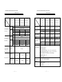
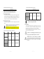
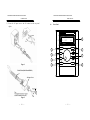
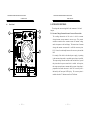
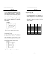
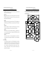
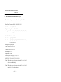
PSH SERIES PROGRAMMABLE POWER SUPPLY USER MANUAL Declaration of Conformity We GOOD WILL INSTRUMENT CO., LTD. No. 95-11, Pao-Chung Rd., Hsin-Tien City, Taipei Hsien, Taiwan declares that the below mentioned product PSH-1036/2018/3610/6006 PSH-1070/2035/3620/6012 PSH-10100/2050/3630/6018 are herewith confirmed to comply with the requirements set out in the Council Directive on the Approximation of the Law of Member States relating to Electromagnetic Compatibility (89/336/EEC, 92/31/EEC, 93/68/EEC) and Low Voltage Equipment Directive (73/23/EEC). For the evaluation regarding the Electromagnetic Compatibility and Low Voltage Equipment Directive, the following standards were applied: ◎ EMC EN 61326-1: Electrical equipment for measurement, control and laboratory use –– EMC requirements (1997+A1: 1998) Conducted and Radiated Emissions EN 55011: 1991+A1: 1997+A2: 1996 Current Harmonic EN 61000-3-2: 1995+A1: 1998+A2: 1998 +A14: 2000 Voltage Fluctuation EN 61000-3-3: 1995 ------------------------------------------------------------------------- Electrostatic Discharge EN 61000-4-2: 1995 Radiated Immunity EN 61000-4-3: 1996 Electrical Fast Transients EN 61000-4-4: 1995 Surge Immunity EN 61000-4-5: 1995 Conducted Susceptibility EN 61000-4-6: 1996 Voltage Dips/ Interrupts EN 61000-4-11: 1994 ◎ Safety Low Voltage Equipment Directive 73/23/EEC & amended by 93/68/EEC CONTENTS PAGE 1. PRODUCT INTRODUCTION................................................. 1 1-1. Description… … … … … … … … … … … … … … … … … … 1 1-2. Features… … … … … … … … … … … … … … … … … … .… 1 2. TECHNICAL SPECIFICATIONS… … … … … … … … … … 3 3. PRECAUTIONS BEFORE OPERATION… … .… … … … ... 6 3-1. Unpacking the Instrument… … … … … … .… … … … .… . 6 3-2. Checking the Line Voltage… … … … … … … ..… … … … . 6 3-3. Environment… … … … … … … … … … … … … … ..… … ... 7 4. PANEL INTRODUCTION… … … … … … … … ..… … … … ... 8 5. OPERATION METHOD… … … … … … … … … … … … ...… . 13 5-1. Constant Voltage/Constant Current Crossover Characteristic....................................................................... 13 5-2. Output Voltage/Current Setting… … … … … … … ..… … 14 5-3. Over Voltage/Current Protection Setting… … … … … ... 16 5-4. Display Contrast Setting… … .… … … … … … … … … … .. 16 5-5. Buzzer Setting… … … … … … … … … … … … … … … … ... 16 5-6. GPIB/RS-232 Interface Setting… … … … … … … … … … 16 5-7. Remote Error Sensing… … … … … … … … … … … … … .. 17 5-8. Test Lead Selective Table… … … … … … … … … … … … . 19 6. MAINTENANCE… … … … … … … … … ..… … … … … … … .. 20 6-1. Adjustment and Calibration… … … … … … … … … … … 20 6-2. Cleaning… … … … … … … … … … … … … … … … … … … 23 7. THE SYSTEM DIAGRAM AND DESCRIPTION… … … .. 24 7-1.Block Diagram… … … … … … … … … … … … … … … … ... 24 7-2.The Configuration of PSH-series Block System… … .… . 25 EN 61010-1: 1993+A2: 1995 IEC 61010-1: 1990+A2: 1995 USA : UL 3111-1 – First Edition, June 1994 Canada: CSA-C22.2 No. 1010.1-92 i PSH SERIES PROGRAMMABLE POWER SUPPLY PSH SERIES PROGRAMMABLE POWER SUPPLY USER MANUAL USER MANUAL SAFETY TERMS AND SYMBOLS FOR UNITED KINGDOM ONLY These terms may appear in this manual or on the product: NOTE: This lead/appliance must only be wired by competent persons WARNING. Warning statements identify condition or WARNING: THIS APPLIANCE MUST BE EARTHED practices that could result in injury or loss of life. IMPORTANT: The wires in this lead are coloured in accordance with the following code: CAUTION. Caution statements identify conditions or practices that could result in damage to this product or other property. Green/ Yellow: Blue: Brown: Earth Neutral Live (Phase) The following symbols may appear in this manual or on the product: As the colours of the wires in main leads may not correspond with the colours marking identified in your plug/appliance, proceed as follows: The wire which is coloured Green & Yellow must be connected to the Earth terminal marked with the letter E or by the earth symbol DANGER ATTENTION Protective Earth (ground) Frame or Chassis or coloured Green or Green & Yellow. High Voltage refer to Manual Conductor Terminal The wire which is coloured Blue must be connected to the terminal which is marked with the letter N or coloured Blue or Black. Terminal Terminal The wire which is coloured Brown must be connected to the terminal marked with the letter L or P or coloured Brown or Red. If in doubt, consult the instructions provided with the equipment or contact the supplier. ii iii PSH SERIES PROGRAMMABLE POWER SUPPLY PSH SERIES PROGRAMMABLE POWER SUPPLY USER MANUAL USER MANUAL This cable/appliance should be protected by a suitably rated and approved HBC mains fuse: refer to the rating information on the equipment and/or user instructions for details. As a guide, cable of 0.75mm2 should be protected by a 3A or 5A fuse. Larger conductors would normally require 13A types, depending on the connection method used. 1. PRODUCT INTRODUCTION Any moulded mains connector that requires removal /replacement must be destroyed by removal of any fuse & fuse carrier and disposed of immediately, as a plug with bared wires is hazardous if a engaged in live socket. Any re-wiring must be carried out in accordance with the information detailed on this label. auto-testing and auto-control. The series of products have improved 1-1. Description PSH -series Programmable Power Supply is controlled by Micro Processor Unit (MPU) that can easily connect communication interface R S-232 or GPIB to computer in order to satisfy user’s demands for greatly the shortage of the tradit ional big size, heavy weight products. The voltage and current are completely controlled by 12 bits D/A Converter with higher resolution and accuracy. Also, the digitalization of system makes a speedy, precise and convenient input of information controlled by the keyboard and rotation knobs. The adjustment of voltage/current is made by software calibration without manual error that will increase the preciseness of the instrument. The function of Over Voltage Protection (OVP) and Over Current Protection (OCP) is set with software and detected with hardware to achieve protected function precisely and speedily in order to prevent users from danger by using the instrument. 1-2. Features 1) Wide Input Voltage Range and High Power Factor (P.F). 2) High Efficient. 3) Constant Voltage and Constant Current Operation. 4) The protection for Over Voltage, Over Current and Over Heat. iv 1 PSH SERIES PROGRAMMABLE POWER SUPPLY PSH SERIES PROGRAMMABLE POWER SUPPLY USER MANUAL 5) IEEE-488.2 and SCPI Compatible Command set. USER MANUAL 2. TECHNICAL SPECIFICATIONS 6) Remote Control. MODEL 7) Output On/Off Control. 8) Self-test and Software Calibration SPEC. 9) LCD Display 10) Built-in Buzzer Alarm. 11) Select either RS-232C(standard) or GPIB(option). 10V PSH -1036(36A) PSH-1070(70A) PSH -10100(100A) 20V PSH -2018(18A) PSH-2035(35A) PSH -2050(50A) 36V PSH -3610(10A) PSH-3620(20A) PSH -3630(30A) 60V PSH -6006(6A) PSH-6012(12A) PSH -6018(18A) Regulation Load ≦0.1%+5mV (C.V) Line ≦0.05%+5mV ≦0.05% +5mV ≦0.05% +5mV Regulation Load ≦0.2%+5mA ≦0.2%+10mA ≦0.2%+15mA (C.C) Line ≦0.2%+5mA ≦0.2%+10mA ≦0.2%+15mA Ripple & Noise Voltage(mVrms) Current(mArms) Voltage Program Accuracy Current Voltage 2 ≦0.1%+5mV ≦0.1%+5mV ≦10mVrms, 100mVpp 20Hz~20MHz ≦0.2% ≦0.2%+20mA ≦0.2%+40mA ≦0.05%+25mV ≤36V ≦0.05%+50mV >36V 10V ≦0.2%+30mA ≦0.2%+60mA ≦0.2%+90mA 20V ≦0.2%+30mA ≦0.2%+30mA ≦0.2%+60mA 36V ≦0.2%+30mA ≦0.2%+30mA ≦0.2%+30mA 60 V ≦0.2%+30mA ≦0.2%+30mA ≦0.2%+30mA ≤36V 10mV >36V 20mV Program 10V 10mA 20mA 30mA Resolution 20V 10mA 10mA 20mA 36V 10mA 10mA 10mA 60V 10mA 10mA 10mA Current 3 PSH SERIES PROGRAMMABLE POWER SUPPLY PSH SERIES PROGRAMMABLE POWER SUPPLY USER MANUAL MODEL SPEC. 10V PSH -1036(36A) PSH-1070(70A) PSH -10100(100A) 20V 36V 60V Voltage Readback(Meter) Accuracy Readback(Meter) Resolution USER MANUAL 10V PSH -1036(36A) PSH-1070(70A) PSH -10100(100A) PSH -2018(18A) PSH-2035(35A) PSH -2050(50A) 20V PSH -2018(18A) PSH-2035(35A) PSH -2050(50A) PSH -3610(10A) PSH-3620(20A) PSH -3630(30A) 36V PSH -3610(10A) PSH-3620(20A) PSH -3630(30A) 60V PSH -6006(6A) PSH-6012(12A) PSH -6018(18A) PSH -6006(6A) PSH-6012(12A) PSH -6018(18A) ≤36V ≦0.05%+25mV >36V ≦0.05%+50mV ≦0.2% +30mA ≦0.2% +30mA ≦0.2% +30mA ≦0.2% +30mA 10V 20V Current 36V 60V Voltage ≤36V >36V Current ≦0.2% +60mA ≦0.2% +30mA ≦0.2% +30mA ≦0.2% +30mA ≦0.2%+90mA ≦0.2%+60mA ≦0.2%+30mA ≦0.2%+30mA 10mV 20mV 10V 20V 36V 60V 10mA 10mA 10mA 10mA 20mA 10mA 10mA 10mA change from SPEC. Temperature Coefficient 30mA 20mA 10mA 10mA Recovery Time (50% step load MODEL Protection Output ON/OFF Control Display Mechanical Spec. AC Input Operation Environmental ≦2ms CV Mode 25%~75%) Voltage Up (10%~90% Response Time ≤150ms ≦ ≤150ms ≤150ms 95% rating load) Voltage Down (90%~10%, ≧ ≤150ms ≤150ms ≤150ms 4 Rush Current Protection LCD Dimensions (W × H× D) ≤100ppm/ °C ≤100ppm/ °C ≤100ppm/ °C provided provided provided Provided provided provided provided provided provided LCD 108×141 × 388 m/m LCD 188 ×141×388 m/m LCD 268×141× 388 m/m Weight Approx. 3.3 kg Approx. 6.2 kg Approx. 9.3 kg 100-230V 100-230V 100-230V 100-230V Indoor use Altitude up to 2000 m Ambient temperature : To satisfy specifications : 10℃ to 35℃ ( 50 ° F to 95 °F ) Maximum operating ranges: 0℃ to 40℃( 32 °F to 104°F ) Relative humidity: 85% RH(max.) non condensing Installation Category : II Pollution degree 2 Storage Temperature & Humidity -10° to 70℃ , 70%RH (maximum) Accessories Instruction manual… … … … … 1 Cable Gland… … … … … … … .. 1 AC Input Cover… … … … … … 1 10% rating load) Voltage (25±5℃) OVP/OCP/OHP 5 PSH SERIES PROGRAMMABLE POWER SUPPLY PSH SERIES PROGRAMMABLE POWER SUPPLY USER MANUAL USER MANUAL 3. PRECAUTIONS BEFORE OPERATION PSH -10100( 100A) 3-1.Unpacking the Instrument The product has been fully inspected and tested before shipping from the factory. Upon receiving the instrument, please unp ack and inspect it to PSH -2050(50A) 100~230VAC 90~250VAC PSH -3630(30A) 6.3A/250VAC× 3 0.5A/250VAC× 1 check if there is any damage caused during transportation. If any sign of damage is found, notify the bearer and/or the dealer immediately. 3-2.Checking the Line Voltage The product can be applied to 100V~230VAC voltages shown in the table PSH -6018(18A) WARNING. To avoid personal inj ury, disconnect the power cord before removing the fuse holder. below. WARNING. To avoid electrical shock the power cord protective grounding conductor must be connected to ground. AVERISS: Pour éviter les chocs électriques, le fil de terre du cordon secteur doit impérativement être relié à la terre. Replace the required fuses according to the table below: Model AC Input AC Input Range Fuse PSH -1036(36A) 3-3.Environment The normal ambient temperature range of this instrument is from 0 ° to 40°C (32° to 104°F). To operate the instrument exceeding this specific temperature range may cause damage to the circuits of instrument. Do not use the instrument in a place where strong magnetic or electric field exists as it may disturb the measurement. CAUTION ? To avoid damaging the instrument, do not use it in a place where ambient temperature exceeds 40℃. PSH -2018(18A) 100~230VAC 90~250VAC 6.3A/250VAC 100~230VAC 90~250VAC 6.3A/250VAC× 2 0.5A/250VAC× 1 PSH -3610(10A) PSH -6006(6A) PSH -1070(70A) PSH -2035(35A) PSH -3620(20A) WARNING: This is a Class A product. In a domestic environment this product may cause radio interference in which case the user may be required to take adequate measures. PSH -6012(12A) 6 7 PSH SERIES PROGRAMMABLE POWER SUPPLY PSH SERIES PROGRAMMABLE POWER SUPPLY USER MANUAL 4 . PANEL INTRODUCTION 1. Display 2. Power Switch 3. Rotary Encoder 4. Output 5. Vset /Is e t (ENTER) 6. F/C 7. MENU 8. Local (GPIB/RS-232) 9. Cooling Fan 10. GND Terminal 11. +Output Terminal - Output Terminal 12. S+ SM+ M13. Interface Indicate the setting of voltage/current value, output voltage/current value and the status of setting and output. Connect the AC power, then press power switch. Wheel knob. Turn on or off output by pressing the knob. Output voltage and Output current switched setting. [ENTER]: This key is for digit value input or setting confirmation. Switch to wheel knob for coarse and fine adjustment. The selection menu for function setting. PS. If there is no further setting change after switching to MENU 4~5 seconds, it will be back to the previous window or output display window. This key has two function: 1. Clear the remote control and replace with panel control setting. 2. Clear the protection status of power supply. PS. Press and hold the key for 5 seconds to get into calibration mode. A cooling fan. Connect the ground terminal to chassis. Positive output terminal. Negative out put terminal. : : : : a positive input voltage remote sense terminal. a negative input voltage remote sense terminal. a positive output voltage monitoring Terminal. a negative output voltage monitoring terminal. : GPIB or RS-232C communication interface. 8 USER MANUAL 14. AC Power Terminal : AC power input terminal. The input is from 90 to 250Vac. AC Input Cord WARNING: The AC input cord is the disconnect device for the power supply. The input cord must be no longer than 9.84 feet (3m). Be sure the AC input cord is well connected according to Figure 1 and Figure 2 before operation. The recommended AC input cord is specified in the table as follows. Add a non-locking plug suitable for use in the country in which you are operating. Power Cable Outside Cable Gland Wire Type Rating Supply Diameter (Strain Relief) 1 unit 3×18 AWG 60℃min. 5.84~6.73m/m KSS SVT 2 units stranded copper 300V (0.230"~0.265 ") PG-1610 3×14 AWG 60℃min. 9.143~10.03m/m KSS 3 units SJT stranded copper 300V (0.360"~0.395 ") PG-2013 1) Strip the outside insulation on the AC cable approximately 4"(10cm). Trim the wires to make the ground wire is 0.5"(12mm) longer than the other wires and join the toric terminals to each stripped wires individually. 2) Unscrew the base of the strain relief from the helix-shaped body. Insert the base through the outside opening in the AC input cover and screw the locknut securely onto the base from the inside. 3) Insert the AC cable through the strain relief b ase until the outer cable jacket is adjoined with the edge of the base. Tighten the body to the base while holding the cable in place and the cable is fastened securely inside the strain relief. 4) Connect the toric terminals to AC terminals of rear panel individually. 9 PSH SERIES PROGRAMMABLE POWER SUPPLY PSH SERIES PROGRAMMABLE POWER SUPPLY USER MANUAL 5) Screw the AC input cover to the AC terminal on the rear panel tightly. USER MANUAL l Front Panel R PROGRAMMABLE POWER SUPPLY RMT ADRS 10. 10V CV OCP PSH-1036 OUT 36. 10 A POWER LOCAL 8 MENU 2 7 F C 3 6 Figure 1 5 VSET ISET OUTPUT ENTER 4 Cable Gland(with Strain Relief) AC Input Cover Figure 2 10 1 11 PSH SERIES PROGRAMMABLE POWER SUPPLY PSH SERIES PROGRAMMABLE POWER SUPPLY USER MANUAL Rear Panel 5. OPERATION METHOD S 12 M S 11 OUTPUT M 10 檢磁LABEL 5-1. Constant Voltage/Constant Current Crossover Characteristic The working characteristic of this series is called a constant voltage and constant current modes is called the crossover point. US 9 S TE D 116525 C LI The voltage and current unit applied for the instrument is Volt and Ampere. voltage/constant current automatic crossover type. This permits continuous transition from constant current to constant voltage modes in response to the load change. The intersection of constant CONFORMS TO UL STD. UL 3111-1 CERTIFIED TO CSA STD. C22.0 NO. 1010.1 13 R l USER MANUAL Fig.5-1 shows the relationship between this crossover point and the load. For example, if the load is such that the power supply is operating in the constant voltage mode, a regulated output voltage is provided. The output voltage remains constant as the load increases, up until AC L N 100 230 47Vac 560 VA 14 63 520 W Hz MAX 1080 VA 1010 W MAX 1550 VA 1450 W MAX the point where the preset current limit is reached. At that point, the output current becomes constant and the output voltage drop is proportioned to further increases in load. The crossover point is indicated by the front panel LCD display. The crossover point is reached when the CV indicator transfer to CC indicator. 12 13 PSH SERIES PROGRAMMABLE POWER SUPPLY PSH SERIES PROGRAMMABLE POWER SUPPLY USER MANUAL USER MANUAL knob. Now, use the [F/C] key to input the integral or dismal number. Figure 5-1 Constant Voltage/Constant Current Characteristic Similarly, crossover from the constant current to the constant voltage mode automatically occurs from a decrease in load, a good example of this would be seen when chargi ng a 12 volt battery. Initially, the open circuit voltage of the power supply may be preset for 13.8 volts. A low battery will place a heavy load on the supply and it will operate in the constant current mode, which may be adjusted for a 1 amp charging rate. As the battery becomes charged, and its voltage approaches 13.8 volts, its load decreases to the point where it no longer demands the full 1 amp charging rate. This is the crossover point where the power supply goes into the constant voltage mode. 5-2. Output Voltage/Current Setting At first, set to voltage/current setting window or output value displayed window: --Output Voltage Setting: Switch the flashed cursor to voltage input position by pressing [Vset/Iset] key, and modify the setting value by using the wheel 14 Example: Set voltage at 20.00V. Switch the cursor to mV range by using the [F/C] key and adjust the value to number 00 with the rotation knob, then switch the cursor to V range by using the [F/C] key and adjust the value to number 20 with the rotation knob to complete the modification. PS. At the moment, if the OUTPUT is on, the output voltage will be output the corresponding voltage value immediately following the adjustment of the rotation knob. --Output Current Setting: Switch the flashed cursor to current input position by pressing [Vset/Iset] key, and modify the setting value by using the wheel knob. Now, use the [F/C] key to input the integral or dismal number. Exa mple: Set voltage at 18.00A. Switch the cursor to mA range by using the [F/C] key and adjust the value to number 00 with the rotation knob, then switch the cursor to A range by using the [F/C] key and adjust the value to number 18 with the rotation knob to complete the modification. PS. When the load current of output terminal exceeds the current setting value, the instrument is operated under the Constant Current mode (C.C. Mode), if it doesn’t exceed the current setting value, the instrument is operated under the Constant Voltage mode (C.V. Mode). If the maximum output voltage of the instrument is larger than 36V, the minimum adjustable step of the rotation knob is 15 PSH SERIES PROGRAMMABLE POWER SUPPLY USER MANUAL 20mV, if it is smaller than 36V, the minimum adjustable step of the rotation knob is 10mV. 5-3.Over Voltage /Current Protection Setting --Over Voltage Protection Setting: Set to OVP SET window by pressing [MENU], modify the OVP setting value with [F/C] key to input integral or dismal number, then press [ENTER]. --OVP Status Clear Up: When the output voltage exceeds the setting voltage, the instrument will stop output and get into OVP mode by displaying “OVP Error. Press “LOCAL” to reset” messages on the panel. Now press [LOCAL] to clear OVP status, back to previous status. --Over Current Protecti on Setting: Set to OCP SET window by pressing [MENU], then switch OCP to ON or OFF with the knob and press [ENTER]. When the OCP is on, the output current equals or exceeds the setting current, the instrument will stop output and get into OCP mode by displaying “OCP Error. Press “LOCAL” to reset” messages on the panel, Now press [LOCAL] to clear OCP status, back to previous status. 5-4. Display Contrast Setting: Set to Contrast Setting window by pressing [MENU], modify the Contrast setting value with knob, then press [ENTER]. PSH SERIES PROGRAMMABLE POWER SUPPLY USER MANUAL using the wheel knob to modify the value and press [ENTER] to complete the setting. Note: The system will detect the interface used at present automatically, and switch the detected interface over the setting interface of GPIB or RS-232. Example: 1) If want to set the GPIB address value to 08: Set to interface window by pressing [MENU], and adjust the address value to 08 with the wheel knob and p ress [ENTER] to complete the setting. 2) If want to set the RS-232 Baud Rate to 9600: Set to interface window by pressing [MENU], and adjust the Baud Rate value to 9600 with the wheel knob and press [ENTER] to complete the setting. For further details, please refer to the programmer manual of PST/PSS/PSH series programmable power supply. 5-7. Remote Error Sensing A normal power supply can perform its best load regulation, line regulation, low output impedance, and low output ripple and noise, as well as the rapidly transient recovery response. Please refer to figure 5-2. If there is any test lead connected between load and output terminal, the best characters of power supply can not be shown up on the load terminal. 5-5. Buzzer Setting Set to Buzzer Set window by pressing [MENU], switch Buzzer to ON or OFF with the knob, then press [ENTER]. 5-6. GPIB/RS232 Interface Setting Set to Interface window by pressing [MENU]. If the GPIB is displayed, the Address value window will be appeared, if the RS-232 is displayed, the Baud Rate window will be appeared, then 16 Figure 5-2 The power supply with local error sensing 17 PSH SERIES PROGRAMMABLE POWER SUPPLY PSH SERIES PROGRAMMABLE POWER SUPPLY USER MANUAL The function of the Remote Error Sensing can only be applied to the Constant Voltage mode as shown in Figure 5-3. The feedback point of power supply must start from the load terminal directly. Therefore, the power supply can display its function on the load terminal instead of output terminal. To compensate the voltage drop causing from the test lead, it needs to shift the voltage from the output terminal of power supply, and the voltage on the load terminal remains unchanged. Figure 5-3 The power supply with remote error sensing Error Sensing Open Protection The sensing circuit must avoid open circuit without equipping with Relay, Switch, and Connector. When the open circuit is occurred USER MANUAL 5-8. Test Lead Selective Table When we use PSH -SER models power supply, the test lead must have an enough current capacity to prevent from damaged. The following is test lead selective table shows the maximum current rating, based on 450A/cm2. A large test lead is recommended in order to reduce the voltage drop as less as better on the test lead (typical 0.5V maximum). Wire Size (AWG) 20 18 16 14 12 10 8 Max. Current (A) 2.5 4 6 10 16 21 36 Wire Size (AWG) 6 4 2 1 1/0 2/0 abruptly on the sensing circuit, it will cause overshoot on the output terminal. To prevent this kind of phenomenon, add small resistance R1 and R2 or replace with diode as shown in the Figure 5-4. Figure 5-4 The power supply with remote error sensing protection 18 19 Max. Current (A) 61 97 155 192 247 303 PSH SERIES PROGRAMMABLE POWER SUPPLY PSH SERIES PROGRAMMABLE POWER SUPPLY USER MANUAL 6. MAINTENANCE USER MANUAL 1mV/AMP(± 0.25%) Current Shunt. Besides, the current rating of WARNING The following instructions are executed by qualified personnel only. To avoid electrical shock, do no perform any servicing other than the operating instructions unless you are qualified to do so. Warning: Do not remove covers. Refer servicing to qualified personnel. AVERTISS: Ne pas enlever le capot. Seul un personnel habilité peut intervenir sur le matériel. the output load must be larger than the 10% of the output current at least. --Preparation 1) 30 minutes warm up before calibration. 2) Ambient temperature:23 ±5°C, Humidity: Under RH70%. 3) When the instrument is powered on but not yet output, use multimeter to measure TP301 AND TP302, adjust VR303 to Warning: No operator serviceable components inside. AVERTISS:Pas de maintenance sur les composants internes. Warning: For continued fire protection. Replace fuse only with 250V fuse of the specific type and rating, and disconnect power cord before replacing fuse. AVERTISS: Pour une protection contre les risques d’incendie, ensure the difference of voltage between two parts is at -10V DC, then measure TP303 and TP304, adjust VR302 to make TP303 larger than TP304 to be ab out 100mVD C. If the Unit 2 and Unit 3 are included to the equipment, measure TP501 and TP502, adjust VR501 to ensure the difference of voltage between two points is -10VD C, and the TP504 among the Unit 2 and Unit 3 must be larger than TP503 to be about 40m V DC. remplacer le fusible exclusivement par un modèle aux caractéristiques équivalentes. 6-1. ADJUSTMENT AND CALIBRATION The instrument has been fully calibrated at factory before delivery. --Output Calibration Steps: [Step 1] The readjustment is suggested only when the circuit of the Repress [LOCAL] for 4~5 seconds, the window will appear “Please enter the password” (vary with different models: PSH -1036: 1036, instrument is modified, or the instrument is proved exceeding the PSH -6006: 6006), now input the value number with the knob and use specification by the sophisticated measured equipment. However, the accuracy of the calibrated multimeter must be within ±0.1% or [F/C] key to move key -in position, then press [ENTER] key. When the value number is input by mistake, the system will jump out this mode. better (GW model GDM-8145G or the equivalent equipment) and [Step 2] Voltage Calibration Steps 20 21 PSH SERIES PROGRAMMABLE POWER SUPPLY PSH SERIES PROGRAMMABLE POWER SUPPLY USER MANUAL At first, set the DMM to 200V voltage range. USER MANUAL [Step 2.1] Get into the window of Calibration item, select the item of Voltage calibration with knob and press [ENTER]. [Step 2.2] Input measured voltage value (Min) with the knob and press [ENTER]. During the value input, use [F/C] key to switch over the integral or dismal number input. [Step 2.3] Now, adjust VR301 properly for the measured voltage (Max) of DMM according to the value displayed in the window, then press [ENTER]. Note: During the adjustment, the maximum distortion range of the measured value is at 0.005V. [Step 3] Current Calibration Steps At first, make sure the output is disconnected with test leads, if the specification of current is smaller than 20A, can either use 20A range of GDM -8145G or connect current shunt to output terminal to measure the output current. If the specification of curr ent is larger than 20A, must connect current shunt to output terminal to measure both ends of the current shunt with 200mV range of DMM. [Step 3.1] Get into the window of Calibration item, select the item of current calibration with knob and press [ENTER] to start Current Calibration Steps. [Step 3.2] Input measured voltage value (Max) with the knob and press 22 23 PSH SERIES PROGRAMMABLE POWER SUPPLY PSH SERIES PROGRAMMABLE POWER SUPPLY USER MANUAL [ENTER]. During the value input, use [F/C] key to switch over the integral or dismal number input. USER MANUAL 7. THE SYSTEM DIAGRAM AND DESCRIPTION 7-1. Block Diagram [Step 3.3] Input measured voltage value (Min) with the knob and press Unit 1 OptoIsolator [ENTER]. During the value input, use [F/C] key to switch over the integral or dismal number input. Pulse Width Modulator Driver Circuit Power Factor Corrector Power Stage Error Amplifier [Step 4] Unplug the test lead, switch to the window of OVP calibration item with the knob, press [ENTER] to start automatically OVP calibration item [Step 4.1] Now, the window will display the calibration progress. After the AC Input Post Regulator Reference + 15V -15V +5V1 Auxiliary Power D To A Converter Or Gate calibration is finished, the system will jump out the window. [Step 5] After make sure all the calibration procedure is completed and correct, switch the window to Save and press [ENTER] key to finish LCM Display Analog Switch and Sample Hold Micro Control Current Control Circuit the calibration procedure. [Step 6] If it is not necessary to store the calibration data, just switch to EXIT with the knob and press [ENTER] to leave the calibration window. Voltage Control Circuit Interface RS-232 or GPIB Keyboard Unit 2 Unit 3 6-2. Cleaning To clean the power supply, use a soft cloth dampened in a solution of mild detergent and water. Do not spray cleaner directly onto the instrument, since it may leak into the cabinet and cause damage. Do not use chemicals containing benzine, benzene, toluene, xylene, acetone, or similar solvents. Do not use abrasiv e cleaners on any portion of the instrument. 24 25 O/P PSH SERIES PROGRAMMABLE POWER SUPPLY USER MANUAL 7-2. The Configuration of PSH-series Block System The whole Block system consists of the foll owing Circuit Blocks: Power Factor Corrector: BD101, Q101-Q103, D102. Micro Processor Unit (MPU): U308 Digital to Analog Converter (DAC): U316. Analog Switch Circuit: U328, R356, R363, R370, C314, C318, C320, U331. Pulse Width Modulation: U206. Driver C ircuit: Q202 -Q203, T202. Power Stage: Q204 -Q205, Q211-Q212, T203, D207 -D208, L201, C246-C249, C253. Post Regulator: Q207, Q208. Voltage Control Circuit: U334. Current Control Circuit: U334. Error Amplifier: U333. Opto-isolator: U209. Auxiliary Power supply : Q201, U203, T201. OVP: U315, U331, Q209, U327, Q310, U328. Unit 2: When the power reaches about 2 times the Unit 1, the Unit 2 will be used additionally. Unit 3: When the power reaches about 3 times the Unit 1, the Unit 2 and Unit 3 will be used additio nally. 26