1
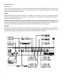
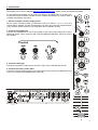
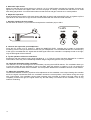
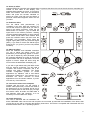
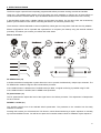
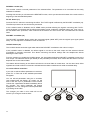
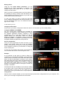
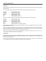
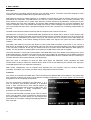
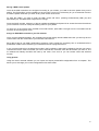
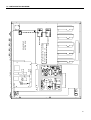
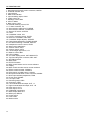
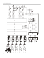
USER MANUAL
LIST OF CONTENTS
1. IMPORTANT REMARK
04
2. INTRODUCTION
05
3. INSTALLATION
06
4. QUICK START
09
5. OPERATION AND USAGE
15
6. EFFECTS PROCESSOR
19
7. INTERNAL SOUNDCARD
23
8. MIDI CONTROL
24
9. SETTINGS MENU
28
10. SETTING UP YOUR MIXER
31
11. FURTHER CONSIDERATIONS
32
12. TECHNICAL CHARACTERISTICS
33
13. CONFIGURATION DIAGRAM
35
14. FUNCTION LIST
36
15. FUNCTION DIAGRAM
37
16. BLOCK DIAGRAM
38
All numbers subject to variation due to production tolerances. ECLER S.A. reserves the right to make changes or
improvements in manufacturing or design which may affect specifications.
3
1. IMPORTANT REMARK
License
This product contains software elements, subject to public software licenses as for example GPL and LPGL. For
further details you may visit http://www.ecler.es/gnu/evo5.
Safety Instructions
In order to get the optimum operation and efficiency from your mixing unit, it is VERY IMPORTANT - before you
plug anything - to read this manual very carefully and take seriously into account all considerations specified within
it. We strongly recommend that its maintenance be carried out by our Authorised Technical Services.
This apparatus must be earthed through its mains cable.
Do not expose the unit to rain or water splashes, and do not place liquid containers or incandescent
objects like candles on top of the unit. Do not obstruct the ventilation shafts with any kind of material.
Any change in the configuration of the unit must be carried out by a qualified technician. Should any
connection / disconnection task be done, always disconnect the unit from the mains supply.
Warranty Descriptions
Your ECLER equipment has undergone exhaustive laboratory and quality control tests before leaving the factory.
Nevertheless, your may be in need of our Technical Service during the period covered by the Guarantee or
afterwards. In that case, carefully protect your equipment in its original packet and send it to our Technical Service
with the transport and insurance paid. Attach a photocopy of your Guarantee Certificate and a detailed description
of the defect you have observed.
ECLER S.A. guarantees the EVO5 mixer against material defects and manufacturing faults for the period of one
year, starting from the original purchase date.
ECLER, S.A., will repair the defective equipment within the aforementioned period, with no charge for parts and
labour.
To ensure the validity of the Guarantee, it is essential that the attached Guarantee, Registration Card is filled out
correctly and remitted to your ECLER distributor, within 10 DAYS after date of purchase.
The Guarantee is non-transferrable and protects the original buyer only.
The Guarantee does not cover:
Damages caused by mistreatment or negligent handling, lack of elementary precautions, disregard to the
instructions in the manual, faulty connection or accidents.
ECLER, S.A., will not be held responsible for any direct or indirect damage, loss or other damage originated by or
relating to the set.
* sets that have been manipulated, altered or repaired other than at the authorized Technical Service centers.
* the exterior fittings and electro-mechanical parts, nor their wear due to use.
* shipping and insurance expenses, nor for damages the set may incur during its transport.
This Guaranteed is valid only for repairs or services carried out at an authorized Technical Service Center.
The liquid crystal display is manufactured with high-precision technology. However, some units may have pixels (up
to 4) that are continuously glowing or turned off. This is not a malfunction.
4
2. INTRODUCTION
Congratulations for acquiring a genuine, professional ECLER device! The EVO5 is the latest design from ECLER, a
legendary company from Barcelona with over 42 years of experience in designing and manufacturing professional
audio equipment.
The EVO5 is a perfect tool for today’s DJs and producers thanks to its unique combination of a 12 channel firewire
soundcard, the highest digital audio quality with 24 bits and 96 KHz, MIDI Control, full colour display and a
completely programmable effects processor.
This genuine mixer uses the best available components and 24 bit A/D and D/A converters in order to obtain the
best sound quality. Due to the over 40 years of experience in designing professional audio equipment, the circuits
are very efficient and the digital sound has the same warmness as any analogue device. All circuits are
manufactured and tested in our factory in Barcelona.
The internal soundcard has 12 input and 12 output channels. All of them have low latency thanks to the usage of
firewire technology. A single cable allows transmission and reception of all these audio channels and all the MIDI
Control data. This compact card turns the EVO5 into an ideal sound desk for music production, live acts and the
most advanced DJ sessions, which combine the traditional vinyl, CD players and avant-garde software as LIVE or
TRAKTOR.
The effects unit has a crystal clear sound due to the standard quality of 24 bits and 96 KHz. All effects can be
completely programmed. There are 9 basic effects that can edited according to the user’s needs and it is also
possible to create new effects by chaining two different basic effects and programming them as wanted. Up to 64
different effects can be created and saved. Using a computer and the external software, it is possible to import and
export the personal effects configurations. This allows you to exchange your sounds with other artists.
The MIDI control is nearly unlimited thanks to the 69 controllers and the 64 available parameter patterns. The
EVO5 wears a MIDI control section with 6 push buttons and 4 encoders which can be rotated and pressed. The full
colour display allows creating and viewing labels that allow you to know which function is executed by which
controller in each moment. The channel controllers can be individually set up to send MIDI data or to work as audio
controllers. The external software also allows to import and export MIDI configurations.
The mixer’s display is unique in its class and converts the EVO5 into the world’s first mixer that offers such a
feature. This high quality display with 320 x 240 pixels raises the flexibility, since it is possible to edit all of the
mixer’s parameters in real-time. Using the display you can adjust all of the mixer’s functions as, for example, the
tone controls, the input and output sensitivities, the fader and crossfader curves, the MIDI controls, the BPM
counter … even the output limiter that has been installed to tranquilize the sound technicians and engineers!
Finally, this unique mixer has been designed by GIUGIARO DESIGN, one of the world’s most prestigious
th
companies in product design and prize awarded as the best car designer of the 20 century. With this design,
GIUGIARO has been looking for a perfect harmony between the well-known and plain ECLER design and the
innovation of such a revolutionary product as the EVO5.
5
3. INSTALLATION
The first thing to take into consideration when placing your EVO5 is your comfort and an easy access to all the
connections.
The EVO5 is basically conceived as a tabletop mixer and its usual placement
will be between two vinyls or CD players. The mixer has a 370 mm depth and
432.6 mm) width format. The optional metallic side profiles kit allows you to
firmly fix your mixer to the surface over which it is placed or over its own
profiles. These profiles also allow to tilt the mixer's position for an easier
operation.
Because of the high gain of the PHONO and MICROPHONE inputs, always try
to place the mixer as far away as possible from noise sources (dimmers,
engines, etc.) and mains wires. For the very same reason, and under any circumstance, you should never remove
the unit's metallic cover.
The power consumption of the EVO5 is very low, so they do not need any cooling, but you should avoid extreme
temperatures and the atmosphere should be as dry and dust free as possible.
The EVO5 operates now with a new universal input power supply “Switching Power Supply” and can perfectly
works without any internal modification from 90V to 264V – 47 to 63Hz. Make sure that the mains-wire is far away
from the signal-cables in order to avoid any possible audio hum.
In order to protect the unit from an eventual electrical overload it carries a T 1A fuse. Should it ever blow up, unplug
the unit from mains and replace it with an identical one. If the new fuse blows again contact immediately with our
authorized technical service.
ATTENTION: NEVER SHORT-CIRCUIT THE SECURITY PATH NOR USE A HIGHER VALUE FUSE.
CAUTION: Fuse substitutions have to be performed by a qualified technician.
Audio input connections
MIC 1
PHONO 1
LINE 1
PHONO 2
LINE 2
PHONO 3
LINE 3
PHONO 4
LINE 4
Microphone 1
Turntable 1
CD Deck 1
Turntable 2
CD Deck 2
Turntable 3
CD Deck 3
Turntable 4
CD Deck 4
Phono Inputs
Phono Turntables must be fitted with a magnetic cartridge with nominal output level of -40dBV (10 mV). The
PHONO inputs (42) of the EVO5 have a high headroom (margin before saturation) and it can handle higher output
cartridges than what is usual.
Line Inputs
The sensitivity of the inputs marked as LINE (43) is 0dBV (1V). You can connect sound sources such as CD, DAT
or MP3 players, as well as keyboards and other instruments.
6
Microphone Inputs
The MICRO inputs (1, 40) are prepared for a nominal input level of -40dBV. The connectors combine both, JACK
and XLR3, formats. With the TRIM controller it is possible to adjust the input sensitivity between -30 and -50dBV.
These microphone inputs are prepared for balanced signals, which have to be connected as follows:
Hot or direct signal
Cold or inverted signal
Ground
>
>
>
Pin 2
Pin 3
Pin 1
Tip
Ring
Sleeve
Microphones must have low impedance (200 to 600Ω) and must be mono. For unbalanced connections, it is
necessary to short-circuit pin 3 to ground or the central ring. The EVO5 equips an 18V phantom power supply for
condenser microphones. An internal soldering jumper allows enabling/disabling the phantom power. The EVO5’s
MICRO channel is delivered from factory with enabled phantom power. See configuration diagram.
Audio outputs connections
OUT 1
OUT 2
REC frontal
REC posterior
Headphones
Main power amplifier
Booth/Room2 power amplifier
Recording device 1
Recording device 2
Headphones
OUT 1
This stereo output is the one to feed the PA-system using balanced XLR3 connectors or unbalanced RCA
connectors. The nominal output level for OUT 1 (46, 47, 48) is set to 0dBV (1V), which can be modified via
software to 0, +3 or +6dB. The OUT 1’s output volume can be controlled using the OUT 1 potentiometer (24).
Near the OUT 1 controller you will find the L+R switch (26), which adds left and right signals from OUT 1 and
OUT 2 outputs. This function is especially useful if a malfunction occurs on one of both channels during a session
(for example: a bad contact of the turntable’s needle). Activating this switch, the mixer sends the sum L+R to the
loudspeakers, so that the major part of the audience will not notice this failure.
OUT 1 and OUT 2 are equipped with a balance controller BAL (27).
OUT 2
Normally this one is used to obtain an independent output for the DJ booth. This stereo output OUT 2 (49) equips
unbalanced RCA connectors and its nominal output level is set to 0dBV (1V), which can be modified via software to
0dB, +3dB or +6dB. The OUT 2’s output volume can be controlled using the OUT 2 potentiometer (25).
Record outputs
There are two REC outputs, which use RCA connectors, one located on the back plate (44) and the other located
on the control surface (30). These two REC outputs are connected in parallel, but they can be used simultaneously
without any problems. The nominal output level is 0dBV (1V) for both REC outputs. Using the software it is possible
to select the signal source for the REC outputs, which can be either the MIX signal (default) or the PFL signal.
Headphones
In order to obtain an optimal performance during their operation, the headphones should have high impedance
(200-600Ω). Headphones are connected to the headphones output (23) located on the controllers plate. A
normalized ¼’’ stereo jack or 3,5mm mini-jack is provided for this connection. The sleeve is ground, the ring is the
right channel and the tip the left channel.
7
Digital connections
Firewire port
On the mixer’s back plate there are two firewire connectors (50) with 6 pins (IEEE1394) that work as a hub. The
firewire port allows connecting the mixer to a computer and send up to 12 audio input channels, 12 audio output
channels and even the MIDI control data.
MIDI IN
MIDI (Musical Instruments Digital Interface) is a standard communications protocol for connections between
electronic musical instruments and computers. The procedures of connecting and controlling MIDI devices are
described in chapter 8 (MIDI control).
The MIDI IN connector (52) is DIN 5 (180º) which allows you to connect other MIDI devices to the EVO5. If you
connect a MIDI device to MIDI IN input, all the MIDI data that arrive (except MIDI clock) will be forwarded to the
computer via the firewire port. This feature turns the EVO5 into a MIDI data converter from DIN 5 to firewire. You
may also send a MIDI clock signal to the EVO5 from another MIDI device which is not a computer.
MIDI OUT
All MIDI data that arrives from the computer through the firewire port and is not addressed to the EVO5 will be
forwarded by this output. This feature turns the EVO5 into a MIDI data converter from firewire to MIDI (Din 5). You
may also send the MIDI clock signal from the EVO5 if this has been activated via software.
CD Deck
Minidisc
Sequencer
CD Deck
Microphone
Power amplifier
CD Deck
Controller
MAINS INPUT
OUTPUTS
FUSE: T 1A 5x20
MIDI IN
INPUT 4
INPUT 3
INPUT 2
INPUT 1
INPUT 0
MIDI OUT
-30 dB -50
IEEE 1394
OUT 2
OUT 1
R
OUT 1
L
PIN 1 = GND, PIN 2 = HOT, PIN 3 = COLD
REC
LINE
PHONO
GND
LINE
PHONO
GND
LINE
PHONO
GND
LINE
PHONO
GND
TRIM
MICRO
Turntable
Turntable
Turntable
Turntable
Computer
Power amplifier
8
4. QUICK START
We suggest you to visit our website http://www.eclerdjdivision.com/, where you will find further information.
For the following procedure you will need a CD player and headphones. If you also wish
to experiment with the MIDI controller and the internal soundcard you will also need a
computer with firewire connection.
1. Set the controllers to their initial position.
Set the rotary controllers GAIN, HI, MID and LOW from channel 1 (5, 6, 7, 9) to the
central snap-in position. Put the channel fader (15) down and move the A/OFF/B switch
(14) to position A (this channel is now assigned to the crossfaders' A side).
2. Connect the headphones.
Connect your headphones to one of the outputs on the mixer's front panel (23). Set the
MONITOR LEVEL (22) to minimum and move the MONITOR SELECT control (21) to the
PFL position.
3. Connect a CD player.
Connect a CD player to LINE input on channel 1 (43), insert a CD and play the CD.
4. Connect the mixer's power cable.
Connect the power cable to power source input (55) on the mixer's back side and turn the
mixer on by pressing the MAINS INPUT switch (53).
9
5. Select the input source.
Make sure that the input source selector on channel 1 (3) is in LINE position and that the channel's VU-meter (8)
lightens up. If this does not happen make sure that CD player is correctly connected and that there is an audio
track being played back. You should also make sure that the tone and gain controls are in central position.
6. Adjust the input level.
Move the GAIN control until the VU-meter shows 0dB. Each channel's red overload LED OVL (2), lightens up if the
input level for this channel is to high and has to be diminished with the channel's GAIN controller.
7. Send the signal to the main output.
Set the fader on channel 1 (15) to maximum and place the crossfader (16) on side A.
8. Listen to the signal with your headphones.
Press the PFL button (10) on channel 1. Adjust the MONITOR LEVEL controller (22) to obtain a comfortable
monitoring volume. Now you should hear music with your headphones. Turn the MONITOR SELECT controller (21)
to the right to crossfade the PFL signal and the MIX signal. When this controller is completely turned to the right,
only the MIX signal will be monitored.
9. Try the operation of the tone controllers.
Experiment with this powerful 3-way stereo equaliser (6, 7, 9). This tone control has been designed for a creative
sound edition: each way can be individually isolated using the big and ergonomic rotary controllers.
10. Check the adjustment of the crossfader.
The channels 1 to 4 can be assigned to the crossfader (16) using the A/OFF/B selector. The crossfader allows you
to melt the signals that are assigned to both of its sides. With this selector in position A or B, you assign the
channel to one of both sides of the crossfader. The OFF position disables the crossfader's function on this channel.
11. Adjust the crossfader curve.
The XFADER SHAPE controller (19) allows a fine adjustment of the crossfader curve's slope. Setting this controller
all left, the signal is diminished when the crossfader reaches the central position, which allows mixing two songs
with a soft melting. The crossfader curve's slope increases if the controller is turned to the right. When is gets
completely turned to the right, the signal enters very fast with hardly a movement of the crossfader. This is very
useful for scratching.
10
12. Select an effect.
Hold the EFFECTS controller (33) pressed while you press at the same time one of the six shortcut controllers (34)
located at both sides of the display. The
selected effect appears on screen. If you wish to
select more effects, hold down the EFFECTS
button and press the encoder identified on
screen as LOAD. A list with up to 64 effects or
personal combinations appears. Select the one
you want.
13. Enable an effect.
Turn the effects send potentiometer (11)
completely to the right. With this controller you
can set the amount of signal level you want to
send to the effects processor. Press the FX
SEND button on channel 1 (12) to enable the
signal send to the effects processor. Sending
can be activated independently for each channel
which makes sound edition more flexible. Now
press the LAUNCH button (39) and move the
DRY/WET (18) crossfader, which melts the
original signal (DRY) with the processed signal
(WET). If you want to monitor the effects signal,
press FX PFL (17) (even if you have not pressed
LAUNCH).
14. Adjust an effect.
Move the PARAM1 and PARAM2 controllers
(37, 38) to adjust the effects sound. The
parameters you are adjusting appear on screen.
If you wish to adjust any other parameter, press
the controller identified on screen as FX1/2 and
all parameters that can be adjusted in real-time
appear on screen. Adjust the effect using the
four encoders located below the display (36).
If you wish to get started using the MIDI control
and the internal soundcard, you will need a
computer with firewire connection and a DJ
software with MIDI capabilities. The EVO5
includes configuration presets to control
applications as Ableton's LIVE 6 and Native
Instruments' TRAKTOR 3. We suggest you to
download the demo versions of these
applications from the owner's website, if you do
not have any of this software.
15. Connect the mixer to the computer.
Together with the mixer, you will receive a
firewire cable (IEEE1394). Connect this cable to
the firewire port on your computer and to one of
the two firewire ports on the mixer (50). Through
this firewire cable, all audio and MIDI data is
sent between mixer and computer. It is not
necessary to use the MIDI OUT output.
16. Install the drivers.
The mixer is delivered with an installation CD
and a FIREWIRE cable. Once mixer and computer are connected, proceed with the installation of the drivers that
you will find on the CD by executing the following instructions. The EVO5 is compatible with Windows® XP SP2
and Macintosh® OSX v 10.X. operating systems.
11
Windows XP SP2
Once you connected the mixer to the computer, the message "New hardware found. Ecler EVO5" will pop up.
The new hardware found wizard will open. Select the option "No, not this time" and press "Next". Select the option
"Install from a list or specific location (advanced)".
Introduce manually the complete drivers' path or select it with the "Browse" option.
12
When the warning appears, press "Continue Anyway". Finish the installation.
A new pop-up informs you that the installation has been successfully completed.
If you want to make sure that the drivers are correctly installed, open the "Device Manager", where the mixer will
appear as "Ecler EVO5" in the chapter "Sound, video and game controllers".
13
MAC OSX v 10.X
The software will automatically detect and install the necessary drivers. The mixer will appear as input/output
device in the "System settings" in the chapter "sound".
If you wish to use the mixer as default soundcard on your computer, open the "Audio and MIDI settings" and set the
necessary parameters.
17. Configure the soundcard for your DJ software.
Each DJ application has a different method to configure the soundcard. Open your software and enter the audio
device management section. Your software will recognize the mixer's soundcard as "Ecler EVO ASIO Driver".
Assign the soundcard's 12 input and 12 output channels to the software channels you wish.
18. Play back a digital sound file.
Once your soundcard is correctly configured, play back a digital music file with your DJ software. Set the input
selector (3) on channel 1 to FireWire CH1-2 position. The channel's VU-meter will lighten up and you can adjust the
input signal with the GAIN and tone controllers as you did before with the analogue signal.
19. Select a MIDI control pattern.
The EVO5 offers 64 different MIDI control patterns and configurations for applications as LIVE 6 and TRAKTOR 3.
Press EFFECTS (33) and the encoder identified on screen as LOAD. A list with 64 available patterns will appear.
Select an "EMPTY" pattern and try using it.
20. Assign a command to a MIDI controller.
Each DJ application uses a different MIDI configuration procedure. Take your time to get through all the MIDI
control possibilities offered by your software and to find out how to programme them. Now select the function you
want to control and move the mixer’s controller you want to execute this function when the MIDI device asks you to
do so. The device will identify the MIDI note sent by the mixer. From now on you will be able to remote control this
function. The controllers located around the display send MIDI data if this mode has been activated using the MIDI
button (32). The channel and output controllers instead, have to be configured to send MIDI data (a blue LED
indicates that the input channels are working in MIDI mode).
14
5. OPERATION AND USAGE
Start-up
This can be done pressing the POWER switch (53) located at the back plate and immediately the EFFECTS, MIDI
and SETTINGS controllers will glow up green and the mixer’s welcome screen will appear.
The EVO5 is equipped with automatic mute circuits on all main outputs, which activate during the mixer’s powerup/power-down and during changes in the sampling frequency.
Thanks to these circuits, the introduced noise due to turning the EVO5 on or off is the lowest possible. However it
is strongly recommended to turn on all the devices in the following order:
1. Sound sources.
2. Mixer, equalizers, active filters.
3. Finally, power amplifiers.
Powering off should be done by following the exact reverse sequence in order to avoid any possible damage to the
loudspeakers.
Control Description
Input selector
The channels 1-4 have a tilting input source selector (3), which allows the user to choose between different types
of input: turntable (PHONO), CD player or similar (LINE) or a stereo channel from the internal firewire soundcard.
Channel GAIN
All the EVO5 input channels have an accessible input sensitivity GAIN control (5). The GAIN controls adjust the
input level of each channel in order to compensate the different sources connected to the mixer. The gain
adjustments have to be executed with extreme care using the VU-meters (8) and the OVL (2) as reference.
The standard reference level used to mix audio signals is 0dB. To obtain an optimal mix adjust the input level so
that the value shown on the VU-meter stays always close to 0dB and make sure you never reach the clipping level,
using the red LED’s from the VU-meter and the OVL indicator from each channel as reference.
Equalization
The rotary tone controls for each channels provide a +10/-30dB boost/cut at high (9) and low frequencies (6) and
+10/-25dB at the mid range (7). This great attenuation range is specially designed for creative live performance.
The tone control is completely editable via software (see chapter 10 settings menu) which allows you to choose the
style, frequency range and gains. The type and the configuration chosen via software are common to the channels
1-4, but can be different for the microphone channel. You can bypass the tone control via software (which disables
this function).
ATTENTION: Use equalization carefully, by boosting too much the low frequency range, you can induce an
excessive displacement of the speakers membrane.
15
Monitoring System
The EVO5 is equipped with an easy and flexible monitoring system that allows the artist to adjust with great
precision the effects and mix levels for each input channel using the VU-meters and headphones.
Each channel as well as the effect processing can be monitorized visually and pre-listened pressing the dedicated
PFL (10) and/or FX PFL (17) yellow led button. Each channel has a VU-meter that shows the PFL L+R signal level.
A main VU-meter with two columns L and R show the OUT 1, MIX or OUT 2 signal level, depending on the position
of the selector located just above the VU-meter (29).
For HEADPHONES monitoring, the SELECT PFL/MIX rotary potentiometer (21) allows you to blend a selected PFL
together and/or FX PFL with the main MIX Program. The LEVEL rotary potentiometer (22) controls the level of
headphones output.
Sending from channel to effects
By pressing the FX SEND button (12), which glows up blue, the channel's signal is sent to the internal effects
processor. A potentiometer allows adjusting the level of the signal sent to the effects processor between 0 and
100% (11).
For further instructions concerning the internal effects processor, please read chapter 7.
Faders
The EVO5 equips ECLER's 60mm faders (15). These faders are very precise, their movement is very smooth and
they have a very fast cut.
The SHAPE FADER controller (20) adjusts the slope of the fader's curve, which allows you to distribute the signal
level over all the length of the fader. For example, you can select a linear curve (controller in central position), so
that the signal level is raised progressively and proportionally to the fader's position. Turning the controller
completely to the right, the signal enters at full level with hardly a movement of the crossfader. Turning the
controller completely to the left the signal enters at full level when the fader is about to reach the opposite side.
Crossfader
All channels, except the MICRO channel (channel 0), can be assigned to the EVO5's crossfader using the A/OFF/B
switches, located on all the channels (14). The positions A and B assign the signal to one of both sides of the
crossfader, while the OFF position disables the crossfader's function on this channel.
The SHAPE XFADER (19) adjusts the slope of the crossfader's curve. The range of adjustable positions allows the
creation of a soft melting between two music tracks (controller set completely to the right side), as well as fast cuts
which are excellent for scratching techniques (controller set completely to the left side). Via software you can also
adjust the CUT IN TIME (in millimetres), which is the distance between the physical end of the crossfader and the
first entrance point of the signal.
The EVO5 is compatible with the ECLER ETERNAL scratch crossfader with inductive technology based on a
magnetic control system. This contact less technology, combined with an exclusive magnetic sliding system, offers
a soft feeling and one of the most precise crossfaders that actually exists. The inductive ETERNAL crossfader has
been specifically designed for extreme "turntablism" techniques which require an extremely smooth and fast
crossfader movement.
Internal effects controls
Please read chapter 6.
TALKOVER function
The microphone channel 0 has a TALKOVER function. The red glowing button (13) activates the TALKOVER,
which diminishes the program signal when there is signal present on the microphone. The time that the program
signal needs to recover, as well as the amount of attenuation, can be set via software.
16
OUT 1 and OUT 2 output levels
The EVO5 equips two main output controllers OUT 1 and OUT 2. The OUT 1 level can be adjusted with the OUT 1
potentiometer (24) while the OUT 2 controller adjusts the OUT 2 level (25). Both can be monitored with the main
VU-meter using the OUT 1/MIX/OUT 2 switch (29) and can also be edited with the L+R controller and the balance
controller (BAL).
Via software you can assign an intelligent and fully programmable multiband compressor to one of both outputs
(see chapter 10, Settings Menu).
Screen descriptions
SHORTCUT NUMBER
FX 2 BEAT SYNC
EFFECT MODIFIED BY USER
EFFECT'S NAME
BPM INDICATOR
BPM CONFIDENCE
LEVEL
FX 1 BEAT SYNC
BPM SOURCE:
MIX/FX/MIDI
CLOCK/TAP
EFFECT 1 TYPE
EFFECT 2 TYPE
MIDI COMMAND ASSIGNMENTS
TAP FUNCTION
TURNING FUNCTION
17
MIDI TRANSMISSION
MIDI CLOCK
LAYOUT NUMBER
LAYOUT NAME
USER ACTIVE PROFILE
MENU TREE
18
6. EFFECTS PROCESSOR
The EVO5 equips a powerful and completely programmable effects processor working at 24 bits and 96 KHz.
Using the 9 fully editable basic effects, the EVO5 offers the novel possibility of chaining two of these effects to
create new and more creative effects. Up to 64 different effects can be named and saved in the mixer’s memory.
A precise BPM counter with a reliable indicator synchronizes the effects. On the other hand, the revolutionary
pattern synchronization function allows controlling the effects in an extremely creative way.
There are also 2 effects dedicated to channel 0 (MICRO): Noise gate and compressor. Both are also fully editable.
Effects configurations can be imported and exported from a computer (via firewire) using the external software
(included). This allows you to share your effects with other artists.
Effects controllers
FX SEND button (12)
A flexible multichannel assignation system allows the user to process simultaneously multiple input channels. The
FX SEND button sends the signal to the internal effects processor.
If the LAUNCH button is disabled, the FX SEND works pre-fader, so signal monitoring is possible using FX PFL.
If the LAUNCH button is enabled, the FX SEND works post-fader.
FX potentiometer (11)
The FX potentiometer adjusts the level of the signal sent to the effects processor. This adjustment is independent
for each channel.
PARAM 1 encoder (37)
This encoder controls one of the selected effect’s parameters. The parameter to be controlled can be easily
selected via software.
Pressing this encoder you will execute the TAP function, which allows introducing a rhythm sequence to manually
synchronize the BPM counter. You will have to press this controller at least 3 times to validate a rhythm sequence.
19
PARAM 2 encoder (38)
This encoder controls a second parameter of the selected effect. The parameter to be controlled can be easily
selected via software.
Pressing this encoder you will execute the RESTART function, which synchronizes this instant of the music with the
beginning of the selected BPM pattern.
FX PFL button (17)
Press the FX PFL selector to monitoring the effect. The FX PFL signal is affected by the DRY/WET crossfader (18).
The effects processor can be continuously monitored.
If the LAUNCH button is disabled, the FX SEND works pre-fader allowing the signal's monitoring with FX PFL.
Once the signal is monitored and the effect's parameters are set, enable the LAUNCH button (39). From now on,
the FX SEND works post-fader, which means that the effect's mix level can be also controlled with the channel
fader.
DRY/WET crossfader (18)
The DRY/WET crossfader allows melting the processed signal (called WET) with the original input signal (called
DRY). You can adjust the crossfader’s curve via software.
LAUNCH button (39)
The LAUNCH button sends the signal taken behind the DRY/WET crossfader to the main mix output.
If the LAUNCH button is disabled, the effects signal is not sent to the main output and the selected channel
(FX SEND) is pre-fader processed. This allows monitoring the effects settings with the headphones without
affecting the main output.
From the moment you enable the LAUNCH button, the signal taken behind the DRY/WET crossfader is sent to the
main output. The selected channel (FX SEND) is now post-fader processed, which means that the effect's mix level
depends also on the channel fader.
This feature allows listening to the effect's tail when the channel fader is turned down. On the other hand, effect
signals that include a DELAY unit and are activated with the fader turned down will suffer an audible delay.
On screen effects controllers
If you wish to edit the effects parameters in real-time,
press FX1 or FX2 and all the available parameters
will appear.
You can edit all parameters using the 4 encoders
(36) located under the display. On screen you will
see 2 rows with up to 4 parameters. Each encoder
controls the 2 parameters located immediately above
the encoder. The active parameter will appear
highlighted. You can change the inactive parameters
by pressing the encoder.
The changes you make in this mode will not be
saved if you change to another effect.
20
Effects' description
Basic effects
The EVO5 has 9 basic effects:
•
•
•
•
•
•
•
•
•
DELAY/ECHO
FILTER
FLANGER
PHASER
TRANSFORMER
PANORAMIC
PITCH
REVERB
VOCODER
The basic effects are completely editable.
Effects available for the user (personalized)
The EVO5's effects unit allows you to use any combination of 2 basic effects FX1 and FX2 in chain and
simultaneously. All effect presets that are available for the EVO5’s user are in fact two chained basic effects. This is
the reason why in the left part of the display always appears the option to select FX1 or FX2 (the two chained basic
effects) and the correspondent name to remember you which basic effect you are working with. If you wish to use
only one effect, select NONE for FX1 or FX2.
The user can rename, save and use the effects edited as own effects. You can save up to 64 fully personalized
effects in the mixer's memory. The effect's name appears in the screen's header.
The EVO5 includes some demo effects created by prestigious international DJ's, who are also members of the
ECLER PRO TEAM. The creation and edition of effects allows you to create new sounds and adapt the effects to
your musical style, which converts this powerful processor into a source of unrivalled creativity.
Selecting an effect
To select an effect, hold the EFFECTS controller (33)
pressed and press at the same time some of the 6 shortcut
(34) controllers, placed at both sides of the display. The
selected effect will appear on screen.
If you wish to select any other effect (which has no
shortcut assigned), hold down the EFFECTS controller
and press the LOAD encoder. A list with the 64 available
effects appears. Select the one you wish.
The shortcuts are very useful, because they allow you to
quickly access to the effects you use most. The shortcuts
can also be configured. For example you can access the
effect 43 using a shortcut, pressing the EFFECTS button
(33) and the LOAD encoder. Now search and select the
effect 43 and press one of the six shortcut buttons to
assign the shortcut.
21
Editing effects
Using the “on screen effects controllers” you can
programme the effect's parameters in real-time. The
changes made in this mode will not be saved if you
change to another effect.
When you have an interesting effect, the EVO5 offers you
the possibility of saving it, using a name that allows you to
easily remember and access it, as often as you want, as if
it was another of the mixer's effects.
To save your effect, you have to enter the effect edit
menu, pressing simultaneously the EFFECTS button (33)
and the SETTINGS button (31). The EFFECTS button's
light will turn orange.
In this section you can:
Change the basic effect
Press TYPE if you wish to change basic effect from the FX1 or FX2 section you are actually editing.
Configure PARAM1 and PARAM2.
You can choose which parameters are controlled by
PARAM 1 and PARAM 2. Press ASSIGN and a list with
the available parameters appears, indicating if they
correspond to FX1 or FX2. The indicators P1 and P2
appear besides the parameters, which are actually
assigned to PARAM 1 or PARAM 2. Select a parameter
and press PARAM 1 or PARAM 2. The indicator P1 or P2
will appear besides the parameter. Now press OK.
Save an edited effect
Once you have programmed the effect according to your
wishes, press SAVE, select one of the 64 available
positions and press OK to access the screen which allows
you to introduce a name for your new effect or modify the
name it already has.
To leave any of the effects edit screens, press EFFECTS.
The controller's led will turn to the usual green colour.
Example
As an example, we are going to create an effect as a
combination of a FILTER and a TRANS. In the effects edit
screen, press FX1 and then TYPE. Now select the FILTER
effect and edit its parameters according to your wishes.
Now press FX2, then TYPE, select the TRANS effect and
edit its parameters according to your wishes. To save the
new effect press SAVE, select any of the 64 available
positions, for example number 04 and type in a name, for
example, "TransFilter".
The effects FILTER and TRANS are now chained, creating
a new effect, which can be edited with the parameters of
each basic effect. In this way you can create your own
sounds and convert your sessions into a unique experience.
Using presets
With the mixer’s external software you can import and export preset effect configurations from your computer. This
allows you to exchange configurations with other artists.
22
7. INTERNAL SOUNDCARD
Description
The EVO5 has an internal firewire soundcard with 12 input channels (6 stereo channels) and 12 output channels (6
stereo channels).
The mixer’s input channels and the soundcard’s channels are assigned to each other as follows:
Channel 1
Channel 2
Channel 3
Channel 4
MIX
PFL
→
→
→
→
→
→
Firewire channels 1 and 2
Firewire channels 3 and 4
Firewire channels 5 and 6
Firewire channels 7 and 8
Firewire channels 9 and 10
Firewire channels 11 and 12
The mixer’s output channels and the soundcard’s channels are assigned to each other as follows:
Channel 1
Channel 2
Channel 3
Channel 4
MIX
INPUT 0
→
→
→
→
→
→
Firewire channels 1 and 2
Firewire channels 3 and 4
Firewire channels 5 and 6
Firewire channels 7 and 8
Firewire channels 9 and 10
Firewire channels 11 and 12 (same signal)
This powerful firewire soundcard has 24 bit stereo A/D and D/A converters. The sampling frequency can be 96KHz,
88.2KHz, 48KHz or 44.1KHz.
Firewire is a professional standard superior than USB and transfers all audio channels and MIDI data through a
single cable with minimum latency and guarantee in front of audio stream breaks. This powerful soundcard
converts the EVO5 into a perfect console for music production and live acts.
The EVO5 has 2 firewire connectors with 6 pins (IEEE1394). These two connectors work as a hub, so you can
connect another firewire device to the unused connector.
Configuration
Make sure that the drivers are correctly installed. Connect your mixer to the computer, open your DJ software and
configure the "Ecler EVO5 ASIO driver" soundcard, assigning the 12 input channels and the 12 output channels to
the software channels you wish.
The internal soundcard's output channels are especially useful to record your DJ sessions or to send the signal
from a turntable or CD player to the computer and process it with software effects.
23
8. MIDI CONTROL
Description
The EVO5 allows controlling external devices using the MIDI protocol. The MIDI commands assigned to each
controller are completely editable and programmable by the user.
MIDI (Musical Instruments Digital Interface) is a standard communications protocol between electronic musical
instruments and computers. The MIDI device can work as a slave (controlled) or as a master (controller). The
EVO5 works as a master unit to control other electronic musical instruments (synthesizers, sequencers, rhythm
units, software and even light controllers). The EVO5's MIDI messages belong to the "Channel messages" and
"System messages” class. It is essential that emitter and receiver of this messages use the same channel so they
can communicate with each other. The MIDI messages sent by each controller are completely programmable by
the user.
The MIDI communication between the EVO5 and the computer uses a firewire connection.
The MIDI OUT connector (51) sends all MIDI data generated by the EVO5 and is useful to control devices with
DIN5 connectors. All MIDI information that arrives via firewire from the computer and which is not to be received by
the EVO5, will be forwarded by this output. In this way, the EVO5 works as a converter card for MIDI data from
firewire to MIDI (DIN5). It also allows sending the EVO5’s MIDI clock signal if this option has been enabled via
software.
The DIN5 (180º) MIDI IN connector (52) allows to connect other MIDI controllers to the EVO5. If you connect a
MIDI device to the MIDI IN input, all information sent from this device (excepting the MIDI clock) will be forwarded
to the computer via firewire. In this way, the EVO5 works as a converter card for MIDI data from MIDI (DIN 5) to
firewire. It is also possible to send the MIDI clock signal from a MIDI device other than a computer.
The EVO5 transmits a continuous synchronization code called MIDI clock, which allows synchronizing one or more
external MIDI devices. The MIDI clock signal sent by the EVO5 is relative to the beats per minute (BPM) calculated
by the internal BPM processor. If you wish to synchronize external MIDI devices, remember that it is necessary to
set these devices to slave mode (external clock adjustment).
When the mixer is configured to send the MIDI clock signal, the RESTART button generates the MIDI
START/STOP controls to advise the external device when it has to start detecting the external clock signal (for
some MIDI devices this is an essential requirement).
MIDI control configurations can be imported and exported from the computer using the external software
(included). This allows you to share your MIDI control configurations with other artists.
Controller
The mixers' 69 controllers send MIDI data. The EVO5 also has 64 different MIDI control patterns. That means that
each of the 69 controllers can send up to 64 different messages, depending on the chosen pattern. All the controls
and patterns can be completely personalized.
You can configure the controllers of the channels 0, 1, 2, 3
and 4 so that they work as MIDI controllers or in standard
mode. A blue coloured led on each channel lightens up
when the correspondent channel works in MIDI mode. The
channels' configuration is totally independent, which
provides to the user a great flexibility.
The EVO5 also has MIDI controller section with 10 buttons
and 4 rotary encoders. These controllers are placed around
the mixer's display. From this section you can configure and
personalize the controllers creating and displaying labels for
each controller.
24
MIDI control patterns
The EVO5 has 64 different MIDI control patterns. That
means that each of the 69 controllers can send 64 different
messages, depending on the selected pattern. The
controllers, as well as the patterns, can be completely
personalized. The mixer includes some preset patterns to
control software, e.g. LIVE 6 and TRAKTOR 3.
To select a pattern, hold down the MIDI buttons (32) and
at the same time any of the 6 fast pattern selection
shortcut (34) controllers, which are located at both sides of
the display. On the screen will appear the labels that
describe the function executed by each of the controllers
from the MIDI section in each pattern.
If you wish to select any other pattern (that has no shortcut
assigned), hold down the MIDI button and press the LOAD encoder. A list with the 64 available patterns appears.
Select the one you wish.
The shortcuts are very useful because they allow the user
to instantly access the pattern he uses most often. The
shortcuts are also editable. For example, to access the
pattern 23 with a shortcut, press MIDI (32) and the LOAD
encoder, search pattern 23 in the list and select it. Now
press the one of the 6 shortcut buttons you want to assign
as a shortcut.
Editing MIDI controls
You can comfortably configure and programme the
EVO5's MIDI control with the mixer's controllers. Press
MIDI (32) and SETTINGS (31) simultaneously. The MIDI
button's led turns orange and on the display appears a
menu with the following sections:
MIXER. MIDI control for the channels 0-4
From the MIXER section, you can set the controllers from
the channels 0-4 to MIDI mode. Selecting MIDI, the
channel works as a MIDI controller. Selecting AUDIO, the
channel works as a traditional mixer/audio controller. The
channel's configuration is independent for each channel
and a blue led turns on when MIDI mode is selected.
When a channel works in MIDI mode, its controllers (gain,
tone, fader ...) only send MIDI data, which means they
don't affect the audio signal.
25
CONTROL. Edits the complete mixer's MIDI controls
From the CONTROL section you can configure each of the
mixer's controllers so that they send different types of
messages, depending on the specific requirements of the
external device to be controlled. Take your time to
understand all possibilities of controlling MIDI your software
offers and how these possibilities are programmed.
Selecting this option a message appears asking you to
move the controller you want to configure. When you do
this, the options that depend on which controller is being
configured (button, potentiometer or encoder), will appear.
The available options for the TYPE field are:
•
Unused: the controller does not send any MIDI
message.
•
Controller: the controller sends control change (CC) messages when it's being manipulated. The
parameters that appear when selecting this option are the MIDI CHANNEL (between 1 and 16) and the
MIDI control change number (MIDI CC, between 0 and 127).
•
Note On&Off: the controller sends note ON messages when it is pressed and note OFF messages when it
is released. The parameters that appear when selecting this option are the MIDI CHANNEL (between 1
and 16) and the number of the used note (MIDI Note, between 0 and 127).
•
Note On: the controller sends only a note ON message when it is pressed. The parameters that appear
when selecting this option are the MIDI CHANNEL (between 1 and 16) and the number of the used note
(MIDI Note, between 0 and 127).
•
Relative: when the controller is used, it sends incremental control change (CC) messages. This means the
send value is the increment (expressed as signed binary) towards the controller's actual value. This
increment can be 1, 2, 3 or 4, depending on the rotation speed, if the user turns the encoder clockwise, or
127, 126, 125 or 124, depending on the rotation speed, if the user turns the encoder counter clockwise
(relative complement at two coding: increment 001-064; decrement 127-065).
•
Absolute: the controller sends control change (CC) messages when it is used. The value is given by an
internal counter between 0 and 127 that increments the value when the encoder is turned clockwise, and
decrements when the encoder is turned counter clockwise.
•
Up&Down: the controller sends consecutive note ON and note OFF messages when it is being
manipulated. It uses a note value if it is being turned clockwise (note up) and a different note value when it
is turned counter clockwise (note down).
•
Realtime Start (Realtime Stop, Realtime Continue): if the controller is configured this way, the EVO5
sends a MIDI Realtime Start (or Stop or Continue, respectively) message when the controller is pressed.
The controllers of the MIDI section (which are located
around the display) also have a visible label on screen that
make it easy to remember which command they execute,
which makes their usage comfortable and secure. From the
control field LABEL you can edit these labels. Select a label
and press ENTER to open the screen which allows you to
introduce a name for the label or modify the existing name.
Changes realized for a controller only affect the actually
enabled pattern. If you do not save the pattern you will
loose your changes if you select a different pattern.
26
Saving a MIDI control pattern
Once all the MIDI controllers are configured according to your wishes, you need to save the pattern that you are
editing. The EVO5 offers you the possibility to save it using a name, so it will be easy for you to remember it and to
access the pattern whenever you want, as any other section of the mixer.
To save the pattern, you have to enter the MIDI control edit menu, pressing simultaneously MIDI (32) and
SETTINGS (31). The MIDI button's light will turn orange.
Press the SAVE encoder, select any of the 64 available possibilities and press OK to access the screen that allows
you to introduce a name or modify the existing name for your pattern.
To leave any of the screens from the MIDI control edit section, press MIDI. The light from the controller's led will
turn back to the usual green colour.
Assign an EVO MIDI controller to your DJ software
Once you have selected a pattern, the controllers around the display will send MIDI data. Now you will only have to
connect them with the commands of your favourite extern device.
Each device has an own MIDI configuration procedure. Take yourself the necessary time to understand all the
possibilities of MIDI control offered by your software and how to programme them.
A very common method is to include a learn mode in the DJ software. Select the DJ software's function you want to
control and move the mixer's controller you want to execute this command, when the device asks you to do so. The
DJ software will identify the MIDI note sent by the mixer. From now on you can remote control the selected
function.
Using presets
Using the mixer's external software you can import and export preset MIDI configurations from a computer. This
allows you to exchange your control configurations with other artists.
27
9. SETTINGS MENU
From the settings menu you can configure the major part of the mixer's parameters. The following explains the
different menus and programmable parameters.
SETTINGS
Default Factory Values
Inputs
Outputs
Shape
BPM
MIDI
FireWire
Advanced
Inputs
Saved configuration
EQ
Bypass
Input 0
Input 1
Input 2
Input 3
Input 4
OFF/ON
OFF/ON
OFF/ON
OFF/ON
OFF/ON
Kill
F1=200Hz
2kHz)
F2=6,3kHz
10kHz)
Gain=+10dB
+12dB)
F1=200Hz
2kHz)
F2=6,3kHz
10kHz)
Gain=±10dB
±12dB)
Inputs 1-4
Baxandall
(50Hz
to
(1kHz
to
(+3
to
(50Hz
to
(1kHz
to
(±3
to
Micro input
F1
Q
Gain
Talkover
Release time
Attenuation
0,5-3 sec.
-6 to -30dB
Mode
ON/OFF
Noise Gate Th.
-80 to 0dB
Compression
0 to 100%
Micro effects
28
1,2kHz (305Hz to 5kHz)
1,5 (1 to 20)
±12dB (±3 to ±12dB)
Outputs
± Unit password
Limiter ±
Select
Threshold
OFF
OUT 1
OUT 2
0 dB (-10 to
+10)
Sensibility ±
OUT 1
OUT 2
0/+3/+6 dB
0/+3/+6 dB
REC Signal
MIX-PFL
Shape
XFader
DRY/WET
Adjust cut-in-time:
2mm left (-1 to 8mm)
2mm right (-1 to 8mm)
Adjust shape (0 to 100) (50)
BPM
Source
Internal
MIDI Clock
BPM Range
60-120
70-140
80-160
90-180
100-200
110-220
MIDI
MIDI Clock Output
OFF/ON
Monitor MIDI
OFF/ON
MIDI+Settings
Mixer input 0-4
AUDIO
FireWire
Mixer to computer
Inputs 1-4
MIX-PFL
0/+18 dB;
+10dB
0/+18 dB;
+10dB
Computer to mixer
Inputs 0-4
MIX
-18/0dB;
-10dB
-18/0dB;
-10dB
29
Advanced
± User password
Version
Sampling rate
96.000
88.200
48.000
44.100
Display
Brightness
1-10
Disable
User configuration
Load
Config 1
Config 2 ±
Config 3 ±
Save
Config 1
Config 2 ±
Config 3 ±
Change passwords
Unit password
User password
Firmware upgrade
Restore
Back Up
30
Restore the original unit configuration, except for outputs.
10. SETTING UP YOUR MIXER
Being aware of the fact that the mixer can be shared by different DJ's in the same place, the EVO5 can be
personalized with three different configurations. For each configuration the following parameters can be saved
(detailed with the symbol in the definition of the settings menu, chapter 9):
• Tone controls from channels 1-4 and MICRO (independent)
• Talkover and microphone effects
• Assign the MIX or PFL signals to the REC output
• Dry/Wet shape
• BPM range
• MIDI clock out ON/OFF
• Firewire input and output levels.
If you want to know the active configuration press SETTINGS and the text "Config 1, 2 or 3" will appear on screen
under the title.
Configuration 1 is loaded when the mixer is turned on and can be accessed freely. The configurations 2 and 3 can
be accessed with the USER password.
To change the active configuration open SETTINGS: ADVANCED: USER CONFIG: LOAD and choose
configuration 2 or 3. The mixer's hardware will be immediately updated with this configuration. You can access
these configurations without password by default. If you wish to protect them with a password, please select (the
active configuration has to be the one you want to protect) SETTINGS: ADVANCED: CHANGE PASSWORDS:
USER; introduce and confirm the desired password (up to 8 characters). From now on you will have to enter this
password if you want to access this configuration. If you want to delete a password, introduce a void password.
There are other elements as, for example:
• Adjusting the output compressor.
• Adjusting the output sensitivity.
These elements, which compromise the entire audio chain, are protected with a special password and can only be
edited using this password. This password is called UNIT password. The default UNIT password is "ECLER", but
you can change it if you enter SETTINGS: ADVANCED: CHANGE PASSWORDS: UNIT.
Restore the factory default configuration
The option SETTINGS: ADVANCED: RESTORE allows you to recover the factory default configuration. This
includes:
• The default effects PRESETs (you will loose your modifications and the effects you added)
• The initial MIDI LAYOUT (you will loose your modifications and the layouts you added)
• The configurations 1, 2, 3.
• USER passwords will be deleted
• The UNIT password will be set to the factory default “ECLER”.
To access this option, first you will have to enter the UNIT password.
What to do if you forgot a password?
You can delete user passwords using RESTORE.
If you forgot the UNIT password, press the encoder 2 during 3 seconds when the actual screen is the one where
you introduce the password. A code appears. You have to communicate this code to ECLER and you will be given
the necessary password.
31
11. FURTHER CONSIDERATIONS
Ground loops
Ensure at all times that no signal sources reaching the mixing desk and no devices connected to its output have
their earths interconnected; that is, earth should never reach them via two or more different paths, as this could
lead to humming which could even interfere with sound reproduction quality. In order to avoid earth loops, ensure
that the shielding of cables, if connected to the chassis, are never connected with each other.
Audio connections
As a general rule of thumb, make the signal connections as short as possible and use the best connectors and
cable available. Cables and connectors are frequently held cheap, forgetting that a bad connection can result in a
poor sound quality.
Cleaning
The front panel should not be cleaned with dissolvent or abrasive substances because silk-printing could be
damaged. To clean it, use a soft cloth slightly wet with water and neutral liquid soap; dry it with a clean cloth. Be
careful that water never gets into the unit through the holes of the front panel.
32
12. TECHNICAL CHARACTERISTICS
AD/DA 24 bits converter 96kHz (default), 88.2kHz, 48kHz, 44.1kHz selectable.
32/64bits DSP engine.
Frequency response -1dB (-3dB):
Line:10Hz – (30kHz)
Micro: 10Hz – (28kHz)
Phono: RIAA ± 0.5dB (20Hz – 20kHz)
Input sensitivity/Impedance:
Line: 0dBV/20kΩ
Phono:-40dBV/50kΩ
Micro: -50 to -30dBV / >1kΩ
Output level/Min. Load:
OUT1: 0dBV(+3, +6 dBV soft configurable) / 600Ω
OUT2: 0dBV(+3, +6 dBV soft configurable) / 600Ω
Output Limiter on OUT1 or OUT2: -10dBV to +10dBV 3 band compressor.
REC: 0dBV/10kΩ, MIX or PFL routed via software.
Headphones: 0,2W/200Ω, 1%THD
Midi: IEEE1394 / Din 5 180º
THD+N:
Line:<0,006%
Phono:<0,01%
Micro:<0,01%
Signal/N. Ratio:
Line:>100dB
Phono:>96dB
Micro:>95dB
CMRR: Micro:>70dB@1kHz
Talkover:
Attenuation: -6 to –30 dB (soft config.)
Release time: 0.5 to 3 sec. (soft config.)
Micro. Noise Gate: -80dB to 0dB
Micro. Compressor: 0 to 100% efficiency
Xfader cutting time soft adjust: from –1mm to 8mm., left & right independently.
Shape: Soft adjustable on Xfader, Faders & Dry-Wet.
BPM: automatic from 60 to 220 bpm in 6 ranges, internal or MIDI clock reference.
Firewire input routing levels: from -18 to 0 dB.
Firewire output routing levels: from 0 to +18 dB.
33
Tones:
Full configurable and bypassable, including Microphone parametric.
Built in squelch on unused channels.
Phantom voltage: +17,5VDC/5mA max.
Input Gain: from -∞ to +10dB
Mains: 90-264VAC 47-63Hz
Power consumption: 50VA
Dimensions: 432.6x370x80mm
Weight: 6.4kg
* Specifications and appearance are subjected to change without notice. Since the software is
upgradeable, some values may differ from one version to another due to improvements.
34
FACTORY ADJUSTED:
ON
PHANTOM OFF
CONFIGURATION TYPE: SOLDERING
PHANTOM ON
BOTTOM VIEW
REAR CIRCUIT
PHANTOM ON
13. CONFIGURATION DIAGRAM
35
14. FUNCTION LIST
1. Microphone XLR/JACK combo connector, MICRO
2. Overload indicator, OVL
3. Input selector
4. MIDI mode indicator
5. Input sensitivity adjust, GAIN
6. Treble control, HI
7. Midrange control, MID
8. LED VU Meter
9. Bass control, LOW
10. Prefader listening control, PFL
11. Fx Send controller, FX
12. Send switch to effect bus, FX SEND
13. Send switch to talkover, TALKOVER
14. Send to XF switch, A/OFF/B
15. Fader
16. Crossfader control, A-B
17. FX PFL monitoring switch, FX PFL
18. Effect mix crossfader, DRY-WET
19. Crossfader Shape adjuster, XFADER
20. Fader Shape adjustment, FADER SHAPE
21. PFL/MIX monitoring crossfade, SELECT
22. Headphones volume control, LEVEL
23. Stereo jack headphones
24. Volume control, OUT 1
25. Volume control, OUT 2
26. Left and Right signal sum, L+R
27. Balance control, BAL
28. LED VU Meter
29. VU-meter display switch, OUT1/MIX/OUT2
30. Top Recording RCA connector, REC OUT
31. SETTINGS switch
32. MIDI switch
33. EFFECTS switch
34. MIDI control buttons and on screen software
35. Display
36. MIDI control encoders and on screen software
37. Effects control encoder, PARAM 1
38. Effects control encoder, PARAM 2
39. Effect launch to PGM button, LAUNCH
40. Microphone XLR/JACK combo connector, MICRO
41. Micro input sensitivity adjustment, TRIM
42. Phono input, PHONO
43. Line input, LINE
44. Recording output, REC
45. Ground pin, GND
46. Left channel balanced output, OUT 1 L
47. Right channel balanced output, OUT 1 R
48. RCA output, OUT 1
49. RCA output, OUT 2
50. FIREWIRE connections
51. MIDI Output, MIDI OUT
52. MIDI Input, MIDI IN
53. Power switch
54. Fuse holder
55. Mains socket
36
15. FUNCTION DIAGRAM
37
16. BLOCK DIAGRAM
38
39
ECLER Laboratorio de electro-acústica S.A.
Motors 166-168, 08038 Barcelona, Spain
INTERNET http://www.ecler.com e-mail: [email protected]
50.0138.01.00