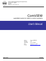
1
Faculty of Electrical Engineering and Computer Science
Smetanova 17, Maribor
Slovenia
I N S T I T U T E OF R O B O T I C S
ComVIEW
LabVIEW toolkit for DSP-2 control systems
User's Manual
Author :
Version:
LabVIEW
Date:
E-mail:
January, 2010
Darko HERCOG
1.5
8.5 or higher
January 11, 2010
[email protected]
ComVIEW
TABLE OF CONTENT
i
TABLE OF CONTENT
1. INTRODUCTION .............................................................................................................................................. 1 2. INSTALLATION AND COMPILING PROCESS ................................................................................... 3 2.1. 2.2. 2.3. COMVIEW INSTALLATION PROCEDURE ................................................................................................... 3 COMVIEW UNINSTALLATION PROCEDURE .............................................................................................. 4 VI COMPILATION ....................................................................................................................................... 4 3. VI CREATION PROCESS .............................................................................................................................. 6 3.1. 3.2. VI CREATION USING MATLAB/SIMULINK .............................................................................................. 6 VI CREATION WITHOUT USING MATLAB/SIMULINK ............................................................................. 7 4. DESCRIPTION OF VI TEMPLATE ............................................................................................................ 8 4.1. 4.2. FRONT PANEL ............................................................................................................................................. 8 BLOCK DIAGRAM ........................................................................................................................................ 8 5. VI EXECUTION ............................................................................................................................................... 11 5.1. INITIAL SETTINGS ................................................................................................................................... 11 5.2. VI EXECUTION ......................................................................................................................................... 13 5.3. DSP CONNECTION MANAGER ................................................................................................................ 14 5.4. DESCRIPTION AND USAGE OF COMVIEW MENUS ................................................................................ 16 Menu File ..................................................................................................................................................................... 17 Menu Operate .............................................................................................................................................................. 17 Menu Data ................................................................................................................................................................... 17 Variable Capture Window ........................................................................................................................................... 18 Window Set Decimation ............................................................................................................................................... 19 Window View DSP-2 Variables & Parameters ............................................................................................................ 20 6. LABVIEW WEB PUBLISHING TOOL AND REMOTE PANELS TECHNOLOGY ................................. 21 6.1. GUIDELINES FOR PREPARING REMOTE EXPERIMENTS ........................................................................... 22 7. LITERATURE.................................................................................................................................................... 24 FIGURES
ii
FIGURES
Figure 1: DSP-2 Rapid Control Prototyping System ..................................................................................................... 1 Figure 2: Installation programme for ComVIEW toolkit............................................................................................... 3 Figure 3: ComVIEW uninstallation programme ............................................................................................................ 4 Figure 4: ComVIEW compiling window ....................................................................................................................... 5 Figure 5: Procedure for replacing front panel object ..................................................................................................... 7 Figure 6: VI block diagram .......................................................................................................................................... 10 Figure 7: Initial settings ............................................................................................................................................... 11 Figure 8: Downloading executable code to the DSP-2 control system ........................................................................ 13 Figure 9: DSP-2 Start Up Information’s Window ....................................................................................................... 14 Figure 10: DSP Connection Manager Window ........................................................................................................... 16 Figure 11: ComVIEW menu ........................................................................................................................................ 16 Figure 12: Menu File ................................................................................................................................................... 17 Figure 13: Menu Operate ............................................................................................................................................. 17 Figure 14: Menu Data .................................................................................................................................................. 17 Figure 15: Variable Capture Window .......................................................................................................................... 19 Figure 16: Set Decimation Window............................................................................................................................. 19 Figure 17: Window DSP-2 Variables & Parameters.................................................................................................... 20 Figure 18: An example of virtual instrument, which can be remotely controlled using classical web browser .......... 22 Figure 19: login window .............................................................................................................................................. 23 CHAPTER 1: INTRODUCTION
1
1. Introduction
ComVIEW, a LabVIEW add-on toolkit, extends DSP-2 rapid control prototyping systems
(Figure 1) with the possibility for friendly user interfaces creation, online analysis, and by
using »Remote Panels« technology also remote control.
Figure 1: DSP-2 Rapid Control Prototyping System
Related DSP-2 documents
More information’s about DSP-2 controller can be found in DSP-2 User's Manual [1].
Programming of DSP-2 control systems by using MATLAB/Simulink is described in DSP-2
Library for Simulink User's Manual [3].
Chapter’s overview
Chapter 2 contains basic instructions about installation/uninstallation process and
compiling procedure of installed ComVIEW toolkit files.
CHAPTER 1: INTRODUCTION
2
In Chapter 3, creation of virtual instrument for individual DSP-2 application with or without
using MATLAB/Simulink is described.
Chapter 4 contains basic description of ComVIEW template virtual instrument.
In Chapter 5, detailed description of virtual instrument execution procedure is presented.
Chapter contains description of VI initial settings, binary code downloading processes,
meaning and usage of DSP Connection Manager window and description of run-time menu.
Chapter 6 describes possibility of remote control of LabVIEW virtual instrument using the
Web. Chapter includes instructions for remote experiments development that are based on
DSP-2 RCP systems.
CHAPTER 2: INSTALLATION AND COMPILING PROCESS
3
2. Installation and compiling process
2.1. ComVIEW installation procedure
After inserting CD into the CD unit, InstallShield installation programme for ComVIEW toolkit
will be automatically invoked (Figure 2). Installation programme will copy all toolkit files into
the C:\Program files\FERI\ComVIEW folder and updates LabVIEW search path. Prerequisite
for successful installation of mentioned toolkit is prior installation of LabVIEW 8.5 (or
above). If more than one versions of LabVIEW programme is installed on the PC, installation
process will update search path only for the latest version of LabVIEW.
CAUTION: after successful installation, all ComVIEW VI’s must be compiled. More about this
option is described in Chapter »VI compilation« on page 4. For normally operation of
ComVIEW toolkit, NI VISA drivers or VISA Run-Time Engine must be installed on the PC!
These drivers are freely available on the National Instruments Inc. home page (www.ni.com
> Support > Drivers and Updates).
BE AWARE: During the ComVIEW installation process, administrator privileges are required!
Figure 2: Installation programme for ComVIEW toolkit
CHAPTER 2: INSTALLATION AND COMPILING PROCESS
4
2.2. ComVIEW uninstallation procedure
In order to uninstall ComVIEW toolkit from the PC, select Add Remove Programs option in
Control Panel. In the list of installed programs, select ComVIEW and after that the button
Change/Remove. In dialog window, that will appear (Figure 3), select Remove option.
Figure 3: ComVIEW uninstallation programme
2.3. VI compilation
Before the first use of ComVIEW toolkit, all installed files must be compiled to the current
version of LabVIEW (installed files has been compiled using LabVIEW 8.5). Compilation
programme is available at Start > All Programs > FERI > ComVIEW > ComVIEW Mass
Compile (Figure 4). Compilation results will be stored in MassCompile.log file (C:\Program
files\FERI\comview).
CHAPTER 2: INSTALLATION AND COMPILING PROCESS
Figure 4: ComVIEW compiling window
5
6
CHAPTER 3: VI CREATION PROCESS
3. VI creation process
3.1. VI creation using MATLAB/Simulink
In the latest version of DSP-2 library for Simulink [3], LabVIEW virtual instrument for
selected Simulink model is automatically created during the code generation process, if
»Generate LabVIEW Virtual Instrument« option is selected in DSP-2 options. Generated VI
has the same name as the Simulink model (model.vi). If virtual instrument (model.vi)
already exists in the folder, VI creation/update process will automatically update VI front
panel. The numbers of front panel controls and indicators of automatically created VI depend
on the numbers of Simulink parameters (those that are selected as Tunable Parameters),
the numbers of DSP2_TT (DSP-2 To Terminal) and DSP2_FT (DSP-2 From Terminal) blocks
in Simulink model. For each such block or parameter, the following object on the VI front
panel is created:
•
Parameter: numerical control;
•
Blok DSP2_FT (DSP-2 From Terminal) : numerical control;
•
Blok DSP2_TT (DSP-2 To Terminal): numerical indicator;
Numerical controls represent DSP-2 input data. On control value change event, the newest
value is sent from the PC to the DSP-2 control system.
VI indicators serve for numeric
display of DSP-2 output data.
Automatically created front panel can be accommodated to the custom needs. If the user
wishes to change the front panel control or indicator, this can be done using the following
procedure: place the cursor on the front panel object (control or indicator), press the right
mouse button, in menu that appears select Replace (Figure 5) option and after that select
new object from the Controls palette.
BE AWARE: front panel objects can be only numerical scalar type!
CHAPTER 3: VI CREATION PROCESS
7
Figure 5: Procedure for replacing front panel object
3.2. VI creation without using MATLAB/Simulink
If the programming of DSP-2 control system is performed without using MATLAB/Simulink,
LabVIEW virtual instrument for selected application must be manually created. In windows
folder Start > All Programs > FERI >ComVIEW, ComVIEW template VI exists. Open this VI
and save it by different name (CAUTION: before first use, VI must be saved, otherwise some
errors will appear!). Created VI contains empty front panel and fully functional block
diagram. The users can place controls and indicators on the front panel and in such a way
accommodate front panel to the custom needs.
BE AWARE: front panel controls and indicators that will serve as input/output data for DSP-2
control system can be only numerical scalar type. These controls (indicators) must be, after
successful download procedure, »connected« with the appropriate DSP-2 variables. Detailed
description of this connection procedure can be found in Chapter 5.3
Manager) on page 14.
(DSP Connection
CHAPTER 4: DESCRIPTION OF VI TEMPLATE
8
4. Description of VI template
4.1. Front panel
Appearance of the VI front panel depends on the VI creation procedure. Detailed description
of the VI creation procedure exists in Chapter 3.1 (VI creation using MATLAB/Simulink) and
Chapter 3.2 (VI creation without using MATLAB/Simulink).
4.2. Block diagram
ComVIEW template block diagram (Figure 6) is composed out of two while loops. The upper
while loop must stay unchangeable, while the bottom while loop the user can modify to the
custom needs. VI block diagram contains the following functions:
•
Initialization (Init): the function Initialization is the first function that is executed
when the VI start button is pressed. In this function, the local/global variables and
events are initialized, message queues are created, run-time menu is added to the VI
front panel and an executable code download to the DSP-2 control system. Function
Init contains the user interface where some initial setting can be set. More about this
settings can be found in Chapter 5.1 on page 11;
•
Server: the function Message Server is »responsible« for the right transmission of
messages between the PC and the DSP-2 control system. This function performs the
following tasks: send/receive messages through the selected communication channel,
check/generates CRC code, decompose received messages and sends variables
values to the message queues, etc.;
•
Single Step: function Single Step must be placed inside the bottom while loop!
Function performs two important tasks:
o
In each while loop iteration, this function automatically update those front
panel indicators, that are connected via »DSP Connection Manager« (more
about DSP Connection Manager exists in Chapter 5.3 on page 14) with the
DSP-2 output variables.
Function generates matrix of all sampled variables. Each variable on the DSP-2 target has its
own identity number (ID number). Access to the individual sampled variable is possible by
using Index Captured Variable function. In this case, variable ID (numeric value) must be
connected to the second function input. Access to all sampled variables can be done using
Index All Captured Variables function. CAUTION: on the output of mentioned functions,
CHAPTER 4: DESCRIPTION OF VI TEMPLATE
9
matrix appears only, if variables are sampled (look sub chapter Window Variable Capture
inside Description and usage of ComVIEW Chapter.
•
Terminate (Term): the Terminate function is the last function that is executed, when
the user selects Stop option in Operate menu. This function releases all resources,
close communication channel, empty used stacks, etc.
CHAPTER 4: DESCRIPTION OF VI TEMPLATE
Figure 6: VI block diagram
10
11
CHAPTER 5: VI EXECUTION
5. VI execution
5.1. Initial settings
Before the first run, some initial settings that will grantee the right VI execution, must be
set. After a double click on the INIT function inside the VI block diagram (Figure 6), DSP-2
Init Config window (Figure 7) will appear.
Figure 7: Initial settings
DSP-2 Init Config window contains the following controls:
•
Communication Type: this option defines communication type between the PC and
the DSP-2 control system. Communication can be achieved using RS-232, USB or
ethernet.
•
Serial Settings: options inside Serial Settings section must be set, if »RS-232 or
USB« option is selected in Communication Type pop-up control.
CHAPTER 5: VI EXECUTION
o
12
Communication Channel: In Communication Channel pop-up menu, all
available communication channels on the user’s PC appears. Communication
channel, to which the DSP-2 control system is connected, must be selected.
CAUTION: options in this control appear only, if VISA driver or VISA Run-Time
Engine is installed on the PC. The latest version of NI VISA driver can be
downloaded from the National Instruments Inc. home page (www.ni.com).
o
Maximal Communication baud rate: this pop-up control contains available
communication baud rates.
•
Ethernet Settings: options inside Ethernet Settings section must be set, if »TCP/IP«
option is selected in Communication Type pop-up control.
•
o
Web Address: IP address of the DSP-2 system
o
Web Port: Web Port must be set to 14001.
Executable File Name: in Executable File Name edit box, the full path to the DSP-2
executable file (dsp2b.hex) must be entered. This file will be downloaded to the DSP2 system, immediately after the VI run button is pressed.
•
Set Trigger: if Set Trigger option is selected, the trigger and sampling process will be
automatically invoked, after the binary code starts executing on the DSP-2 target.
Capture and trigger initial settings can be set up inside the Capture & Trigger
Settings section.
•
Capture & Trigger Settings: this section is enabled, if Set Trigger option is selected.
Controls inside this section enable initial trigger and sampling settings. Section
includes the following controls: Trigger Source, Slope, Presamples, Decimation and
DSP Variables. The meaning of Trigger Source, Trigger Value, Slope, Presamples and
DSP Variables parameters is described in Chapter »Variable Capture« on page 18,
while the meaning of the Decimation parameter is described in sub Chapter Window
Set Decimation. During VI execution, capture and trigger parameter can be changed
inside the Variable Capture window (menu Data->Variable Capture).
•
Remote Panels: if virtual instrument VI will be remotely controlled via the Web
browser, then this option should be selected. More information’s about it can be
found in Chapter 6.
CHAPTER 5: VI EXECUTION
o
13
Allow remote user to stop the VI: if this option is selected, the remote user
can stop the VI execution (in this case, Stop option inside the Operate menu
is enabled).
o
Show login window: if this option is selected, then the login window will
appear (Figure 19), when the remote user takes control over the VI. In login
window the user must enter username and email address.
•
Global Settings:
o
Show download progress window: if this option s selected, download progress
window (Figure 8) will be shown during the binary code download process.
o
Show startup info window: if this option is selected, Start Up window (Figure
9) with some initial DSP data will appear on the PC, after the binary code
starts executing on the DSP-2 system.
o
Show Connection Manager window: this option defines, if DSP Connection
Manager window will be shown, after the binary code starts executing on the
DSP-2 control system. More about this option can be found in Chapter »DSP
Connection Manager« on page 14.
o
ComVIEW Instance ID: More than one instance of ComVIEW VI can execute at
the same time on the same PC. This parameter defines VI instance number.
This number must be different for each VI!
5.2. VI execution
When the VI is started, DSp-2 binary code is firstly downloaded to the DSP-2 control
system. The amount of currently transmitted data is shown in Downloading Progress
indicator inside Downloading executable code to the DSP-2 Controller (Figure 8) window.
Figure 8: Downloading executable code to the DSP-2 control system
14
CHAPTER 5: VI EXECUTION
When transmission completes, binary code automatically starts executing. At the same time,
DSP-2 Start Up Information’s (Figure 9) window appears on the user’s PC. This window
displays some basic DSP data and automatically disappears after a few seconds.
BE AWARE: when Show startup info window option inside the DSP-2 Init Config window
(Figure 7) is NOT selected, DSP-2 Start Up Information’s window will not show up!
Figure 9: DSP-2 Start Up Information’s Window
5.3. DSP Connection Manager
ComVIEW is an advanced LabVIEW toolkit, because the user does not need to wire front
panel objects terminals with the block diagram functions. These connections are performed
programmatically using LabVIEW references. This approach simplifies the VI usage, and at
the same time enables (automatic) graphical user interface creation.
When the binary code starts executing on the DSP-2 control system, DSP Connection
Manager (Figure 10) window appears on the PC. The Front Panel Controls list box contains
the list of all VI front panel controls, while the Front Panel Indicators list box contains the list
of all numerical VI front panel indicators.
The DSP Input Variables, DSP Parameters and
DSP Output Variables list boxes contain the names of all inputs, parameters and outputs of
DSP-2 control system.
CHAPTER 5: VI EXECUTION
15
BE AWARE: The names of inputs, outputs and parameters that appear in DSP Input
Variables, DSP Parameters and DSP Output Variables list boxes inside the DSP Connection
Manager window are retrieved from the DSP-2 target, therefore the content of these lists
depend on the binary code that is executing on the DSP-2 control target!
DSP Connection Manager enables the following definitions:
•
The value of which DSP output variable will be presented in which VI front panel
indicator;
•
The value of which DSP input variable or DSP parameter will be set with which front
panel control;
There are three connection options:
•
DSP input variable ‹−› front panel control,
•
DSP parameter ‹−› front panel control,
•
DSP output Variable ‹−› front panel indicator.
If one of the above mentioned couple is selected and one of the buttons (Add Input to
Connections, Add Parameter to Connections, or Add Output to Connections) is pressed,
selected couple is added to the Connection Table. When this action is performed, selected
control or indicator is deleted from the Front Panel Controls or Front Panel Indicators list
box. Individual couples can be deleted from the Connections Table list by using Delete
Connection button, while all connections in Connection Table list can be deleted by using
Clear all Connections button. When the OK button is pressed, DSP Connection Manager
window disappears, and the Connection Table list is stored to the connections.txt file. By
renewed VI execution, the Connection Table inside the DSP Connection Manager window is
initialized from connections.txt file if this file already exists.
If the VI is automatically created using the Simulink, then connections.txt file is
automatically created during the code generation/VI creation process.
BE AWARE: When option Show Connection Manager Window inside the DSP-2 Init Config
window (Figure 7) is NOT selected DSP Connection Manager Window will not appear!
16
CHAPTER 5: VI EXECUTION
Figure 10: DSP Connection Manager Window
5.4. Description and usage of ComVIEW menus
When the VI is started, VI menu (Figure 11) appears on the top of the VI front panel. This
menu is composed out of the File, Operate, Data and Help sub menus. In the following
sections, individual options inside these sub menus are described.
Figure 11: ComVIEW menu
17
CHAPTER 5: VI EXECUTION
Menu File
Menu File (Figure 12) contains only two options:
•
Save Control Values: when this option is pressed, the values of all front panel
controls will be stored in .ini file.
•
Load Control Values: values of all front panel controls are reinitialized to the values
that are retrieved from .ini file. New control values are also transmitted and updated
on the DSP-2 control system.
BE AWARE: If Remote Panel option inside the DSP-2 Init Config window is selected, then all
items inside the File menu are disabled!
Figure 12: Menu File
Menu Operate
Menu Operate (Figure 13) currently contains only Stop option. When this option or the
combination of »Control + .« keys is pressed, the virtual instrument will logically stop
executing.
BE AWARE: When Allow remote user to stop the VI in Remote Panels section, inside the
DSP-2 Init Config window (Figure 7) is NOT selected, then the Stop option is disabled!
Figure 13: Menu Operate
Menu Data
Menu Data (Figure 14) is the most usable menu during the VI execution. The following
subsections contain description of individual options in Data menu.
Figure 14: Menu Data
CHAPTER 5: VI EXECUTION
18
Variable Capture Window
By selecting menu Data > Variable Capture (Figure 14), Variable Capture window (Figure
15) will appear. This window contains Variable Capture and Trigger sections.
Variable Capture section contains the DSP Variables list box, where all DSP input and output
variables are listed and the Number of Samples, where the number of samples for each
variable can be set. Variables that we want to capture can be selected using one of the
following procedures:
•
Mouse click on the variable. To select more than one variable, hold the Control key
and use mouse click;
•
using arrow cursors and Space key;
Selected variables are sampled (the sampling period depends on the algorithm period and
the parameter Decimation) and store to the temporary memory on the DSP. When the
sampling process is finished, captured data is transmitted from the DSP to the PC. The
number of samples per variable depend Number of Samples parameter. In the current
version of ComVIEW toolkit this parameter is preset to 250.
In section Trigger, trigger parameters can be set. These parameters are:
•
Trigger Source: Trigger Source pop-up menu contains the list of all DSP-2 inputs and
outputs variables. Parameter Trigger Source defines trigger source;
•
Slope: parameter Slope defines the slope of trigger variable. Slope can be positive
(Rising Edge) or negative (Falling Edge);
•
Trigger Level: Trigger Level edit field defines the level of trigger variable, at which
the sampling is started;
•
Presamples: parameter Presamples defines the number of samples that we want to
capture, before sampling is started. Parameter Presamples must be less than
parameter Number of Samples!
•
Enable Trigger: with this button Enable Trigger se enables or disables Trigger
options;
BE AWARE: When Remote Panel option is selected inside the DSP-2 Init Config window
(Figure 7), Variable Capture window automatically closed after 60 seconds!
19
CHAPTER 5: VI EXECUTION
Figure 15: Variable Capture Window
Window Set Decimation
Using Set Decimation (Figure 16) Window, parameter Decimation can be set. This parameter
defines sampling period. If, for example this parameter is set to 10, that means, that all in
Variable Capture window selected variables are sampled each 10. interrupt service routine.
BE AWARE: When Remote Panel option is selected inside the DSP-2 Init Config window
(Figure 7), Decimation window is automatically closed after 15 seconds!
Figure 16: Set Decimation Window
CHAPTER 5: VI EXECUTION
20
Window View DSP-2 Variables & Parameters
By selecting View DSP-2 Variables & Parameters option in Data menu, Figure 17 appears
where all DSP variables and parameters are listed.
BE AWARE: When Remote Panel option inside the DSP-2 Init Config window (Figure 7) is
selected, option View DSP-2 Variables & Parameters in menu Data is not available.
Figure 17: Window DSP-2 Variables & Parameters
CHAPTER 6: LABVIEW WEB PUBLISHING TOOL AND REMOTE PANELS
TECHNOLOGY
21
6. LabVIEW Web publishing tool and Remote Panels technology
Using LabVIEW Web publishing tool, LabVIEW front panels can be quickly and effortlessly
publish on the Web. Once published, anyone on the Web with the proper permissions can
access and control the experiment without installing LabVIEW. LabVIEW Web publishing tool
automatically creates HTML document for selected LabVIEW virtual instrument (VI) and
store it, by default, to the LabVIEW WWW folder. When a remote viewer enters appropriate
URL address, the LabVIEW front panel appears in the Web browser. Once connected to the
remote experiment, the client connection is automatically in a monitor state. If another
client is controlling the remote experiment, the remote client is able to monitor the actions
of the controlling client. To request control of the program, right click on the front panel and
selection of Request Control is required. If another client has control, the controlling client is
notified that control time has now become limited. Once the timeout occurs or the
controlling client released control, application control is automatically switched to the
requesting client. Once the user granted control, GUI controls become active and running
the LabVIEW application is like running the application from the local environment.
More information’s about LabVIEW Web publishing tool can be found on National
Instruments Inc. home page (www.ni.com)
Using described software and DSP-2 control hardware, “DSP-based remote control
laboratory” has been realized. This remote laboratory is accessible on the following Web
page: www.weblab.si.
CHAPTER 6: LABVIEW WEB PUBLISHING TOOL AND REMOTE PANELS
TECHNOLOGY
22
Figure 18: An example of virtual instrument, which can be remotely controlled using classical web
browser
6.1. Guidelines for preparing remote experiments
When the virtual instrument will be remotely controlled, these initial settings are
recommended (Figure 7):
•
Remote Panel: this option should be selected. In this case, some additional
mechanism is turned on, which reinitialize all front panel controls to their default
values (caution: before the first run, default values for all front panel controls must
be set) when the remote users change. If, additionally »Show login window« option
is selected, login window will appear when the remote user gain control (Figure 19).
CHAPTER 6: LABVIEW WEB PUBLISHING TOOL AND REMOTE PANELS
TECHNOLOGY
•
23
Global settings: switches Show start up information’s and Show Connection Manager
should be turned of. For example in the case of power supply problem, experiments
must autonomously reinitialize to the initial state, without administrator intervention.
Figure 19: login window
CHAPTER 7: LITERATURE
24
7. Literature
[1] Milan Čurkovič, “DSP-2 User's Manual”, Institute of robotics, Faculty of Electrical
Engineering and Computer Science, University of Maribor.
[2] Evgen Urlep, “DSP Terminal User's Manual”, Institute of robotics, Faculty of Electrical
Engineering and Computer Science, University of Maribor.
[3] Darko Hercog, “DSP-2 Library for Simulink User's Manual”, Institute of robotics,
Faculty of Electrical Engineering and Computer Science, University of Maribor.
[4] LabVIEW 8.5 User's manual (www.ni.com)