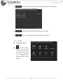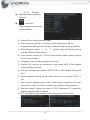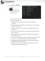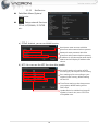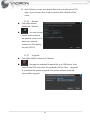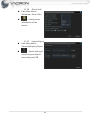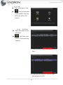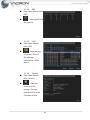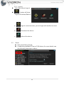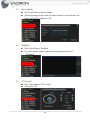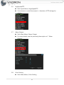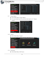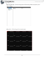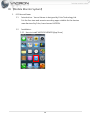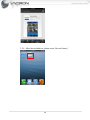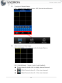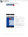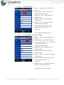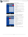
1
8CH NVR User’s Manual 2014 JAN V1.0 Notice before use This authorization agreement of client’s software/hardware is legally effective to you(individual or single machine) and our company. This agreement covers components of software/hardware, media, print, online publication and electronic files. All the application through installation, duplication or the other way must be based on this agreement. If you disagree with the terms of this agreement, please don’t install or use this product. This product is protected by copyright law, international copyright treaties and other international property laws and treaties. Please note this product authorizes to you, not sold. Through the software/hardware license code on the license certificate indicates you have got the permit of use. Copyright The company owns all the headers, including but not subject to the copyright, software/hardware products and any duplicates. The company reserves all the rights not expressed clearly. Unsecure notes The company clearly denies warrantee repairmen of any products. Unsecure of warrantee for any kind of expressed or implied, including any documents and software products of no limit, implied warrantee repairmen or marketability, suitable for specific usage or non-infringement. Terms and Conditions The overall risk, is that arising out of the use or performance of software and hardware products. This product will be informed, such as when it is used with certain device or other hardware, may enable you to carry out surveillance and data processing, which may be subject to or in violation of applicable law, which includes but is not limited to data privacy, and criminal law. Please check your use to comply with applicable laws is the responsibility of users themselves. Limitation of liability The provision of this paragraph is in effect to the maximum extent permitted by applicable law. In any situation Xia, VACRON or its dealer assumed any special, and accidentally of, and indirect of, and or any indirect loss (including but not limited to business profits loss, and business interrupted, and commercial information loss, and or any other money loss of compensation) due to using or cannot using of software products or provides or failed provides appropriate of support, even we of company has is informed this class damage of possibilities. If there is no willful misconduct or gross negligence, under any provision of this agreement, VACRON total liability, shall be limited to the amount actually paid. Other conventions (A) Prohibition of reverse engineering, decompilation, splitting or rescind the contract within the scope allowed by the applicable law cannot be waived by, as well as any software and hardware components of the product. (B) As long as the recipient agrees to the terms of this agreement, you may permanently transfer rights of use of this product. Closing remarks Without prejudice to any other rights, the company may terminate this license agreement. If you fail to comply with its terms and conditions, in which case you must destroy all copies of the software product CONTENTS Foreword 【Notices】 ............................................................................................................................. 1 I. 【Function illustrate】 ....................................................................................................... 2 1. System Login ............................................................................................................ 2 2. Screen function ....................................................................................................... 4 3. Quick Menu .............................................................................................................. 8 3.1 Main Menu ................................................................................................... 8 3.1.1 Record ............................................................................................................ 8 3.1.2 System......................................................................................................... 13 3.1.3 Advanced ................................................................................................... 27 3.1.4 Info ............................................................................................................... 33 3.2 Guide ........................................................................................................... 35 3.3 Record Mode............................................................................................ 36 3.4 PlayBack ..................................................................................................... 36 3.5 PTZ Control ............................................................................................... 36 3.6 HighSpeedPTZ ......................................................................................... 37 3.7 Alarm Output ........................................................................................... 37 3.8 Color Setting ............................................................................................ 37 3.9 Output Adjust .......................................................................................... 38 3.10 Logout......................................................................................................... 38 3.11 Full Screen ................................................................................................. 38 II. 【NET Surveillance WEB IE】 ........................................................................................40 III. 【Mobile Monitor System】 .........................................................................................46 1. iOS VacronViewer .................................................................................................46 2. Android Vacron Viewer ......................................................................................57 Foreword 【Notices】 WARNING Do not expose the DVR under the sunlight, heat or wet environment while installation. As it could decrease the performance of DVR and damage the machine. Do not touch the power plug or case with wet hands as this could result electric shock. Do not forcedly bend or put heavy object on power cable as this could result in injury to personal or equipment. Do not operate with damaged power cord or loose electrical outlet as this could result in electric shock or accident. Please use individual power instead of share electrical outlets with other electrical equipment as this could result in damage or accident. Do not attempt to service this DVR by yourself as it may expose you to dangerous voltage or other hazards. Please refer all service to the qualified servicing distributor. Please do not remove the machine housing during operation. It may cause electric shock or accidental injury. CAUTION Do not place the machine on an uneven surface or it would decrease the DVR efficiency or malfunction. Avoid any shock or bumping of the DVR while recording. Improper handling could damage the system. CAUTION Make sure the voltage selector switch is set to appropriate setting before plug in! 1 I. 【Function illustrate】 1. System Login After enter system, the Configuration Wizard will help you to configure all parameters of IP Cam and DVR (Figs 1). (Figs 1) Press Next or Cancel. It will return to split screen; Press Next, the system will generate a list of IP cam or DVR that are found and connected to the network (Figs 2). (Figs 2) 2 Press OK, system will auto configure and show image of IP cam or DVR(Figs 3). (Figs 3) After complete configuration, system will show multiple split screens. Press the right button on the mouse, system will show Quick Menu or Main Menu(Figs 4) (Figs 4) 3 The Default login name: admin, password: (NONE) (Figs 5). (Figs 5) 2. Screen function 2.1 Operate Split Screen (Figs 6) (Figs 6) four channels viewing single channel viewing nine channels viewing eight channels viewing full screen channel Split Screen turn to previous page Split Screen turn to next page Display all channels, click it will show all channels Disable all channels, click it will disable all channels Record, click it will record for all channels Stop record, click it will stop record for all channels 4 2.2 2.2.1 Channel Set Click each channel will setup IP Cam or DVR. Click the channel list on the left side, choose a channel then press the right button on the mouse will show Set Up. Click Setup will show Digital Channel as Figs shows below Digital Channels: Select the IP Cam or DVR which you want to connect when enter Digital Channels, click “Add” will enter Remote access configuration 5 2.2.1.1 Remote access configuration:It can assist you in searching all available IP Cam or DVR, as Figs shows below 1) Click “Search” will show all available IP Cam or DVR and all relative data when enter Remote access configuration. 2) Click the IP Cam or DVR that you wish to connect from the list of all items. Click OK will return to Digital Channels 6 3) Click the channel you want to show and press “OK”. 4) It will show live viewing 7 3. Quick Menu Press the right button on the mouse and choose Main Menu. 3.1 Main Menu Path:Quick Menu /Main Menu 3.1.1 Record Path:Main Menu/ Record :Record. Divided into Record Conf/ PlayBack / Backup 8 3.1.1.1 Record Conf Path:Main Menu/ Record/Record Conf :Configure the recording time. a c b d a) d Channel: click drop down menu of channel. You can setup single channel or all channels; the default setup will be channel 1. b) RAID: you can copy all data to another when you connect two HDD; the default setup will be “uncheck”. c) Length: setup recording time, least 1 min., limit 120 min.; the default setup will be 60 min. d) Mode: Schedule, Manual, Stop, click “Schedule” , you can choose Monday to Friday or all to setup mode and time of record in the week drop menu. There are 4 time options for you to choose. Select “Manual”, it will record 24hrs when the record mode is manual and will be normal recording. ; Select “Stop”, it will not recording ; the default setup will be Set up. 9 3.1.1.2 PlayBack Path:Main Menu/ Record / PlayBack : Search for and playback recorded video files. c a b a) Playback button Select date and play channel then click play, it will start playback. Pause Pause the video Rewind Rewind play video Stop Stop video playback Slow Playback Fast rewind Fast forward pause rewind button Video will play slowly with 1X, 2X, 3X, 4X speed. To go back normal speed, just press play button again. Video will fast rewind with 1X、2X、3X、4X speed. To go back normal speed, just press play button again. Video will fast forward with 1X、2X、3X、4X speed. To go back normal speed, just press play button again. Press Pause and click it then will play rewind one page each time pause playback Press Pause and click it then will play forward one page each button time Rewind to last file Next file Rewind to the previous hour and play back the files Playback next hour files 10 Press “Repeat Loop Play” will become Repeat button repeat loop play. Press Full screen, the image will be largest and press again will Full screen go back to normal. scissors button USB button Press , same file will be Press Cut will become . Selecting how long you want and press again . It will back up the file which you cut. This function will be used when you use Cut function. It can copy to USB to switch to time page, press again will back to date page. b) Time bar shows green means normal record; red means alarm record; yellow means manual record; it will playback according to your setting. The default set up will be all check. Check this function and press pause then will be Sync; if uncheck, there is only a single channel effect. You can select a more precise playback time for current view, select 24 hours, 2 hours, 1 hour, 30 minutes; the default setting will be 24 hours. c) It will shows sub menu when you press the right button on the mouse. UpWindow: click this will back to “Record” function page. Stop Playing: click this will stop play. Full Screen: click this will pull the screen to the largest and press the right button on the mouse will back to normal. 11 3.1.1.3 Backup Path:Main Menu/ a b c d e Record / Backup : Backup files to backup device. Detect:Click “Detect” when you insert USB flash memory. a) It will research USB device again and show it on the screen if detect it. b) Backup:Click “Backup” it will shows page. ❶ ❷ ❸ ❹ ❺ ❻ ❼ 1) Type: All, Sensor, motion detect, alarm all, manual, normal; default setting will be All. 2) Channel: select the channel that you want to backup. From channel 1 to channel 8; default setting will be Channel 1. 3) Start time: set up start time for backup. 4) End time: set up end time for backup. 5) Remove: clear all files. 6) Add: add type or channel which you select. 7) Backup format: H.264 and AVI; default setting will be H.264. 12 c) Burning: click it will shows, Burning will synchronous record channel 1 to channel 8 to USB device. d) Erase: format the USB device which you select. e) Stop: it can be stopped format when you click it. 3.1.2 System Path:Main Menu/ System :System config. Divided into General/ Network/ NetService / GUI Display/ RS485 Device/ RS232/ Tour/ Digital 13 3.1.2.1 General Path:Main Menu/System/ General :Configure Time,language and remote control address. a) System Time: setting time and date. b) Date Format: yy/mm/dd, mm/dd/yy, dd/month/year. It will be displayed according to the changes; default setting will be yy/mm/dd. c) Date Separator: select ‘-“ or “/” symbol, date will display as your desired ; default setting will be ‘-“. d) Time Format: choose 24 / 12 hour time format; default setting will be 24 hour time format. e) Language: there are 28 languages for set up. f) Storage Full: setting up overwrite or stop when HDD is full; default setting will be overwrite. g) DVR No.: setting up numbers of DVR, enter 0~998; default setting will be 0. h) Video standard: setting up the video format, you can select NTSC or PAL. i) Auto Logout: Setting logout time. It will require a password to enter main menu, enter 0~60 min, 0 means none; default setting will be 0. j) Machine Name: Setting up name of DVR. Maximum 32 characters; default setting will be LocalHost k) DST: Set date and day of week, it will add 1 more hour to time. 14 3.1.2.2 Network Path:Main Menu/System/ Network :Setup network parameters: IP address, subnet mask etc… a) Net Card: Wire Net Card. b) DHCP: Auto IP search. c) IP address: IP for the network device; default setting will be 192.168.1.9 d) Subnet Mask: Subnet Mask for the network device; default setting will be 255.255.255.0 e) Gateway: Gateway for the network device; default setting will be 192.168.1.1 f) Primary DNS: Primary DNS for the network device; default setting will be 168.95.1.1 g) Secondary DNS: Secondary DNS for the network device; default setting will be8.8.8.8 h) TCP Port: Port for IE and Smart Phone; default setting will be 34567 i) HTTP Port:HTTP Port for IE; default setting will be 80 port. j) HS download: check it will set up only for High speed download; default setting will be unchecked. k) Transfer Policy: Auto adjust, Quality prefer, Fluency for choose; default setting will be Quality prefer. 15 3.1.2.3 NetService Path:Main Menu/System/ NetService :Setup network Services: PPPoE, NTP, EMAIL, IP FILTER etc… a) PPPoE: Enabled , you can use PPPOE function User Name: enter account which be given from telecommunication operator. Password: enter password which be given from telecommunication operator. IP address: it will reboot after enter the IP address and will display IP address after reboot. b) NTP: You can use the NTP function after enable. Server IP: setting up location of NTO according to your request in the country. Port: setting up Port according to your request in the country; default setting will be 123. Time Zone: setting up the time zone as you request; default setting will be GMT+8:00 Update Period: to decide how long will update it, least 0 min, max. 65535 min will update once. 16 c) EMAIL: You can use Email function when you check it. ❶ ❷ ❸ ❹ ❺ ❻ ❼ ❽ 1) SMTP Server: enter SMTP of the mail. For example, gamil will enter 2) 3) 4) 5) 6) 7) 8) 9) smtp.gmail.com; default setting will be Your SMTP Server. Port: enter Port of the mail. For example, gamil will enter 465; default setting will be 25. Need SSL: if mail box support this function that you must check. For example, gamil must check; default setting will be uncheck. User Name: enter box account of mail. Password: enter password of mail box. Sender: enter Sender. Receiver: enter receiver’s mail account. Title: the subject will display after you mail; default setting will be Alarm Message. Complete setting, press OK, will go back to EMAIL setting page, you can do mail testing to make sure all correct. d) IP EILTER: You can use this function after enable. Restricted Type: you can choose blacklist or whitelist. Blacklist: It will disable for remote monitor after add IP address. Whitelist: It will disable for remote monitor after add IP address. To erase IP, check the IP address and click delete, the IP will be deleted. 17 e) DDNS : This function will be enabled to operate after check it. DDNS Type: CN99、DynDns、Oray、 NO-IP、MYQ-SEE, five types; default setting will be CN99. User Name: enter register account of DDNS User Name: enter register account of DDNS f) FTP: This function will be enabled to operate after check it. 1) Server IP: enter IP address of Server of FTP. 2) Port: enter Port of FTP; default setting will be 21. 3) User Name: enter user name of valid user of FTP. 4) Password: enter password of valid user of FTP. Anonymous: wouldn't need to enter User Name and Password after check it. 5) Max File Length: enter upload maximum limit of the file size, minimum 0 and maximum 65535; default setting will be 128 trillion. 6) DirName: upload files to the FTP. g) ARSP: Enter server of ARSP; default setting will be disable. 18 h) Alarm Server: This function will be enabled to operate after check it. 1) Protocol type: GENERAL 2) Server Name: Enter IP of Server or Domain Name; default setting will be AlarmServer. 3) Port: enter Port of Alarm server; default setting will be 15002. 4) Alarm report: will upload massage of alarm after check it; default setting will be check. 5) Log report: will upload the massage of log after check it; default setting will be disable. i) Wireless Config: will be able to connect to network via USB 3G SIM card after check it. 19 1) Type: Auto、TD-SCDMA、WCDMA、CDMA1.X、GPRS、EVDO; default will be EVDO. 2) Wireless AP: enter wireless AO of 3G SIM card; default will be ChinaNet. 3) Dial Number: enter dial number of 3G SIM card; default setting will be #777. 4) User Name: enter user name of 3G SIM card. 5) Password: enter password of 3G SIM card. 6) IP Address: will display IP after enter correctly and connect to network j) Mobile Monitor: Smart phone will enable for remote monitor after check it; default setting will be Enable. Port: enter Port for Smart phone monitor; default setting will be 34599. k) UPNP:It will don’t need a port for remote monitor via IE when using router. It will operate when router has this function; default setting will be disable. 20 l) Wifi: connect USB Dongle will be able to connect to WIFI after check; default setting will be disable. DHCP: IP will auto assign after check. SSID:the Name of WiFi device. Password: the connecting password for WiFi device. IP Address: IP of WiFi device; default setting will be 192.168.1.12 Subnet Mask: Subnet Mask of WiFi device; default setting will be 255.255.255.0 Gateway: Gateway of WiFi device; default setting will be 192.168.1.1 m) RTSP: For RTSP function; default setting will be disable. Port: will need to enable Port if you use router. Thus you will be able to remote monitor when using a non-IE browser. n) Cloud: Will be able to use this service when you check it. Cloud: will be able to use this service when you check it. MTU: enter Byte of MTU; default setting will be 1280. 21 3.1.2.4 GUI Display Path:Main Menu/System/ GUI Display :Settings for GUI and monitoring parameters a) Channel Title: change the name for current selected channel. b) Time display: Live view wouldn’t display time when uncheck it; default setting will be check. c) Channel Title: Live view wouldn’t display title when uncheck it; default setting will be check. d) Record Status: Live view wouldn’t display record status when uncheck it; default setting will be check. e) Alarm Status: Live view wouldn’t display alarm icon when uncheck it; default setting will be check. f) Deflick : will reduce seismic for video. It will asking for reboot after you disable; default setting will be check. g) Bitrate info: display all channels’ bitrate. h) Transparency: adjust bar for transparency, minimum 128, maximum 255. i) Resolution: the resolution of VGA and HDMI can be adjusted. Use the screen of VIDEO and decrease resolution when VGA can’t be displayed; use the screen of VGA or VIDEO and adjust increase resolution when the HDMI can’t be displayed. System will claim to reboot after resolution has be adjusted. 22 3.1.2.5 RS485 Device Path:Main Menu/ System/RS485 Device :PTZ Config a) Protocol: there are 16 protocols for selection; default setting will be NONE. b) Address: setting address of PTZ; default setting will be 1. c) Baudrate: there are 8 speeds for selection; default setting will be 9600. d) Data Bits: there are four types for selection; default setting will be 8. e) Stop Bits: there are two types for selection; default setting will be 1. f) Parity: there are four types for selection; default setting will be None. 3.1.2.6 RS232 Path: Main Menu/System/ RS232 :Settings for Serial port function and baud rate. a) Function: There are five functions for setting; default setting will be NONE. 23 b) Baudrate: there are 8 speeds for selection; default setting will be 115200. c) Data Bits: there are four types for selection; default setting will be 8 d) Stop Bits: there are two types for selection; default setting will be 1. e) Parity: there are four types for selection; default setting will be None. 3.1.2.7 Tour Path: Main Menu/System/ Tour :Setting for touring parameters. a) Enable tour: tour function can be used check; default setting will be disable. b) Interval: setting how long for tour once, at least 5 seconds, maximum 120 seconds; default setting will be 5s. c) Single channel: setting single channel of tour; default setting will be all open. d) Four channel: setting four channels of tour; default setting will be all open. e) Eight channel: setting eight channels of tour; default setting will be all open. f) Nine channels: setting nine channels of tour; default setting will be all open. g) Interval: setting how long for alarm tour once, at least 5 seconds, maximum 120 seconds; default setting will be 5s. h) Return after finished: return to live view after alarm finished. 24 3.1.2.8 Digital Path: Main Menu/ System/Digital :Set channel mode, and digital channel parameter settings. a) Digital channels Path: Main Menu/System/ Digital/Digital channels : Setting record source that come from which channel of IPCAM or DVR. 1) Channel: it can set up individual from channel 1 to 8 or set up all together. 2) Enable: set up for digital channel when you check; default setting up will be disable. 3) Time synchronization: time for each connected to IPCAM or DVR can be set up the same as system when you check. 4) Decode order: choose your preferences of network, Resolution Priority, Middle, Viewing fluency; default setting will be middle. 5) Connection Mode: there are “single connection” and “multi connection” models, it can connect to multiple IPCam or DVR devices when choose multi connection and will display via tour; default setting will be single connection. 6) Add: searching for currently available IP cam or DVR devices. 25 Click “add” function from “Digital channel” will enter “Remote access configuration; click “Search” will show the data with currently available IP cam or DVR devices and select these devices which you want to connected. Configur name: you can change the name of the connection device; default setting will be chConfig01. Device Type: setting the type of the device, three types which are IPC, DVR, HVR; default setting will be IPC. Protocol: there are two types NETIP or ONVIF; default setting will be NETIP. IP channel: setting from 0~65535 Device address: displays the current IP address of the selected device. Port: displays the current Port of the selected device Username: enter username of IP Cam or DVR; default setting will be admin. Password: enter password of IP Cam or DVR; default setting will be empty. 7) Delete: eliminating IP CAM or DVR devices from the network list. 26 b) Channel status Path: Main Menu/System/ Digital/ Channel status : Display all connected channels’ status. c) Channel Type Path: Main Menu/System/ Digital/ Channel Type : Setting resolution of cameras. Choosing channel type according to the resolution and playback that you want to set up. 3.1.3 Advanced Path: Main Menu/ Advanced : Setting System Tools. 27 3.1.3.1 Storage Manage Path: Main Menu/ Advanced / Storage Manage :HDD date management. a) Read/Write: setting HDD to be Read/Write. b) Read only: setting HDD can be read only. c) Redundant: 2 HDD will have same data. This function can be used only have 2 HDD. d) Format Storage: format HDD. e) Recover: reappear the error. f) Partition: to split HDD into multiple pieces. 3.1.3.2 Account Path: Main Menu/ Advanced / Account :User Manager. a) Modify account: add or make changes to an existing account. b) Modify group: will add or make changes to an existing group. c) Modify password: add or make changes to an existing password. d) Add User: add a new user. e) Add Group: distinction made by group account f) Delete User: delete an existing user. g) Delete Group: delete an existing group. 28 h) Update: click Update after finished adding, modifying groups or unchanged. 3.1.3.3 Online User Path: Main Menu/ Advanced / Online User :It will shows current online users, IP and login type. 3.1.3.4 Output Adjust Path: Main Menu/ Advanced / Output Adjust :Output image setting adjustment and brightness, contrast, saturation, hue adjustment. a) Top Deflate: upper boundary of VIDEO, VAG and HDMI can be adjusted via adjust. b) Bottom Deflate: lower boundary of VIDEO, VAG and HDMI can be adjusted via adjust bar, the value from 0 to 100; default setting will be 0. 29 c) Left Deflate: left boundary of VIDEO, VAG and HDMI can be adjusted via adjust bar, the value from 0 to 100; default setting will be 0. d) Right Deflate: right boundary of VIDEO, VAG and HDMI can be adjusted via adjust bar, the value from 0 to 100; default setting will be 0. e) Display settings: there are VGA/HDMI and TV three options; default setting will be VGA/HDMI. f) Brightness: the brightness of TV, VGA, HDMI can be adjusted via adjust bar, the value from 0 to 100; default setting will be 54. g) Contrast: contrast of TV, VGA, HDMI can be adjusted via adjust bar, the value from 0 to 100; default setting will be 54. h) Saturation: saturation of TV, VGA, HDMI can be adjusted via adjust bar, the value from 0 to 100; default setting will be 50. i) Hue: hue of TV, VGA, HDMI can be adjusted via adjust bar, the value from 0 to 100; default setting will be 50. 3.1.3.5 Auto Maintain Path: Main Menu/ Advanced / Auto Maintain :Setting time for auto maintain, auto reboot system and whether automatically delete old files. a) Auto-Reboot System: there are nine auto-reboot system models which are close, everyday, Sunday, Monday, Tuesday, Wednesday, Thursday, Friday, Saturday. System will request the time for auto-reboot system when you choose everyday or Monday to Sunday. ; it will not auto-reboot system when you choose close, if you want to reboot system that you must manually reboot; default setting will be auto reboot system at 1;00 AM. 30 b) Auto Delete: you can auto delete files from one day ago to 255 days, if you choose close it will not delete files; default will be close. 3.1.3.6 Restore Path: Main Menu/ Advanced / Restore :You can choose restore options which are general, record conf., alarm set, network, netService, GUI display, account, RS232. 3.1.3.7 Upgrade Path: Main Menu/ Advanced / Restore :Storage the updated firmware file on a USB device, then insert to the DVR and select the updated F/W file, click “Upgrade” to complete the system upgrade, the system will automatically reboot after upgrade. 31 3.1.3.8 Device Info Path: Main Menu/ Advanced / Device Info :Setting some information of the device. 3.1.3.9 Import/Export Path: Main Menu/ Advanced/Import/Export :Export setting of current log and import new setting via USB. 32 3.1.4 Info Path: Main Menu/ Info : Check information of the system. There are HDD info., BOS, LOG, Version. 3.1.4.1 HDD Info Path: Main Menu/ Info / HDD Info :HDD Info: time period, , the remaining capacity. a) View recording times: View the recording time. b) View type and capacity: View the type and capacity of HDD. 33 3.1.4.2 BPS Path: Main Menu/ Info /BPS :View the BOS of the system. 3.1.4.3 LOG Path: Main Menu/ Info /LOG :View the log of system. Record the relevant information of the device. 3.1.4.4 Version Path: Main Menu/ Info /Version :View the version of the system. You can view the ID and the Firmware of the 34 3.1.5 Logout Path: Main Menu/Logout :System will show Logout/Shutdown/Reboot. 3.2 a) : Logout current account, you can login with another account. b) : Shutdown the device. c) : Reboot the device. Guide Path: Quick Menu/Guide Configuring available IPCam or DVR device, for more details, see the previously description above. 35 3.3 Record Mode Path: Quick Menu/ Record Mode Quickly setting record mode for each channel or all channels, the mode will be Set / Manual / Off. 3.4 PlayBack Path: Quick Menu/ PlayBack For more details, please see the previously description of “PlayBack”. 3.5 PTZ Control Path: Quick Menu/ PTZ Control Setting for PTZ. 36 3.6 HighSpeedPTZ Path: Quick Menu/ HighSpeedPTZ Use mouse to control the camera’s direction of PTZ during the display. 3.7 Alarm Output Path: Main Menu/ Alarm Output For more details, see the previously description of “Alarm Output”. 3.8 Color Setting Path: Main Menu/ Color Setting 37 3.9 Output Adjust Path: Main Menu/ Output Adjust For more details, see the previously description of “Output Adjust”. 3.10 3.11 Logout Path: Main Menu/ Logout For more details, see the previously description of “Logout”. Full Screen Path: Main Menu/ Full Screen 38 Enlarge to full screen. 39 II. 【NET Surveillance WEB IE】 Login IE browser After Keyin IP or DDNS, if password without setting in DVR device, just key in “admin” for login. After login, a message pops out to choose the monitor streams for main stream or subsidiary stream, default value is subsidiary stream. 40 After login, monitoring images and select 1/4/9 screens. Playback : Setting requested period of time to playback. 41 Alarm Log: Login in and then can search Alarm log messages. Device Config:Setting the record selections. 1) Record: 42 2) Alarm settings:Setting the alarm selections. 3) System settings:Setting the system selections. 43 4) Advanced:Setting the Advanced selections. 5) Info:Checking HDD information, Log, current version & device No. 44 Config Manager:Set the storage place for Recording Videos and photos, and alarm setting. Log Out:Click to log out for current screen. 45 III. 【Mobile Monitor System】 1. iOS VacronViewer 1.1 Introduction:VacronViewer is designed by Fuho Technology Ltd. It is the live-view and remote recording apps suitable for the devices manufactured by Fuho, brand name VACRON. 1.2 Installation: 1.2.1 How to install VACRON VIEWER [App Store] 46 1.2.2 Into “App Store” and search for “vacron” , user will find [VacronViewer] 1.2.3 Click [VacronViewer], user will see introduction and version information, please press FREE and beginning to download the apps. 47 1.2.4 After the installation, please enter [VacronViewer] 48 1.3 Function of VacronViewer: 1.3.1 There are three major options: LIVE, Device List and Records. 1.4 How to see Live View Image: 1.4.1 [LIVE VIEW]:Live view channels of selected Device. 1.4.2 [Split Window]:Single, 4-split, 9-split (default). Single channel: double click to display selected channel. 4 Split Channel: show #1~4 live view channels. 9 Split Channel: show #1~9 live view channels. 49 1.4.3 [Snapshot]: choose channel and yellow frame will appear. Press PIC to take snapshot. 1.4.4 [Recording]:choose channel and yellow frame will appear. Press REC to recording. 1.5 PTZ Function: support for DVR only 1.5.1 1.5.2 1.5.3 :Control the direction of PTZ :Auto Pan. :Preset PTZ camera viewing point 1~16 on DVR, when user press GoTo, camera to turn to the preset point. 1.5.4 Zoom: Zoom In & Out. 1.5.5 Focus: PTZ camera focus. 1.5.6 Diaphragm : PTZ camera diaphragm adjustment. 50 1.6 Device List:Add/ Change Device setting. 1.6.1 Add:Press [+] to add new device on apps. 1.6.1.1 Add DX-DVR series to apps. a) Name: Assign a remark name for the device. b) Host Address:Key in the device IP address or Domain name. c) Media Port:Key in DX-DVR media port. a. Default: 34567 b. d) Cmd Port:Key in DX-DVR media port. c. Default: 34567 d. e) Account:key in User name of DX-DVR. e. Default user name: admin. f. f) Password: key in password of DX-DVR, please keep blank if there’s no password. Press DONE to finish the setting. 51 1.6.1.2 Add DVR device a) Name: Assign a remark name for the device. b) Host Address:Key in the device IP address or Domain name. c) Media Port:Key in DVR media port. a. Default: 9000 b. d) Cmd Port:Key in DVR media port. c. Default: 8000 d. e) Account:key in User name of DVR. Default user name: admin. e. f) Password: key in password of DVR, f. please keep blank if there’s no password. Press DONE to finish the setting. 1.6.1.3 Add 3G MDVR to Vacron Viewer a) Name: Assign a remark name for the device. b) Host Address:Key in the IP address or Domain name of 3G server. (ex. Taipei 3G Server Domain Name : a. taipei3g.mobilekore.com) b. c) Media Port:Key in DVR media port. c. Default: 24680 d. d) Cmd Port:Key in DVR media port. Default: 24681 e. e) Account:key in User name of 3G server. f. (ex: Demo bus). g. f) Password: key in password of 3G server, please keep blank if there’s no password. g) Vehicle ID:Key in Vehicle ID and press DONE to complete the setting. Press DONE to finish the setting. 52 1.6.1.4 Add IP Camera to Vacon Viewer a) Name: Assign a remark name for the device. b) Host Address:Key in the IP address or Domain name. c) Media Port:Key in IP camera media port. a. Default: 80 b. d) Cmd Port:Key in IP camera media port. c. Default: 80 d. e) Account:key in User name of IP camera, e. default user name: admin. f. f) Password: key in password of IP camera, please keep blank if there’s no password. Press DONE to complete the setting. 1.6.1.5 Add TI series NVR (TI-NVR) to Vacron Viewer a) Name:Assign a remark name for the device. b) Host Address:Key in the IP address or Domain name. c) Media Port:Key in NVR media port. a. Default: 8080 b. d) Cmd Port:Key in NVR media port. c. Default: 80 d. e) Account:key in User name of NVR, e. default user name: admin. f. f) Password: key in password of NVR, please keep blank if there’s no password. Press DONE to complete the setting. 53 1.6.1.6 Add NVR PC200 to Vacron Viewer a) Name:Assign a remark name for the device. b) Host Address:Key in the IP address or Domain name. c) Media Port:Key in NVR media port. a. Default: 5566 b. d) Cmd Port:Key in NVR media port. c. Default: 80 d. e) Account:key in User name of NVR, e. default user name: admin. f. f) Password: key in password of NVR, please keep blank if there’s no password. Press DONE to complete the setting. 1.6.1.7 Add LEX to Vacron Viewer: a) Name:Assign a remark name for the device. b) Host Address:Key in the IP address or Domain name. c) Media Port:Key in NVR media port. a. Default: 5577 b. d) Cmd Port:Key in NVR media port. c. Default: 5566 d. e) Account:key in User name of NVR, e. default user name: admin. f. f) Password: key in password of NVR, please keep blank if there’s no password. Press DONE to complete the setting. 54 1.6.1.8 Add NK100 to Vacron Viewer a) Name:Assign a remark name for the device. b) Host Address: Key in the IP address or Domain name. c) Media Port:Key in NVR media port. a. Default: 34567 b. d) Cmd Port:Key in NVR media port. c. Default: 34567 d. e) Account: key in User name of NVR, e. default user name: (blank). f. f) Password: key in password of NVR, keep blank if user doesn’t set a password. Press DONE to complete the setting. 1.6.2 Modification: press to enter and modify the setting of device. Press SAVE to save the setting of device. 55 1.6.3 Delete device: Press MODIFICATION to enter the setting, and press [ Delete the Device Info] bottom to delete the device from Vacron Viewer. 1.6.4 Live view: choose Device from Device List to see live view of the device. 1.7 Record: user can do snapshot and do recording, and find the records here. 56 2. Android Vacron Viewer 2.1 Introduction:VacronViewer APP is specially designed and produced by FUHO Technology (VACRON) for monitoring remotely on smartphone. 2.2 Version Requirement:Android system : Basic version requirement need to be V2.2 or above. 2.3 Installation: 2.3.1 Select and execute “Play 2.3.2 It will appears “VacronViewer” Store” on the manual of after keying in and searching mobile. “Vacron” in the 57 . 2.3.3 It will appear installation instruction after selecting VacronViewer and select “Install” to start installation process 2.3.4 It will appear”VacronViewer” in the manual after download is completed. 58 2.4 Operation Instruction: 2.4.1 It will start executing after selecting “VacronViewer”. 2.4.2 Four main functions are on top of the window:Live View、Device List、Records、Remote Play. 2.5 Live View: 2.5.1 [Live View Windows] :Display Live View image. 2.5.2 [Screen 01~09] :It is drop-down menu and users can select for monitor either window 01~09 or 10~16. It can be chosen for four split windows and display 01~04、05~08、09~12、 or 13~16. 59 2.5.3 [Split Windows]:It can be selected to monitor with single window、four split windows、nine split windows. Single window:Display one full window. Four Split window:Display four windows. Nine Split Windows:Display nine split windows. 2.5.4 [Stop All]: Stop all active images.PS:Applied to Nine Split Windows、Four Split windows、Single window. 2.5.5 [Play All]: Start playing all active images. 2.5.6 [Activate Individual Window] : Select individual window and start playing live view. 2.5.7 [Stop Individual Window] : Stop playing live view for the individual window.PS:Applied to Nine Split Windows、Four Split windows、Single window. 2.5.8 2.5.9 [Device list]: Select to switch to device list page. [Device list]: Users can change to other device for live view monitor after switching to device list page. 60 2.5.10 [Snapshot]:Image can be snapshot after the frame of individual window is selected and appears in yellow color. 2.5.11 [Recording]:It can start recording after the frame of individual window is selected and appears in yellow color. PTZ Function:Applied to DVR device. 2.5.12 :Control PTZ direction. : It will rotate in 360 degree. :PTZ will start going through the preset points (1~16) when those are already set up in DVR device. 2.5.13 :Focal length adjustment. :Iris adjustment. GPS Map:It will indicate vehicle location when VacronViewer is applied to vehicle devices. 61 2.6 Device List:Device management. 2.6.1 Device Management: 2.6.1.1 ❶ ❷ ❸ ❹ ❺ ❻ ❼ ❽ Add:It can add up new device. DX-DVR device parameters set up: 1. Host Name:It can set up device name. 2. Host Addr.:Input DX-DVR IP or Domain. 3. Media Port:Input DX-DVR media port Preset value: 34567. 4. Account:Input DX-DVR Account name Preset value: admin. 5. Password:Input DX-DVR password Preset value: Leave blank(No setting value) 6. Channel: Preset value: 16 7. Receive Alarm:Preset setting is “OFF”.When it is ON and “Motion Detection” “Chanel lost” “Video Lost” have been set up properly, “Push Message” will be sent to mobile when it is triggered. 8. Audio:Preset setting is “OFF”.Users can set up whether audio is ON or OFF. It will be back to device list when all the settings are done and “Return” button of mobile is pressed. 62 2.6.1.2 ❶ ❷ ❸ ❹ ❺ ❻ 2.6.1.3 DVR device parameters set up: 1. Host Name:It can set up device name. 2. Host Addr.:Insert DVR IP or Domain. 3. Input DX-DVR media port Preset value: 9000. 4. Account:Input DX-DVR Account name.Preset value : Leave blank(If no setting value set up). 5. Password:Input DX-DVR setting password.Leave blank if there is no set up value. 6. Channel: Preset value: 8 It will be back to device list when all the settings are done and “Return” button of mobile is pressed. Vehicle device parameters set up: 1. Host Name:It can set up device name. 2. Host Addr.:Insert 3G Server IP or Domain Name.(Example:3G Server Domain Name in Taipei: taipei3g.mobilekore.com) ❶ ❷ 3. Media Port:Insert Vehicle media port. Preset value: 24680 4. Account: Input 3G Server account ❸ name.(Example : Demo bus) ❹ 5. Password: Input 3G Server setting ❺ password.(Example : Demo 123456) It will be back to Vehicle device list when all the setting are done and “Return” button of mobile is pressed. 63 2.6.1.4 IPCam device parameters set up: 1. Host Name:It can set up device name. 2. Host Addr.:Insert IPCam IP or Domain Name. 3. Media Port:Input IPCam media ❶ port.Preset value : 80 4. Account:Input IPCam account name. ❷ ❸ Preset value : admin 5. Password:Input IPCam setting ❹ password.Preset value : Leave blank(If no ❺ setting value) ❻ 6. Channel: preset value: 1 It will be back to Vehicle device list when all the setting are done and “Return” button of mobile is pressed. 2.6.1.5 TI-NVR device parameters set up: 1. Host Name:It can set up device name. 2. Host Addr.:Input NVR IP or Domain Name. 3. Media Port:Input NVR Media port. ❶ ❷ Preset value: 8080 4. Account:Input NVR account name. 5. Password:Insert NVR setting ❸ password.Preset value: Leave blank(If no ❹ setting value) ❺ 6. Channel: preset value: 16 ❻ It will be back to Vehicle device list when all the setting are done and “Return” button of mobile is pressed. 64 2.6.1.6 PC200 device parameters set up: 1. Host Name:It can set up device name. 2. Host Addr.:Input PC200 or Domain Name. 3. Media Port:Input PC200 Media port. Preset value: 5566 ❶ 4. Account:Input PC200 account name. ❷ 5. Password:Input PC200 setting password. ❸ Preset value: Leave blank(If no setting ❹ value) ❺ 6. Channel: preset value: 16 ❻ It will be back to PC200 device list when all the setting are done and “Return” button of mobile is pressed. 2.6.1.6 LEX device parameters set up: 1. Host Name:It can set up device name. 2. Host Addr.:Input LEX IP or Domain Name. 3. Media Port:Input Lex media port. ❶ Preset value: 5577 4. Account:Input LEX account name. Preset ❷ ❸ value : admin 5. Password:Input LEX setting password. ❹ Preset value: Leave blank(If no setting ❺ value). 65 2.6.1.6 NK100 device Function: 1. Host Name:Device Name set up. 2. Host Addr.:Insert NK100 IP or Domain. 3. Media Port:Insert NK100 media port Preset value : 34567 4. Account:Insert NK100 Account name. Preset value : admin。 5. Password:Insert NK100 password Preset value: Leave blank(No setting value) Setting values of NK100 will automatically be saved in the device list and “Return” is selected for completion. 2.6.2 Modification:Modify settings device list. After modifying device setting and press “Return” button, all the setting values will be saved and back to the device list page. 66 2.6.3 Delete:Users can remove device from the list when device are selected and “Delete” icon are pressed. 2.6.4 Device Live View:It will pop up all the channel selection options for live view monitoring. ❶ 1. Chanel All:All channels will be shown in the live view. ❷ ❸ 2. Add all channels from windows 1 : All the live view will be displayed in windows 1. 3. Channel 1: Display Channel 1 live view. 67 2.7 Records:It can manage all the snapshot, recording videos and alarm message list. 2.7.1 Select all: Users can drop-down all the Snapshots/Videos/Alarm messages and press “Select All” icon for remove files. 68 2.7.2 Unselect all: User can cancel the selection of all the Snapshots/ Videos/ Alarm message list that was selected. 2.7.3 Alarm Message list When it is ON and “Motion Detection” “Chanel lost” “Video Lost” have been set up properly, “Push Message” will be sent to mobile when it is triggered and unread messages will remain white color. The maximum data storage is 100 characters and oldest message will be over-write when it is over 100. 69 2.8 Remote Playback:User can playback video on DVR, NVR, IPCAM, or Vehicle remotely. e.g.:All record/Manual records/Schedule records/Motion detection records/Alarm records 2.9 PUSH Video : alert message will pop up on the screen within 5~8 seconds after it is triggered. Click “Watch” to start playback video that records event. 70 The channel will be marked by yellow frame if alarm trigger is detected. 71 For More Information Please check VACRON Website http://www.vacron.com Made in Taiwan