1
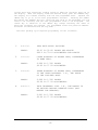
SERVO PRODUCTS PROGRAMMABLE MICRO DRILLER
MODEL 708
OPERATING MANUAL
INFORMATION CONTAINED HEREIN IS PROPREITARY INFORMATION OF SERVO PRODUCTS
COMPANY, 34940 LAKELAND BLVD., EASTLAKE, OHIO. ANY USE OR DUPLICATION OF THIS
INFORMATION FOR ANY PURPOSE OTHER THAN THAT FOR WHICH THE INFORMATION IS
PROVIDED IS PROHIBITED BY SERVO PRODUCTS COMPANY, EXCEPT BY EXPRESS
PERMISSION.
FORM 0800-80119 11/12/04
-2-
TABLE OF CONTENTS
PAGE
5
MODE SWITCH
POWER UP SEQUENCE
5
MANUAL JOG AND HOME KEY
5
BASIC PROGRAMMING
5
ADVANCED PROGRAMMING
9
REAM CYCLE
11
INTERRUPTING CYCLES IN PROGRESS
12
ERROR CONDITIONS
13
NOTE ON METRIC VERSION
13
MICRO-STEPPING
14
MAINTENANCE
14
-3-
-4-
MODE SWITCH
On the front panel is a four position rotary switch called
the
mode
switch. The program mode, “PROG”, is used to enter all variable parameters
and to manually jog the quill up and down. The single position, “SINGLE”, is
used to test the programmed variables. In the “SINGLE” mode, the machine will
execute one peck each time the “ENTER” key is pressed. After each peck, the
quill will retract at the maximum feed rate to the top of the part plus any
clearance programmed.
In the “AUTO” mode the machine will execute as many
pecks as required to drill to the desired final hole depth. After completion
of the drilling operation the quill is left fully retracted. In the “REAM”
mode the machine executes one complete plunge and retracts to the top of the
part at the programmed feed rate. More complete description of the operation
of the machine in its various modes follows.
POWER UP SEQUENCE
On application of power to the micro drilling controller, the stepping
motor will attempt to drive the quill up slightly more than 1.5 inches (or
37.5 mm) to find the top of the quill stroke.
This position is defined as
zero or home.
To minimize mechanical wear, the quill should be fully
extended downward before applying power.
MANUAL JOG AND HOME KEY
With the mode switch in the “PROG” position, it is possible to move the
quill up and down with the “JOG” keys (indicated by arrows).
When a “JOG”
key is depressed, the quill will move in the direction indicated by the arrow
on the “JOG” key. If the key is pressed once and released immediately, the
quill will move only one step (.001” or .025 mm). If the key is not released
after approximately one second, the quill will move in the same direction at
about seven inches per minute (180 mm per min). The quill will not jog above
home zero or below one and one-half inches (37.5 mm) below home zero.
Pressing the “HOME” key will cause the quill to retract to the home zero
position at thirty inches per minute (750 mm per min). It is useful to set
the depth gauge to zero at the home zero position.
BASIC PROGRAMMING
After power has been applied and zero defined, it is necessary to program
the machine for the desired operation.
With the mode switch in the “PROG”
position, the display will alternate from an alpha-numeric mnemonic to the
currently programmed value for the variable.
Upon initialization, all
variables are set equal to zero.
To enter the desired value, simply press
the numeric keys, most significant first. After the first key is pressed the
display will stop flashing. The digit depressed will show in the right-hand
side of the display.
When the next key is depressed, the first digit will
move over one place to the left, and the new digit will be displayed in the
right hand position.
Note: The decimal point is fixed in the display, so
trailing zeroes must be entered until the display reads the desired value.
If a mistake is made while entering data, simply start over, entering the
-5-
correct data with sufficient leading zeroes to bump the incorrect data out of
the display. When the display reads the desired value, push the “ENTER” key.
The display will resume flashing with the new programmed value. Depress the
“NEXT” key to go on to the next programmable variable. Pressing the “NEXT”
key before the “ENTER” key will cause the new value to be discarded, the old
value to be retained, and the next programmable value to be displayed. The
“LAST” key is identical to the “NEXT” key, except reversing the order in
which the variables are scanned. All programmed values are positive numbers.
Distances are measured from the top down.
The basic pecking cycle requires programming of four variables:
1.
2.
3.
4.
F.F.F.F.
FEED RATE WHILE DRILLING.
RANGE:
00.01 TO 30.00 INCHES PER MINUTE
000.2 TO 750.0 MILLIMETERS PER MINUTE
U.U.U.U.
UPPER BOUNDARY OF PECKED HOLE, REFERENCED
TO HOME ZERO.
RANGE:
0.000 TO 1.500 INCHES
00.02 TO 37.50 MILLIMETER
L.L.L.L.
LOWER BOUNDARY OF PECKED HOLE, REFERENCED
TO THE UPPER BOUNDARY. I.E., THE DEPTH
OF THE FINISHED HOLE.
RANGE:
0.000 TO 1.500 INCHES
00.00 TO 37.50 MILLIMETERS
P.P.P.1.
PECK INCREMENT SIZE. I.E., THE AMOUNT TO
BE DRILLED BEFORE CLEARING CHIPS (NOT
NEEDED FOR REAMING).
RANGE:
0.001 TO 1.500 INCHES
00.00 TO 37.50 MILLIMETERS
-6-
EXAMPLE 1. (Metric units in parenthesis)
Suppose it is desired to drill a hole 0.250 (6.25 mm) inches deep in a
block 1.000 (25 mm) tall.
The material is such that it can be drilled at
01.00 inch per minute (25 mm per min) and chips must be cleared after every
0.050 inches (1.25) mm of drilling.
The following procedure should be
followed:
1.
With power off, pull down quill until fully extended.
2.
Plug in A.C. power cord (if not plugged in) and turn on power.
3.
Put mode switch to “PROG” setting.
4.
At this point the display should be flashing “F.F.F.F.”
alternating with “00.00”. Enter the desired feed rate as follows:
“1”, “0”, “0”, “ENTER”. (“2”, “5”, “0”, “ENTER”)
Now, the display should be flashing “F.F.F.F.” and “01.00”, (“025.0”).
5.
Press “NEXT”. The display will flash “U.U.U.U” and “0.000”.
Position the head so that the drill point is 1.500 inches (37.5 mm) from
the base. This places the home zero 0.500 inches (12.5 mm) above the part.
So, program the upper boundary to be 0.500 (12.5 mm).
“5”, “0”, “0”, “ENTER”. (“1”, “2”, “5”, “0”, “ENTER”)
Now, the display should be flashing “U.U.U.U.” and “0.500”, (“12.50”).
Alternately, the quill could be manually jogged until the tool is just
touching the top of the part, or the desired position is displayed. Then
press “ENTER”. This will cause the displayed current quill position to be
stored as the “U.U.U.U” parameter. That value will then be used as the top
of the part.
6.
Press “Next”.
The display will flash “L.L.L.L.” and “0.000”.
The desired finished hole depth is 0.250 inches (6.25 mm) so enter the
following:
“2”, “5”, “0”, “ENTER”. (“6”, “2”, “5”, “ENTER”)
Now the display should be flashing “L.L.L.L.” and “0.250”, (“06.25”).
7.
Press “NEXT”. The display will flash “P.P.P.1.” and “0.000”. The
desired pecking increment is 0.050 inches (1.25 mm) so enter the following:
“5”, “0”, “ENTER”. (“1”, “2”, “5”, “ENTER”)
Now the display should be flashing “P.P.P.1.” and “0.050”, (“01.25”).
-7-
8.
To review the programmed data, press the “LAST” key. Each time
the “LAST” key is pressed, the display will show the previous programmable
variable. When satisfied that all variables are programmed as desired, go
on to step 9. Otherwise, alter the programmed values as required.
9.
To test the program, turn the mode switch to the “SINGLE”
position.
The machine will immediately drive the quill to the home zero
position.
As the spindle is not under the control of the micro drilling
controller, it should be turned on and its speed adjusted at this time.
Then, press the “ENTER” key. The micro drilling controller will drive the
quill to the upper boundary of the hole to be drilled at 30 inches per
minute.
Press the “ENTER” button again.
The machine will drill .050
inches (1.25 mm) into the part at the programmed feed rate of 1 inch per
minute (25 mm per min) then retract to the upper boundary at 30 inches per
minute (750 mm per min) and wait until the “ENTER” key is pressed or the
mode switch is changed.
Each time the enter key is pressed, the machine
will travel rapidly, 30 inches per minute (750 mm per min) to the last
depth already drilled, then down one more peck increment, .050 inches (1.25
mm), in this case at the programmed feed rate, then rapid back to the upper
surface. If the mode switch is changed to the “AUTO” position, the machine
will complete all remaining pecks without any other keys being pressed. If
the mode switch is moved to the “PROG” position, the machine will complete
the peck in progress, then travel rapidly to home zero and halt execution.
CAUTION:
CHANGING THE MODE SWITCH FROM SINGLE, AUTO OR REAM TO PROG MODE
DURING THE DRILLING OPERATION WILL STOP THE DRILLING CYCLE. USE THE “RESET”
BUTTON TO STOP THE QUILL IN THE EVENT OF A TOOL BREAKAGE OR OTHER EMERGENCY.
-8-
ADVANCED PROGRAMMING
Provision has been made for four additional variables to be programmed.
They are programmed the same way as the first four variables. The mnemonics
and descriptions of variables follow. (These variables aren’t necessary for
all drilling operations, but provide more efficient use of the micro drilling
controller.)
5.
6.
7.
8.
9.
10.
P.P.P.2.
MAXIMUM PECK. IN THE EVENT THAT IT IS DESIRED TO
DRILL LARGER PECKS NEAR THE TOP OF THE HOLE THAN AT
THE BOTTOM, P.P.P.1. REPRESENTS THE MINIMUM PECK
AND P.P.P.2. REPRESENTS THE MAXIMUN PECK. THE
CONTROLLER WILL BEGIN PECKING WITH P.P.P.2. AS THE
FIRST PECK SIZE. THE PECK SIZE WILL DIMINISH WITH
EACH PECK UNTIL THE MINIMUM PECK SIZE IS REACHED.
THE REMAINDER OF THE HOLE WILL BE DRILLED WITH THE
PECK SIZE EQUAL TO P.P.P.1., THE MINIMUM PECK. SOME
RESTRICTIONS APPLY TO THE VALUES WHICH CAN BE
PROGRAMMED FOR P.P.P.1 AND P.P.P.2. SEE ERROR
CONDITIONS.
RANGE:
P.P.P.2. GREATER THAN P.P.P.1. AND (P.P.P.1. +
P.P.P.2.) LESS THAN L.L.L.L.
C.C.C.C.
CLEARANCE AT THE UPPER WORK SURFACE. I.E. THE
DISTANCE ABOVE PART TO WHICH TOOL IS TO BE
WITHDRAWN BETWEEN PECKS.
RANGE:
C.C.C.C. LESS THAN U.U.U.U.
o.o.o.o.
OFFSET AT THE PREVIOUSLY PECKED DEPTH. I.E. THE
DISTANCE ABOVE THE LAST DEPTH DRILLED TO WHICH THE
TOOL SHOULD TRAVEL AT THIRTY INCHES PER MINUTE (750
MM PER MIN) BEFORE RESUMING DRILLING AT THE
PROGRAMMED FEED RATE.
RANGE:
O.O.O.O. LESS THAN C.C.C.C.
H.H.H.H.
HOLD TIME BETWEEN PECKS ABOVE PART.
RANGE:
00.00 TO 99.99 SECONDS.
D.D.D.D.
Center drill depth. This is used if a centerdrilling action needs to be done prior to drilling
the hole. This parameter is used with the F.F.F.1.
value below.
RANGE:
0.000 TO 1.500 INCHES
00.00 TO 37.50 MILLIMETERS
F.F.F.1.
Feed rate for center drilling action.
RANGE:
00.01 TO 30.00 INCHES PER MINUTE
000.2 TO 750.0 MILLIMETERS PER MINUTE
-9-
EXAMPLE 2.
Continuing from example one, suppose the amount of material that can be
removed from the part is greater at the top of the hole than at the bottom.
Let the maximum peck size be .050 inches (1.25 mm) and the minimum be .005
inches (.12 mm).
Also that the tool should pause for .5 seconds, .010
inches (.25 mm) above the part to clear chips. Additionally, let the quill
travel rapidly to .003 inches (.07 mm) above the last drilled depth before
resuming drilling at the programmed feed rate. The following steps may be
followed to achieve the desired results.
1. Review the first three programmed variables to make sure they are
programmed as per example one. If not, repeat steps three through six
of example one.
2. Use the “NEXT” or “LAST” key to get P.P.P.1. flashing in the
display. Enter the desired minimum peck as follows:
“0”, “0”, “0”, “5” “ENTER”. (“0”, “0”, “1”, “2”, “ENTER”)
Now, the
(“00.12”).
display
should
be
flashing
“P.P.P.1.”
and
“0.005”,
Note: It is only necessary to insert enough zeroes to bump the old
value from the display.
3. Press “NEXT”. The display will
Enter the maximum peck as follows:
flash
“P.P.P.2.”
and
“0.000”.
“5”, “0”, “ENTER”. (“1”, “2”, “5”, “ENTER”)
Now, the
(“01.25”).
display
should
be
flashing
4. Press “NEXT”. The display will
Enter the desired clearance as follows:
flash
“P.P.P.2.”
and
“C.C.C.C.”
and
“0.050”,
“0.000”.
“1”, “0”, “ENTER”. (“2”, “5”, “ENTER”)
Now, the
(“00.25”).
display
should
be
flashing
5. Press “NEXT”. The display should be
“0.000”. Enter the desired offset as follows:
“C.C.C.C.”
flashing
and
“0.010”,
“o.o.o.o.”
and
“3”, “ENTER”. (“7”, “ENTER”)
Now, the display should flash “o.o.o.o.” and “0.003”, (“00.07”).
6. Press “NEXT”. The display should flash “H.H.H.H.” and “00.00”.
Enter the desired hold time as follows:
“5”, “0”, “ENTER”.
Now, the display should flash “H.H.H.H.” and “00.50”.
- 10 -
7. Review the programmed variables as per example one, step eight.
Any or all of the variables may be changed. Sufficient leading zeroes
must be provided to bump the old value out of the display. If a wrong
value is entered, simply continue entering the correct value with
enough leading zeroes.
Pressing the “ENTER” key causes the value in
the display to be stored. Pressing the “NEXT” or “LAST” key before the
“ENTER” key causes the newly entered data to be discarded and the
previously stored data to be retained.
8. Test the program as per example one, step nine. In the “SINGLE”
mode, after the “ENTER” key is pressed the first time, the machine will
travel rapidly to ten thousandths, (.25 mm), above the upper work
surface of the part. Pressing the “ENTER” key again causes the quill
to lower at the controlled rate to the maximum peck size, P.P.P.2.,
fifty thousandths, (1.25 mm), below the upper surface.
It then
automatically retracts to ten thousandths, (.25 mm), above the upper
surface at thirty inches per minute, (750 mm per min). Press “ENTER”
again.
The quill rapids down to forty-seven thousandths, (1.17 mm),
below the upper surface, three thousandths, (.07 mm), above where it
last left off. It then goes down further at the programmed feed rate,
making a smaller peck than the first one, and rapiding up to above the
surface.
It will continue in this fashion, one peck at a time in
“SINGLE” mode, or may be put into “AUTO” mode to complete the hole.
REAM CYCLE
With the mode switch in the “REAM” position, after pressing the “ENTER”
key, the machine will travel rapidly to the specified clearance above the
work surface, then continue at the programmed feed rate until the desired
hole depth is reached. It will then retract at the programmed feed rate to
the specified clearance above the upper surface, and then retract further
to home zero at thirty inches per minute (750 mm per min). Variables are
programmed the same as for a peck cycle, with the exception of P.P.P.1.,
which may be omitted.
- 11 -
INTERRUPTING CYCLES IN PROGRESS
There are two ways to stop
techniques are detailed below.
1.
a
cycle
from
being
completed.
These
POWER SWITCH
The power switch located on the back of the controller may be
switched to the off position. This causes the machine to stop where
it is.
When switched on again the machine will go through its
entire initialization procedure. The quill will seek home zero and
all programmed variables will be cleared to zero.
This method
should be used only in emergencies or when the program must be
changed anyway.
2.
RESET
The reset button is a momentary contact push button located on
the front panel. Pressing the reset button will cause the machine
to halt at its current position. At this time the operator has two
options. He may press the “ENTER” key to resume operation as if no
reset had occurred, or he may change the mode switch to any other
position. If the mode switch is changed to the “PROG” position, the
machine will retract immediately to the home zero position. If the
mode switch is moved to any position other than “PROG”, a new
operation should not be started until the “HOME” key is depressed.
When the “HOME” key is pressed, the quill will retract to home zero,
and the machine initialized to start a new cycle.
To begin a
complete new cycle press “ENTER”.
The reset button is to be used
most often for interrupting cycles, as none of the programmed
variables are changed and the operator has the option of resuming
the cycle without starting over.
If the setup is changed, the
operator must make sure all programmed variables are still correct.
(I.E., If a broken tool is replaced, the upper work surface should
be reprogrammed.)
- 12 -
ERROR CONDITIONS
If an error should occur during programming, the machine will display
E.E.E.E. when the mode switch is changed from the “PROG” position.
(Exception: If the feed rate is programmed to zero, the error will not be
indicated until after the “ENTER” key is depressed.)
The nature of the
error may be determined by returning the mode switch to the “PROG”
position.
At this time the display will be flashing one of the
programmable variables.
The nature of the error will determine which of
the programmable variables will be displayed. From comparing the displayed
variable to the following list, one may determine the required programming
change.
VARIABLE
DISPLAYED
F.F.F.F.
ERROR CONDITION
Feed rate out of bound.
U.U.U.U.
Upper work surface plus hole depth greater
than machine stroke.
L.L.L.L
Maximum plus minimum peck size greater
than hole depth.
P.P.P.1.
Peck size equal to zero.
C.C.C.C.
Clearance greater than upper work surface.
o.o.o.o.
Offset greater than upper work surface.
NOTE ON METRIC VERSION
The metric version of the micro drilling controller moves in machine
increments of 0.25 millimeters. Due to the limitations of the four digit
display, the least significant digit of the programmable variables
representing distance has been omitted. To see this, jog down one step at
a time in the “PROG” mode.
With the display flashing U.U.U.U. press the
“ENTER” key after each step. Notice how the least significant digit counts
0,2,5,7,0. The machine is actually moving .025 millimeters per step, and
truncating the .005 for display purposes.
Similarly, when entering data,
any value may be entered for the least significant digit, but the actual
value used by the machine will be displayed after the “ENTER” key is
pressed (truncated as per previous description).
- 13 -
MICRO-STEPPING
Micro-stepping with the programmable microdriller can be invoked
automatically by programming a federate of 3.00 ipm or less in “F.F.F.F.”.
In this mode, all of the three available drilling cycles operate in the
same way as in normal stepping except for the quill travel speed discussed
in more detail further below. Use micro stepping primarily when drilling
small diameter holes in hard to drill materials. Micro-stepping as opposed
to regular stepping is a drive technique applied to the motor that is used
to move the quill up and down. It will make the motor move the quill very
smoothly to keep uniform pressure on the drill. Small drills are generally
fragile and break very often as a result of excessive pressure. Use microstepping to get clean holes and longer tool life. When a federate of 3 ipm
or less is used, the microdriller will operate in exactly the same way as
in regular stepping described earlier. All drilling cycles will go through
the same sequences. The only difference is in the speed at which the quill
travels throughout the cycle. Entering a 3 ipm or less federate puts the
machine in micro-stepping such that in all cases the following procedure
will be used.
1.
- All cutting will be done in micro-stepping mode at the
programmed “F.F.F.F.” feedrate.
2.
- All movements of the tool while inside the material that
is being cut whether going up or down will also be done in microstepped mode at the “F.F.F.F.” feedrate.
3.
– The quill will still travel to the top of the working
surface or retract back to home zero position at 30.00 ipm.
MAINTENANCE
The only user serviceable part of the micro drilling controller is the
fuse located on the back panel of the controller. An indication of a blown
fuse is blank display and no motor activity on power up. Replacement fuse
must be on-half ampere, 250 volt AGC type. For other repairs, contact the
factory.
For drill press maintenance,
Maintenance Instructions manual.
consult
Drill
Press
Operating
SERVO PRODUCTS COMPANY
Web: www.servoproductsco.com
CALIFORNIA BRANCH
HEADQUARTERS
FLORIDA BRANCH
1355 W. Foothill Blvd.
Azusa, CA 91702
Ph. 626.691.0121 Fax 626.334.7301
34940 Lakeland Blvd.
Eastlake, OH 44095
Ph. 440.942.9999 Fax 440.942-9100
8950 131 Ave. N.
Largo, FL 33773
Ph. 727.585.8555 Fax 727.585.6555
- 14 -
st
and