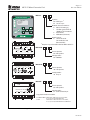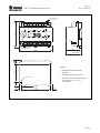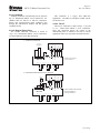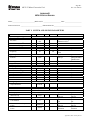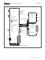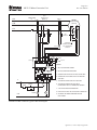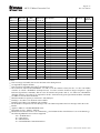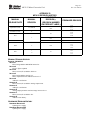
1
3714 Kinnear Place Saskatoon, SK Canada S7P 0A6 Ph: (306) 373-5505 Fx: (306) 374-2245 www.littelfuse.com/relayscontrols MPU-32 MANUAL MOTOR PROTECTION UNIT Revision 5-A-090514 LITTELFUSE STARTCO TRIP MOTOR PROTECTION UNIT ALARM RUN MPU-32 MAIN MENU Metering Ñ ²Messages Ñ Setup Ñ UPI ESC ENTER RESET Copyright 2014 by Littelfuse Startco All rights reserved. Document Number: PM-1115-EN Printed in Canada. Factory default password is 1111 New Password See Section 4.5 Motor Identification Page i Rev. 5-A-090514 MPU-32 Motor Protection Unit TABLE OF CONTENTS SECTION PAGE List of Figures ........................................................................ ii List of Tables ......................................................................... ii 1 Introduction ..........................................................1-1 1.1 General.....................................................................1-1 1.2 MPU-32 Features ....................................................1-1 1.2.1 Protection .....................................................1-1 1.2.2 Metering.......................................................1-1 1.2.3 Data Logging ...............................................1-1 1.2.4 Inputs and Outputs ......................................1-1 1.2.5 Operator Interface .......................................1-1 1.2.6 MPS-RTD Module (Optional)....................1-1 1.2.7 MPS-DIF Differential Module (Optional) .1-1 1.2.8 Communications .........................................1-1 1.3 Ordering Information ..............................................1-1 2 Installation..............................................................2-1 2.1 General.....................................................................2-1 2.2 MPU-32 Motor Protection Unit..............................2-1 2.3 MPU-CIM Current Input Module ..........................2-1 2.4 Earth-Fault CT’s ......................................................2-1 2.5 MPS-RTD RTD Module ........................................2-1 2.6 MPS-DIF Differential Module ...............................2-1 2.7 MPU-32/MPU-16A Compatibility.........................2-1 3 System Wiring .......................................................3-1 3.1 General.....................................................................3-1 3.2 Wiring Connections ................................................3-2 3.2.1 MPU-32 Connections .................................3-2 3.2.1.1 Supply Voltage...............................3-2 3.2.1.2 CIM Input .......................................3-2 3.2.1.3 Digital Input ...................................3-2 3.2.1.4 Analog Output................................3-2 3.2.1.5 PTC or RTD Input (Local) ............3-2 3.2.1.6 I/O Module Interface .....................3-2 3.2.1.7 RS/EIA/TIA-232 Communications .........................................3-3 3.2.2 MPU-CIM Connections..............................3-3 3.2.2.1 Standard..........................................3-4 3.2.2.2 Residual Earth-Fault ......................3-4 3.2.2.3 Two-CT ..........................................3-4 3.2.3 MPS-RTD Connections and Address Selection ......................................................3-6 3.2.4 MPS-DIF Connections................................3-6 3.2.4.1 Core Balance ..................................3-6 3.2.4.2 MPU Summation ...........................3-6 3.2.4.3 DIF Summation..............................3-6 3.2.5 Cable Restraint........................................ 3-6 3.2.6 Dielectric-Strength Testing .........................3-6 4 Operation and Setup .............................................4-1 4.1 Display and Indication ............................................4-1 4.1.1 Front-Panel LED Indication .......................4-1 4.1.2 Rear-Panel LED Indication.........................4-2 4.1.3 Display Contrast and Test ...........................4-2 SECTION PAGE 4.2 Setup ........................................................................ 4-2 4.2.1 Phase-CT Inputs .......................................... 4-2 4.2.2 Earth-Fault-CT Input .................................. 4-2 4.2.3 Motor Data .................................................. 4-2 4.2.4 Output Relay Assignment .......................... 4-2 4.2.5 Digital Input ................................................ 4-3 4.2.6 Analog Output............................................. 4-3 4.2.7 Miscellaneous Configuration ..................... 4-4 4.2.8 Communications ......................................... 4-4 4.3 Metering .................................................................. 4-4 4.4 Messages ................................................................. 4-5 4.4.1 Trip Reset .................................................... 4-5 4.4.2 Data Logging............................................... 4-5 4.4.3 Statistical Data ............................................ 4-6 4.4.4 Emergency Thermal Reset ......................... 4-6 4.5 Password Entry and Programming......................... 4-6 4.6 MPS-RTD ............................................................... 4-6 4.7 MPS-DIF ................................................................. 4-7 5 Protective Functions ........................................ 5-1 5.1 General............................................................... 5-1 5.2 Overload ............................................................ 5-1 5.2.1 Thermal Model ....................................... 5-1 5.2.2 Locked-Rotor Times ............................... 5-4 5.2.3 Emergency Thermal Reset...................... 5-4 5.3 Overcurrent ........................................................ 5-4 5.4 Auxiliary Overcurrent ........................................ 5-5 5.5 Reduced Overcurrent ......................................... 5-5 5.6 Jam ..................................................................... 5-5 5.7 Earth Fault ......................................................... 5-5 5.8 Current Unbalance ............................................. 5-6 5.9 Phase Loss ......................................................... 5-6 5.10 Phase Reverse .................................................... 5-6 5.11 Undercurrent ...................................................... 5-6 5.12 Differential Current Protection .......................... 5-6 5.13 Starts per Hour/Time Between Starts ................ 5-7 5.14 PTC Temperature (Local) .................................. 5-7 5.15 RTD Temperature (Local) ................................. 5-7 5.16 RTD Temperature (MPS-RTD Module) ............ 5-8 5.17 Hot-Motor Compensation .................................. 5-8 6 Theory of Operation ........................................ 6-1 6.1 Signal-Processing Algorithms ........................... 6-1 6.2 RTD Module (MPS-RTD) ................................. 6-1 6.3 Differential Module (MPS-DIF) ........................ 6-1 7 Communications .............................................. 7-1 7.1 Personal-Computer Interface ............................. 7-1 7.1.1 Firmware Upgrade .................................. 7-1 7.1.2 SE-Comm-RIS ........................................ 7-1 7.2 Network Interface .............................................. 7-1 7.2.1 TIA-485 Option ...................................... 7-1 7.2.2 DeviceNet Option ................................... 7-1 7.2.3 Ethernet Option ...................................... 7-1 Table of Contents Page ii Rev. 5-A-090514 MPU-32 Motor Protection Unit SECTION PAGE 8 Technical Specifications................................... 8-1 MPU-32.............................................................. 8-1 Current Input Module (MPU-CIM).................... 8-3 RTD Module (MPS-RTD) ................................. 8-3 Differential Module (MPS-DIF) ........................ 8-4 9 Warranty .......................................................... 8-4 Appendix A MPU-32 Menu Map ................................ A-1 Appendix B MPU-32 Setup Record ............................ B-1 Appendix C 1-A Direct-Input Configuration .............. C-1 Appendix D MPU-32 TIA-232 Modbus Protocol ....... D-1 Appendix E Communications Database Table ............ E-1 Appendix F Register Formats....................................... F-1 Appendix G MPU-32 Revision History ...................... G-1 8.1 8.2 8.3 8.4 LIST OF FIGURES FIGURE 1.1 1.2 2.1 2.2 2.3 2.4 2.5 2.6 2.7 2.8 3.1 3.2 3.3 3.4 3.5 3.6 3.7 3.8 3.9 3.10 3.11 4.1 4.2 5.1 5.2 5.3 PAGE LIST OF TABLES TABLE 3.1 3.2 4.1 4.2 4.3 4.4 4.5 5.1 PAGE CA-945 Adapter Pinout ......................................... 3-3 MPS-RTD Address Selection ................................ 3-6 UPI LED Functions ................................................ 4-1 Output-Relay Functions ......................................... 4-3 Digital-Input Functions .......................................... 4-3 Analog-Output Parameters..................................... 4-4 Metering Display .................................................... 4-5 Fault Duration Required for Trip or Alarm........... 5-4 DISCLAIMER Specifications are subject to change without notice. Littelfuse Startco is not liable for contingent or consequential damages, or for expenses sustained as a result of incorrect application, incorrect adjustment, or a malfunction. Motor Protection Unit Block Diagram ...................1-2 MPU-32 Ordering Information...............................1-3 MPU-32 Outline and Panel-Mounting Details .........2-2 MPU-32 Outline and Surface-Mounting Details......2-3 MPU-CIM Outline and Mounting Details .............2-4 EFCT-1 Outline and Mounting Details ..................2-5 EFCT-2 Outline and Mounting Details ..................2-6 EFCT-26 Outline and Mounting Details ................2-7 MPS-RTD Outline and Mounting Details .............2-8 MPS-DIF Outline and Mounting Details ...............2-9 Typical MPU-32 Connection Diagram ..................3-1 Analog-Output Connections ...................................3-2 Local Temperature-Sensor Connections ................3-2 I/O Module Connection Diagram ...........................3-2 MPU-CIM Schematic .............................................3-3 MPU-CIM Standard Connections ..........................3-4 Other MPU-CIM Connections ...............................3-5 MPS-RTD Connection Diagram ............................3-7 Core-Balance Connection .......................................3-7 MPU-Summation Connection ................................3-8 DIF-Summation Connection...................................3-8 Menu Example ........................................................4-1 Menu Symbols.........................................................4-1 Class-20 Overload Curve ........................................5-3 Asymmetrical-Current Multipliers .........................5-5 Used I2t Bias Curve .................................................5-8 Table of Contents Page 1-1 Rev. 5-A-090514 MPU-32 Motor Protection Unit 1. INTRODUCTION 1.1 GENERAL The MPU-32 is a motor-protection relay that provides integrated protection, metering, and data-logging functions for fixed- and variable-frequency applications. The MPU-32 can be programmed using the front-panel operator interface, the TIA-232 port, or an optional communications network. The MPU-32 configuration described in this manual uses a current-input module (CIM) and is shown in Fig. 1.1. The MPU-32 is also available in a 1-A-directinput configuration and Appendix C contains information specific to this configuration. 1.2 MPU-32 FEATURES 1.2.1 PROTECTION Overload (49, 51) Overcurrent (50, 51) Earth fault (50G/N, 51G/N) Unbalance (46) Phase loss (46) Phase reverse (46) Jam Undercurrent (37) Starts per hour (66) Differential (87) PTC overtemperature (49) RTD temperature (38, 49) 1.2.2 METERING Line currents Current unbalance Positive-sequence current (I1) Negative-sequence current (I2) Zero-sequence current (3I0, calculated) Earth-leakage current (CT input) Differential currents Used thermal capacity Thermal trend RTD temperatures Frequency 1.2.3 DATA LOGGING One-hundred records Date and time of event Event type Cause of trip Line currents Current unbalance Earth-leakage current Differential currents Used thermal capacity Thermal capacity used during starts Start time RTD temperatures Trip counters Running hours 1.2.4 INPUTS AND OUTPUTS Phase-current inputs Earth-leakage-current input Programmable digital input (24 Vdc) 24-Vdc source for digital input 4–20-mA analog output, programmable Temperature-sensor input, Pt100 RTD or PTC I/O module interface Three output relays, programmable TIA-232 communications Network communications 1.2.5 OPERATOR INTERFACE 4 x 20 backlit LCD display Display-control and programming keys LED status indication 1.2.6 MPS-RTD MODULE (OPTIONAL) Eight inputs per module Individually selectable RTD types RTD Voting Solid-state multiplexing Up to three modules per system Remote operation up to 1.2 km (4,000’) Powered by MPU-32 1.2.7 MPS-DIF DIFFERENTIAL MODULE (OPTIONAL) 3-CT core balance connection 6-CT summation connection Remote operation up to 1.2 km (4,000’) Powered by MPU-32 1.2.8 COMMUNICATIONS The standard communications interface is a TIA-232 port using the Modbus RTU protocol. In addition to the standard interface, network communications options include TIA-485 with both Modbus RTU and A-B DF1 protocols , DeviceNetTM, and an IEEE 802.3 port with Modbus TCP Ethernet protocol. 1.3 ORDERING INFORMATION See Fig. 1.2 for MPU-32, MPU-CIM, MPS-RTD and MPS-DIF model numbers. Introduction Page 1-2 Rev. 5-A-090514 MPU-32 Motor Protection Unit A 13 B 14 C 15 COM 16 29 EF 22 21 20 NC MPU-32 SUPPLY L1 2 L2 3 8 PTC/RTD INPUT TA TB TC 17 18 19 ON REAR PANEL 13 14 15 16 4-20mA ANALOG OUTPUT AB AA 15 14 +24V KEYPAD: + 25 26 DIFFERENTIAL MODULE PWR COMM 4 x 20 ALPHANUMERIC LCD, LED BACKLIGHTING 24 V DC DIGITAL INPUT 0V 27 28 29 + 30 +24V 31 11 + 12 0V 10 + I/O COMMUNICATIONS +24V 15 MPS-RTD 16 17 RTD MODULE 18 LED INDICATORS: DTR SG OPTIONAL NETWORK COM RD DCE 2 SHIELD 4 TIA-232 5 RTD 2 6 RTS 11 12 OUTPUT RELAY 2 10 1 9 OUTPUT RELAY 3 4 6 7 OUTPUT RELAY 1 C D R C D R RTD 3 TD CTS C D R RTD 4 3 SHIELD 7 8 7 6 5 1 PHASE CT 4 3 2 1 1 9 8 7 1 5 C DIFFERENTIAL CT 6 5 4 1 5 C DIFFERENTIAL CT 3 2 1 1 5 C DIFFERENTIAL CT 21 22 23 24 25 26 27 28 29 30 31 32 33 34 R D C RTD 5 5 S R 5 PHASE CT S R 13 - 0V 1 DCD PHASE CT LED INDICATORS: DISPLAY: UP DOWN LEFT RIGHT RESET ESC ENTER 12 1 11 5 10 S 9 R MPS-DIF SPG ANALOG OUTPUT SELF/LOOP POWER SELECTOR L S CURRENT INPUT MODULE 17 18 EF1 19 Y 20 CONFIGURATION X 21 SELECTION 22 E 23 S 24 5 25 EARTH FAULT CT R 26 1 27 LED INDICATORS: TRIP ALARM RUN UPI (USER PROG INDICATOR) NS (NETWORK STATUS) 23 MS (MODULE STATUS) 24 ER (MPU-32 ERROR) MPU-CIM RTD 1 8 C D R PWR 14 COMM 13 12 11 10 9 8 7 6 5 ADDRESS SWITCHES 4 3 20 2 1 19 SHIELD R D C R D C RTD 6 RTD 7 SHIELD R D C RTD 8 SPG 5 OUTPUT RELAY CONTACTS SHOWN WITH MPU-32 DE-ENERGIZED. FIGURE 1.1 Motor Protection Unit Block Diagram. Introduction Page 1-3 Rev. 5-A-090514 MPU-32 Motor Protection Unit MPU-32LITTELFUSE STARTCO MOTOR PROTECTION UNIT TRIP - MPU-32 Options: 00 CIM Input (1) 01 1-A CT Input MAIN MENU Metering Ñ ²Messages Ñ Setup Ñ ALARM RUN UPI Network Communications: 0 None, TIA-232 only 1 TIA-485 c/w A-B®DF1 & Modbus®RTU Protocols 2 DeviceNet™ 4 IEEE 802.3 (Ethernet) ESC ENTER RESET Power Supply: 0 Universal ac/dc (65 to 265 Vac and 80 to 275 Vdc) (1) Requires input from MPU-CIM or MPU-16A ICT-x 27 26 25 24 23 22 21 20 19 18 17 16 15 14 13 1 R 5 S E X Y E E C C B A F F O EARTH FAULT 1 2 M C U R R E NT I N P UT M O D U L E R 1 PHASE A S 2 5 3 1 4 R 5 MPU-CIM- MPU MPU-CIM PHASE B S 6 5 7 1 8 R 9 PHASE C S 10 5 11 Future Options: 00 No Options 1 12 Configuration: 00 50/60 Hz MPS-RTD- - 34 33 32 31 30 29 28 27 26 25 24 23 22 21 20 19 C D R S C D R C D R S C D R S H P H INP 8 INP 7 INP 6 INP 5 G INPUT MODULE PWR CTU/ MPU COMM INP 1 R 1 D 2 C 3 S H 4 INP 4 COMM 2 4 S 0 V D C H R D C V 9 10 11 12 13 14 15 16 17 18 INP 2 R 5 D 6 Future Options: 00 No Options MPS-RTD INP 3 C 7 R 8 Configuration: 01 8 Input MPS-DIFPWR Future Options: 00 No Options 15 14 S P G DIFFERENTIAL MODULE MPS-DIF CTU/ MPU PHASE A C 1 5 2 - COMM 1 3 PHASE B C 4 5 5 PHASE C 1 6 C 7 5 8 1 9 + COMM 2 4 0 V - + V 10 11 12 13 Configuration: 01 5/1A Isolated Input Supplied Interconnect Cable: S75-M16A-20030. . MPU-CIM to MPU-32 Interconnect Cable, 6 m (19’) Included with MPU-CIM 3124A . . . . . . . . . . I/O Module to MPU-32 Interconnect Cable, 4 m (13’) Included with MPS-RTD and MPS-DIF FIGURE 1.2 MPU-32 Ordering Information. Introduction MPU-32 Motor Protection Unit Page 1-4 Rev. 5-A-090514 Current Transformers: EFCT-1 ......................... Earth-Fault CT, 5-A-primary rating, 82 mm (3.2”) window EFCT-1FC .................... Flux Conditioner for EFCT-1, 70 mm (2.7”) window EFCT-2 ......................... Earth-Fault CT with Flux Conditioner, 5-A primary, 139 mm (5.5”) window EFCT-26 ....................... Earth-Fault CT, 5-A-primary rating, 26 mm (1”) window Other Earth-Fault CT’s .. Contact factory Phase CT’s .................... Contact factory Accessories: MPU-32-SMK .............. Surface-mounting hardware kit MPU-16A-Y92A-96N .. Watertight faceplate cover CA-945 ......................... DB9 to RJ-45 Adapter with 1.5 m (5’) cable SE-ICUSB232 .............. USB to TIA-232 serial converter Software: SE-Comm-RIS .............. PC Interface(1) SE-Flash ....................... Firmware Upgrade(1) (1) Available at www.littelfuse.com/relayscontrols. Introduction MPU-32 Motor Protection Unit 2. INSTALLATION 2.1 GENERAL A basic system consists of an MPU-32, an MPU-CIM, and three 1-A- or 5-A-secondary line-current transformers. See Appendix C for the 1-A-direct-input configuration. Earth-fault protection can be provided from a core-balance CT or from phase CT’s. A core-balance CT (1-A, 5-A, or EFCT series) is recommended. In addition to a single PTC/RTD input provided on the MPU-32, up to three eight-input MPS-RTD modules and one MPS-DIF differential module can be connected to an MPU-32. The MPU-32 switch-mode power supply is rated 65 to 265 Vac and 80 to 275 Vdc. All modules can be mounted in any orientation. 2.2 MPU-32 MOTOR PROTECTION UNIT Outline and details for MPU-32 panel-mounting are shown in Fig. 2.1. The MPU-32 mounts in a 92 mm (3.62”) ¼ DIN square cutout and is secured by a panel-mount clamp. Insert the MPU-32 through the panel cutout and slip the panel-mount clamp over the MPU-32 body. Slide the clamp forward until the latch tabs snap into the mating holes. Lock the unit in place by tightening the four clamp screws against the panel. CAUTION: Do not over tighten the clamp screws as this may deform the clamp and release the latch tabs. Outline and details for MPU-32 surface-mounting are shown in Fig. 2.2. Ensure that the L/S switch is set before installing surface-mounting brackets. See Section 3.2.1.4 for switch positions. A detailed installation instruction sheet is included with the MPU-32-SMK, SurfaceMounting Hardware Kit. 2.3 MPU-CIM CURRENT INPUT MODULE The MPU-CIM can be surface or DIN-rail mounted. Outline and mounting details are shown in Fig. 2.3. To minimize CT-lead burden, an MPU-CIM can be located close to the CT’s. The MPU-CIM terminates phase- and earth-fault-CT secondariesshorting blocks are not required for MPU-CIM outputs. 2.4 EARTH-FAULT CT’S Outline and mounting details for the EFCT-1, EFCT-2, and EFCT-26 are shown in Figs. 2.4, 2.5, and 2.6. 2.5 MPS-RTD RTD MODULE Outline and mounting details for the MPS-RTD are shown in Fig. 2.7. The MPS-RTD will fit inside most motor RTD-termination junction boxes and it is certified for use in Class I, Zone 2 and Class 1, Division 2 Page 2-1 Rev. 5-A-090514 hazardous locations. The MPS-RTD can be surface or DIN-rail mounted. 2.6 MPS-DIF DIFFERENTIAL MODULE Outline and mounting details for the MPS-DIF are shown in Fig 2.8. The MPS-DIF can be surface or DIN-rail mounted. 2.7 MPU-32/MPU-16A COMPATIBILITY The MPU-32 is hardware compatible with existing MPU-16A installations. MPU-16A plug-in terminal blocks mate with the MPU-32 and an MPU-32 can directly replace an MPU-16A with minimal or no wiring changes. I/O connections to MPU-32 terminals 13 to 24, with the exception of terminal 20 which is not connected, are identical to those on the MPU-16A. This allows the MPU-16A upper terminal block to be plugged directly into an MPU-32. If a switch was connected to the MPU-16A program-enable terminal, the switch will not function with the MPU-32. This is usually not a problem since the MPU-32 set points are password protected. If a hard-wired program enable is required, it can be implemented using digital-input terminals 25 and 26 as outlined in Section 4.2.5. If the MPU-16A analog output was used, ensure that the MPU-32 analog output switch is set to the ‘S’ (Self Powered) position. Although MPU-32 terminals 1 to 12 have been rearranged to provide a third relay output (terminals 1, 4, and 9), the MPU-16A lower terminal block can be safely plugged into the equivalent MPU-32 terminal locations. CAUTION: The keying plug installed in position 9 of the MPU-16A lower terminal block must be removed before the terminal block can be plugged into an MPU-32. Use a dental pick, awl, or similar pointed tool to remove the keying plug. If the keying plug is difficult to remove, use the terminal blocks supplied with the MPU-32. A TERMINAL BLOCK WITH A KEYING PLUG WILL DAMAGE THE MPU-32. If the MPU-32 does not power up, ensure that L1 is connected to terminal 2 (not terminal 1) and L2/N is connected to terminal 3 (not terminal 4). If the duplicate L1 and L2 terminals on the MPU-16A are used to power another device, disconnect the outgoing L1 and L2 leads and power the next device directly from the power source. This change is in compliance with current codes that do not permit daisy chaining power connections at plug-in terminals. MPU-32 default relay assignment is the same as the MPU-16A trip- and alarm-relay configuration. For additional information see www.littelfuse.com/ relayscontrols and refer to Technical Note MP-18 Replacing an MPU-16A with an MPU-32. Installation Page 2-2 Rev. 5-A-090514 MPU-32 Motor Protection Unit 132.0 (5.20) 91.1 (3.59) LATCH TAB CLAMP SCREWS PANEL-MOUNT CLAMP PANEL THICKNESS 1.6 (0.06) TO 4.8 (0.19) SIDE TOP 96.0 (3.78) LITTELFUSE STARTCO TRIP MOTOR PROTECTION UNIT 96.0 (3.78) ALARM RUN MPU-32 1 3 1 4 1 5 1 6 1 7 18 19 2 0 2 1 22 23 24 E A A A B C C T T T F B A L S O A B C M TE M P A N OU T CIM MAIN MENU MAIN MENU Metering — Ñ Metering ≤Messages — ²Messages Ñ Setup — Setup Ñ E M N R S S UPI ESC ENTER RESET 6-32 CABLING RESTRAINT FASTENING POINT 4 PLACES FRONT 3 1 30 2 9 28 2 7 2 6 2 5 S 0 2 H V 4 C OMM D IG I N V I /O MOD U LE TIA-232 ONLY RE LA Y 3 RELAY 2 RELAY 1 L 2 L / N 1 12 11 10 9 8 7 6 5 4 3 2 1 REAR 92.0 (3.62) R=4.8 (0.19) MAXIMUM NOTES: 100.0 MINIMUM (3.94) 92.0 (3.62) 1. DIMENSIONS IN MILLIMETRES (INCHES). 2. REAR VIEW SHOWN WITHOUT NETWORK COMMUNICATIONS. 100.0 MINIMUM (3.94) PANEL CUTOUT DETAIL FIGURE 2.1 MPU-32 Outline and Panel-Mounting Details. Installation Page 2-3 Rev. 5-A-090514 MPU-32 Motor Protection Unit 142.9 (5.63) 91.1 (3.59) 8.0 (0.32) HOLE PLUGS (TOP AND BOTTOM SURFACES) SIDE 96.0 (3.78) (0.65) 16.6 TOP LITTELFUSE STARTCO TRIP MOTOR PROTECTION UNIT ALARM 122.5 (4.82) RUN MPU-32 1 3 1 4 1 5 1 6 1 7 18 19 2 0 2 1 22 23 24 E A A A B C C T T T F B A L S O A B C M TE M P A N OU T CIM MAIN MENU MAIN MENU Metering — Ñ Metering ≤Messages — Ñ ²Messages Setup — E M N R S S Setup Ñ 3 1 30 2 9 28 2 7 2 6 2 5 S 0 2 H V 4 C OMM V D IG I N I /O MOD U LE UPI ESC RE LA Y 3 RELAY 2 L RELAY 1 2 L / N 1 12 11 10 9 8 7 6 5 4 3 2 1 ENTER RESET TIA-232 ONLY NOTE 3 REAR 76.2 (3.00) 5.0 9.9 (0.39) (0.20) 19.0 (0.75) FRONT 1. DIMENSIONS IN MILLIMETRES (INCHES). 19.0 (0.75) (NOTE 6) 112.0 2. REAR VIEW SHOWN WITHOUT NETWORK COMMUNICATIONS. (4.41) (NOTE 5) NOTES: 3. MOUNT SURFACE MOUNTING BRACKETS WITH 6-32 x 0.375 PAN-HEAD SCREWS AND LOCKWASHERS (INCLUDED WITH SURFACE-MOUNTING KIT). 4. MPU-32 MOUNTING SCREWS: M4 OR 8-32 PAN HEAD. M4 OR 8-32 TAP (NOTE 5) 25.4 (1.00) 5. MINIMUM CLEARANCE TO ADJACENT OBJECTS. 6. MOUNTING-HOLE PATTERN IDENTICAL TO SURFACE-MOUNT MPU-16A. MOUNTING DETAIL FIGURE 2.2 MPU-32 Outline and Surface-Mounting Details. Installation Page 2-4 Rev. 5-A-090514 MPU-32 Motor Protection Unit CABLE-TIE EYELET 4 PLACES 87.0 (3.43) 27 26 25 24 23 22 21 20 19 18 17 16 15 14 13 E C C B A 1 R 5 S E X Y E F O F EARTH FAULT 2 M 1 MPU MPU-CIM C U R R E NT I N P UT M O D U L E R 1 PHASE A S 2 5 3 1 4 R 5 PHASE B S 6 5 7 1 8 R 9 PHASE C S 10 5 11 1 12 112.5 (4.43) 52.5 (2.07) 56.0 (NOTE 3) (2.20) TOP SIDE SHORTING SCREWS A, B, & C (NOTES 4 & 5) NOTES: 1. DIMENSIONS IN MILLIMETRES (INCHES). 2. MOUNTING SCREWS: M4 OR 8-32. (0.50) 3. OVERALL HEIGHT WHEN MOUNTED ON DIN EN50022 35-mm x 7.5-mm TOP-HAT RAIL. 4. SHORTING SCREWS ARE ACCESSIBLE FROM BOTTOM OF MPU-CIM. 60.0 (2.36) 12.5 BOTTOM 5. SHORTING SCREWS: 6-32 x 0.375 NICKEL-PLATED-BRASS BINDING HEAD. DO NOT SUBSTITUTE. 14.5 (0.57) M4 OR 8-32 TAP 6.8 (0.27) 100.0 (3.94) 6.8 (0.27) MOUNTING DETAIL FIGURE 2.3 MPU-CIM Outline and Mounting Details. Installation Page 2-5 Rev. 5-A-090514 MPU-32 Motor Protection Unit NOTES: 1. DIMENSIONS IN MILLIMETRES (INCHES). 2. MOUNTING SCREWS: M4 OR 8-32. 3. PRESS MOUNTING FEET IN PLACE USING INSTALLATION TOOL PROVIDED. 4. RoHS COMPLIANT. 5. EN 60044-1 COMPLIANT. 121.0 (4.76) 121.0 (4.76) 20.5 (0.81) 56.0 (2.21) 46.0 (1.81) 30.0 (1.18) 80.0 (3.15) NOTE 2 M5 SCREWS TOP MOUNTING DETAIL 25.0 (0.98) 30.0 (1.18) EFCT-1 EARTH FA ULT CT 600 V CLASS, INSULATION CLASS A R R LR 53428 5.0 (0.20) Ø RECESSED FOR 8-mm HEX NUT 1.0 (0.04) DEEP 22.0 (0.87) EFCT - 1FC FLUX CONDITIONER (OPTIONAL) .0 82 23) . (3 69 (2.7 .8 5) 126.0 (4.96) US (5.43) 138.0 MAX C 5.5 (0.22) 110.0 (4.33) FRONT 5.5 (0.22) 56.0 (2.21) SIDE FIGURE 2.4 EFCT-1 Outline and Mounting Details. Installation Page 2-6 Rev. 5-A-090514 MPU-32 Motor Protection Unit NOTES: 1. DIMENSIONS IN MILLIMETRES (INCHES). 2. MOUNTING SCREWS: M5 OR 10-32. 3. RoHS COMPLIANT. 4. EN 60044-1 COMPLIANT. 215.0 (8.46) 26.5 (1.04) 52.3 (2.06) P S1 2S2 P1 31.0 (1.22) 64.0 (2.52) 215.0 (8.46) 162.0 (6.38) M5 OR 10-32 TAP M5 SCREWS TOP MOUNTING DETAIL 31.0 (1.22) 25.0 (0.98) EFCT-2 EARTH FAULT CT 600 V CLASS, INSULATION CLASS A R R LR 53428 139.7 (5.50) FLUX CONDITIONER (INCLUDED) BONDING SCREW 215.0 (8.46) US 5.0 (0.20) DIA 60.0 (2.36) 236 MAX (9.29) C 8.5 (0.33) 198.0 (7.80) FRONT 8.5 (0.33) SIDE FIGURE 2.5 EFCT-2 Outline and Mounting Details. Installation Page 2-7 Rev. 5-A-090514 MPU-32 Motor Protection Unit 68.0 (2.68) 68.0 (2.68) 17.0 (0.67) P S1 2 S2 P1 M4 OR 8-32 TAP 42.6 (1.68) 52.5 (2.07) 26.5 (1.04) 34.0 (1.34) M5 SCREWS 110.0 MAX (0.43) TOP MOUNTING DETAIL 26.5 (1.04) 25.0 (0.98) E F C T- 2 6 E A R T H FA U LT C T 600 V CLASS, INSULATION CLASS A R R C LR 53428 US RECESSED FOR 7-mm HEX NUT 3.0 (0.12) DEEP 7.0 (0.87) 34.0 (1.34) 72.0 (2.83) 4.0 (0.16) Ø .0 26 2) 0 (1. 58.0 (2.28) 52.5 (2.07) 5.0 (0.20) 5.0 (0.20) FRONT SIDE NOTES: 1. DIMENSIONS IN MILLIMETRES (INCHES). 2. MOUNTING SCREWS: M4 OR 8-32. MOUNTING FOOT INSTALLATION TOOL 3. PRESS MOUNTING FEET IN PLACE USING INSTALLATION TOOL PROVIDED. (DETAIL ‘A’) 4. RoHS COMPLIANT. DETAIL ‘A’ 5. EN 60044-1 COMPLIANT. 6. NOT ALL CERTIFICATIONS SHOWN. FIGURE 2.6 EFCT-26 Outline and Mounting Details. Installation Page 2-8 Rev. 5-A-090514 MPU-32 Motor Protection Unit CABLE-TIE EYELET 4 LOCATIONS 34 33 32 31 30 29 28 27 26 25 24 23 22 21 20 19 C D R S C D R C D R S C D R S H P H INP 8 INP 7 INP 6 INP 5 G INPUT MODULE 87.0 (3.43) PWR CTU/ MPU COMM INP 1 R 1 D 2 C 3 S H 4 INP 2 R 5 D 6 MPS-RTD 2 4 S 0 V D C H R D C V 9 10 11 12 13 14 15 16 17 18 INP 3 C 7 ADDRESS SWITCH ACCESS COVER R 8 INP 4 COMM 52.5 112.5 (4.43) (2.07) 12.5 (0.50) 56.0 (NOTE 3) (2.20) 1. DIMENSIONS IN MILLIMETRES (INCHES). (2.36) 60.0 NOTES: 2. MOUNTING SCREWS: M4 OR 8-32. 3. OVERALL HEIGHT WHEN MOUNTED ON DIN EN50022 35-mm x 7.5-mm TOP-HAT RAIL. (0.57) 14.5 M4 OR 8-32 TAP 6.3 100.0 6.3 (0.25) (3.94) (0.25) FIGURE 2.7 MPS-RTD Outline and Mounting Details. Installation Page 2-9 Rev. 5-A-090514 MPU-32 Motor Protection Unit CABLE-TIE EYELET 4 PLACES PWR COMM 87.0 (3.43) 15 14 S P G DIFFERENTIAL MODULE MPS-DIF CTU/ MPU PHASE A C 1 5 2 1 3 PHASE B C 4 5 5 PHASE C 1 6 C 7 5 8 1 9 + 2 4 0 V - + V 10 11 12 13 COMM 52.5 (2.07) 56.0 (NOTE 3) (2.20) 112.5 (4.43) TOP SIDE NOTES: 1. DIMENSIONS IN MILLIMETRES (INCHES). 2. MOUNTING SCREWS: M4 OR 8-32. 3. OVERALL HEIGHT WHEN MOUNTED ON DIN EN50022 35-mm x 7.5-mm TOP-HAT RAIL. 12.5 60.0 (2.36) (0.50) BOTTOM 14.5 (0.57) M4 OR 8-32 TAP 6.8 (0.27) 100.0 (3.94) 6.8 (0.27) MOUNTING DETAIL FIGURE 2.8 MPS-DIF Outline and Mounting Details. Installation MPU-32 Motor Protection Unit Page 2-10 Rev. 5-A-090514 This page intentionally left blank. Installation Page 3-1 Rev. 5-A-090514 MPU-32 Motor Protection Unit 3. SYSTEM WIRING 3.1 GENERAL A typical connection diagram for an MPU-32 with an MPU-CIM is shown in Fig. 3.1. See Sections 3.2.3 and 3.2.4 for MPS-RTD and MPS-DIF connections. See Appendix C for the 1-A-direct-input configuration. PHASE CT’S (NOTE 9) CONTACTOR K1 A EARTH-FAULT CT MOTOR (NOTE 6) B +t˚ t˚ C 12 11 10 9 1 5 S R 8 7 6 5 4 3 2 1 5 S R 1 5 S R PHASE C PHASE B 1 Pt100 RTD SENSOR PHASE A MPU-CIM (NOTE 8) A MPU C E O F B C M 2 E F 1 Y EARTH FAULT X E S 5 R ALTERNATE CONNECTION FOR PTC-THERMISTOR SENSOR(S) 1 BROWN GREEN BLUE WHITE RED BLACK 13 14 15 16 17 18 19 20 21 22 23 24 25 26 27 (NOTE 10) (NOTE 6) (NOTE 3) OUTPUT (NOTE 4) 13 14 15 16 17 18 19 20 21 22 23 24 A B C S1 CIM C T T T O A B C M TEMP E F A B A A L S AN OUT TIA-232 ONLY (NOTE 7) 31 30 29 28 27 26 25 + + S - 0 + 24 H V V COMM DIG IN I/O MODULE RELAY 2 12 11 10 9 E M N R S S RELAY 3 7 6 5 L1 L 2 4 N L 1 3 2 1. MPU-32 REAR VIEW SHOWN. 1 MPU-32 RELAY 1 8 8 NOTES: 2. RELAYS SHOWN DE-ENERGIZED. 3. GROUND CABLE SHIELDS AT MPU-32 END ONLY. 1 4. GROUND OUTPUT-CABLE SHIELD AT RECEIVER END ONLY. 5. ALTERNATE CONTACTOR-COIL LOCATION. START STOP (NOTE 5) 6. ALTERNATE CONNECTION FOR PTC-THERMISTOR SENSOR(S). K1 7. PROGRAMMABLE DIGITAL INPUT. K1 8. DOTTED LINES SHOW 1-A-CT CONNECTIONS. ALARM A L2/N K1 9. A-B-C PHASE ROTATION REQUIRED. 10. EARTH-FAULT INPUT IN NOT POLARITY SENSITIVE. 11. OPTIONAL NETWORK COMMUNICATIONS NOT SHOWN. FIGURE 3.1 Typical MPU-32 Connection Diagram. System Wiring Page 3-2 Rev. 5-A-090514 MPU-32 Motor Protection Unit 3.2 WIRING CONNECTIONS 3.2.1 MPU-32 CONNECTIONS The MPU-32 wire-clamping terminal blocks accept 24 to 12 AWG (0.2 to 2.5 mm2) conductors. These terminal blocks unplug to allow the MPU-32 to be easily removed. 3.2.1.5 PTC or RTD INPUT (LOCAL) The temperature-sensor input on the MPU-32 can be configured for either PTC or Pt100 RTD operation as shown in Fig. 3.3. a) PTC 3.2.1.1 SUPPLY VOLTAGE Derive supply voltage from the line side of the motor controller or from an independent source. Connect supply voltage to terminals 2 and 3 (L1 and L2/N) as shown in Fig. 3.1. In 120-Vac systems, L2/N is designated as the neutral conductor. For direct-current power supplies, use L1 for the positive terminal and L2/N as the negative terminal. Ground terminal 8 ( ). 3.2.1.4 ANALOG OUTPUT The analog output is switch selectable as self powered or loop powered. For the self-powered connection, set the L/S switch to the S position. The self-powered connection is shown in Fig. 3.2 (a). The analog output is referenced to the I/O module supply, terminal 27. For the loop-powered connection, set the L/S switch to the L position. The loop-powered connection is shown in Fig. 3.2 (b). In loop-powered operation, the analogoutput is isolated from all other MPU-32 terminals. a) SELF POWERED (S POSITION) 18 TB 17 TA 19 TC 18 TB 17 TA b) Pt100 RTD t˚ FIGURE 3.3 Local Temperature-Sensor Connections. 3.2.1.6 I/O MODULE INTERFACE The I/O module interface supplies power and communications to optional I/O modules such as the MPS-RTD and MPS-DIF. I/O module communication is based on the two-wire multi-drop TIA-485 standard but uses a proprietary protocol. Overall line length must not exceed 1.2 km (4,000’). For line lengths exceeding 10 m (33’), 150- terminations are required at the cable ends. I/O modules are supplied with 4 m (13’) of interconnection cable. See Fig. 3.4. NOTE: I/O communication is shared with the display. Incorrect wiring can cause the display and keypad to freeze. 31 MPU-32 30 29 AA 24 28 RECEIVER TERMINATION TC +t˚ 3.2.1.2 CIM INPUT Connect the MPU-32 to the MPU-CIM as shown in Figs. 3.6 and 3.7 using the cable provided with the MPU-CIM. 3.2.1.3 DIGITAL INPUT A 24-Vdc digital input is provided on terminals 25 and 26. This input is polarity sensitive. For a logical 1, terminal 26 must be positive with respect to terminal 25. See Section 4.2.5. The current-limited 24-Vdc source (terminals 27 & 31) can be used to power the digital input. 19 3 27 RED + GREEN - WHITE + - 18 17 MPS-RTD RTD MODULE 16 15 BLACK 11 Rt 19 20 AB 23 - b) LOOP POWERED (L POSITION) AA 24 AB 23 + LOOP SUPPLY - RECEIVER TERMINATION FIGURE 3.2 Analog-Output Connections. + Rt 10 11 MPS-DIF 12 DIFFERENTIAL 13 MODULE 14 15 NOTES: 1. INTERCONNECT CABLE BELDEN 3124A OR EQUIVALENT. 2. Rt = 150 OHMS, 1/4 WATT. REQUIRED FOR LINE LENGTHS EXCEEDING 10 M (33’). FIGURE 3.4 I/O Module Connection Diagram. System Wiring Page 3-3 Rev. 5-A-090514 MPU-32 Motor Protection Unit 3.2.1.7 RS/EIA/TIA-232 COMMUNICATIONS An RJ-45 TIA-232 connector is provided on the rear panel of the MPU-32. This port uses Modbus RTU protocol to communicate with SE-Comm-RIS PC-interface software. For Modbus RTU protocol, see Appendix D. The slave ID and communication baud rate are set in the Setup Hardware Local Comms menu. Table 3.1 shows the pinout for the optional CA-945 adapter for operation with SE-Comm-RIS. See Fig 3.1 for RJ-45 pinout. For a USB connection, use an SE-ICUSB232 adapter. 3.2.2 MPU-CIM CONNECTIONS The MPU-CIM CT-input terminal blocks accept 22 to 10 AWG (0.3 to 4.0 mm2) conductors. The remaining MPU-CIM clamping blocks accept 24 to 12 AWG (0.2 to 2.5 mm2) conductors. The MPU-CIM contains four signal-conditioning interface transformers which are interconnected as shown in Fig. 3.5. These transformers isolate the MPU-32 from the phase and earth-fault CT's. The MPU-CIM eliminates the need for CT shorting contacts when the MPU-32 is disconnected. Phase-CT and earth-fault-CT secondaries can be simultaneously grounded through terminal 22 and a jumper to terminal 20. For applications where the CT secondaries must be grounded at another location, the CT secondaries can be isolated by removing shorting screws A, B, and C through holes in the bottom of the MPU-CIM. See Figs. 2.3 and 3.5. TABLE 3.1 CA-945 ADAPTER PINOUT SYMBOLIC NAME RJ-45 DB9 RI/DSR CD DTR SG RD TD CTS RTS 1 2 3 4 5 6 7 8 9 1 4 5 2 3 8 7 NOTE: A-B-C phase sequence and polarity must be observed when connecting phase CT’s. See Section 4.2.1. Connect the MPU-CIM to the MPU-32 as shown in Figs. 3.6 and 3.7 using the cable provided with the MPU-CIM. TB3 TB2 27 26 25 24 23 1 R 5 S E 22 20 19 X Y E F 1 18 B A S R 21 1 5 2 4 5 16 15 14 13 E F 2 C O M C B A C S R 1 3 17 5 6 R 1 7 8 S 9 10 5 11 1 12 TB1 NOTES: 1. REMOVE SHORTING SCREWS A, B, AND C TO ISOLATE PHASE-CT AND EARTH-FAULT-CT SECONDARIES FOR IN-LINE APPLICATIONS. 2. SHORTING SCREWS A, B, AND C: 6-32 x 0.375 NICKEL-PLATED-BRASS BINDING HEAD. DO NOT SUBSTITUTE. 3. SHORTING SCREWS A, B, AND C MUST NOT BE REMOVED FOR RESIDUAL OR TWO-CT CONNECTIONS. 4. EACH TERMINAL ON TB1 AND TB3 WILL ACCEPT ONE NO. 10 AWG CONDUCTOR. FIGURE 3.5 MPU-CIM Schematic. System Wiring Page 3-4 Rev. 5-A-090514 MPU-32 Motor Protection Unit 3.2.2.1 STANDARD Standard connections with earth-fault CTs are shown in Fig. 3.6. Dotted lines indicate 1-A-CT connections. Use shielded cable for EFCT-1 or EFCT-2 connections. Ensure only current-carrying phase conductors pass through the earth-fault-CT window and that ground conductors do not. This connection is a legacy from MPU-16A applications. The MPU-32 calculates residual current. See Section 4.2.2. 3.2.2.3 TWO-CT The two-CT connection is shown in Figs. 3.7 (b) and 3.7 (c). Dotted lines indicate 1-A-CT connections. Since this connection derives the current in the unmonitored phase, it should be used only in retrofit applications where it is not possible to install a third CT. 3.2.2.2 RESIDUAL EARTH-FAULT The residual earth-fault connection is shown in Fig. 3.7 (a). Dotted lines indicate 1-A-CT connections. Use three identical CT's for this connection. a) STANDARD CONNECTION MPU-32 S 5 X MPU-CIM R 1 4 5A 1A 5 3 S CT A 7 8 BLACK 15 14 13 A S TERMINALS ARE GROUNDED THROUGH TERMINAL 22 5 S CT B B C C O M 10 9 A 13 RED 16 R 1 5 6 5A 5 S 2 17 E F 2 1A R 1 18 E F 1 Y B 14 WHITE 19 BROWN 20 21 22 E C 15 1 11 12 5A R 23 24 25 26 1 BLUE 21 5A 1A 27 C O M 16 E F 22 1A S H 29 GREEN 1-A OR 5-A EARTH-FAULT CT CT C b) STANDARD CONNECTION WITH EFCT-1 OR EFCT-2 MPU-32 X 3 4 5A 1A CT A 6 1 5 S R 5 7 8 5A 1 5 S 2 1A R CT B 16 15 14 13 C O M E F 2 E F 1 MPU-CIM 1 17 BLACK 18 WHITE 19 Y RED 20 21 22 E R 9 S 10 A 13 GREEN 23 S C B A S AND E TERMINALS ARE GROUNDED. S THROUGH TERMINAL 22, E THROUGH TERMINAL 18. 5 1 11 12 5A 5 B 14 1A R 21 BROWN 24 25 26 1 22 BLUE 27 C O M C 16 15 E F S H 29 EFCT-X CT C FIGURE 3.6 MPU-CIM Standard Connections. System Wiring Page 3-5 Rev. 5-A-090514 MPU-32 Motor Protection Unit a) RESIDUAL CONNECTION MPU-32 WHITE BLACK RED BLUE GREEN BROWN C E O S F M C B A H 29 21 22 16 15 14 13 1A 5A 27 26 25 24 23 22 21 20 19 18 17 16 15 14 13 5 S X E Y E F 1 MPU-CIM 3 4 5A 2 1A 1 R 1 5 5 S 6 CT A R 1 7 8 1A 5 S 5A R C C O M E F 2 9 B 5 S A R TERMINALS ARE GROUNDED THROUGH TERMINAL 22. 1 10 11 12 CT B SHORTING SCREWS A, B, & C MUST NOT BE REMOVED. 1A R 5A 1 CT C b) TWO-CT CONNECTION MPU-32 BLACK WHITE RED BLUE BROWN GREEN C E O S F M C B A H 29 21 22 16 15 14 13 5A 1A 1-A OR 5-A EARTH-FAULT CT 27 26 25 24 23 22 21 20 19 18 17 16 15 14 13 5 S X E Y E F 1 MPU-CIM 4 5 S 6 5 1 7 8 1A 3 R 5A 2 1 5A 1 5 1A S R S R 9 B C C O M E F 2 5 A R TERMINALS ARE GROUNDED THROUGH TERMINAL 22. EARTH-FAULT CT MUST NOT BE GROUNDED. 1 10 11 12 CT A 1A R 5A 1 SHORTING SCREWS A, B, & C MUST NOT BE REMOVED. CT C c) TWO-CT CONNECTION WITH EFCT-1 OR EFCT-2 MPU-32 C E O S F M C B A H 29 21 22 16 15 14 13 EFCT-X BLACK WHITE BLUE RED GREEN BROWN 27 26 25 24 23 22 21 20 19 18 17 16 15 14 13 5 S X E Y MPU-CIM CT A R 5 S 6 5 1 7 8 1A 1 4 E F 2 5A 5 3 5A S 2 1A R 1 E F 1 R 9 S C C O M 5 B A R TERMINALS ARE GROUNDED THROUGH TERMINAL 22. 1 10 11 12 1A R 5A 1 SHORTING SCREWS A, B, & C MUST NOT BE REMOVED. CT C FIGURE 3.7 Other MPU-CIM Connections. System Wiring MPU-32 Motor Protection Unit 3.2.3 MPS-RTD CONNECTIONS AND ADDRESS SELECTION Connect the MPS-RTD to the MPU-32 using the four-conductor shielded cable (Belden 3124A or equivalent) supplied with the MPS-RTD as shown in Fig. 3.8. The MPU-32 24-Vdc supply can power up to three MPS-RTD modules. Connect RTD’s to the MPS-RTD as shown in Fig 3.8. When the RTD module is installed in a motor junction box, RTD-lead shielding is not required. MPS-RTD terminal blocks accept 24 to 12 AWG (0.2 to 2.5 mm2) conductors. Connect surge-protection (SPG) terminal 20 to terminal 19 ( ) and ground terminal 19. The MPS-RTD has two switches to select its network address. See Fig. 3.8. Up to three MPS-RTD modules can be connected to the I/O MODULE bus, and each RTD-module address must be unique. If one module is used, address 1 must be used. If two RTD Modules are used, addresses 1 and 2 must be used. If three RTD Modules are used, addresses 1, 2, and 3 must be used. Table 3.2 shows the address selection format. TABLE 3.2 MPS-RTD ADDRESS SELECTION ADDRESS SWITCH 1 SWITCH 2 0 1 2 3 (Off Line) (First RTD Module) (Second RTD Module) (Third RTD Module) Open Closed Open Closed Open Open Closed Closed 3.2.4 MPS-DIF CONNECTIONS Connect the MPS-DIF to the MPU-32 using fourconductor shielded cable (Belden 3124A or equivalent) as shown in Fig. 3.4. Connect the surge-protection (SPG) terminal 15 to terminal 14 ( ), and ground terminal 14. The MPS-DIF CT-input terminal blocks accept 22 to 10 AWG (0.3 to 4.0 mm2) conductors. The remaining MPS-DIF clamping blocks accept 24 to 12 AWG (0.2 to 2.5 mm2) conductors. Page 3-6 Rev. 5-A-090514 3.2.4.2 MPU SUMMATION The MPU-summation connection uses three phase CT’s and three differential CT’s as shown in Fig. 3.10. Both CT-ratio and CT-saturation characteristics must be matched to avoid differential currents under motor starting and running conditions. The MPS-DIF module should be located near the MPU-CIM to minimize CT-wire length. It is preferred to use three dedicated phase CT’s and three core-balance differential CT’s as described in Section 3.2.4.1. For the delta connection, the FLA Rating is set equal to the motor’s full-load current multiplied by 3. 3.2.4.3 DIF SUMMATION The DIF-summation connection uses six differential CT’s as shown in Fig. 3.11. Both CT-ratio and CT-saturation characteristics must be matched to avoid differential currents under motor starting and running conditions. It is preferred to use three core-balance CT’s as described in Section 3.2.4.1. This six-CT connection allows the CT’s and MPS-DIF to be placed near the motor to minimize power-cable and CT-lead length. 3.2.5 CABLE RESTRAINT All conductors should be restrained within 100 mm (4”) of the terminal blocks. Four cablingrestraint points are provided on the MPU-32 rear panel. Secure cables to the MPU-CIM, MPS-RTD and MPS-DIF using the cable-tie eyelets and the cable ties provided. See Figs. 2.1, 2.3, 2.7 and 2.8. 3.2.6 DIELECTRIC-STRENGTH TESTING Dielectric-strength testing can be performed only on CT inputs, supply-voltage input, and output relays. Unplug all other I/O and remove the MPU-CIM connection (terminal 22) during dielectric-strength testing. 3.2.4.1 CORE BALANCE The core-balance connection uses three differential CT’s as shown in Fig. 3.9. To minimize power-cable and CT secondary lead lengths, both the differential CT’s and the MPS-DIF can be located near the motor. The primary rating of the differential CT does not have to match the phase-CT primary rating and is usually selected with a lower ratio resulting in more sensitive differential protection. The core-balance method avoids CT-matching issues and is the preferred connection. System Wiring Page 3-7 Rev. 5-A-090514 MPU-32 Motor Protection Unit 3-WIRE RTD CONNECTION t° t° t° 34 33 32 31 30 29 28 27 26 25 24 23 22 21 20 19 C D R S C D R C D R S C D R S H P H INP 8 INP 7 INP 6 INP 5 G INPUT MODULE PWR MPS-RTD CTU/ MPU COMM R 1 OPEN C 3 S H 4 INP 2 R 5 D 6 COMM 2 INP 4 4 0 S V D C H R D C V 9 10 11 12 13 14 15 16 17 18 INP 3 C 7 R 8 BLACK D 2 t° 1 3 1 4 1 5 1 6 1 7 1 8 1 9 2 0 2 1 22 23 24 t° t° L S E M N R S S 31 30 2 9 2 8 2 7 2 6 2 5 S 0 2 H V 4 D IG IN V C OMM I/O MODU LE t° RED INP 1 OPEN GREEN 2 WHITE 1 CLOSED t° S C D R H ADDRESS SELECTION SWITCHES OPEN ALTERNATE 2-WIRE RTD CONNECTION t° INTERCONNECT CABLE BELDEN 3124A OR EQUIVALENT TIA-232 ONLY RE LAY 3 L 2 L / N 1 12 11 10 9 8 7 6 5 4 3 2 1 RELAY 2 RELAY 1 FIGURE 3.8 MPS-RTD Connection Diagram. ØA 1 4 MOTOR ØB 2 5 ØC 3 6 1 5 S 1 5 S 1 5 S 1 5 C 1 5 C 1 5 C 12 11 10 8 7 6 4 3 2 9 8 7 6 5 4 3 2 1 MPU-CIM MPS-DIF CONNECTIONS: WYE: ØA & 1, ØB & 2, ØC & 3, 4 & 5 & 6 DELTA: ØA & 1 & 6, ØB & 2 & 4, ØC & 3 & 5 FIGURE 3.9 Core-Balance Connection. System Wiring Page 3-8 Rev. 5-A-090514 MPU-32 Motor Protection Unit 1 ØA 4 MOTOR ØB 2 5 ØC 3 6 1 5 S 1 5 S 1 5 S 1 5 C 1 5 C 1 5 C 4 3 2 8 7 6 12 11 10 9 8 7 6 5 4 3 2 1 MPU-CIM MPS-DIF CONNECTIONS: NOTES: WYE: ØA & 1, ØB & 2, ØC & 3, 4 & 5 & 6 DELTA: ØA & 1 & 6, ØB & 2 & 4, ØC & 3 & 5 1. REMOVE MPU-CIM SHORTING SCREWS A, B, & C. FIGURE 3.10 MPU-Summation Connection. ØA 1 4 MOTOR 1 5 S 1 5 S 1 5 S 12 11 10 8 7 6 4 3 2 ØB 2 5 ØC 3 6 MPU-CIM CONNECTIONS: WYE: ØA & 1, ØB & 2, ØC & 3, 4 & 5 & 6 DELTA: ØA & 1 & 6, ØB & 2 & 4, ØC & 3 & 5 1 5 C 1 5 C 1 5 C 9 8 7 6 5 4 3 2 1 MPS-DIF FIGURE 3.11 DIF-Summation Connection. System Wiring Page 4-1 Rev. 5-A-090514 MPU-32 Motor Protection Unit 4. OPERATION AND SETUP 4.1 DISPLAY AND INDICATION All MPU-32 information displays and settings can be accessed using the MPU-32 menu system, the TIA-232 interface, or a network-communications interface. Use SE-Comm-RIS software to program with a personal computer. In the following sections, menu items and setup parameters are listed in italics and are shown in the format displayed on the alphanumeric LCD. The LCD cannot display subscripts and superscripts. Menu selection is in the following format: Menu 1 | Sub Menu 1 | Sub Menu 2 | Sub Menu 3 |…… 4.1.1 FRONT-PANEL LED INDICATION Menu: Setup | System Config | UPI LED The red TRIP and yellow ALARM LED’s indicate a trip or alarm condition. The green RUN LED is OFF when current is not detected, flashes when the motor is starting, and is ON when the motor is running. The yellow UPI LED is a user-programmable indicator and its function is defined by one of the menu selections shown in Table 4.1. Example: For the menu item shown in Fig. 4.1, the notation is Setup | System Ratings | CT Primary Metering Messages Setup Protection System Ratings Digital Input • • • CT Primary EF Source EF-CT-Primary • • • Fig. 4.2 shows the symbols that assist in navigating the menu system and how these symbols relate to the arrow keys on the MPU-32. See the MPU-32 menu map in Appendix A. These symbols indicate the menu level. Up to five submenulevel symbols may be displayed. Use left-arrow key or ESC to move back one menu level. Indicates top of list. Scroll using down-arrow key. Scroll using up- or downarrow keys. Indicates bottom of list. Scroll using up-arrow key. None Trip1 Trip2 Trip3 Alarm1 Alarm2 Alarm3 Relay1 Relay2 Relay3 Digital Input Current Detected Current > 125% Run Mode ETR Start Inhibit Network Run1 FIGURE 4.1 Menu Example. Cursor indicates selected menu item and shape indicates available scrolling directions. TABLE 4.1 UPI LED FUNCTIONS SELECTION DEFINITION ¬¬¬¬¬ TITLE Net Activity Reduced OC LED remains off. Trip1 condition exists. Trip2 condition exists. Trip3 condition exists. Alarm1 condition exists. Alarm2 condition exists. Alarm3 condition exists. Relay1 is energized. Relay2 is energized. Relay3 is energized. Digital Input is valid. Current is above minimum threshold. Current is above 125% FLA. MPU-32 is in Run mode. MPU-32 is in Emergency Thermal Reset state In I2t or starts-per-hour inhibit state. Run1 is issued by a network command. Activity is detected on the communications interface. Reduced Overcurrent protection is active. Indicates that there are related data displays to the left or right of this display. Use left- or right-arrow keys to view adjacent data displays. ¬Ñ ½ MENU ITEM 1 Ñ ² MENU ITEM 2 ¼ « MENU ITEM 3 * Use right-arrow key to select submenu. Use right-arrow key to display data. Indicates active item in list-type set-point displays. FIGURE 4.2 Menu Symbols. Operation and Setup MPU-32 Motor Protection Unit 4.1.2 REAR-PANEL LED INDICATION The three LED’s on the rear panel are labeled ER, MS, and NS. The red ER (Error) LED is OFF during normal operation and is ON when there is a processor error or during firmware-update operation. Output relays are de-energized when this LED is ON. The MS (Module Status) and NS (Network Status) LED’s are used for network-communications and firmware-update annunciation. The specific colour and function of these LED’s is defined by the network-communications option installed in the MPU-32. For detailed information, see the applicable communications manual. 4.1.3 DISPLAY CONTRAST AND TEST Contrast control and test operator-interface features are available when the display is in Local mode. To prevent a Display Comm Trip, select Disabled in the Setup Hardware OPI Display Trip Action menu. To enter Local mode, press the up-arrow, right-arrow, and ENTER keys simultaneously. In Local mode, all face-plate LED’s are ON and the display indicates three menu items; Contrast, Address, and Enter Test Mode. Use the up- and down-arrow keys to select the menu item. Contrast: Use the right- and left-arrow keys to increase or decrease contrast. Address: The display address indicates 1 and cannot be changed. Enter Test Mode: Press the right-arrow key to enter test mode. In test mode, the LED test, Display test, and Display-Heater test are automatically performed. The Interactive-Key test is then entered and the following symbols are displayed when a key is pressed. Left Key: ¬ Right Key Ñ Up Key « Down Key ½ ESC: ^ ENTER: ª RESET: Press RESET to exit this menu. Press the ESC key to exit Local mode and return to the MPU-32 menu. Re-enable OPI Diplay Trip Action. 4.2 SETUP Certain MPU-32 settings cannot be changed when the motor is running. See Appendix B. 4.2.1 PHASE-CT INPUTS Menu: Setup | System Ratings | CT Primary The CT-primary setting range is 1 to 5,000 A. To maintain specified accuracy, phase CT’s should be selected with a primary rating between 100 and 300% of motor full-load current. For A-B-C sequence, the +Seq I1 display value is larger than the –Seq I2 display value and positive current unbalance is indicated. Negative current unbalance will be indicated if the phase sequence is B-A-C. If negative unbalance is indicated, correct the phase-CT connections. Page 4-2 Rev. 5-A-090514 Severe current unbalance may be indicated when phase-CT polarity is incorrect. 4.2.2 EARTH-FAULT-CT INPUT Menu: Setup | System Ratings | EF Source Menu: Setup | System Ratings | EF-CT Primary The EF Source menu selects the earth-fault source as Calculated (3I0) or Measured (Ict). The Calculated (3I0) selection uses the 3I0 value obtained from the sequence-component calculation and is based on the phase currents only. Set the EF-CT Primary to the phase-CT-primary rating when Calculated (3I0) is selected. The Measured (Ict) selection uses current measured by an earth-fault CT or the residual connection. Set EF-CT Primary to the earth-fault-CT-primary rating when an earth-fault CT is used. For the EFCT-1 and EFCT-2 earth-fault CT’s, set EF-CT Primary to 5 A. Set EF-CT Primary to the phase-CT-primary rating for the residualCT connection. The setting range for the EF-CT-Primary rating is 1 to 5,000 A. NOTE: Calculated 3I0 does not detect CT saturation. Enable overcurrent protection when earth-fault current can exceed 15 times the phase-CT primary rating. NOTE: 3I0 and Ict values will be shown in the Metering Earth Leakage display regardless of the EF Source selection or CT connections. NOTE: For the residual connection and Calculated (3I0) selection, the earth-fault-trip setting should be greater than 5%. 4.2.3 MOTOR DATA Menu: Setup | System Ratings Menu: Setup | Protection Overload In the System Ratings menu, motor data must be entered for the FLA Rating (full-load current), Frequency, and Service Factor. Set Frequency at 50 Hz, 60 Hz, or Variable. Use Variable for adjustable-speed drive applications. LR Current (locked-rotor current), LR Time Cold (cold locked-rotor time), and LR Time Hot (hot locked-rotor time) must be entered in the Setup | Protection Overload menu to provide customized overload protection. See Section 5.2. 4.2.4 OUTPUT RELAY ASSIGNMENT Menu: Setup | Relay Outputs | Relay x Menu: Setup | Relay Outputs | RY Pulse Time Each of the three output relays can be assigned to one of the functions listed in Table 4.2. More than one relay can be assigned the same function. Trip and alarm assignments operate in the selected fail-safe or non-failsafe mode. Operation and Setup Page 4-3 Rev. 5-A-090514 MPU-32 Motor Protection Unit FUNCTION Trip1 Trip2 Trip3 Alarm1 Alarm2 Alarm3 Current Run Mode Start Inhibit Trip 1 Pulse(1) Run1 Watchdog Reduced OC None (1) TABLE 4.2 OUTPUT-RELAY FUNCTIONS ASSIGNMENT OR ACTION Relay operates when a trip occurs in a protective function assigned Trip1, Trip1&2, Trip1&3, or Trip1,2&3 trip action. Fail-safe or non-fail-safe mode selection is active. Relay operates when a trip occurs in a protective function assigned Trip2, Trip1&2, Trip2&3, or Trip1,2&3 trip action. Fail-safe or non-fail-safe mode selection is active. Relay operates when a trip occurs in a protective function assigned Trip3, Trip1&3, Trip2&3, or Trip1,2&3 trip action. Fail-safe or non-fail-safe mode selection is active. Relay operates when an alarm occurs in a protective function assigned Alarm1, Alarm1&2, Alarm1&3, or Alarm1,2&3 alarm action. Fail-safe or non-fail-safe mode selection is active. Relay operates when an alarm occurs in a protective function assigned Alarm2, Alarm1&2, Alarm2&3, or Alarm1,2&3 alarm action. Fail-safe or non-fail-safe mode selection is active. Relay operates when an alarm occurs in a protective function assigned Alarm3, Alarm1&3, Alarm2&3, or Alarm1,2&3 alarm action. Fail-safe or non-fail-safe mode selection is active. Relay is energized when current is detected. Relay is energized when in run mode. (Current <125% FLA for Run-Mode Delay). Relay is energized when in an I2t or starts-per-hour inhibit condition. Trip 1 energizes relay for the time duration specified by the RY Pulse Time set point. Relay is energized by a network “Run1 Set” command and de-energized by a “Run1 Clear” command. Relay is energized when the MPU-32 is operating properly. Relay is energized when in reduced overcurrent mode (ROC = On). No Assignment Assign this function to only one relay. Non-fail-safe operation only. The default assignment for Relay 1 is Trip1, for Relay 2 is Alarm1, and for Relay 3 is None. This assignment is compatible with the MPU-16A Motor Protection Unit. The default mode setting for all three relays is Fail-Safe. 4.2.5 DIGITAL INPUT Menu: Setup | Digital Input | Input Function Menu: Setup | Digital Input | Start Bypass Menu: Setup | Digital Input | Bypass Delay Menu: Setup | Digital Input | Trip Delay The digital input can be assigned to one of the functions listed in Table 4.3. TABLE 4.3 DIGITAL-INPUT FUNCTIONS FUNCTION STATE (1) Trip1 Reset Program Enable(2) Reduced OC None (1) (2) 1 = No Trip1 0 = Trip1 (Delay Selectable, Reset Required) 1 = Reset Trips 1 = Program Changes Allowed 0 = Program Changes Not Allowed 1 = Reduced Overcurrent Set Point Not Operational (ROC = Off) 0 = Reduced Overcurrent Set Point Operational (ROC = On) No Assignment (Default) 1 = 24 Vdc applied, 0 = 24 Vdc not applied Password is disabled. When the digital input is assigned the Trip1 function, Start Bypass, Bypass Delay, and Trip Delay set points become active. When Start Bypass is enabled, the digital input is bypassed during a start for the duration specified by Bypass Delay. Start detection is based on motor current. After the Bypass Delay, the digital input is enabled and a trip occurs if the digital-input voltage is removed for the time specified by the Trip Delay. If Start Bypass is disabled, Bypass Delay is not used and the digital input Trip1 function is always enabled. The bypass feature can be used in pump-control applications to allow time for a pressure switch to close. When the digital input is assigned to Reset, trips can be reset using an external reset switch. The Reset input is a “one-shot” reset and requires a transition from open to closed. Maintaining a reset switch closure does not inhibit trips. When assigned to Program Enable, password protection is disabled and program access is a function of the digital-input state as defined in Table 4.3. This assignment mimics MPU-16A programming access. The Reduced OC selection operates in conjunction with the reduced-overcurrent set point which must be enabled. See Section 5.5. When Reduced OC is selected and no digital-input voltage is applied, the reduced-overcurrent set point is operational. When digital-input voltage is applied, the reduced-overcurrent set point is not operational 4.2.6 ANALOG OUTPUT Menu: Setup | Analog Output The 20-mA analog output can be programmed for one of the parameters shown in Table 4.4. The analog output is factory calibrated for zero equals 4.0 mA and full scale equals 20.0 mA. If adjustment is required, use the Analog Output menus. Operation and Setup Page 4-4 Rev. 5-A-090514 MPU-32 Motor Protection Unit PARAMETER Phase Current EF (Ict Measured) EF (3I0 Calculated) Used I2t Local RTD Mod Stator RTD Mod Bearing RTD Mod Load RTD Mod Ambient RTD Unbalance Zero Full Scale Differential Phase Current (FLA) (1) (2) TABLE 4.4 ANALOG-OUTPUT PARAMETERS DESCRIPTION Maximum of the three phase currents. Measured earth-leakage current from EF-CT. Calculated earth-leakage current from phase CT’s. Used thermal capacity. Local RTD temperature.(1) RTD module maximum stator temperature.(1,2) RTD module maximum bearing temperature.(1,2) RTD module maximum load temperature.(1,2) RTD module maximum ambient temperature.(1,2) Current unbalance (I2/I1). Zero calibration. Full-scale calibration. Maximum phase-differential current. Maximum of the three phase currents. FULL SCALE Phase-CT-Primary Rating Earth-Fault-CT-Primary Rating Phase-CT-Primary Rating 100% I2t 200C 200°C 200°C 200°C 200°C 1 Per Unit or 100% Not Applicable Not Applicable Differential-CT-Primary Rating 125% FLA The output defaults to the calibrated zero output for an open or shorted RTD sensor. Requires optional MPS-RTD module. Zero Calibration: Select Zero in the Output Parameter menu. Measure the output current and adjust the Zero Calibrate setting for the desired output. The calibration number for 4 mA will be in the range of 150 to 250. Full-Scale Calibration: Select Full Scale in the Output Parameter menu. Measure the output current and adjust the FS Calibrate setting for the desired output. The calibration number for 20 mA will be in the range of 800 to 990. Calibration numbers are not changed when factory defaults are loaded, or during a firmware update. 4.2.7 MISCELLANEOUS CONFIGURATION Menu: Setup | System Config System Name Appears on many of the display screens and can be set by the user (18-character alphanumeric field). Password Used to change the 4-character alphanumeric password. Clock Setting Used to set the date and 24-hour clock. Password Timeout Used to set the password time-out delay. Delay is measured from last key press. Run Mode Delay Run mode is entered when current is between 5 and 125% FLA for the specified time. UPI LED Used to assign an internal parameter to the UPI LED. Maintenance Used to clear event records, trip counters, and run hours. Used to load defaults. Used to view firmware version, unit serial number, and MAC address. Used for firmware updates. 4.2.8 COMMUNICATIONS Menu: Setup | Hardware The TIA-232 interface uses the Modbus RTU protocol. Set the ID and baud rate to match the requirements of the communications device. Default settings are the same as SE-Comm-RIS PC-interface software defaults. If equipped with an optional network-communications interface, refer to the appropriate communicationsinterface manual. NOTE: RS-232, EIA-232 and TIA-232 specifications are compatible with the MPU-32. signal 4.3 METERING Menu: Metering When Metering is selected in the main menu, press the right-arrow key to access a list of metering displays. Use the up- and down-arrow keys to scroll through the display list. Pressing the right-arrow key displays the selected metering information. RESET is a “hot key” that is active in all meter displays. Pressing RESET causes a jump to the Trip and Alarm display to allow trips to be viewed and reset. Pressing ESC or the left-arrow key causes a return to the Metering display. Many displays include per unit (pu) values where 1.0 pu is equal to 100%. Ia, Ib, Ic, I1, and I2 are in per unit of full-load current. 3I0 is in per unit of phase-CTprimary rating and Ict is in per unit of earth-fault-CTprimary rating. The unbalance display indicates minus (-) if current inputs are not sequenced A-B-C. Table 4.5 shows the information that can be displayed in each metering display. Operation and Setup Page 4-5 Rev. 5-A-090514 MPU-32 Motor Protection Unit TABLE 4.5 METERING DISPLAY METERING MENU INFORMATION DISPLAY (1) Current Unbalance Earth Leakage Thermal Capacity Differential RTD Module Temperatures Local Sensor I/O Status System Status Network Status Ia, Ib, Ic in A and per unit of Ip. I1, I2, in per unit of Ip, I2/I1 in per unit. Ict in A and per unit of Ip, 3I0 in A and per unit of Ie. Displays which earth-leakage-protection input is active. Used I2t in Percent Trend I2t in Percent Displays reset time when tripped on I2t. Displays time to trip if in overload. Displays time to I2t Inhibit removal. Displays time to Starts-Per-Hour Inhibit removal. Displays number of available starts. DIFa, DIFb, DiFc in A and per unit of Id. Summary shows maximum and minimum temperatures for stator, bearing, and load RTD’s in C. Module and input numbers, name, function, termperature in C for each enabled RTD. Sensor Type: RTD or PTC. Displays temperature in C when type is RTD. Displays Open or Short RTD failure. Displays sensor status (Normal, Open, Short) when type is PTC. Digital input On or Off and relay outputs in binary. Date and time, motor mode (Stopped, Start, Run). Displays Reduced Overcurrent mode (ROC: On, ROC: Off). Displays ETR mode. Displays Modbus state as online or timed out. Displays DeviceNet errors and status. (1) All but RTD Module metering displays show System Name. 4.4 MESSAGES Menu: Messages Selecting Messages allows trip, alarm, and inhibit messages, event records, and statistical data to be viewed and resets to be performed. 4.4.1 TRIP RESET Menu: Messages | Trip and Alarm Up to fifteen trip and alarm messages can be displayed in a scrollable-list format. Trips must be individually selected and reset if the RESET key is used. All trips are simultaneously reset by a digital-input reset or with a communications-network command. Alarms are nonlatching and are displayed only for the time that the alarm condition exists. RESET is a “hot key” to the Trip and Alarm display, except during set-point entry. In the Trip and Alarm display, pressing ESC or the left-arrow key causes a return to the display shown when RESET was pressed. 4.4.2 DATA LOGGING Menu: Messages | Event Records Trip-record data, start-record data, and Emergency Thermal Resets (ETR) are logged. Trip-record data includes the time of trip, cause of trip, and pre-trip data. ETR records contain a snapshot of the data prior to an ETR. Trip- or ETR-records data include: Time Stamp YY/MM/DD HH:MM:SS, Ia, Ib, Ic, and Ig(1) at time of trip or ETR, Differential currents at time of trip or ETR, Unbalance (I2/I1) at time of trip or ETR, I2t at time of trip or ETR, and PTC/RTD temperature data if applicable. Start records(2) are triggered by motor current and include: Time Stamp YY/MM/DD HH:MM:SS, maximum values of Ia, Ib, Ic, and Ig(1) during the start, maximum value of I2/I1 during the start(4), maximum values of differential currents during the start, I2t used during the start(3), start duration, and PTC/RTD temperature data if applicable. Each record includes a record number in the first line of the record-data display. The record number is incremented when a new record is generated and has a range from 0 to 65535. When the Event Record menu is entered, the first record displayed is the latest record. The right-arrow key scrolls through previous records. Record scrolling stops when the 100th record has been reached or an empty record is displayed. Event records can be cleared in the Setup System Config Maintenance menu. Record Type .............................. Trip/ETR/Start Number of Records ................... 100 (First In First Out) (1) (2) (3) (4) Ig is calculated from phase-current data, when EF Source is set to Calculated (3I0) and is the measured EF-CT current when EF Source is set to Measured (Ict). Values updated at 0.5-s intervals during a start and stored when the Run mode is entered. Starting I2t can be used to determine the I2t Inhibit Level. See Section 5.2. Measurement enabled 0.5 s after start current is detected. Operation and Setup Page 4-6 Rev. 5-A-090514 MPU-32 Motor Protection Unit 4.4.3 STATISTICAL DATA Menu: Messages | Statistics The MPU-32 records the following statistical data: Running hours, Counters for each trip type. Statistical data can be cleared in the Setup | System Config | Maintenance menu. 4.4.4 EMERGENCY THERMAL RESET Menu: Messages | Emerg I2t Reset The Emerg I2t Reset menu is used to set Used I2t to zero. See Section 5.2.3. 4.5 PASSWORD ENTRY AND PROGRAMMING Menu: Setup | System Config Password Timeout NOTE: The default password is 1111. When the digital input is programmed for Program Enable, set-point access via the menu system is controlled by the digital input state and not by the password. Set points can always be changed using communications and the password. When password access is active, all set points are locked from changes until the four-character password is entered. If set-point access is locked, the user is prompted to enter the password. Once entered, set-point access is allowed and remains enabled until a key has not been pressed for the time defined by the Password Timeout set point. Set points are selected either by entering alphanumeric characters or by choosing from a list. When the correct password is entered, a flashing cursor is displayed, the set-point range and units are shown, and the set point can be changed. LR CURRENT = 6.75 x FLA (1.00 ¼ 10.00 x FLA) [0005.25] Use the up- and down-arrow keys to change a set-point update-field character, and use the left- and right-arrow keys to move between characters. Press ENTER to update the set point, or press ESC to exit the display without changing the set point. A set point is set to the minimum or maximum value of its range if an out-ofrange value is entered. Press ESC to exit the set-pointupdate screen. The sequence for set-point characters depends upon the set-point type. The character sequence for numeric set points is: ...0123456789.0123..... The character sequence for string set points is: . . . [0…9] [A…Z] [a…z] SP - . / [0…9] [A…Z] . . . . . Characters forming a series are shown in brackets and “SP” represents the space character. For set points requiring selection from a list, the upand down-arrow keys are used to scroll through the items. In the same manner as menu items, selections are displayed using one of the three cursor symbols (½ « ²) preceding the item. Pressing ENTER selects the item. The selected item is indicated by the “” symbol to its right. EXAMPLE: EXAMPLE: Prior to password entry: LR CURRENT = 6.75 x FLA Locked!Press ª To Enter Password. Press ENTER. The Password Entry display is shown: PASSWORD ENTRY Enter Password And Press ª [****] Use the left- and right-arrow keys to select the position of the flashing cursor. Use the up- and down-arrow keys to select password characters. Press ENTER. JAM TRIP ACTION Disabled ²Trip 1 Trip 2 * 4.6 MPS-RTD Menu: Setup | Hardware | RTD Modules Menu: Setup | Protection | RTD Temperature The MPS-RTD module extends MPU-32 protective functions to include multiple-RTD temperature monitoring. It has eight inputs that can be individually configured for RTD type, trip and alarm settings, name, and function. The RTD types are 10- copper, 100- nickel, 120- nickel, and 100- platinum. Functions are stator, bearing, load, and ambient. Control voltage for the MPS-RTD (24 Vdc) is supplied by the MPU-32 and communication is through a TIA-485 link. This allows the MPS-RTD to be mounted up to 1.2 km (4,000’) from the MPU-32. Operation and Setup MPU-32 Motor Protection Unit Page 4-7 Rev. 5-A-090514 To enable RTD protection, the total number of modules must be selected in the Total Modules menu. Up to three modules can be used. In the RTD Modules menu, the action to be taken by the MPU-32 in response to loss of communication is selected. When the hardware has been configured, temperature set points in the RTD Temperature menu are used for RTD temperature protection. See Section 5.16. 4.7 MPS-DIF Menu: Setup | Hardware | DIF Module Menu: Setup | Protection | Differential The MPS-DIF Differential module extends MPU-32 protection functions to include phase-differential monitoring. It has three differential-CT inputs that can be used in a three-CT core-balance connection, a sixdifferential-CT connection, or a six-CT connection that includes MPU-32 phase-CT inputs. The core-balance three-CT connection is recommended. Control voltage for the MPS-DIF (24 Vdc) is supplied by the MPU-32 and communication is through an RS-485 link. This allows the MPS-DIF to be mounted up to 1.2 km (4,000’) from the MPU-32, and the link can be shared by other MPU-32 I/O modules. Enable the module and loss-of-communications protection in the Hardware | Dif Module menu, and choose protection settings in the Protection | Differential menu. See Section 5.12. Operation and Setup MPU-32 Motor Protection Unit Page 4-8 Rev. 5-A-090514 This page intentionally left blank. Operation and Setup Page 5-1 Rev. 5-A-090514 MPU-32 Motor Protection Unit 5. PROTECTIVE FUNCTIONS 5.1 GENERAL The MPU-32 measures true RMS, peak, and fundamental-frequency values of current. Fundamentalfrequency values (magnitude and phase angle) are obtained using Discrete-Fourier Transform (DFT) filtering that rejects dc and harmonics. The type of measurement used for a protective function is indicated in each section. Unless otherwise indicated, protective functions have a programmable definite-time characteristic. Each protective function can be assigned a trip action that defines the output contact(s) used. Except for overload protection which has auto-reset available, MPU-32 trips are latched. Trip actions are logged. Trip-action selections are: Disable Trip1 Trip2 Trip3 Trip1 and Trip2 Trip1 and Trip3 Trip1 and Trip2 and Trip3 Trip2 and Trip3 Most protection functions can be assigned an alarm action. Alarm actions are auto-reset and are not logged. Alarm-action selections are: Disable Alarm1 Alarm2 Alarm3 Alarm1 and Alarm2 Alarm1 and Alarm3 Alarm1 and Alarm2 and Alarm3 Alarm2 and Alarm3 To operate output contacts, trip and alarm actions must be assigned to output relays using the Setup Relay Outputs menu. See Section 4.2.4. When enabled, Jam and Undercurrent protection are not active during a start and are active in the Run mode. The Run mode is initiated when motor current is between 5 and 125% FLA for the duration of Run-Mode Delay. NOTE: See Appendix B for default set-point values. Per-unit notation (pu) is used. 1 pu = 100%. 5.2 OVERLOAD 5.2.1 THERMAL MODEL Menu: Setup | Protection | Overload Menu: Setup | System Ratings A NEMA- or K-factor-based thermal-model algorithm can be selected. The NEMA-based algorithm uses the square of the maximum RMS phase current as the thermal-model input: I 2 I max rms 2 I in per unit The K-factor-based algorithm uses a thermal-model input based on true positive- and negative-sequence component values: I 2 I12 kI 2 2 I in per unit Where : I1 positive sequence current I 2 negative sequence current k factor relating the heat produced by I 2 relative to I1 A conservative value for k is: k 230 IL 2 Where : locked rotor current IL full load current The thermal time constant () used by the thermal model to provide starting and running I2t protection is: TC sf 2 ln1 2 IL Where : TC cold locked rotor time in seconds sf service factor in per unit When the motor is stopped, the thermal model uses a time constant that is user selectable as a multiple (Cooling Factor) of the thermal time constant. The cold-curve time-to-trip (t) for current above FLA sf is: sf 2 t ln1 2 I The MPU-32 provides indication of thermal trend and used thermal capacity. Thermal trend is the value that used thermal capacity is tending toward and it is a function of the square of motor current. For currents Protective Functions MPU-32 Motor Protection Unit greater than or equal to FLA sf, time-to-trip is displayed in Metering | Thermal Capacity. The thermal trend value (Trend I2t) is: I2 Trend I 2t 2 100% sf For currents less than FLA sf, the thermal trend value is: I 2 T TH 100% Trend I 2t 2 C sf TC Where : TH hot locked rotor time in seconds The curve shown in Fig. 5.1 is a Class-20 thermalprotection curve (20-s trip @ 600% FLA) with a service factor of 1.15. FLA multiplied by service factor is the current at which used thermal capacity begins to tend towards a trip. Time-to-trip approaches infinity when I = FLA sf. Service factor has little influence on timeto-trip when motor current is greater than 300% FLA. MPU-32 thermal-overload protection is dynamic. Time to trip at any overload current depends on the value of Used I2tas Used I2t increases, time to trip decreases. This is illustrated in Fig. 5.1 by the protection curves labeled 25% Used I2t, 50% Used I2t, and 75% Used I2t. An overload alarm occurs when Used I2t reaches the I2t Alarm Level set point. An overload trip occurs when Used I2t reaches 100%. When an overload trip occurs, reset is not allowed until Used I2t falls below the I2t Inhibit Level set point. The time-to-reset in minutes is: t = - Cooling Factor ln(I2t Inhibit Level)/60 Time-to-reset is displayed in the Metering Thermal Capacity menu.The thermal model has three reset modes; Normal, Auto, and Multiple Motor Seq. The thermal overload reset mode is set using the Setup Protection Overload I2t Reset Type menu. In the Normal mode, a thermal-overload trip reset is not allowed until Used I2t falls below the I2t Inhibit Level setting. A manual reset is required to reset the trip. Normal is the default reset mode. In the Auto mode, a thermal-overload trip is automatically reset when Used I2t falls below the I2t Inhibit Level setting. CAUTION: If the starter circuit is configured for 2-wire control, the motor can start without warning when Auto mode is selected. A warning label may be required. Page 5-2 Rev. 5-A-090514 In the Multiple Motor Seq. mode, Used I2t decreases exponentially with a fixed two-second time constant when there is no motor current. This mode is used in applications where one overload relay is used to protect several motors operating in sequence with only one motor running at any one time. A two-second stop is required between starts so that Used I2t decreases sufficiently to allow the next motor to start. It is assumed that each motor is allowed to cool between starts. Motor life may be decreased if this feature is used in single-motor applications. When I2t Inhibit is enabled, the I2t Inhibit Level set point can be used to prevent a start with insufficient I2t available. Both trip and alarm selections are provided. When Used I2t is above the I2t Inhibit Level set point and motor current is not detected, a trip or alarm is issued and the relay assigned to Start Inhibit is energized. The time until a start is permitted is displayed in Metering | Thermal Capacity, and I2t Inhibit Alarm is displayed in the Trip and Alarm message window. When Used I2t falls below the I2t Inhibit Level set point or when current is detected the relay assigned to Start Inhibit is de-energized, and the inhibit alarm is cancelled. Trips require a manual reset unless the reset type is set to auto. The Start-Inhibit relay is shared with the Starts-Per-Hour function. See Section 5.13. If the motor is equipped with RTD sensors, the thermal model can compensate for high ambient temperature and loss of ventilation. See Section 5.17. I2t used during each start is recorded in Messages Event Records. This information can be used to determine the I2t Inhibit Level set point to ensure sufficient I2t is available to complete a start, and to minimize thermal-overload-reset time. FLA Rating .......................... 1.00 to 5,000.00 A Service Factor ...................... 1.00 to 1.25 Locked-Rotor Current .......... 1.50 to 10.00 x FLA Hot Locked-Rotor Time ....... 0.10 to 100.00 s Cold Locked-Rotor Time ..... 0.10 to 100.00 s Cooling Factor ..................... 0.10 to 10.00 Model Type: ......................... NEMA, K-Factor I2t Reset Type ....................... Normal, Auto, Multiple Motor Sequence K-Factor ............................... 1.00 to 10.00 I2t Trip .................................. 1.00 pu I2t Alarm............................... 0.50 to 1.00 pu I2t Inhibit Level .................... 0.10 to 0.90 pu I2t Inhibit .............................. Enable/Disable Trip1, 2, 3 Enable/Disable Alarm1, 2, 3 Protection ............................. Enable/Disable Trip1, 2, 3 Enable/Disable Alarm1, 2, 3 Measurement Method .......... DFT or RMS Protective Functions Page 5-3 Rev. 5-A-090514 MPU-32 Motor Protection Unit 10000 8000 6000 5000 4000 3000 SERVICE FACTOR 1.00 TO 1.25 SHOWN AT 1.15 2000 1000 800 600 500 400 300 TIME-TO-TRIP (SECONDS) 200 TIME-TO-TRIP DECREASES AS USED I2T INCREASES 100 80 60 50 40 30 0% USED I2t (cold) 20 25% USED I2t 50% USED I2t 75% USED I2t 10 8 6 5 4 3 2 1 0.8 0.6 0.5 0.4 0.3 0.2 0.1 0 100 200 300 400 500 600 700 800 900 1000 1100 1200 1300 1400 1500 MOTOR CURRENT (%FLA) FIGURE 5.1 Class-20 Overload Curve. Protective Functions Page 5-4 Rev. 5-A-090514 MPU-32 Motor Protection Unit 5.2.2 LOCKED-ROTOR TIMES In all cases, values for TH and TC should be obtained from the motor manufacturer. The following information is provided to assist in selecting values for TH and TC only if manufacturer data is not available. Heater-style overload elements are available as Class 10, Class 20, or Class 30. Class 20 is recommended for general applications, Class 10 is used for motors with short locked-rotor time capability, and Class 30 is used in high-inertia applications to allow additional accelerating time where motors are within Class-30 performance requirements. These overloads can be replicated by setting TC = 10, 20, or 30 s; TH = 0.1 s; and Locked-Rotor Current = 6.00 x FLA. An induction motor built to the NEMA MG 1 standard is capable of two starts in succession (coasting to rest between starts) with the motor initially at ambient temperature (cold start), and one start with the motor initially at a temperature not exceeding its rated-load operating temperature (hot start). Since the connected load has a direct influence on motor heating during a start, NEMA MG 1 defines the load torque and the load inertia (Wk2) for these starts as a function of the motor’s rated power and synchronous speed. To satisfy the cold-start requirement, a start must not use more than 50% thermal capacity. To satisfy the hot-start requirement, used thermal capacity at steady state must be less than 50%. If the thermal model in the MPU-32 has the correct value of TC and if Used I2t increases by 50% during a start, the load is equal to the NEMA-defined load and two starts from cold will be permitted. If Used I2t increases by more than 50% during a start, the load is greater than the NEMA-defined load and two starts from cold should not be permitted — a delay is required between starts. The appropriate delay can be obtained by enabling I2t Start Inhibit and setting the I2t Inhibit Level equal to 100% minus the I2t used during a start (a slightly lower level is recommended to allow for supply and load variations). If Used I2t increases by less than 50% during a start, the load is less than the NEMA-defined load and two starts from cold will be permitted. The magnitude of TH relative to TC determines if a hot start will be permitted if I2t Start Inhibit is enabled and the I2t Inhibit Level is set as described above. If Used I2t increases by 50% or less during a start, a hot start will be permitted if TH is equal to or greater than 50% of TC. Increasing TH above 50% of TC is not recommended unless specific information is available with respect to TH. 5.2.3 EMERGENCY THERMAL RESET Menu: Messages | Emerg I2t Reset Reset I2t Memory Emergency Thermal Reset (ETR) sets Used I2t to 0%, resets starts-per-hour variables, and disables PTC and RTD temperature trips. Program access is required. Disabled-temperature protection is indicated by t Disabled by ETR in the System State display. If PTC or RTD temperature protection is not enabled, t Disabled by ETR will not be displayed. Stator RTD or PTC trips are reset when ETR is performed regardless of measured temperatures. Temperature protection must be re-enabled in the Messages Emerg I2t Reset Reenable Temp menu, or by cycling supply voltage. Disabledtemperature protection can be assigned to the userprogrammable indication LED. See Section 4.1.1 Temperature alarms and sensor verification remain enabled during ETR. CAUTION: Temperature protection is not automatically re-enabled after an Emergency Thermal Reset. 5.3 OVERCURRENT Menu: Setup | Protection | Overcurrent Overcurrent protection is based on the largest fundamental-frequency component (DFT) of the three phase currents. An alarm-level setting is not provided. When enabled, overcurrent protection is active at all times it is not bypassed during a start. Fault duration required for a trip is a function of the Trip Time setting and the fault level. Table 5.1 shows the required fault duration for three fault-level values. TABLE 5.1 FAULT DURATION REQUIRED FOR TRIP OR ALARM (1) FAULT DURATION (2) FAULT LEVEL (1) (2) (multiples of triplevel setting) (ms) TD 30 ms TD > 30 ms 2 5 10 10 5 2 TD – 20 TD – 25 TD – 28 For overcurrent less than 15 x CT-Primary Rating. For earth faults less than 1 x EF-CT-Primary Rating. Fixed frequency, 60 Hz. The asymmetrical-current multipliers for RMS and DFT measuring methods are shown in Fig. 5.2. To prevent false overcurrent trips during starting, the Trip Level setting must be above the product of locked-rotor current and the multiplier. Typical X/R values are 6.6 for a low-voltage system, 15 for a medium-voltage system, and can be as high as 25 for a high-voltage system. The DFT filters the dc component so that the overcurrent setting can be set closer to the symmetrical fault value. Protective Functions MPU-32 Motor Protection Unit ASYMMETRICAL MULTIPLYING FACTOR 1.8 1.7 RMS 1.6 1.5 1.4 1.3 1.2 DFT 1.1 1.0 0 2 4 6 8 10 12 14 16 18 20 X/R FIGURE 5.2 Asymmetrical-Current Multipliers. Trip Level ............................. 1.00 to 15.00 CT-Primary Rating (Ip) Trip Delay (TD) ................... 0.00 to 10.00 s Trip Time ............................. (TD + 35 ms) 10 ms See Table 5.1 Protection ............................. Enable/Disable Trip1, 2, 3 Measurement Method ........... DFT with CT-saturation compensation 5.4 AUXILIARY OVERCURRENT Menu: Setup | Protection | Aux Overcurrent Auxiliary overcurrent provides an additional definitetime overcurrent element for the protection curve. It can also be used to trip an up-stream device when backup protection for the overcurrent function is required. Setting ranges are the same as the overcurrent function. Trip Level ............................ 1.00 to 15.00 CT-Primary Rating (Ip) Trip Delay (TD) .................. 0.00 to 10.00 s Trip Time ............................. (TD + 35 ms) 10 ms See Table 5.1 Protection ............................ Enable/Disable Trip1, 2, 3 Measurement Method .......... DFT with CT-saturation compensation 5.5 REDUCED OVERCURRENT Menu: Setup | Protection | Reduced OC Reduced overcurrent is used to reduce the overcurrent set point when performing maintenance in a motor circuit when the motor is running. Reduced overcurrent is controlled by the digital input assigned to Reduced OC. When the digital-input voltage is not applied, this set point is operational and when the digital input voltage is applied, this set point is not operational. When reduced overcurrent is selected, ROC:On is displayed in the Metering System Status menu, the relay assigned to Reduced OC will be energized, and if assigned, the UPI LED will be on. Page 5-5 Rev. 5-A-090514 The trip level should be set just above the full-load current of the motor. To avoid trips on starting Reduced OC should not be selected until the motor is running. The Protection selection must include Trip1, Trip2, or Trip3. If Disable is selected, reduced overcurrent mode is disabled. Trip Level ............................. 1.00 to 15.00 CT-Primary Rating (Ip) Trip Delay ............................. Fixed at 0.00 (Instantaneous) See Table 5.1 Protection .............................. Enable/Disable Trip1, 2, 3 5.6 JAM Menu: Setup | Protection | Jam A trip or alarm occurs if a jam condition is detected. Jam protection is active when the motor is in the Run mode, allowing protection to be set below motor-starting current. Trip Level ............................. 1.00 to 10.00 FLA Trip Delay ............................. 1.00 to 100.00 s Alarm Level .......................... 1.00 to 10.00 FLA Alarm Delay ......................... 1.00 to 100.00 s Protection .............................. Enable/Disable Trip1, 2, 3 Enable/Disable Alarm1, 2, 3 Measurement Method ........... DFT 5.7 EARTH FAULT Menu: Setup | Protection | Earth Fault Menu: Setup | System Ratings The EF Source menu selects the earth-fault source as Calculated (3I0) or Measured (Ict). The Calculated (3I0) selection uses the 3I0 value obtained from the sequencecomponent calculation and is based on phase currents only; an earth-fault CT is not required. The Measured (Ict) selection uses the CT input and should be selected when an earth-fault-CT or the residual-CT connection is used. For the Calculated (3I0) selection and for the residual connection, Ie corresponds to the CT-Primary Rating. For the Measured (Ict) selection, Ie corresponds to the EF-CT Primary Rating. NOTE: Calculated 3I0 does not detect CT saturation. Enable overcurrent protection when earth-fault current can exceed 18 times the phase-CT primary rating. Protective Functions MPU-32 Motor Protection Unit Trip Level ............................. 0.01 to 1.00 Earth-FaultCT-Primary Rating (Ie) Trip Delay (TD) ................... 0.00 to 100.00 s Trip Time ............................. (TD + 35 ms) ± 10 ms See Table 5.1 Alarm Level ......................... 0.01 to 1.00 Ie Alarm Delay ......................... 0.00 to 100.00 s Alarm Time .......................... (TD + 35 ms) ± 10 ms See Table 5.1 Protection ............................ Enable/Disable Trip1, 2, 3 Enable/Disable Alarm1, 2, 3 Measurement Method ........... DFT Ie is 5 A for EFCT-1, EFCT-2 or EFCT-26. 5.8 CURRENT UNBALANCE Menu: Setup | Protection | Unbalance Positive-sequence current (I1) and negative-sequence current (I2) are used to determine current unbalance (I2/I1). The unbalance display range is 0.00 to 1.00 where 1.00 is 100% unbalancea single-phase condition. Negative unbalance will be indicated if current inputs are connected B-A-C. Severe unbalance may be indicated if phase-CT polarity is incorrect. Trip Level ............................. 0.05 to 1.00 Trip Delay ............................ 1.00 to 100.00 s Alarm Level ......................... 0.05 to 1.00 Alarm Delay ......................... 1.00 to 100.00 s Protection ............................. Enable/Disable Trip1, 2, 3 Enable/Disable Alarm1, 2, 3 Measurement Method ........... DFT 5.9 PHASE LOSS Menu: Setup | Protection | Phase Loss Phase loss is a severe form of unbalance. When phase loss occurs, negative-sequence current (I2) is equal to positive-sequence current (I1) and current unbalance is 100% or 1.00 pu. The phase-loss algorithm considers I2/I1 from 0.90 to 1.00 to be a phase loss. Set the phaseloss trip delay lower than the unbalance trip delay to avoid an unbalance trip in the event of a phase loss. NOTE: Disconnecting a phase CT does not cause a phase loss because proper rotation is still observed on the two other phases. Trip Delay ............................ 1.00 to 100.00 s Alarm Delay ......................... 1.00 to 100.00 s Protection ............................. Enable/Disable Trip1, 2, 3 Enable/Disable Alarm1, 2, 3 Measurement Method ........... DFT Page 5-6 Rev. 5-A-090514 5.10 PHASE REVERSE Menu: Setup | Protection | Phase Rev If the current phase sequence is B-A-C, the magnitude of negative-sequence current will be larger than the magnitude of positive-sequence current. Trip Delay ............................. 1.00 to 100.00 s Alarm Delay ......................... 1.00 to 100.00 s Protection .............................. Enable/Disable Trip1, 2, 3 Enable/Disable Alarm 1, 2, 3 Measurement Method ........... DFT 5.11 UNDERCURRENT Menu: Setup | Protection | Undercurrent Undercurrent protection is loss-of-load protection and is active when the motor is in the Run mode. A trip or alarm is initiated if current remains below the set point for the programmed delay. Trip Level ............................. 0.10 to 1.00 x FLA Trip Delay ............................. 1.00 to 100.00 s Alarm Level .......................... 0.10 to 1.00 x FLA Alarm Delay ......................... 1.00 to 100.00 s Protection .............................. Enable/Disable Trip1, 2, 3 Enable/Disable Alarm1, 2, 3 Measurement Method ........... DFT 5.12 DIFFERENTIAL CURRENT PROTECTION Menu: Setup Protection Differential Menu: Setup Hardware DIF Module Menu: Setup System Ratings DF-CT Primary The MPS-DIF provides three-phase differential protection. It is intended to be used specifically for motor protection and not intended for feeder or transformer differential protection. Enable the module and communications-loss protection using the Setup Hardware DIF Module menu. The module uses I/O module communications and both trip and alarm actions are available in the event of communications loss. Set DF-CT Primary equal to the differential-CTprimary rating. For the MPU-summation connection, phase-CT Primary must be equal to DF-CT Primary. Trip and alarm settings are based on multiples of the DF-CT Primary rating (Id). Trip Level ............................. 0.10 to 15.00 x Id Trip Delay ............................. 0.00 to 10.00 s Alarm Level .......................... 0.10 to 15.00 x Id Alarm Delay ......................... 0.00 to 10.00 s Protection .............................. Enable/Disable Trip1, 2, 3 Enable/Disable Alarm1, 2, 3 Measurement Method .......... DFT c/w CT-saturation compensation. Protective Functions Page 5-7 Rev. 5-A-090514 MPU-32 Motor Protection Unit 5.13 STARTS PER HOUR / TIME BETWEEN STARTS Menu: Setup | Protection | Starts Per Hour Starts-Per-Hour and Time-Between-Starts are useful limits in a protective relay that incorrectly responds to current below FLA. If the relay’s thermal model accurately tracks a motor’s used thermal capacity under all conditions, Starts-Per-Hour and Time-Between-Starts are features that provide no additional protection. The MPU-32 does not require these features to provide protection, but they are included to satisfy protection strategies designed for protective relays without dynamic thermal modeling. The Starts-Per-Hour feature ensures that the programmed number of starts per hour is not exceeded and the Time-Between-Starts feature ensures that the programmed time has elapsed between starts. The available number of starts and time between starts is also a function of the thermal model’s Used I2t value. Consequently, the number of starts may be less than the starts-per-hour value and the time between starts may be longer than the set-point value. The number of starts and time between starts is checked when the motor is stopped. A Starts/Hour Trip or Starts/Hour Alarm is issued if a start will exceed the # Starts Per Hour setting or if the time since the previous start is less than the Time Between setting. When a Starts/Hour Trip or Starts/Hour Alarm is issued, the output relay assigned to Start Inhibit is energized. The Start Inhibit relay is non-latching and can be used as a start permissive. A Starts/Hour Trip will remain latched until a reset is issued. The Start Inhibit relay is shared with the thermal model’s I2t Inhibit feature. If motor current is detected regardless of the alarm or trip condition, the Starts/Hour Alarm is removed, and Starts/Hour Trip can be reset. The starts-per-hour algorithm remains active but any trips or alarms are suppressed until the motor is stopped. The status of Starts-Per-Hour and Time-BetweenStarts is displayed in the Metering | Thermal Capacity menu. If there are no trips or alarms, the number of available starts (Sph Available) is displayed and if a trip or alarm is present, the inhibit time (Sph Inhibit) is displayed. Since the Metering | Thermal Capacity menu is also used to display the thermal model status, messages are prioritized as follows: I2t Reset Time(1) I2t Trip Time(1) I2t Inhibit Time(1) Starts Per Hour Inhibit Time(3) Starts Available(2) (3) An Emergency Thermal Reset (ETR) can be used to initialize all thermal and starts-per-hour variables and to reset a starts-per-hour trip. See Section 5.2.3. Time Between Starts ......... 0.00 to 500.00 Minutes Starts Per Hour(2) .............. 1 to 10 Protection .......................... Enable/Disable Trip 1, 2, 3 Enable/Disable Alarm 1, 2, 3 (1) (2) (3) Calculated from thermal model data. The display range for the number of available starts is –9 to +10. Initialized when supply voltage is cycled. 5.14 PTC TEMPERATURE (LOCAL) Menu: Setup | Hardware | Local Temp Sensor Menu: Setup | Protection | PTC Temperature The local-temperature-sensor input is configured for a positive-temperature-coefficient (PTC) thermistor sensor using the Setup | Hardware | Local Temp Sensor menu. The total resistance of series-connected PTC thermistors must be less than 1,500 at 20°C. A trip or alarm will occur when series resistance exceeds 2,800 . During Emergency Thermal Reset, a PTC trip is reset and PTC-temperature protection is disabled. See Section 5.2.3. Protection .......................... Enable/Disable Trip1, 2, 3 Enable/Disable Alarm1, 2, 3 5.15 RTD TEMPERATURE (LOCAL) Menu: Setup | Hardware | Local Temp Sensor Menu: Setup | Protection | RTD Temperature The local-temperature-sensor input is configured for a Pt100 RTD sensor using the Setup | Hardware | Local Temp Sensor menu. Sensor verification is enabled using the Sensor Trip Act and Sensor Alarm Act Action menus. When a sensor failure is detected, the corresponding protection is disabled. During Emergency Thermal Reset, an RTD trip is reset and RTD-temperature protection is disabled. See Section 5.2.3. Trip Range ........................ 40.00 to 200.00°C (104 to 392°F) Alarm Range ..................... 40.00 to 200.00°C (104 to 392°F) Display Range .................. -40.00 to 260.00°C (-40 to 500°F) Sensor Verification ........... Enable/Disable Trip 1, 2, 3 Enable/Disable Alarm 1, 2, 3 Protection .......................... Enable/Disable Trip 1, 2, 3 Enable/Disable Alarm 1, 2, 3 Error Codes ....................... -100 = No Sensor -90 = Open Sensor -80 = Shorted Sensor -70 = No Data/ Module Error (Codes accessed via network communications) Protective Functions Page 5-8 Rev. 5-A-090514 MPU-32 Motor Protection Unit Trip Range ........................ 40.00 to 200.00°C (104 to 392°F) Alarm Range ..................... 40.00 to 200.00°C (104 to 392°F) Display Range .................. -40.00 to 260.00°C (-40 to 500°F) Sensor Verification ........... Enable/Disable Trip 1, 2, 3 Enable/Disable Alarm 1, 2, 3 NOTE: RTD-module temperature trip and alarm actions are fixed as Trip1 and Alarm1. NOTE: Local and module-connected RTDs can be used simultaneously. 5.17 HOT-MOTOR COMPENSATION Menu: Setup | Protection | RTD Temperature If hot-motor compensation (HMC) is enabled, the maximum stator-RTD temperature is used to bias the thermal model by increasing Used I2t when the RTD temperature is greater than the thermal-model temperature. Two set points define the compensation. HMC Low is the stator temperature where compensation begins at 0% I2t. HMC High is the stator temperature where compensation ends at 100% I2t. See Fig. 5.3. Both local and module RTD temperatures are used to determine the maximum stator temperature for the HMC calculation. Although the bias calculation is based on 0% and 100% I2t values, the Used I2t adjustment is limited to 90% I2t. An actual overload condition is required to cause a trip at 100% I2t. 100% BIAS I2t 5.16 RTD TEMPERATURE (MPS-RTD MODULE) Menu: Setup | Hardware | RTD Modules Menu: Setup | Protection | RTD Temperature Up to three MPS-RTD modules can be connected to an MPU-32. Select the number of modules and enable communications-loss protection in the Setup | Hardware | RTD Modules menu. Each module can monitor eight RTD’s. RTD type, function, name, and trip and alarm set points are programmable for each RTD. When an RTD type is selected, both Trip1 and Alarm1 functions are enabled. Sensor verification is enabled using the Sensor Trip Act and Sensor Alarm Act Action menus. When a sensor failure is detected, the corresponding protection is disabled. During Emergency Thermal Reset, an RTD trip is reset and RTD-temperature protection is disabled. See Section 5.2.3. Each module RTD can be assigned to one of eight function groups; Stator, Bearing, Load, Ambient, Stator Voting, Bearing Voting, Load Voting, and Ambient Voting. The specific assignment is set using the Setup | Protection | RTD Temperature | Module x | Function menu. Regardless of the assigned function, individual RTD trip and alarm setpoints remain active. Note that the RTD trip action is fixed as Trip1. When an RTD is assigned to a voting group, it participates in the voting logic. Within a voting group, two RTD’s must indicate a temperature above their trip setpoint in order to cause a trip. The first two RTD’s that indicate a high temperature will generate a Trip1. Subsequent trips resulting from other RTD’s in the group are not locked out. Trips must be individually reset and all trips must be reset to allow a start. Failed sensors do not participate in the RTD voting logic. For example if six sensors are set to Stator Voting and two sensors fail, only four participate in RTD voting. When RTD voting is used, it is assumed that continuity of service is of high importance. In this case it is recommended to set the sensor-failure action to alarm only or to set the trip action to a value other than Trip1. If only one RTD is assigned to a group, or if only one RTD is active because of sensor failures, RTD protection is the same as the corresponding non-voting function. RTD voting is not available for alarm setpoints. RTD voting is contained within the specific function group and within the RTD module. An RTD in one module does not participate in the voting logic of another module. Name ................................ 18 Character, Alphanumeric Type.................................. Disable, Pt100, Ni100, Ni120, Cu10 Function............................ Stator, Bearing, Load, Ambient, Stator Voting, Bearing Voting, Load Voting, Ambient Voting 0% HMC LOW HMC HIGH RTD TEMPERATURE FIGURE 5.3 Used I2t Bias Curve. Protective Functions MPU-32 Motor Protection Unit Page 5-9 Rev. 5-A-090514 HMC Low ............................ 40.00 to 200.00°C (104 to 392°F) HMC High ............................ 40.00 to 200.00°C (104 to 392°F) Protection ............................. Enable/Disable NOTE: Hot-motor compensation will not be active unless the HMC Low set point is at least 10°C (50°F) below the HMC High set point. RTD temperature will not reduce Used I2t. Protective Functions MPU-32 Motor Protection Unit Page 5-10 Rev. 5-A-090514 This page intentionally left blank. Protective Functions MPU-32 Motor Protection Unit Page 6-1 Rev. 5-A-090514 6. THEORY OF OPERATION 6.1 SIGNAL-PROCESSING ALGORITHMS The MPU-32 obtains thirty-two samples per cycle of each current signal the sampling frequency is 1.6 kHz in 50-Hz applications and 1.92 kHz in 60-Hz applications. If variable frequency is selected, the phase-A-current signal controls the sampling frequency to obtain thirty-two samples per cycle of each current signal. A Discrete-Fourier-Transform (DFT) algorithm is used to obtain the magnitudes and phase angles of the fundamental-frequency components of the current waveforms. These values provide true positive-, negative-, and zero-sequence components. True RMS values of phase currents include up to the 16th harmonic. Fundamental-frequency values are displayed. Peak-to-peak currents are measured and compared to DFT values to compensate for CT saturation. 6.2 RTD MODULE (MPS-RTD) The RTD module contains a microprocessor, A/D converter, and a multiplexer to measure up to eight RTD’s. The RTD-measuring circuit is isolated from the I/O Module network. All eight RTD’s are scanned every three seconds. RTD linearization, open/short detection, and lead compensation are performed by the RTD module. RTD temperature is sent to the MPU-32 where temperature monitoring occurs. 6.3 DIFFERENTIAL MODULE (MPS-DIF) The differential module obtains 32 samples per cycle of the differential currents. A Discrete-Fourier-Transform (DFT) algorithm is used to obtain the magnitude of the three differential currents. Frequency of operation is set by the MPU-32 and allows differential protection to be used in variable-frequency drive applications. The DFT values are sent to the MPU-32 where differentialprotection is performed. Theory of Operation MPU-32 Motor Protection Unit Page 6-2 Rev. 5-A-090514 This page intentionally left blank. Theory of Operation MPU-32 Motor Protection Unit 7. COMMUNICATIONS 7.1 PERSONAL-COMPUTER INTERFACE 7.1.1 FIRMWARE UPGRADE The MPU-32 control program is stored in flash memory. Field updates can be made through the TIA-232 communication interface located on the rear panel. The following are required: A Windows PC, a TIA-232 interface, and the SE-Flash program, a file containing the MPU-32 control program (.s19 file), a CA-945 DB9 to RJ-45 adapter, and an SE-ICUSB232 USB to TIA-232 converter (if TIA-232 port not available). SE-Flash is available at www.littelfuse.com/ relayscontrols and accessories are available from Littelfuse Startco. 7.1.2 SE-COMM-RIS SE-Comm-RIS is a Windows-based program used to access MPU-32 functions with a personal computer (PC) via the TIA-232 or optional TIA-485 and Ethernet interfaces. Use SE-Comm-RIS to program an MPU-32 either by changing individual set points or by downloading set-point files. Existing MPU-32 set points can be transferred to the PC. Metered values can be viewed and the MPU-32 can be controlled with the computer. SE-Comm-RIS extends the event-record storage capability of the MPU-32 by allowing the user to transfer data to PC memory at a programmable interval. Protection curve plotting capability is included. SE-Comm-RIS is available at www.littelfuse.com/ relayscontrols. 7.2 NETWORK INTERFACE For detailed information see Appendices to this manual and applicable communications manuals. 7.2.1 TIA-485 OPTION The TIA-485 communications option supports Modbus RTU and Allen-Bradley DF1 half-duplex protocols. All set points and meter values are accessible. Commands are provided to perform trips, resets, and remote relay control. Modbus RTU function codes supported: Read Holding Registers (Code 3) Read Input Registers (Code 4) Write Single Register (Code 6) Write Multiple Registers (Code 16) Command Instruction (Code 5) Page 7-1 Rev. 5-A-090514 DF1 Commands Supported: Unprotected Read (CMD = 01) Unprotected Write (CMD = 08) Typed Read (CMD = 0F, FNC = 68) Typed Write (CMD = 0F, FNC = 67) Typed Logical Read (CMD = 0F, FNC = A2) Typed Logical Write (CMD = 0F, FNC = AA) NOTE: The MPU-32 and MPU-16A can be connected to the same network; however, the MPU-32 register map is not compatible with the MPU-16A. 7.2.2 DEVICENET OPTION The DeviceNet communications option supports Explicit Messaging and Polled I/O. All set points and meter values are accessible using Explicit Messaging. The Polled I/O connection supports the following ODVA input assemblies: Basic Overload (50) Extended Overload (51) Basic Motor Starter (52) Extended Motor Starter (53) In addition to the ODVA assemblies, a userconfigurable fixed block of 64 bytes is available. The Polled I/O connection supports the following ODVA output assemblies: Basic Overload (2) Basic Motor Starter (3) An Electronic Data Sheet (EDS) file is provided for use with DeviceNet configuration tools such as RSNetWorx and DeltaV. 7.2.3 ETHERNET OPTION The Ethernet option supports the Modbus TCP and EtherNet/IP protocols. Modbus TCP uses TCP/IP to encapsulate the Modbus RTU protocol. Up to five simultaneous connections are supported. In addition to the Modbus RTU function codes listed in Section 7.2.1 the Read Device Identification Code (43) is supported. The MPU-32 supports up to nine simultaneous connections over EtherNet/IP. Both Explicit and Polled I/O are supported. The Modbus TCP and EtherNet/IP protocols are compatible with SE-Comm-RIS (version 3.91) and above. See Section 7.1.2. Personal Computer Interface MPU-32 Motor Protection Unit Page 7-2 Rev. 5-A-090514 This page intentionally left blank. Personal Computer Interface MPU-32 Motor Protection Unit 8. TECHNICAL SPECIFICATIONS 8.1 MPU-32 See Appendix C for 1-A direct-input configuration. Supply ...................................... 30 VA, 120-240 Vac (+10, -45%), 50/60 Hz, 25 W, 110-250 Vdc (+10, -25%) Power-Up Time ........................ 800 ms at 120 Vac Ride-Through Time .................. 100 ms minimum 24-Vdc Source (1) ...................... 400 mA maximum AC Measurements: Methods .............................. True RMS, DFT, Peak, and positive- and negative- sequence components of the fundamental. Sample Rate ........................ 32 samples/cycle Frequency: Fixed ................................... 50 or 60 Hz Variable .............................. 10 to 90 Hz Accuracy .......................... 0.5 Hz Phase-Current Measurement: (2) Metering Range .................. 15 x CT-Primary Rating (Ip) Protection Range................. 80 x Ip Metering Accuracy: (3,4) I < Ip ................................. 2% Ip I > Ip ................................. 2% Reading Unbalance Accuracy ........... 0.02 pu Earth-Leakage Measurement: Range .................................. 1.5 x Earth-Fault-CTPrimary Rating (Ie) Accuracy (3, 4) ...................... 2% Ie PTC-Thermistor Input: (5) Cold Resistance .................. 1,500 maximum at 20C (68F) Trip Level ........................... 2,800 ± 200 Reset Level ......................... 1,500 200 Sensor Current .................... 1 mA maximum RTD Input: (5) RTD Type ........................... 3-wire Pt100 Range .................................. -40 to 260C (-40 to 500F) with open and short detection Sensor Current .................... 1 mA Page 8-1 Rev. 5-A-090514 Lead Compensation ............ 25 maximum Accuracy ............................ 2C (-40 to 200C, -40 to 392F) 5C (200 to 260C, 392 to 500F) 4-20 mA Analog Output: Type.................................... Self powered and loop powered Range.................................. 4 to 22 mA Update Time ....................... 250 ms Loop Supply Voltage ......... 8 to 26 Vdc Load.................................... 500 (maximum with 24 Vdc supply) Isolation (1) .......................... 120 Vac with L/S switch in L position Timing Accuracies:(6) Set Point 1 s..................... +5% (minimum 25 to 45 ms) Set Point > 1 s .................... +2% Relay Contacts: Configuration ..................... N.O. and N.C. (Form C) CSA/UL Contact Rating ..... 8 A resistive 250 Vac, 8 A resistive 30 Vdc Supplemental Contact Ratings: Make/Carry 0.2 s ............. 20 A Break: dc .................................. 50 W resistive, 25 W inductive (L/R = 0.04) ac................................... 2,000 VA resistive, 1,500 VA inductive (PF = 0.4) Subject to maximums of 8 A and 250 V (ac or dc). Digital Input: Range.................................. 12 to 36 Vdc, 5 mA at 24 Vdc Guaranteed On.................... 12 Vdc at 2 mA Guaranteed Off ................... 3 Vdc at 0.5 mA Isolation .............................. 120 Vac, terminals 25 and 26 I/O Module Interface (MPS-RTD, MPS-DIF): Module Supply ................... 24 Vdc, 400 mA maximum Configuration ..................... TIA-485, 2-wire multidrop Isolation .............................. 120 Vac Bus Length ......................... 1.2 km (4,000’) maximum Cable .................................. Belden 3124A or equivalent Technical Specifications Page 8-2 Rev. 5-A-090514 MPU-32 Motor Protection Unit TIA-232 Communications: Baud Rate ........................... 9.6, 19.2, 38.4 kbit/s Protocol .............................. Modbus RTU Address ............................... 1 to 255 Real-Time Clock: Power-Off Operation .......... 6 Months at 20C (68F) Battery ................................ Rechargable lithium (no service required) Non-Volatile RAM: Power-Off Retention........... 10 Years Dimensions: Height ...................................96 mm (3.8”) Width ....................................96 mm (3.8”) Depth ....................................132 mm (5.2”) Shipping Weight ....................... 2.0 kg (4.4 lb) PWB Conformal Coating ......... MIL-1-46058 qualified UL QMJU2 recognized Environment: Operating Temperature .........-40 to 60°C (-40 to 140°F) (7) Storage Temperature .............-55 to 80°C (-67 to 176°F) Humidity ............................. 85% Non-Condensing Surge Withstand ....................... ANSI/IEEE C37.90.11989 (Oscillatory and Fast Transient) EMC Tests: Verification tested in accordance with EN 60255-26:2005. Radiated RF ........................ IEC 60255-22-3 1 0 V/m, 80-1,000 MHz, 80% AM (1 kHz) 10 V/m, 900 MHz, 200 Hz Pulse Modulated Conducted RF ..................... IEC 60255-22-6 10 V, 0.15-80 MHz, 80% AM (1 kHz) Fast Transient...................... IEC 60255-22-4 Class A: 4 kV, 2.5 kHz rpf Class B: 2 kV, 5 kHz rpf 1 MHz Burst........................ IEC 60255-22-1 1 kV differential mode (line-to-line) 2.5 kV common mode Surge Immunity .................. IEC 60255-22-5 0.5 & 1.0 kV differential mode (line-to-line) 0.5, 1.0, & 2.0 kV common mode DC Voltage Interruption ..... IEC 60255-22-11 100% for 5, 10, 20, 50, 100, & 200 ms interruption time on AC/DC power ports. Certification .............................. CSA, Canada and USA To: CSA C22.2 No. 14 Industrial Control Equipment UL 508 Industrial Control Equipment UL 1053 Ground Fault Sensing and Relaying Equipment Australia N11659 CE, European Union UL Recognized Electrostatic Discharge ....... IEC 60255-22-2 6 kV Constant Discharge 8 kV Air Discharge Power Frequency ................ IEC 60255-22-7 Class A: differential mode 150 Vrms @ 100 /0.1 F, 300 Vrms @ 220 /0.47 F Class B: differential mode 100 Vrms @ 100 /0.047 F, 300 Vrms @ 220 /0.47 F Technical Specifications Page 8-3 Rev. 5-A-090514 MPU-32 Motor Protection Unit NOTES: (1) (2) The I/O module supply and analog output are referenced to the same supply when the L/S switch is in the S position. In the L position, the analog output’s isolation is 120 Vac. Current threshold is 5% of FLA setting. To maintain specified accuracy, phase CT's should be selected with a primary rating between 100% and 300% of motor full-load current. (3) Transformer accuracy not included. (4) Accuracy is a function of MPU-CIM to MPU-32 cable resistance: % Accuracy = 2 + 0.65 x cable resistance () (5) Local PTC and RTD sensors are mutually exclusive. (6) See Table 5.1. (7) Display readability decreases at temperatures below -20C (-4F). Storage Temperature .............-55 to 80°C (-67 to 176°F) Humidity ............................. 85% Non-Condensing Surge Withstand ....................... ANSI/IEEE C37.90.11989 (Oscillatory and Fast Transient) Certification .............................. CSA, Canada and USA UL Recognized To: CSA C22.2 No. 14 Industrial Control Equipment UL 508 Industrial Control Equipment UL 1053 Ground Fault Sensing and Relaying Equipment 8.3 RTD MODULE (MPS-RTD) Supply ....................................... 2 W, 18 to 32 Vdc 8.2 CURRENT INPUT MODULE (MPU-CIM) Configuration ............................ 8 inputs, 3-wire RTD CT Inputs: Thermal Withstand Continuous ..........................5 x CT-Secondary Rating 1-Second .............................80 x CT-Secondary Rating Burden: 1- and 5-A inputs ................< 0.01 EFCT-x input......................10 RTD Types ............................... Pt100, Ni100, Ni120, Cu10 Measurement Range ................. -40 to 200°C (-40 to 392°F), with open and short detection Sensor Current .......................... 2 mA Interconnection Cable: Type .................................... Littelfuse Startco S75-M16A-20030 Resistance ........................... 5.3 /100 m (328’) (4) Supplied Length.................. 6 m (19’) Terminal-Block Ratings: CT Inputs..............................25 A, 500 Vac, 10 AWG (4.0 mm2) Dimensions: Height.....................................87 mm (3.4”) Width .....................................113 mm (4.4”) Depth ......................................53 mm (2.1”) Shipping Weight ....................... 0.4 kg (0.9 lb) PWB Conformal Coating ......... MIL-1-46058 qualified UL QMJU2 recognized Environment: Operating Temperature .........-40 to 60°C (-40 to 140°F) (7) Lead Compensation .................. 20 maximum Accuracy: Pt100, Ni100, Ni120 RTD .....1C Cu10 RTD ........................... 3C Interconnection Cable: Type .................................... Belden 3124A or equivalent Maximum Length ................ 1.2 km (4,000’) Supplied length.................... 4 m (13’) Dimensions: Height .....................................87 mm (3.4”) Width......................................113 mm (4.4”) Depth ......................................53 mm (2.1”) Shipping Weight ....................... 0.4 kg (0.9 lb) PWB Conformal Coating.......... MIL-1-46058 qualified UL QMJU2 recognized Technical Specifications Page 8-4 Rev. 5-A-090514 MPU-32 Motor Protection Unit Environment: Operating Temperature .........-40 to 60°C (-40 to 140°F) (7) Storage Temperature .............-55 to 80°C (-67 to 176°F) Humidity ............................. 85% Non-Condensing Surge Withstand ....................... ANSI/IEEE C37.90.11989 (Oscillatory and Fast Transient) Certification.............................. CSA, Canada and USA UL Recognized Timing Accuracy ................ 5%, minimum trip time range is set point +20 ms to set point +150 ms, median 81 ms Interconnection Cable: Type .................................... Belden 3124A or equivalent Maximum Length................ 1.2 km (4,000’) Dimensions: Height .....................................87 mm (3.4”) Width......................................113 mm (4.4”) Depth ......................................53 mm (2.1”) Shipping Weight ....................... 0.4 kg (0.9 lb) Hazardous-Location ........... Class I Zone 2 Ex nA II T6, Class I, Division 2, Groups A, B, C, D To: CSA C22.2 No. 14 Industrial Control Equipment UL 508 Industrial Control Equipment CSA E60079-15: 02 Electrical Apparatus for Explosive Gas Atmospheres CSA C22.2 No. 213-M1987 – Non-Incendive Electrical Equipment for use in Class I, Division 2 Hazardous Locations UL 60079-15 Electrical Apparatus for Explosive Gas Atmospheres 8.4 DIFFERENTIAL MODULE (MPS-DIF) Supply ...................................... 2 W, 18 to 32 Vdc 20 V pull-in 17 V drop-out CT Inputs: Thermal Withstand: Continuous ....................... 5 x CT-Rating 1-Second .......................... 80 x CT-Rating Burden ................................ 0.01 Terminal-Block Ratings: CT Inputs ............................ 25 A, 500 Vac 10 AWG (4.0 mm2) PWB Conformal Coating.......... MIL-1-46058 qualified UL QMJU2 recognized Environment: Operating Temperature .........-40 to 60°C (-40 to 140°F) (7) Storage Temperature .............-55 to 80°C (-67 to 176°F) Humidity ............................. 85% Non-Condensing Surge Withstand ....................... ANSI/IEEE C37.90.11989 (Oscillatory and Fast Transient) 9. WARRANTY The MPU-32 Motor Protection Unit is warranted to be free from defects in material and workmanship for a period of ten years from the date of purchase. Littelfuse Startco will (at Littelfuse Startco’s option) repair, replace, or refund the original purchase price of an MPU-32 that is determined by to be defective if it is returned to the factory, freight prepaid, within the warranty period. This warranty does not apply to repairs required as a result of misuse, negligence, an accident, improper installation, tampering, or insufficient care. Littelfuse Startco does not warrant products repaired or modified by non-Littelfuse Startco personnel. Differential-Current Measurement: Metering Range .................. 15 x CT-Primary Rating (Id) Protection Range................. 80 x Id Metering Accuracy: I < Id ................................ 2% Id I > Id ................................ 2% Reading Technical Specifications Page A-1 Rev. 5-A-090514 MPU-32 Motor Protection Unit APPENDIX A MPU-32 MENU MAP MAIN MENU METERING CURRENT (METERING Continued) Ia Ib Ic LOCAL SENSOR PTC/RTD Reading UNBALANCE I/O STATUS + Sequence - Sequence Digital Input State Output Relay States Unbalance SYSTEM STATUS EARTH LEAKAGE Date and Time Motor State (Stop/Run/Start) Measured (Ict) Calculated (3I0) Active Protection Reduced OC (On/Off) THERMAL CAPACITY Used I2t Trend I2t Reset Time Trip Time Inhibit Time Starts Available ETR State Measured Frequency NETWORK STATUS DIFFERENTIAL (A) Ia Ib Ic RTD MODULE TEMPERATURE Summary (Max/Min) Stator Bearing Load Notes: (1) RTD Module 1 to 3 RTD #1 to 8 RTD Identification Function Temp./Messages (METERING Continued above) (2) (3) (4) List indicates possible trips and alarms. Password required. Lists do not match MPU-32 menu order. Locked when the motor is running. Legend: [x] Enter numeric [s] Enter string [E/D] Enable/Disable [TA] Trip Action: Disable; Trip1; Trip2; Trip3 [AA] Alarm Action: Disable; Alarm1; Alarm2; Alarm3 [Y/N] Yes/No [EA] Ethernet address Appendix A, MPU-32 Menu Map Page A-2 Rev. 5-A-090514 MPU-32 Motor Protection Unit MESSAGES TRIP AND ALARM(1) Overcurrent Trip Aux. Overcurrent Trip Reduced Overcurrent Trip Overload Trip/Alarm Earth-Fault Trip/Alarm Differential Trip/Alarm Unbalance Trip/Alarm Jam Trip/Alarm Undercurrent Trip/Alarm PTC/RTD Local Trip/Alarm Phase Loss Trip/Alarm Phase ReverseTrip/Alarm Digital Input RTD M1 to 3 #1-8 Trip1 RTD M1 to 3 #1-8 Alarm1 RTD M1 to 3 Comm. Trip RTD M1 to 3 Comm. Alarm RTD Sensor Trip/Alarm Display Comm. Trip NV RAM Error Diagnostic Error Comm Trip/Alarm I2t Start Inhibit Trip/Alarm Starts/Hour Trip/Alarm (MESSAGES Continued) STATISTICS Trip Counters Overcurrent Aux. Overcurrent Reduced Overcurrent Overload Earth Fault Differential Unbalance Jam Undercurrent Phase Loss Phase Reverse Digital Input RTD M1 #1 to # 8 RTD M2 #1 to # 8 RTD M3 #1 to # 8 NV RAM PTC Temperature RTD Module Comm RTD Sensor Network Comm Display Comm Running Hours Hours EVENT RECORDS Record Number Date/Time Source: Start/Trip/ETR EMERG I2t RESET Reset I2t Memory (2) Re-enable Temp. Trip: Trip Source Currents: Ia, Ib, Ic, Ig Differential: Ia, Ib, Ic Unbalance Start Time Used I2t % RTD Temperatures (MESSAGES Continued above) Appendix A, MPU-32 Menu Map Page A-3 Rev. 5-A-090514 MPU-32 Motor Protection Unit (SETUP Continued) SETUP (3) Starts/Hour PROTECTION [TA] [AA] Trip Action (2) Alarm Action (2) Overload Trip Action (2) Model Type (2) [TA] [x] [x] [x] [x] [x] [x] [TA] [AA] [x] [AA] [x] Alarm Action (2) Alarm Level (2) Alarm Delay (2) (SETUP Continued above) [TA] [x] PTC Temperature Trip Action (2) Alarm Action (2) [TA] [AA] RTD Temperature RTD LocalTemp [TA] [x] [AA] [x] RTD Local Trip Action (2) RTD Local Trip Level (2) RTD Local Alarm Action (2) RTD Modules 1 to 3 RTD #1 to #8 Name (2) Type (2) [s] Disable Pt100 Ni100 Ni120 Cu10 Function (2) [TA] [x] [x] [AA] [x] [x] Phase Loss Phase Reverse Trip Action (2) Trip Delay (2) Alarm Action (2) Alarm Delay (2) Reduced OC Trip Action (2) Trip Level (2) [TA] [x] [x] Earth Fault Jam Unbalance Undercurrent Differential Trip Action (2) Trip Level (2) Trip Delay (2) [x] RTD Local Alarm Level (2) Multiple Motor Sequence Overcurrent Aux. Overcurrent Trip Action (2) Trip Level (2) Trip Delay (2) 1 to 10 Time Between (2) NEMA Model K-Factor Model K-Factor (2) LR Current (2) LR Time Cold (2) LR Time Hot (2) Service Factor (2) Cooling Factor (2) I2t Inhibit Trip (2) I2t Inhibit Alarm (2) I2t Inhibit Level (2) I2t Alarm Action (2) I2t Alarm Level (2) I2t Reset Type (2) Normal Auto Numbers of Starts/Hour (2) [TA] [x] [AA] [x] Stator Bearing Load Ambient Stator Voting Bearing Voting Load Voting Ambient Voting Trip Temp. (2) Alarm Temp. (2) RTD Sensor Trip Action (2) RTD Sensor Alarm Action (2) HMC Enable/Disable (2) HMC High (2) HMC Low (2) [x] [x] [TA] [AA] [E/D] [x] [x] (SETUP Continued on next page) Appendix A, MPU-32 Menu Map Page A-4 Rev. 5-A-090514 MPU-32 Motor Protection Unit (SETUP Continued) (SETUP Continued) SYSTEM RATINGS ANALOG OUTPUT PH-CT Primary EF Source (2) Calculated Measured EF-CT Primary (2,4) DF-CT Primary (2,4) FLA Rating (2,4) Frequency (2) 50 Hz 60 Hz Variable [x] Service Factor (2) [x] (2,4) [x] [x] [x] Output Parameter (2) Phase Current EF (EFCT Input) EF (3I0) Thermal Capacity RTD Local Module Stator RTD Module Bearing RTD Module Load RTD Module Ambient RTD Unbalance Zero Full Scale Differential Current Phase Current (FLA) DIGITAL INPUT Function (2) None Trip1 (with Delay) Reset Program Enable Reduced OC [E/D] [x] [x] Start Bypass (2) Bypass Delay (2) Trip Delay (2) RELAY OUTPUTS Zero Calibrate (2) Full Scale Calibrate (2) [x] [x] HARDWARE OPI Display OPI Loss Trip Action (2) RTD Modules Total Modules (2) None/One/Two/Three RTD-Module-Error Trip Action (2) Relays 1 to 3 Function (2,4) None Trip1 Trip2 Trip3 Alarm1 Alarm2 Alarm3 Current Detected Run Mode Start Inhibit Trip1 Pulse Watchdog Network Run1 Reduced OC [TA] RTD-Module-Error Alarm Action (2) [TA] [AA] MPU Temp Sensor (2) None PTC Sensor RTD Sensor DIF Module Enable/Disable DIF-Module-Error Trip Action (2) DIF-Module-Error Alarm Action (2) [E/D] [TA] [AA] Mode (2,4) Fail Safe Non Fail Safe RY Pulse Time (2) (SETUP Continued above) [x] (SETUP Continued on next page) Appendix A, MPU-32 Menu Map Page A-5 Rev. 5-A-090514 MPU-32 Motor Protection Unit (SETUP Continued) (SETUP Continued) HARDWARE SYSTEM CONFIG. Network Comms. System Name (2) Password (2) Run-Mode Delay (2) RTC Date/Time (2) Password Time Out (2) UPI LED (2) Network Type (2) None A-B DF1 DeviceNet Modbus RTU Modbus/TCP None Trip1 Trip2 Trip3 Alarm1 Alarm2 Alarm3 Relay1 Relay2 [x] Network ID (2) Baud Rate (2) TIA 9,600/19,200/38,400 DNet 125k/250k/500k Error Check (2) None/CRC/BCC Ethernet IP (2) [EA] Ethernet Mask (2) [EA] Network-Error Trip Action (2) Network-Error Alarm Action (2) Remote Trip Action (2) Remote Alarm Action (2) [TA] [AA] [TA] [AA] User Registers (2) Registers 0-31 (2) TIA-232 Comms. TIA-232 Comm. ID TIA-232 Comm. Baud [x] [x] 9,600/19,200/38,400 [s] [s] [x] [x] [x] Relay3 Digital Input Current Detected Current > 125% Run Mode ETR On/Off Start Inhibit Network Run1 Net Activity Reduced OC Maintenance (SETUP Continued above) Clear Event Records (2,4) Clear Run Hours (2,4) Clear Trip Counts (2,4) Load Defaults (2,4) Restart MPU-32 (2,4) Firmware Update (2,4) Firmware Version Ethernet MAC Serial Number [Y/N] [Y/N] [Y/N] [Y/N] [Y/N] [Y/N] Appendix A, MPU-32 Menu Map MPU-32 Motor Protection Unit Page A-6 Rev. 5-A-090514 This page intentionally left blank. Appendix A, MPU-32 Menu Map Page B-1 Rev. 5-A-090514 MPU-32 Motor Protection Unit APPENDIX B MPU-32 SETUP RECORD Motor:______________________________ MPU-32 S/N: _______________________ Date: ______________________ Firmware Revision: _____________________________ Ethernet MAC ID: _____________________________________ PART I: SYSTEM AND MOTOR PARAMETERS PARAMETER AND SETTINGS System Ratings PH-CT Primary (Ip) (1) MIN DEFAULT MAX UNIT 1 100.00 Measured (Ict) 5.00 100.00 100.00 1.00 5,000 A EF Source EF-CT Primary (Ie) (1) DF-CT Primary (Id) Full-Load Current (1) Service Factor Frequency 1 1 1 1 60 PROGRAM SELECTION Calculated (3I0) Measured (Ict) 5,000 5,000 5,000 1.25 A A A Hz 50 60 Variable None Trip1 Enabled Reset Program Enable Reduced OC Disabled Fail Safe Non-Fail Safe Fail Safe Non-Fail Safe Fail Safe Non-Fail Safe Disabled Trip2 Trip1 Trip3 0 1 Disabled Trip2 Disabled Alarm2 2 3 Trip1 Trip3 Alarm1 Alarm3 Digital Input Function Start Bypass Bypass Delay Trip Delay Relay Outputs Relay 1: Function Mode (1) Relay 2: Function Mode (1) Relay 3: Function Mode (1) RY Pulse Time Analog Output None (1) (1) (1) Output Parameter Zero Calibrate Full-Scale Calibrate HARDWARE OPI Display OPI-Loss Trip Disabled 0.5 5.00 100 s 0.01 0.10 100 s See Table 4.2 Output-Relay Functions Trip1 Fail Safe Alarm1 Fail Safe None Fail Safe 0.05 0.25 10 s See Table 4.4 Analog-Output Parameters Phase Current Factory Calibrated Factory Calibrated Trip1 RTD Modules Total Modules RTD-Module-Error Trip Action RTD-Module-Error Alarm Action 0 Disabled Alarm1 Appendix B, MPU-32 Setup Record Page B-2 Rev. 5-A-090514 MPU-32 Motor Protection Unit PARAMETER AND SETTINGS MIN DEFAULT MPU Temperature Sensor Disabled DIF Module Enable/Disable Disabled DIF-Module-Error Trip Action DIF-Module-Error Alarm Action TIA-232 Communications TIA-232 Comm ID MAX UNIT Disabled Disabled 0 TIA-232 Comm Baud 254 PROGRAM SELECTION Disabled PTC Sensor RTD Sensor Enabled Disabled Trip2 Disabled Alarm2 Disabled Trip1 Trip3 Alarm1 Alarm3 9,600 19,200 38,400 None A-B DF1 Modbus RTU Modbus TCP DeviceNet TIA 9600 TIA 19k2 TIA 38k4 Not Selected CRC DN125 DN250 DN500 BCC Disabled Trip2 Disabled Alarm2 Disabled Trip2 Disabled Alarm2 0 x 32 0 x 33 0 x 34 0 x 02 Trip1 Trip3 Alarm1 Alarm3 Trip1 Trip3 Alarm1 Alarm3 0 x 35 0 x 64 255 9,600 bit/s Network Communications Network Type Network ID None 0 Baud Rate 254 255 TIA 9600 Error Checking (A-B DF1 Only) Not Selected Ethernet IP 192.168. 000.001 Ethernet Mask 255.255. 255.000 Network-Error Trip Action Disabled Network-Error Alarm Action Disabled Remote Trip Action Disabled Remote Alarm Action Disabled DeviceNet Producing Assembly 0 x 64 DeviceNet Consuming Assembly User Registers User Register 0 User Register 1 User Register 2 User Register 3 User Register 4 User Register 5 User Register 6 User Register 7 User Register 8 User Register 9 User Register 10 0 x 03 0 0 0 0 0 0 0 0 0 0 0 0 0 0 0 0 0 0 0 0 0 0 0 x 03 1399 1399 1399 1399 1399 1399 1399 1399 1399 1399 1399 Appendix B, MPU-32 Setup Record Page B-3 Rev. 5-A-090514 MPU-32 Motor Protection Unit PARAMETER AND SETTINGS User Register 11 User Register 12 User Register 13 User Register 14 User Register 15 User Register 16 User Register 17 User Register 18 User Register 19 User Register 20 User Register 21 User Register 22 User Register 23 User Register 24 User Register 25 User Register 26 User Register 27 User Register 28 User Register 29 User Register 30 User Register 31 SYSTEM CONFIG System Name Password Run-Mode Delay Password Timeout UPI LED MIN 0 0 0 0 0 0 0 0 0 0 0 0 0 0 0 0 0 0 0 0 0 5 1 DEFAULT 0 0 0 0 0 0 0 0 0 0 0 0 0 0 0 0 0 0 0 0 0 MPU-32 1111 10.00 10.00 None MAX 1399 1399 1399 1399 1399 1399 1399 1399 1399 1399 1399 1399 1399 1399 1399 1399 1399 1399 1399 1399 1399 60 60 UNIT PROGRAM SELECTION ` s min See Table 4.1 UPI LED Functions PART II: PROTECTION SET POINTS FUNCTION & SET POINT Overload MIN I2t Trip Action I2t Model Type K-Factor Locked-Rotor Current Locked-Rotor Time Cold Locked-Rotor Time Hot Service Factor Cooling Factor DEFAULT MAX UNIT Trip1 1 1.5 0.10 0.10 1 0.10 NEMA 6.00 6.00 10.00 5.00 1.00 2.00 I2t Inhibit Trip Disabled I2t Inhibit Alarm Disabled 10 10 100 100 1.25 10 PROGRAM SELECTION Disabled Trip2 NEMA Trip1 Trip3 K-Factor Disabled Trip2 Disabled Alarm2 Trip1 Trip3 Alarm1 Alarm3 Disabled Alarm2 Alarm1 Alarm3 x FLA s s 2 I t Inhibit Level (Per unit based on 100% I2t) I2t Alarm Action 0.10 0.30 Alarm1 0.90 pu Appendix B, MPU-32 Setup Record Page B-4 Rev. 5-A-090514 MPU-32 Motor Protection Unit FUNCTION & SET POINT I t Alarm level (Per Unit Based on 100% I2t) MIN DEFAULT MAX UNIT 0.50 1.00 1 pu PROGRAM SELECTION 2 I2t Reset Type Normal Auto Multiple Motor Sequence Normal Overcurrent Trip Action Trip Level (Ip is Phase-CT-Primary Rating) Trip Delay Auxiliary Overcurrent Trip1 1 10.00 15 x Ip 0 0.05 10 s Trip Action Trip Level (Ip is Phase-CT-Primary Rating) Trip Delay Reduced Overcurrent (4) Disabled 1 10.00 15 x Ip 0 0.05 10 s Trip Action Trip Level (Ip is Phase-CT-Primary Rating) Earth Fault Trip1 1 Trip Action Trip Level (Ie is EF-CT-Primary Rating) Trip Delay 0.40 1 x Ie 0 0.25 100 s Alarm1 0.01 0 1 1 1 1 10 100 3.00 5.00 10 100 Trip1 Trip3 Disabled Trip2 Trip1 Trip3 Disabled Trip2 Trip1 Trip3 Disabled Alarm2 Alarm1 Alarm3 Disabled Trip2 Trip1 Trip3 Disabled Alarm2 Alarm1 Alarm3 Disabled Trip2 Trip1 Trip3 Disabled Alarm2 Alarm1 Alarm3 x FLA s x FLA s Trip1 0.05 0.25 1 pu 1 15.00 100 s Alarm Action Alarm Level (Per Unit Based on I2/I1) Alarm Delay 6.00 5.00 Disabled Trip2 x Ie s Alarm1 Trip Action Trip Level (Per Unit Based on I2/I1) Trip Delay 1 100 Trip1 Alarm Action Alarm Level Alarm Delay Unbalance 0.20 1.00 Trip1 Trip3 x Ip 0.01 Trip Action Trip Level Trip Delay 15 Trip1 Alarm Action Alarm Level Alarm Delay Jam 2.00 Disabled Trip2 Alarm1 0.05 0.10 1 pu 1 10.00 100 s Appendix B, MPU-32 Setup Record Page B-5 Rev. 5-A-090514 MPU-32 Motor Protection Unit FUNCTION & SET POINT Phase Loss MIN Trip Action Trip Delay 1 1 Trip Delay 1 1 2.00 0.1 1 5.00 100 2.00 100 0.50 10.00 1 100 0.1 1 0.80 20.00 1 100 x Id 0 0.10 10 s Disabled Trip Action Disabled Alarm Action Disabled 1 0 5 0.00 Trip Action Disabled Alarm Action Disabled 10 500 Disabled Trip2 Trip1 Trip3 Disabled Alarm2 Alarm1 Alarm3 Disabled Trip2 Trip1 Trip3 Disabled Alarm2 Alarm1 Alarm3 Disabled Trip2 Trip1 Trip3 Disabled Alarm2 Alarm1 Alarm3 Disabled Trip2 Disabled Alarm2 Trip1 Trip3 Alarm1 Alarm3 Disabled Trip2 Disabled Alarm2 Trip1 Trip3 Alarm1 Alarm3 Disabled Trip2 Trip1 Trip3 Disabled Alarm2 Alarm1 Alarm3 x FLA s 15 15 10 Alarm1 Alarm3 x FLA s 1.00 0.50 0.10 Disabled Alarm2 s 0.1 0.1 0 Trip1 Trip3 s Disabled Alarm Action Disabled Trip2 s Disabled Trip Action Number of Starts/Hour Time Between Starts PTC Temperature 100 PROGRAM SELECTION s Disabled Alarm Action Alarm Level Alarm Delay Starts/Hour 100 Disabled Trip Action Trip Level (Id is DF-CT-Primary Current) Trip Delay 5.00 Disabled Alarm Action Alarm Level Alarm Delay Differential UNIT Disabled Alarm Delay Phase Reverse Trip Action Trip Level Trip Delay MAX Disabled Alarm Action Alarm Delay Undercurrent DEFAULT x Id s min RTD Temperature (Local) Trip Action Trip Level Disabled 40 Alarm Action Alarm Level 130.00 200 °C Disabled 40 130.00 200 °C Appendix B, MPU-32 Setup Record Page B-6 Rev. 5-A-090514 MPU-32 Motor Protection Unit MIN DEFAULT MAX FUNCTION & SET POINT RTD Temperature (MPS-RTD Module) (2) RTD M1 #1: Name RTD Module 1 #1 Type Disabled Function Trip Alarm RTD M1 #2: Name Stator 40 40 Disabled Pt100 Ni100 Stator Bearing Stator Voting Bearing Voting Ni120 Cu10 Disabled Pt100 Ni100 Stator Bearing Stator Voting Bearing Voting Ni120 Cu10 Disabled Pt100 Ni100 Stator Bearing Stator Voting Bearing Voting Ni120 Cu10 Disabled Pt100 Ni100 Stator Bearing Stator Voting Bearing Voting Ni120 Cu10 Load Ambient Load Voting Ambient Voting °C °C Stator 40 40 130.00 110.00 200 200 Load Ambient Load Voting Ambient Voting °C °C RTD Module 1 #3 Type Disabled Function Stator 40 40 130.00 110.00 200 200 Load Ambient Load Voting Ambient Voting °C °C RTD Module 1 #4 Type Disabled Function Trip Alarm 200 200 Disabled Function Trip Alarm RTD M1 #4: Name 130.00 110.00 PROGRAM SELECTION RTD Module 1 #2 Type Trip Alarm RTD M1 #3: Name UNIT Stator 40 40 130.00 110.00 200 200 Load Ambient Load Voting Ambient Voting °C °C Appendix B, MPU-32 Setup Record Page B-7 Rev. 5-A-090514 MPU-32 Motor Protection Unit FUNCTION & SET POINT RTD M1 #5: Name MIN Stator 40 40 130.00 110.00 200 200 Disabled Pt100 Ni100 Stator Bearing Stator Voting Bearing Voting Ni120 Cu10 Disabled Pt100 Ni100 Stator Bearing Stator Voting Bearing Voting Ni120 Cu10 Disabled Pt100 Ni100 Stator Bearing Stator Voting Bearing Voting Ni120 Cu10 Disabled Pt100 Ni100 Stator Bearing Stator Voting Bearing Voting Ni120 Cu10 Load Ambient Load Voting Ambient Voting °C °C Disabled Function Stator 40 40 130.00 110.00 200 200 Load Ambient Load Voting Ambient Voting °C °C RTD Module 1 #7 Type Disabled Function Stator 40 40 130.00 110.00 200 200 Load Ambient Load Voting Ambient Voting °C °C RTD Module 1 #8 Type Disabled Function Trip Alarm PROGRAM SELECTION RTD Module 1 #6 Type Trip Alarm RTD M1 #8: Name UNIT Disabled Function Trip Alarm RTD M1 #7: Name MAX RTD Module 1 #5 Type Trip Alarm RTD M1 #6: Name DEFAULT Stator 40 40 130.00 110.00 200 200 Load Ambient Load Voting Ambient Voting °C °C Appendix B, MPU-32 Setup Record Page B-8 Rev. 5-A-090514 MPU-32 Motor Protection Unit FUNCTION & SET POINT RTD M2 #1: Name MIN Stator 40 40 130.00 110.00 200 200 Disabled Pt100 Ni100 Stator Bearing Stator Voting Bearing Voting Ni120 Cu10 Disabled Pt100 Ni100 Stator Bearing Stator Voting Bearing Voting Ni120 Cu10 Disabled Pt100 Ni100 Stator Bearing Stator Voting Bearing Voting Ni120 Cu10 Disabled Pt100 Ni100 Stator Bearing Stator Voting Bearing Voting Ni120 Cu10 Load Ambient Load Voting Ambient Voting °C °C Disabled Function Stator 40 40 130.00 110.00 200 200 Load Ambient Load Voting Ambient Voting °C °C RTD Module 2 #3 Type Disabled Function Stator 40 40 130.00 110.00 200 200 Load Ambient Load Voting Ambient Voting °C °C RTD Module 2 #4 Type Disabled Function Trip Alarm PROGRAM SELECTION RTD Module 2 #2 Type Trip Alarm RTD M2 #4: Name UNIT Disabled Function Trip Alarm RTD M2 #3: Name MAX RTD Module 2 #1 Type Trip Alarm RTD M2 #2: Name DEFAULT Stator 40 40 130.00 110.00 200 200 Load Ambient Load Voting Ambient Voting °C °C Appendix B, MPU-32 Setup Record Page B-9 Rev. 5-A-090514 MPU-32 Motor Protection Unit FUNCTION & SET POINT RTD M2 #5: Name MIN Stator 40 40 130.00 110.00 200 200 Disabled Pt100 Ni100 Stator Bearing Stator Voting Bearing Voting Ni120 Cu10 Disabled Pt100 Ni100 Stator Bearing Stator Voting Bearing Voting Ni120 Cu10 Disabled Pt100 Ni100 Stator Bearing Stator Voting Bearing Voting Ni120 Cu10 Disabled Pt100 Ni100 Stator Bearing Stator Voting Bearing Voting Ni120 Cu10 Load Ambient Load Voting Ambient Voting °C °C Disabled Function Stator 40 40 130.00 110.00 200 200 Load Ambient Load Voting Ambient Voting °C °C RTD Module 2 #7 Type Disabled Function Stator 40 40 130.00 110.00 200 200 Load Ambient Load Voting Ambient Voting °C °C RTD Module 2 #8 Type Disabled Function Trip Alarm PROGRAM SELECTION RTD Module 2 #6 Type Trip Alarm RTD M2 #8: Name UNIT Disabled Function Trip Alarm RTD M2 #7: Name MAX RTD Module 2 #5 Type Trip Alarm RTD M2 #6: Name DEFAULT Stator 40 40 130.00 110.00 200 200 Load Ambient Load Voting Ambient Voting °C °C Appendix B, MPU-32 Setup Record Page B-10 Rev. 5-A-090514 MPU-32 Motor Protection Unit FUNCTION & SET POINT RTD M3 #1: Name MIN Stator 40 40 130.00 110.00 200 200 Disabled Pt100 Ni100 Stator Bearing Stator Voting Bearing Voting Ni120 Cu10 Disabled Pt100 Ni100 Stator Bearing Stator Voting Bearing Voting Ni120 Cu10 Disabled Pt100 Ni100 Stator Bearing Stator Voting Bearing Voting Ni120 Cu10 Disabled Pt100 Ni100 Stator Bearing Stator Voting Bearing Voting Ni120 Cu10 Load Ambient Load Voting Ambient Voting °C °C Disabled Function Stator 40 40 130.00 110.00 200 200 Load Ambient Load Voting Ambient Voting °C °C RTD Module 3 #3 Type Disabled Function Stator 40 40 130.00 110.00 200 200 Load Ambient Load Voting Ambient Voting °C °C RTD Module 3 #4 Type Disabled Function Trip Alarm PROGRAM SELECTION RTD Module 3 #2 Type Trip Alarm RTD M3 #4: Name UNIT Disabled Function Trip Alarm RTD M3 #3: Name MAX RTD Module 3 #1 Type Trip Alarm RTD M3 #2: Name DEFAULT Stator 40 40 130.00 110.00 200 200 Load Ambient Load Voting Ambient Voting °C °C Appendix B, MPU-32 Setup Record Page B-11 Rev. 5-A-090514 MPU-32 Motor Protection Unit FUNCTION & SET POINT RTD M3 #5: Name MIN Stator 40 40 130.00 110.00 200 200 Disabled Pt100 Ni100 Stator Bearing Stator Voting Bearing Voting Ni120 Cu10 Disabled Pt100 Ni100 Stator Bearing Stator Voting Bearing Voting Ni120 Cu10 Disabled Pt100 Ni100 Stator Bearing Stator Voting Bearing Voting Ni120 Cu10 Disabled Pt100 Ni100 Stator Bearing Stator Voting Bearing Voting Ni120 Cu10 Load Ambient Load Voting Ambient Voting °C °C Disabled Function Stator 40 40 130.00 110.00 200 200 Load Ambient Load Voting Ambient Voting °C °C RTD Module 3 #7 Type Disabled Function Stator 40 40 130.00 110.00 200 200 Load Ambient Load Voting Ambient Voting °C °C RTD Module 3 #8 Type Disabled Function Trip Alarm PROGRAM SELECTION RTD Module 3 #6 Type Trip Alarm RTD M3 #8: Name UNIT Disabled Function Trip Alarm RTD M3 #7: Name MAX RTD Module 3 #5 Type Trip Alarm RTD M3 #6: Name DEFAULT Stator 40 40 130.00 110.00 200 200 Load Ambient Load Voting Ambient Voting °C °C Appendix B, MPU-32 Setup Record Page B-12 Rev. 5-A-090514 MPU-32 Motor Protection Unit FUNCTION & SET POINT RTD-Sensor-Error Trip Action (3) RTD-Sensor-Error Alarm Action (3) Hot-Motor Compensation (3) (HMC) MIN DEFAULT MAX UNIT Disabled Alarm1 Disabled PROGRAM SELECTION Disabled Trip1 Trip2 Trip3 Disabled Alarm1 Alarm2 Alarm3 Enabled Disabled (3) 40 150.00 200 °C HMC High 40 40.00 200 °C HMC Low (3) (1) Locked when the motor is running (2) MPS-RTD Module temperature actions are fixed as Trip1 and Alarm1. (3) Applies to both local and module RTD’s. (4) Requires Digital Input set to Reduced OC for operation. Appendix B, MPU-32 Setup Record Page C-1 Rev. 5-A-090514 MPU-32 Motor Protection Unit APPENDIX C 1-A DIRECT-INPUT CONFIGURATION C.1 GENERAL C.2 CONNECTIONS The MPU-32 is available in a 1-A direct-input configuration to support direct connection to 1-A-secondary phase CT’s (MPU-32-XX-01). An MPU-CIM is not required. CAUTION: Do not connect an MPU-32-XX-00 directly to phase CT’s. This unit requires an MPU-CIM current input module. Damage will result. NOTES: 1. The earth-fault terminals support direct connection to sensitive EFCT-x sensors only. 1-A- and 5-Asecondary earth-fault CT connections require an interposing EFCT-x. In the case of a 1-A ground-fault CT, the secondary leads of the 1-A CT must be wrapped five times through the primary of the EFCT-x. 2. Unlike the MPU-32-XX-00 that uses an MPU-CIM, the CT inputs are not isolated. 3. The phase-CT inputs have a common reference. As a result, residual- and 2-CT connections are not possible. 4. Phase-CT input burden is about five times that of the MPU-CIM configuration. 5. In-line CT connections require the MPU-32 to be the last unit in the connection chain. The block diagram of the MPU-32-XX-01 is shown in Fig. C.1 and a typical connection diagram is shown in Fig. C.2. Connect each CT secondary to the MPU-32 terminal block as shown in Fig. C.2. Although COM terminals 16, 17, and 18 are connected in the MPU-32, three independent CT common leads must be used to prevent exceeding the terminal-block current rating under fault conditions. COM terminals are internally connected to the MPU-32 enclosure, which is grounded. As a result, in-line CT applications where multiple devices are connected to one CT require the MPU-32 to be the last (grounded) device. CAUTION: Connecting a 1-A- or 5-A-secondary earth-fault CT directly to the MPU-32 earth-fault input will damage the unit. The earth-fault input at terminals 18 (COM) and19 (EF) supports only the 5-A-primary rated EFCT-x series of current transformers. Using the shielded cable provided with the EFCT-x, connect the EFCT-x as shown in Fig. C.2. For earth-fault settings above 5 A, the EFCT-x can be used as an interposing CT or the MPU-32 can be set to calculate the residual earth-fault current based on phase-current measurement. In the latter case, an earth-fault CT is not required. When using the calculated method, the trip setting should be above 5% of the phase-CT-primary rating. See Sections 4.2.2 and 5.6. For differential protection, only the core balance and DIF summation connections are supported. See Section 3.2.4. C.3 DIELECTRIC-STRENGTH TESTING Dielectric-strength testing can be performed only on supply voltage inputs and relay outputs. Unplug all other I/O during dielectric-strength testing. Appendix C, 1-A Direct-Input Configuration Page C-2 Rev. 5-A-090514 MPU-32 Motor Protection Unit MPU-32 SUPPLY L1 2 L2 3 13 14 15 16 17 18 19 20 8 PTC/RTD INPUT TA TB TC 17 18 19 PHASE A 1A INPUT PHASE B 1A INPUT PHASE C 1A INPUT CT COMMON CT COMMON CT COMMON EFCT-1/EFCT-2 INPUT NC MPS-DIF SPG 15 14 PWR COMM TRIP ALARM RUN UPI (USER PROG INDICATOR) NS (NETWORK STATUS) MS (MODULE STATUS) ER (MPU-32 ERROR) TERMINALS 16,17, AND 18 ARE CONNECTED TOGETHER 0V 27 28 4 x 20 ALPHANUMERIC LCD, 29 LED BACKLIGHTING + 30 +24V 31 +24V 11 + 12 0V 10 + I/O COMMUNICATIONS +24V 15 MPS-RTD 16 17 RTD MODULE 18 LED INDICATORS: KEYPAD: 25 26 1 5 C DIFFERENTIAL CT 6 5 4 1 5 C DIFFERENTIAL CT 3 2 1 1 5 C DIFFERENTIAL CT 21 22 23 24 25 26 27 28 29 30 31 32 33 34 R D C RTD 5 13 - 0V DISPLAY: + 9 8 7 LED INDICATORS: LED INDICATORS: ON REAR PANEL 24 V DC DIGITAL INPUT DIFFERENTIAL MODULE UP DOWN LEFT RIGHT RESET ESC ENTER 23 AB 24 AA 4-20mA ANALOG OUTPUT ANALOG OUTPUT SELF/LOOP POWER SELECTOR L S C D R RTD 4 SHIELD C D R C D R RTD 3 RTD 2 SHIELD RTD 1 C D R PWR 14 COMM 13 12 11 10 9 8 7 6 5 ADDRESS SWITCHES 4 3 20 2 1 19 SHIELD R D C R D C RTD 6 RTD 7 SHIELD R D C RTD 8 SPG 1 DCD DTR SG OPTIONAL NETWORK COM RD DCE 2 3 4 5 TIA-232 TD 6 CTS RTS 11 12 OUTPUT RELAY 2 10 1 9 OUTPUT RELAY 3 4 6 7 OUTPUT RELAY 1 7 8 5 OUTPUT RELAY CONTACTS SHOWN WITH MPU-32 DE-ENERGIZED. FIGURE C.1 MPU-32-XX-01 Block Diagram. Appendix C, 1-A Direct-Input Configuration Page C-3 Rev. 5-A-090514 MPU-32 Motor Protection Unit xxx:1 PHASE CT’S (NOTE 7) CONTACTOR K1 ØA EFCT-1 MOTOR (NOTE 6) ØB +t˚ t˚ ØC RTD SENSOR ALTERNATE CONNECTION FOR PTC-THERMISTOR SENSOR (NOTE 8) (NOTE 6) OUTPUT (NOTE 3) (NOTE 4) 13 14 15 16 17 18 19 20 21 22 23 24 A B C C C C O O O M M M E T F A 31 30 29 28 27 26 25 12 11 10 9 E M N R S S 7 6 NOTES: 2. RELAYS SHOWN DE-ENERGIZED. RELAY 3 5 L 2 4 L1 3. GROUND CABLE SHIELDS AT MPU-32 END ONLY. N L 1 3 2 1 4. GROUND OUTPUT-CABLE SHIELD AT RECEIVER END ONLY. 5. ALTERNATE CONTACTOR-COIL LOCATION. (NOTE 5) START L S 1. MPU-32 REAR VIEW SHOWN. MPU-32 RELAY 1 8 A A TEMP AN OUT TIA-232 ONLY + + S - 0 + 24 H V V COMM DIG IN I/O MODULE RELAY 2 T A C B T B 6. ALTERNATE CONNECTION FOR UNITS CONFIGURED FOR PTC-THERMISTOR SENSOR. K1 STOP K1 7. A-B-C PHASE ROTATION REQUIRED. ALARM A K1 L2/N 8. EARTH-FAULT INPUT IN NOT POLARITY SENSITIVE. 9. OPTIONAL NETWORK COMMUNICATIONS NOT SHOWN. FIGURE C.2 MPU-32-XX-01 Typical Connection Diagram. Appendix C, 1-A Direct-Input Configuration MPU-32 Motor Protection Unit C.4 SPECIFICATIONS C.4.1 MPU-32-XX-01 Supply ...................................... 30 VA, 120-240 Vac (+10, -45%), 50/60 Hz, 25 W, 110-250 Vdc (+10, -25%) Power-Up Time ........................ 800 ms at 120 Vac Ride-Through Time .................. 100 ms minimum 24-Vdc Source (1) ...................... 400 mA maximum AC Measurements: Methods .............................. True RMS, DFT, Peak, and positive- and negative-sequence components of the fundamental Sample Rate ...........................32 samples/cycle Frequency: Fixed ................................... 50 to 60 Hz Variable .............................. 10 to 90 Hz Accuracy .......................... 0.5 Hz Phase-Current Inputs: (2) Range .................................. 15 x CT-Primary Rating (Ip) Accuracy: (3) I < Ip ................................. 2% Ip I > Ip ................................. 2% Reading Burden ................................ 0.05 Unbalance Accuracy ........... 0.02 pu Thermal Withstand: Continuous ....................... 5 x CT Rating 1-Second .......................... 80 x CT Rating Earth-Leakage Input: Range .................................. 1.5 x Earth-Fault-CTPrimary Rating (Ie = 5 A) Accuracy (3) ......................... 2% Ie Burden ................................ 10 Thermal Withstand: Continuous ....................... 5 x CT Rating 1-Second .......................... 80 x CT Rating PTC-Thermistor Input: (5) Cold Resistance .................. 1500 maximum at 20C (68°F) Trip Level ........................... 2800 ± 200 Reset Level ......................... 1500 200 Sensor Current .................... 1 mA maximum Page C-4 Rev. 5-A-090514 RTD Input: (5) RTD Type ........................... 3-wire Pt100 Range ................................. -40 to 260C (-40 to 500F) with open and short detection Sensor Current ................... 1 mA Lead Compensation ........... 25 maximum Accuracy ............................. 2C (-40 to 200C, -40 to 392F) 5C (200 to 260C, 392 to 500F) 4-20 mA Analog Output: Type .................................... Self powered and loop powered Range .................................. 4 to 22 mA Update Time ....................... 250 ms Loop Voltage ...................... 8 to 26 Vdc Load .................................... 500 (maximum with 24 Vdc supply) Isolation (1) .......................... 120 Vac with L/S switch in “L” position Timing Accuracies: (4) Set Point 1 s ..................... +5% (minimum 25 to 45 ms) Set Point > 1 s ..................... +2% Relay Contacts: Configuration ...................... N.O. and N.C. (Form C) CSA/UL Contact Rating ....... 8 A resistive 250 Vac, 8 A resistive 30 Vdc Supplemental Contact Ratings: Make/Carry ...................... 20 A (0.2 s) Break: dc ................................... 50 W resistive, 25 W inductive (L/R = 0.04) ac ................................... 2,000 VA resistive, 1,500 VA inductive (PF = 0.4) Subject to maximums of 8 A and 250 V (ac or dc). Digital Input: Range .................................. 12 to 36 Vdc, 5 mA at 24 Vdc Guaranteed On .................... 12 Vdc at 2 mA Guaranteed Off ................... 3 Vdc at 0.5 mA Isolation .............................. 120 Vac, terminals 25 and 26 I/O Module Interface (MPS-RTD & MPS-DIF): Module Supply .................... 24 Vdc, 400 mA maximum Configuration ...................... TIA-485, 2-wire multidrop Isolation .............................. 120 Vac Bus Length .......................... 1.2 km (4000’) maximum Appendix C, 1-A Direct-Input Configuration Page C-5 Rev. 5-A-090514 MPU-32 Motor Protection Unit Conducted RF ..................... IEC 60255-22-6 10 V, 0.15-80 MHz, 80% AM (1 kHz) Cable ................................... Belden 3124A or equivalent Standard TIA-232 Communications: Baud Rate ........................... 9.6, 19.2, or 38.4 kbit/s Protocol .............................. Modbus RTU Address ............................... 1 to 255 Fast Transient ...................... IEC 60255-22-4 Class A: 4 kV, 2.5 kHz rpf Class B: 2 kV, 5 kHz rpf Real-Time Clock: Power-Off Operation .......... 6 Months at 20C (68F) Battery ................................ Rechargable lithium (no service required) 1 MHz Burst........................ IEC 60255-22-1 1 kV differential mode (line-to-line) 2.5 kV common mode Non-Volatile RAM: Power-Off Retention........... 10 Years Surge Immunity .................. IEC 60255-22-5 0.5 & 1.0 kV differential mode (line-to-line) 0.5, 1.0, & 2.0 kV common mode Shipping Weight ....................... 2.0 kg (4.4 lb) PWB Conformal Coating ......... MIL-1-46058 qualified UL QMJU2 recognized DC Voltage Interruption ..... IEC 60255-22-11 100% for 5, 10, 20, 50, 100, & 200 ms interruption time on AC/DC power ports. Environment: Operating Temperature .........-40 to 60°C (-40 to 140°F) (6) Storage Temperature .............-55 to 80°C (-67 to 176°F) Humidity ............................. 85% Non-Condensing Certification .............................. CSA, Canada and USA Surge Withstand ....................... ANSI/IEEE C37.90.11989 (Oscillatory and Fast Transient) To: CSA C22.2 No. 14 Industrial Control Equipment UL 508 Industrial Control Equipment UL 1053 Ground Fault Sensing and Relaying Equipment Australia EMC Tests: Verification tested in accordance with EN 60255-26:2005. Radiated RF ........................ IEC 60255-22-3 10 V/m, 80-1,000 MHz, 80% AM (1 kHz) 10 V/m, 900 MHz, 200 Hz Pulse Modulated N11659 CE, European Union Electrostatic Discharge ....... IEC 60255-22-2 6 kV Constant Discharge 8 kV Air Discharge Power Frequency ................ IEC 60255-22-7 Class A: differential mode 150 Vrms @ 100 / 0.1 F, 300 Vrms @ 220 /0.47 F Class B: differential mode 100 Vrms @ 100 / 0.047 F, 300 Vrms @ 220 /0.47 F UL Recognized NOTES: The I/O module supply and analog output are referenced to the same supply when the L/S switch is in the “S” position. In the “L” position, the analog output’s isolation is 120 Vac. (1) (2) Current threshold is 5% of FLA setting. To maintain specified accuracy, phase CT's should be selected with a primary rating between 100% and 300% of motor full-load current. (3) Transformer accuracy not included. (4) See Table 5.1. Appendix C, 1-A Direct-Input Configuration Page C-6 Rev. 5-A-090514 MPU-32 Motor Protection Unit (5) Local PTC and RTD sensors are mutually exclusive. (6) Display readability decreases at temperatures below -20C (-4F) C.4.2 RTD MODULE (MPS-RTD): Supply (1) .................................. 2 W, 18 to 32 Vdc Configuration ........................... 8 inputs, 3-wire RTD RTD Types ............................... Pt100, Ni100, Ni120, Cu10 Measurement Range ................. -40 to 200°C (-40 to 392°F), with open and short detection Sensor Current .......................... 2 mA Lead Compensation .................. 20 maximum Accuracy: Pt100, Ni100, Ni120 RTD .....1C Cu10 RTD ........................... 3C Interconnection Cable: Type .................................... Belden 3124A or equivalent Maximum Length................ 1.2 km (4,000’) Supplied length ................... 4 m (13’) Shipping Weight ....................... 0.4 kg (0.9 lb) PWB Conformal Coating ......... MIL-1-46058 qualified UL QMJU2 recognized Environment: Operating Temperature .........-40 to 60°C (-40 to 140°F) (6) Storage Temperature .............-55 to 80°C (-67 to 176°F) Humidity ............................. 85% Non-Condensing Surge Withstand ....................... ANSI/IEEE C37.90.11989 (Oscillatory and Fast Transient) Certification.............................. CSA, Canada and USA UL Recognized To: CSA C22.2 No. 14 Industrial Control Equipment UL 508 Industrial Control Equipment CSA E60079-15: 02 Electrical Apparatus for Explosive Gas Atmospheres CSA C22.2 No. 213-M1987 – Non-Incendive Electical Equipment for use in Class I, Division 2 Hazardous Locations UL 60079-15 Electrical Apparatus for Explosive Gas Atmospheres C.4.3 DIFFERENTIAL MODULE (MPS-DIF) Supply ....................................... 2 W, 18 to 32 Vdc CT Inputs: Thermal Withstand: Continuous ....................... 5 x CT-Rating 1-Second........................... 80 x CT-Rating Burden................................. 0.01 Differential-Current Measurement: Metering Range................... 15 x CT-Primary Rating (Id) Protection Range ................. 80 x Id Metering Accuracy: I < Id ................................. 2% Id I > Id ................................. 2% Reading Timing Accuracy ................. 5%, minimum trip time range is set point +20 ms to set point +150 ms, median 81 ms Communication Cable: Type .................................... Belden 3124A or equivalent Maximum Length ............... 1.2 km (4,000’) Shipping Weight ....................... 0.4 kg (0.9 lb) PWB Conformal Coating.......... MIL-1-46058 qualified UL QMJU2 recognized Environment: Operating Temperature .........-40 to 60°C (-40 to 140°F) (6) Storage Temperature .............-55 to 80°C (-67 to 176°F) Humidity ............................. 85% Non-Condensing Surge Withstand ....................... ANSI/IEEE C37.90.11989 (Oscillatory and Fast Transient) Hazardous-Location ........... Class I Zone 2 Ex nA II T6, Class I, Division 2, Groups A, B, C, D Appendix C, 1-A Direct-Input Configuration Page D-1 Rev. 5-A-090514 MPU-32 Motor Protection Unit APPENDIX D MPU-32 TIA-232 MODBUS PROTOCOL D.1 PROTOCOL The MPU-32 implements the Modbus® RTU protocol as described in the Gould Modbus Reference Guide, Publication PI-MBUS-300 Rev. B. Only the master can initiate a message transaction. Messages can be addressed to individual slaves or they can be broadcast messages. Broadcast messages are executed on the slaves but unlike individually addressed messages, the slaves do not generate a reply message. Modicon Modbus® is a registered trademark of Schneider Electric. D.1.1 PROTOCOL SETUP Setup options are available in the Setup Hardware Local Comms menu. Select Local Comm ID and Local Comm Baud. D.2 MESSAGE SYNCHRONIZATION Message synchronization is accomplished by detection of an idle communication line. The communication line is considered idle when no communication exists for an equivalent delay of 3.5 characters. The first byte received after idle-line detection is interpreted as the address byte of the next message. Message bytes must be transmitted in a continuous stream until the complete message has been sent. If a delay of more than 3.5 characters exists within the message, the message is discarded. Response messages from the MPU-32 are delayed by at least 3.5 character delays. D.3 ERROR CHECKING Modbus RTU uses a 16-bit cyclic redundancy check (CRC). The error check includes all of the message bytes, starting with the first address byte. When a CRC error is detected, the message is discarded and there will be no response. If the CRC check is correct but the internal data in the message is not correct, the MPU-32 will respond with an exception response code. D.4 FUNCTION CODES SUPPORTED The MPU-32 Modbus Protocol supports the following function codes: Read Holding Registers (Function Code 3) Read Input Registers (Function Code 4) Write Single Register (Function Code 6) Write Multiple Registers (Function Code 16) Command Instruction (Function Code 5) Function Codes 3 and 4 perform the same function in the MPU-32. Registers in Modbus start at 40001 decimal and the register address generated for this register is 0. D.4.1 APPLICATION LAYER The hexadecimal system is used. Value representations use the “C” convention. For hexadecimal, 0x precedes the value. D.4.2 READ INPUT/HOLDING REGISTERS (CODE 04/03) The first byte of the read message is the slave address. The second byte is the function code. Bytes three and four indicate the starting register. The next two bytes specify the number of 16-bit registers to read. The last two bytes contain the CRC code for the message. TABLE D.1 READ REGISTERS (CODE 04/03) HEX BYTE DESCRIPTION Byte 1 Byte 2 Byte 3 Byte 4 Byte 5 Byte 6 Byte 7 Byte 8 Slave Address Function Code MSB Register Address LSB Register Address MSB Number of Registers LSB Number of Registers LSB CRC MSB CRC The two-byte values of starting register and number of registers to read are transmitted with the high-order byte followed by the low-order byte. The CRC value is sent with the LSB followed by the MSB. The following message will obtain the value of register 1 (Modbus 40002) from slave 1. Note that Modbus registers are numbered from zero (40001 = zero, 40002 = one, etc.): 0x01 0x03 0x00 0x01 0x00 0x01 0xD5 0xCA The addressed slave responds with its address and Function Code 3, followed by the information field. The information field contains an 8-bit byte count and the 16-bit data from the slave. The byte count specifies the number of bytes of data in the information field. The data in the information field consists of 16-bit data arranged so that the MSB is followed by the LSB. Appendix D, MPU-32 TIA-232 Modbus Protocol Page D-2 Rev. 5-A-090514 MPU-32 Motor Protection Unit D.4.3 WRITE TO REGISTER Function Code 6 or 16 is used to make set-point changes. D.4.3.1 WRITE SINGLE REGISTER (CODE 6) The function code format for writing a single register is shown in Table D.2. The message consists of the slave address followed by the Function Code 6 and two 16-bit values. The first 16-bit value specifies the register to be modified and the second value is the 16-bit data. Provided no errors occurred, the slave will re-send the original message to the master. The response message is returned only after the command has been executed by the slave. The following message will set register 3 to 300 in slave 5: 0x05 0x06 0x00 0x03 0x01 0x2C 0x78 0x03 TABLE D.2 WRITE SINGLE REGISTER (CODE 6) HEX BYTE DESCRIPTION Byte 1 Byte 2 Byte 3 Byte 4 Byte 5 Byte 6 Byte 7 Byte 8 Slave Address Function Code MSB Register Address LSB Register Address MSB of Data LSB of Data LSB of CRC MSB of CRC D.4.3.2 WRITE MULTIPLE REGISTERS (CODE 16) The function-code format in Table D.3 can be used for writing single or multiple registers. TABLE D.3 WRITE MULTIPLE REGISTERS (CODE 16) BYTE # DESCRIPTION Byte 1 Byte 2 Byte 3 Byte 4 Byte 5 Byte 6 Byte 7 . . . Byte n Slave Address Function Code MSB Register Address LSB Register Address MSB of Quantity LSB of Quantity Byte Count MSB of Data LSB of Data LSB of CRC MSB of CRC TABLE D.4 COMMAND FORMAT (CODE 5) HEX BYTE DESCRIPTION Byte 1 Byte 2 Byte 3 Byte 4 Byte 5 Byte 6 Byte 7 Byte 8 Slave Address Function Code MSB of Command Code LSB of Command Code Fixed at 0xFF Fixed at 00 LSB of CRC MSB of CRC TABLE D.5 SUPPORTED COMMANDS COMMAND CODE 0x0003 0x0004 0x0005 0x0006 0x0008 0x0009 0x000C 0x000D 0x000E 0x000F 0x0010 0x0011 0x0012 COIL NUMBER 4 5 6 7 9 10 13 14 15 16 17 18 19 ACTION Reset Trips Set Real-Time Clock Clear Data-Logging Records Clear Trip Counters Clear Running Hours Emergency I2t and Trip Reset Re-enable Temperature Protection Remote/Net Trip Set Remote/Net Trip Clear Remote/Net Alarm Set Remote/Net Alarm Clear Run1 Set Run1 Clear Except for a broadcast address, the slave will return the original packet to the master. D.4.5 COMMAND INSTRUCTIONS USING WRITE COMMANDS For PLC's not supporting Function Code 5, commands can be issued using Write Single Register (Code 6) and Write Multiple Register (Code 16). Commands are written to MPU-32 register 6 (Modbus register 40007). Supported commands are listed in the COMMAND CODE column in Table D.5. When using the Write Multiple Registers function code, the write should be to the single MPU-32 Register 6. If multiple registers are written starting at MPU-32 Register 6, the first data element will be interpreted as the command code but no other registers will be written. If the command is successful, the MPU-32 will return a valid response message. The slave will reply with the slave address, function code, register address, and the quantity followed by the CRC code for a total of 8 bytes. D.4.4 COMMAND INSTRUCTION (CODE 5) Modbus Function Code 5 (Force Single Coil) is used to issue commands to the MPU-32. The format for the message is listed in Table D.4 and the command code actions and corresponding coil number are listed in Table D.5. Appendix D, MPU-32 TIA-232 Modbus Protocol Page D-3 Rev. 5-A-090514 MPU-32 Motor Protection Unit D.4.6 EXCEPTION RESPONSES The MPU-32 supports the following exception responses: Boundry Error (1)—Applies to writes of 32-bit values. The high-order word must be written first followed by the write to the low-order word. If this sequence is not followed, a Boundry Error is returned and the value will not be stored. This does not apply on read requests. Address Error (2)—All accesses to communication registers must be within the specified address range or the Address Error code is returned. Command Error (3)—This error code is returned if the command code is not supported. Illegal Function Code (4)—The function code (Byte 2) is not supported. The exception message consists of the slave address followed by a retransmission of the original function code. The function code will have the most-significant bit set to indicate an error. The 8-bit byte following the function code is the exception response code. The 16-bit CRC is at the end of the message. D.5 MPU-32 DATABASE D.5.2 CUSTOM DATA ACCESS Data access can be customized with the User-Defined Registers and the User-Data Registers. User-Defined Registers are located in non-volatile memory and contain the register numbers from which data is required. To access the data, read the corresponding User-Data Registers. The format of the User Data is a function of the corresponding register entered in the User-Defined-Register area. D.6 SPECIFICATIONS Interface ....................................... Non-Isolated RS/EIA/TIA-232, RJ-45 Protocol........................................ Modbus RTU Baud Rate .................................... 9,600, 19,200, or 38,400 bit/s Bit Format.................................... 8 bits, no parity, one stop bit NOTE: A network communication interface has priority over the TIA-232 interface. To minimize TIA-232 errors when both network and TIA-232 communications are used, set the TIA-232 baud rate to 9,600 bit/s. Appendix E contains the Modbus Register in the Communications Database Table. The table starts at register 0 (Modbus 40001) and each register is 16-bits wide. Types “long” and “float” are 32-bit values. For both long and float types, the low-order word is transmitted first followed by the high-order word. Word values have the high byte followed by the low byte. Float types as per IEEE 754 Floating-Point Standard. All bytes of long and float types must be written using one message or an error will result. This does not apply for read commands. D.5.1 DATA RECORDS Only one event record can be read at a time. Record data is for the record indicated by the Record Selector. To select a record, write the record number to Record Selector and then read the values in the record. Record Head points to the next available record. The last event record captured is at Record Head minus one. Both Record Selector and Record Head values are in the range of 0 to 99. Values outside this range will select record 0. Appendix D, MPU-32 TIA-232 Modbus Protocol MPU-32 Motor Protection Unit Page D-4 Rev. 5-A-090514 This page intentionally left blank. Appendix D, MPU-32 TIA-232 Modbus Protocol Page E-1 Rev. 5-A-090514 MPU-32 Motor Protection Unit APPENDIX E COMMUNICATIONS DATABASE TABLE MPU-32 MODBUS DEVICENET A-B FILE REGISTER REGISTER (DECIMAL) (Hex) (DECIMAL) (DECIMAL) (NOTE 10) (NOTE 4) Model Information 0 40001 1-1-3 3:000 1 1-1-64 2 1-1-6 3 4 5 6 N/A 29-1-64 Overload 8 9 10 11 12 13 14 15 16 17 18 19 20 21 22 23 24 25 26 27 28 Overcurrent 32 33 34 35 36 40009 40033 DESCRIPTION ACCESS RANGE TYPE (NOTE 2) Model Code Software Version Serial Number Read Only Read Only Read Only T3 T3 T2 (Low) T2 (High) Command Register Write Only 0 – 18 T64 R/W R/W 0–7 0–1 T42 T33 2C-1-66 I2t Trip Action I2t Model Type Reserved K-Factor R/W 1 – 10 2C-1-67 Locked-Rotor Current R/W 1.5 – 10 x FLA T1 (Low) T1 (High) T1 (Low) 2C-1-68 Locked-Rotor Time Cold R/W 0.1 – 100 s 2C-1-69 Locked-Rotor Time Hot R/W 0.1 – 100 s 2C-1-6A Cooling Factor R/W 0.1 – 10 2C-1-6B I2t Inhibit and Reset Level R/W 0.1 – 0.9 2C-1-6C I2t Alarm Level R/W 0.5 – 1.0 2C-1-6D 2C-1-6E 2C-1-6F 2C-1-9D I2t Alarm Action I2t Inhibit Trip Action I2t Inhibit Alarm Action I2t Reset Type R/W R/W R/W R/W 0–7 0–7 0–7 0–2 Trip Action Trip Level R/W R/W 0–7 1 – 15 x Ip Trip Delay R/W 0 – 10 s 2C-1-64 2C-1-65 64-01-01 64-01-03 64-01-04 3:8 3:32 T1 (High) T1 (Low) T1 (High) T1 (Low) T1 (High) T1 (Low) T1 (High) T1 (Low) T1 (High) T1 (Low) T1 (High) T43 T42 T43 T38 T42 T1 (Low) T1 (High) T1 (Low) T1 (High) Appendix E, Communications Database Table Page E-2 Rev. 5-A-090514 MPU-32 Motor Protection Unit MODBUS MPU-32 REGISTER REGISTER (DECIMAL) (DECIMAL) Aux Overcurrent 40 40041 41 42 43 44 Reduced Overcurrent 45 40046 46 47 Earth Fault 48 40049 49 50 51 52 53 54 55 56 57 58 DEVICENET A-B FILE (DECIMAL) DESCRIPTION (Hex) (NOTE 10) (NOTE 4) 64-02-01 64-02-03 3:40 ACCESS RANGE TYPE (NOTE 2) Trip Action Trip Level R/W R/W 0–7 1 – 15 x Ip Trip Delay R/W 0 – 10 s 3:45 Trip Action Trip Level R/W R/W 0–7 1 – 15 x Ip T42 T1 (Low) T1 (High) 3:48 R/W 0–7 T42 64-03-03 Trip Action Spare Trip Level R/W 64-03-04 Trip Delay R/W 64-03-05 Alarm Level R/W 64-03-06 Alarm Delay R/W 64-03-02 Alarm Action R/W 0.01 – 1.0 x Ie T1(Low) T1(High) 0 – 100 s T1(Low) T1(High) 0.01 – 1.0 x Ie T1(Low) T1(High) 0 – 100 s T1(Low) T1(High) 0–7 T43 Trip Action Trip Level R/W R/W 64-04-04 Trip Delay R/W 64-04-05 Alarm Level R/W 64-04-06 Alarm Delay R/W 64-04-02 Alarm Action R/W 0–7 T42 1 – 10 x FLA T1(Low) T1(High) 1 – 100 s T1(Low) T1(High) 1 – 10 x FLA T1(Low) T1(High) 1 – 100 s T1(Low) T1(High) 0–7 T43 Trip Action Trip Level (Per Unit Based on I2/I1) R/W R/W 0–7 0.05 – 1.0 T42 T1(Low) Trip Delay R/W 1.0 – 100 s T1(High) T1(Low) T1(High) 64-02-04 64-0B-01 64-0B-03 64-03-01 T42 T1 (Low) T1 (High) T1 (Low) T1 (High) Jam 64 65 66 67 68 69 70 71 72 73 40065 Current Unbalance 80 40081 81 82 83 84 64-04-01 64-04-03 64-05-01 64-05-03 64-05-04 3:64 3:80 Appendix E, Communications Database Table Page E-3 Rev. 5-A-090514 MPU-32 Motor Protection Unit MODBUS DEVICENET A-B FILE MPU-32 (DECIMAL) DESCRIPTION (Hex) REGISTER REGISTER (DECIMAL) (DECIMAL) (NOTE 10) (NOTE 4) 85 64-05-05 Alarm Level (Per Unit Based on I2/I1) 86 87 64-05-06 Alarm Delay 88 89 64-05-02 Alarm Action Phase Reverse 93 40094 94 95 96 97 98 Phase Loss 99 40100 100 101 102 103 104 Undercurrent 128 40129 129 130 131 132 133 134 135 136 137 Remote Network Control 140 141 PTC Temperature 143 144 145 ACCESS RANGE TYPE (NOTE 2) R/W 0.05 – 1.0 R/W 1.0 – 100 s R/W 0–7 Alarm Action Alarm Delay R/W R/W 07 1 – 100 s Trip Action Trip Delay R/W R/W 0–7 1 – 100 s Trip Action Trip Delay R/W R/W 0–7 1 – 100 s Alarm Action Alarm Delay R/W R/W 0-7 1 – 100 s Trip Action Trip Level R/W R/W 64-08-04 Trip Delay R/W 1 – 100 s 64-08-05 Alarm Level R/W 0.1 – 1.0 x FLA 64-08-06 Alarm Delay R/W 1 – 100 s 64-08-02 Alarm Action R/W 0–7 T1(High) T1(Low) T1(High) T43 Remote Net Trip Action Remote Net Alarm Action R/W R/W 0–7 0–7 T42 T43 Sensor Select Trip Action Alarm Action R/W R/W R/W 0–2 0–7 0–7 T68 T42 T43 64-06-02 64-06-06 3:93 64-06-01 64-06-04 64-07-01 64-07-04 3:99 64-07-02 64-07-06 64-08-01 64-08-03 29-01-7F 64-09-01 64-09-02 3:128 0–7 0.1 – 1.0 x FLA T1(Low) T1(High) T1(Low) T1(High) T43 T43 T1(Low) T1(High) T42 T1(Low) T1(High) T42 T1(Low) T1(High) T43 T1(Low) T1(High) T42 T1(Low) T1(High) T1(Low) T1(High) T1(Low) Appendix E, Communications Database Table Page E-4 Rev. 5-A-090514 MPU-32 Motor Protection Unit MODBUS DEVICENET A-B FILE MPU-32 (DECIMAL) (Hex) REGISTER REGISTER (DECIMAL) (DECIMAL) (NOTE 10) (NOTE 4) RTD Temperature (Local) 146 40147 64-0A-01 3:146 147 64-0A-03 148 149 64-0A-05 150 151 64-0A-02 Differential Module 160 40161 29-01-7C 3:160 161 29-01-85 162 29-01-86 Differential Protection 170 40171 65-0C-01 3:170 171 65-0C-03 172 173 65-0C-04 174 175 65-0C-05 176 177 65-0C-06 178 179 65-0C-02 System Ratings 208 40209 2C-01-71 3:208 210 211 212 213 216 217 218 219 224 225 226 40217 233 234 ACCESS RANGE TYPE (NOTE 2) Trip Action Trip Level R/W R/W Alarm Level R/W Alarm Action R/W 0–7 T42 40 – 200 C T1(Low) T1(High) 40 – 200 C T1(Low) T1(High) 0–7 T43 DIF Module Enable DIF Module Trip Action DIF Module Alarm Action R/W R/W R/W 0–1 0–7 0–7 T6 T42 T43 Trip Action Trip Level R/W R/W 0–7 0.1-15 x Id Trip Delay R/W 0 – 10 s Alarm Level R/W 0.1-15 x Id Alarm Delay R/W 0 – 10 s Alarm Action R/W 0–7 T42 T1(Low) T1(High) T1(Low) T1(High) T1(Low) T1(High) T1(Low) T1(High) T43 Earth-Fault-CT Source R/W 0–1 T60 2C-01-72 CT Primary R/W 2C-01-73 EF-CT Primary R/W Run-Mode Delay R/W Differential CT Primary Rating R/W 1 – 5,000 A T1(Low) T1(High) 1 – 5,000 A T1(Low) T1(High) 5 – 60 s T1(Low) T1(High) 1 – 5,000 A T1(Low) T1(High) Frequency Full-Load Rating R/W R/W 0–2 T70 1 – 5,000 A T1(Low) T1(High) Service Factor R/W 1 – 1.25 T1(Low) T1(High) Display-Loss Trip Action R/W 0–7 T42 01-01-67 Password Timeout R/W 1 – 60 m 29-01-84 UPI LED R/W 0 – 18 T1 (Low) T1 (High) T71 2C-01-74 3:216 2C-01-77 40225 DESCRIPTION 2C-01-75 2C-01-76 3:224 2C-01-78 OPI 237 239 240 241 40238 29-01-7D 3:237 Appendix E, Communications Database Table Page E-5 Rev. 5-A-090514 MPU-32 Motor Protection Unit MODBUS DEVICENET A-B FILE MPU-32 (DECIMAL) (Hex) REGISTER REGISTER (DECIMAL) (DECIMAL) (NOTE 10) (NOTE 4) Digital Input 264 40265 29-01-76 3:264 265 29-01-77 266 29-01-78 267 268 29-01-79 269 Relay Output Function 334 40335 29-01-6F 3:334 335 29-01-70 336 29-01-71 337 29-01-72 338 29-01-73 339 29-01-74 344 29-01-75 345 Analog Output 373 40374 29-01-7B 3:373 Network and TIA-232 Communications 374 40375 05-00-65 375 05-00-64 376 40377 377 378 379 380 381 382 383 384 385 RTD Module 386 40387 65-00-68 387 65-00-67 388 65-00-65 389 65-00-66 390 40391 65-00-64 RTD Type 391 40392 65-01-01 392 65-01-02 393 65-01-03 394 65-01-04 395 65-01-05 396 65-01-06 3:374 3:376 3:385 4:0 4:1 ACCESS DESCRIPTION Input 1 Function Input 1 Bypass Enable Input 1 Bypass Delay R/W R/W R/W Input 1 Trip Delay R/W Relay 1 Output Function Relay 1 Mode Relay 2 Output Function Relay 2 Mode Relay 3 Output Function Relay 3 Mode RY Pulse Time R/W R/W R/W R/W R/W R/W R/W RANGE TYPE (NOTE 2) 0–4 0–1 0.5 – 100 s T61 T6 T1(Low) T1(High) 0.01 – 100 s T1(Low) T1(High) 0 – 13 0–1 0 – 13 0–1 0 – 13 0–1 0.05 – 10 s T62 T14 T62 T14 T62 T14 T1(Low) T1(High) Output Parameter R/W 0 – 13 (See Registers 856-859 for Analog Output Calibration) T63 DeviceNet Producing Instance DeviceNet Consuming Instance Network Type Network Baud Rate Network Error Check Network ID R/W R/W R/W R/W R/W R/W 0-5 0-2 0–6 0–5 0–2 0 – 255 Network Trip Action Network Alarm Action TIA-232 Baud Rate TIA-232 ID R/W R/W R/W R/W 0–7 0–7 0–2 0 – 255 T84 T85 T65 T69 T18 T1(Low) T1(High) T42 T43 T66 T1(Low) T1(High) RTD-Module-Error Alarm Action RTD-Module-Error Trip Action RTD-Sensor-Error Trip Action(9) RTD-Sensor-Error Alarm Action(9) Number of RTD Modules R/W R/W R/W R/W R/W 0–7 0–7 0–7 0–7 0–3 T43 T42 T42 T43 T19 Module 1 #1 Type Module 1 #2 Type Module 1 #3 Type Module 1 #4 Type Module 1 #5 Type Module 1 #6 Type R/W R/W R/W R/W R/W R/W 0–4 0–4 0–4 0–4 0–4 0–4 T20 T20 T20 T20 T20 T20 Appendix E, Communications Database Table Page E-6 Rev. 5-A-090514 MPU-32 Motor Protection Unit MODBUS DEVICENET A-B FILE MPU-32 (DECIMAL) (Hex) REGISTER REGISTER (DECIMAL) (DECIMAL) (NOTE 10) (NOTE 4) 397 65-01-07 398 65-01-08 399 65-02-01 400 65-02-02 401 65-02-03 402 65-02-04 403 65-02-05 404 65-02-06 405 65-02-07 406 65-02-08 407 65-03-01 408 65-03-02 409 65-03-03 410 65-03-04 411 65-03-05 412 65-03-06 413 65-03-07 414 65-03-08 RTD Function 415 40416 65-01-09 4:25 416 65-01-0A 417 65-01-0B 418 65-01-0C 419 65-01-0D 420 65-01-0E 421 65-01-0F 422 65-01-10 423 65-02-09 424 65-02-0A 425 65-02-0B 426 65-02-0C 427 65-02-0D 428 65-02-0E 429 65-02-0F 430 65-02-10 431 65-03-09 432 65-03-0A 433 65-03-0B 434 65-03-0C 435 65-03-0D 436 65-03-0E 437 65-03-0F 438 65-03-10 DESCRIPTION ACCESS RANGE TYPE (NOTE 2) Module 1 #7 Type Module 1 #8 Type Module 2 #1 Type Module 2 #2 Type Module 2 #3 Type Module 2 #4 Type Module 2 #5 Type Module 2 #6 Type Module 2 #7 Type Module 2 #8 Type Module 3 #1 Type Module 3 #2 Type Module 3 #3 Type Module 3 #4 Type Module 3 #5 Type Module 3 #6 Type Module 3 #7 Type Module 3 #8 Type R/W R/W R/W R/W R/W R/W R/W R/W R/W R/W R/W R/W R/W R/W R/W R/W R/W R/W 0–4 0–4 0–4 0–4 0–4 0–4 0–4 0–4 0–4 0–4 0–4 0–4 0–4 0–4 0–4 0–4 0–4 0–4 T20 T20 T20 T20 T20 T20 T20 T20 T20 T20 T20 T20 T20 T20 T20 T20 T20 T20 Module 1 #1 Function Module 1 #2 Function Module 1 #3 Function Module 1 #4 Function Module 1 #5 Function Module 1 #6 Function Module 1 #7 Function Module 1 #8 Function Module 2 #1 Function Module 2 #2 Function Module 2 #3 Function Module 2 #4 Function Module 2 #5 Function Module 2 #6 Function Module 2 #7 Function Module 2 #8 Function Module 3 #1 Function Module 3 #2 Function Module 3 #3 Function Module 3 #4 Function Module 3 #5 Function Module 3 #6 Function Module 3 #7 Function Module 3 #8 Function R/W R/W R/W R/W R/W R/W R/W R/W R/W R/W R/W R/W R/W R/W R/W R/W R/W R/W R/W R/W R/W R/W R/W R/W 0–7 0–7 0–7 0–7 0–7 0–7 0–7 0–7 0–7 0–7 0–7 0–7 0–7 0–7 0–7 0–7 0–7 0–7 0–7 0–7 0–7 0–7 0–7 0–7 T21 T21 T21 T21 T21 T21 T21 T21 T21 T21 T21 T21 T21 T21 T21 T21 T21 T21 T21 T21 T21 T21 T21 T21 Appendix E, Communications Database Table Page E-7 Rev. 5-A-090514 MPU-32 Motor Protection Unit MODBUS DEVICENET A-B FILE MPU-32 (DECIMAL) (Hex) REGISTER REGISTER (DECIMAL) (DECIMAL) (NOTE 10) (NOTE 4) RTD Trip1/Alarm1 Setpoints 446 40447 65-01-11 4:56 447 448 65-01-12 449 450 65-01-13 451 452 65-01-14 453 454 65-01-15 455 456 65-01-16 457 458 65-01-17 459 460 65-01-18 461 462 65-01-19 463 464 65-01-1A 465 466 65-01-1B 467 468 65-01-1C 469 470 65-01-1D 471 472 65-01-1E 473 474 65-01-1F 475 476 65-01-20 477 478 65-02-11 479 480 65-02-12 481 482 65-02-13 483 484 65-02-14 485 486 65-02-15 487 488 65-02-16 489 DESCRIPTION ACCESS Module 1 #1 Trip Level R/W Module 1 #1 Alarm Level R/W Module 1 #2 Trip Level R/W Module 1 #2 Alarm Level R/W Module 1 #3 Trip Level R/W Module 1 #3 Alarm Level R/W Module 1 #4 Trip Level R/W Module 1 #4 Alarm Level R/W Module 1 #5 Trip Level R/W Module 1 #5 Alarm Level R/W Module 1 #6 Trip Level R/W Module 1 #6 Alarm Level R/W Module 1 #7 Trip Level R/W Module 1 #7 Alarm Level R/W Module 1 #8 Trip Level R/W Module 1 #8 Alarm Level R/W Module 2 #1 Trip Level R/W Module 2 #1 Alarm Level R/W Module 2 #2 Trip Level R/W Module 2 #2 Alarm Level R/W Module 2 #3 Trip Level R/W Module 2 #3 Alarm Level R/W RANGE TYPE (NOTE 2) 40 – 200°C T1(Low) T1(High) 40 – 200°C T1(Low) T1(High) 40 – 200°C T1(Low) T1(High) 40 – 200°C T1(Low) T1(High) 40 – 200°C T1(Low) T1(High) 40 – 200°C T1(Low) T1(High) 40 – 200°C T1(Low) T1(High) 40 – 200°C T1(Low) T1(High) 40 – 200°C T1(Low) T1(High) 40 – 200°C T1(Low) T1(High) 40 – 200°C T1(Low) T1(High) 40 – 200°C T1(Low) T1(High) 40 – 200°C T1(Low) T1(High) 40 – 200°C T1(Low) T1(High) 40 – 200°C T1(Low) T1(High) 40 – 200°C T1(Low) T1(High) 40 – 200°C T1(Low) T1(High) 40 – 200°C T1(Low) T1(High) 40 – 200°C T1(Low) T1(High) 40 – 200°C T1(Low) T1(High) 40 – 200°C T1(Low) T1(High) 40 – 200°C T1(Low) T1(High) Appendix E, Communications Database Table Page E-8 Rev. 5-A-090514 MPU-32 Motor Protection Unit MODBUS DEVICENET A-B FILE MPU-32 (DECIMAL) (Hex) REGISTER REGISTER (DECIMAL) (DECIMAL) (NOTE 10) (NOTE 4) 490 65-02-17 491 492 65-02-18 493 494 65-02-19 495 496 65-02-1A 497 498 65-02-1B 499 500 65-02-1C 501 502 65-02-1D 503 504 65-02-1E 505 506 65-02-1F 507 508 65-02-20 509 510 65-03-11 511 512 65-03-12 513 514 65-03-13 515 516 65-03-14 517 518 65-03-15 519 520 65-03-16 521 522 65-03-17 523 524 65-03-18 525 526 65-03-19 527 528 65-03-1A 529 530 65-03-1B 531 532 65-03-1C 533 534 65-03-1D DESCRIPTION ACCESS Module 2 #4 Trip Level R/W Module 2 #4 Alarm Level R/W Module 2 #5 Trip Level R/W Module 2 #5 Alarm Level R/W Module 2 #6 Trip Level R/W Module 2 #6 Alarm Level R/W Module 2 #7 Trip Level R/W Module 2 #7 Alarm Level R/W Module 2 #8 Trip Level R/W Module 2 #8 Alarm Level R/W Module 3 #1 Trip Level R/W Module 3 #1 Alarm Level R/W Module 3 #2 Trip Level R/W Module 3 #2 Alarm Level R/W Module 3 #3 Trip Level R/W Module 3 #3 Alarm Level R/W Module 3 #4 Trip Level R/W Module 3 #4 Alarm Level R/W Module 3 #5 Trip Level R/W Module 3 #5 Alarm Level R/W Module 3 #6 Trip Level R/W Module 3 #6 Alarm Level R/W Module 3 #7 Trip Level R/W RANGE TYPE (NOTE 2) 40 – 200°C T1(Low) T1(High) 40 – 200°C T1(Low) T1(High) 40 – 200°C T1(Low) T1(High) 40 – 200°C T1(Low) T1(High) 40 – 200°C T1(Low) T1(High) 40 – 200°C T1(Low) T1(High) 40 – 200°C T1(Low) T1(High) 40 – 200°C T1(Low) T1(High) 40 – 200°C T1(Low) T1(High) 40 – 200°C T1(Low) T1(High) 40 – 200°C T1(Low) T1(High) 40 – 200°C T1(Low) T1(High) 40 – 200°C T1(Low) T1(High) 40 – 200°C T1(Low) T1(High) 40 – 200°C T1(Low) T1(High) 40 – 200°C T1(Low) T1(High) 40 – 200°C T1(Low) T1(High) 40 – 200°C T1(Low) T1(High) 40 – 200°C T1(Low) T1(High) 40 – 200°C T1(Low) T1(High) 40 – 200°C T1(Low) T1(High) 40 – 200°C T1(Low) T1(High) 40 – 200°C T1(Low) Appendix E, Communications Database Table Page E-9 Rev. 5-A-090514 MPU-32 Motor Protection Unit MODBUS MPU-32 REGISTER REGISTER (DECIMAL) (DECIMAL) 535 536 537 538 539 540 541 Hot Motor Compensation 550 40551 551 552 553 554 Clock Reading 574 40575 575 576 577 Strings 580 40581 590 600 610 620 630 640 650 660 670 680 690 700 710 720 730 740 750 760 770 780 790 800 810 820 830 840 DEVICENET A-B FILE (DECIMAL) DESCRIPTION (Hex) (NOTE 10) (NOTE 4) ACCESS 65-03-1E Module 3 #7 Alarm Level R/W 65-03-1F Module 3 #8 Trip Level R/W 65-03-20 Module 3 #8 Alarm Level R/W HMC Enable HMC High R/W R/W HMC Low R/W RTC Date Read Only RTC Time Read Only Clock String (Setting Only) Password (First Four Characters) System Name RTD Module 1 #1 Name RTD Module 1 #2 Name RTD Module 1 #3 Name RTD Module 1 #4 Name RTD Module 1 #5 Name RTD Module 1 #6 Name RTD Module 1 #7 Name RTD Module 1 #8 Name RTD Module 2 #1 Name RTD Module 2 #2 Name RTD Module 2 #3 Name RTD Module 2 #4 Name RTD Module 2 #5 Name RTD Module 2 #6 Name RTD Module 2 #7 Name RTD Module 2 #8 Name RTD Module 3 #1 Name RTD Module 3 #2 Name RTD Module 3 #3 Name RTD Module 3 #4 Name RTD Module 3 #5 Name RTD Module 3 #6 Name RTD Module 3 #7 Name RTD Module 3 #8 Name R/W R/W R/W R/W R/W R/W R/W R/W R/W R/W R/W R/W R/W R/W R/W R/W R/W R/W R/W R/W R/W R/W R/W R/W R/W R/W R/W 65-00-6D 65-00-6E 4:160 65-00-6F 66-01-01 5:0 66-01-02 66-01-03 01-01-66 01-01-65 65-01-21 65-01-22 65-01-23 65-01-24 65-01-25 65-01-26 65-01-27 65-01-28 65-02-21 65-02-22 65-02-23 65-02-24 65-02-25 65-02-26 65-02-27 65-02-28 65-03-21 65-03-22 65-03-23 65-03-24 65-03-25 65-03-26 65-03-27 65-03-28 5:6 RANGE TYPE (NOTE 2) T1(High) 40 – 200°C T1(Low) T1(High) 40 – 200°C T1(Low) T1(High) 40 – 200°C T1(Low) T1(High) 0–1 T6 40 – 200°C T1(Low) T1(High) 40 – 200°C T1(Low) T1(High) T23(Low) T23(High) T24(Low) T24(High) T31 T22 T22 T22 T22 T22 T22 T22 T22 T22 T22 T22 T22 T22 T22 T22 T22 T22 T22 T22 T22 T22 T22 T22 T22 T22 T22 Appendix E, Communications Database Table Page E-10 Rev. 5-A-090514 MPU-32 Motor Protection Unit MODBUS DEVICENET A-B FILE MPU-32 (DECIMAL) DESCRIPTION (Hex) REGISTER REGISTER (DECIMAL) (DECIMAL) (NOTE 10) (NOTE 4) Analog Output Calibration 856 40857 5:282 Analog-Output Calibration (Zero) 857 858 Analog-Output Calibration (FS) 859 Meter Values 860 40861 2C-01-90 6:0 Ia (A) 861 862 2C-01-91 Ib (A) 863 864 2C-01-92 Ic (A) 865 866 2C-01-93 Ict (A) Earth Fault Measured 867 868 2C-01-94 3I0 (A) Earth Fault Calculated 869 870 2C-01-95 Positive-Sequence Current (pu) 871 872 2C-01-96 Negative-Sequence Current (pu) 873 874 2C-01-97 Unbalance in pu 875 876 2C-01-98 Used I2t (pu) 877 878 2C-01-99 Trend I2t (pu) 879 880 2C-01-9A Frequency 881 882 2C-01-9E I2t Reset/Trip Time/Inhibit Time (min) 883 884 40885 C2-01-9F Differential Current Phase A (A) 885 886 C2-01-A0 Differential Current Phase B (A) 887 888 C2-01-A1 Differential Current Phase C (A) 889 900 2C-01-9B MPU RTD Reading 901 902 65-01-29 Module 1 #1 Temperature C(12) 903 904 65-01-2A Module 1 #2 Temperature C(12) 905 906 65-01-2B Module 1 #3 Temperature C(12) 907 ACCESS RANGE TYPE (NOTE 2) R/W 0 – 1000 T1(Low) R/W 0 – 1000 T1(High) T1(Low) T1(High) Read Only Read Only Read Only Read Only Read Only Read Only Read Only Read Only Read Only Read Only Read Only Read Only Read Only Read Only Read Only Read Only Read Only Read Only Read Only T1(Low) T1(High) T1(Low) T1(High) T1(Low) T1(High) T1(Low) T1(High) T1(Low) T1(High) T1(Low) T1(High) T1(Low) T1(High) T1(Low) T1(High) T1(Low) T1(High) T1(Low) T1(High) T1 (Low) T1 (High) T1 (Low) T1 (High) T1 (Low) T1 (High) T1 (Low) T1 (High) T1 (Low) T1 (High) T1(Low) T1(High) T1(Low) T1(High) T1(Low) T1(High) T1(Low) T1(High) Appendix E, Communications Database Table Page E-11 Rev. 5-A-090514 MPU-32 Motor Protection Unit MODBUS DEVICENET A-B FILE MPU-32 (DECIMAL) (Hex) REGISTER REGISTER (DECIMAL) (DECIMAL) (NOTE 10) (NOTE 4) 908 65-01-2C 909 910 65-01-2D 911 912 65-01-2E 913 914 65-01-2F 915 916 65-01-30 917 918 65-02-29 919 920 65-02-2A 921 922 65-02-2B 923 924 65-02-2C 925 926 65-02-2D 927 928 65-02-2E 929 930 65-02-2F 931 932 65-02-30 933 934 65-03-29 935 936 65-03-2A 937 938 65-03-2B 939 940 65-03-2C 941 942 65-03-2D 943 944 65-03-2E 945 946 65-03-2F 947 948 65-03-30 949 950 65-00-70 951 ACCESS DESCRIPTION Module 1 #4 TemperatureC (12) Read Only Module 1 #5 Temperature C(12) Read Only Module 1 #6 Temperature C(12) Read Only Module 1 #7 Temperature C(12) Read Only Module 1 #8 Temperature C(12) Read Only Module 2 #1 Temperature C(12) Read Only Module 2 #2 Temperature C(12) Read Only Module 2 #3 Temperature C(12) Read Only Module 2 #4 Temperature C(12) Read Only Module 2 #5 Temperature C(12) Read Only Module 2 #6 Temperature C(12) Read Only Module 2 #7 Temperature C(12) Read Only Module 2 #8 Temperature C(12) Read Only Module 3 #1 Temperature C(12) Read Only Module 3 #2 Temperature C(12) Read Only Module 3 #3 Temperature C(12) Read Only Module 3 #4 Temperature C(12) Read Only Module 3 #5 Temperature C(12) Read Only Module 3 #6 Temperature C(12) Read Only Module 3 #7 Temperature C(12) Read Only Module 3 #8 Temperature C(12) Read Only Max Stator Temperature C (6) Read Only RANGE TYPE (NOTE 2) T1(Low) T1(High) T1(Low) T1(High) T1(Low) T1(High) T1(Low) T1(High) T1(Low) T1(High) T1(Low) T1(High) T1(Low) T1(High) T1(Low) T1(High) T1(Low) T1(High) T1(Low) T1(High) T1(Low) T1(High) T1(Low) T1(High) T1(Low) T1(High) T1(Low) T1(High) T1(Low) T1(High) T1(Low) T1(High) T1(Low) T1(High) T1(Low) T1(High) T1(Low) T1(High) T1(Low) T1(High) T1(Low) T1(High) T1(Low) T1(High) Appendix E, Communications Database Table Page E-12 Rev. 5-A-090514 MPU-32 Motor Protection Unit MODBUS DEVICENET A-B FILE MPU-32 (DECIMAL) (Hex) REGISTER REGISTER (DECIMAL) (DECIMAL) (NOTE 10) (NOTE 4) 952 65-00-71 953 954 65-00-72 955 956 65-00-73 957 958 65-00-74 959 960 65-00-75 961 962 65-00-76 963 964 65-00-77 965 Event Records 973 40974 68-01-01 7:0 974 68-01-02 975 68-01-03 976 68-01-04 977 978 68-01-05 979 980 68-01-06 981 68-01-07 982 68-01-08 983 984 68-01-09 985 986 68-01-0A 987 988 68-01-0B 989 990 68-01-0C 991 992 68-01-0D 993 994 68-01-0E 995 996 68-01-0F 997 998 68-01-10 999 1000 68-01-11 1001 1002 68-01-12 DESCRIPTION ACCESS RANGE Max Bearing Temperature C (6) Read Only Max Load Temperature C (6) Read Only Max Ambient Temperature C (6) Read Only Min Stator Temperature C (7) Read Only Min Bearing Temperature C (7) Read Only Min Load Temperature C (7) Read Only Min Ambient Temperature C (7) Read Only Number of Records Record Head (Next Record) Record Selector Record Date Read Only 0 – 65535 Read Only 0 – 99 R/W 0 – 99 Read Only Record Time Read Only Record Type Message Code Ia (1) Read Only Read Only Read Only Ib (1) Read Only Ic (1) Read Only Ig (1, 11) Read Only Differential Current Phase A (A) Read Only Differential Current Phase B (A) Read Only Differential Current Phase C (A) Read Only Reserved Read Only Current Unbalance (1) Read Only MPU RTD Reading Read Only Start Time Read Only TYPE (NOTE 2) T1(Low) T1(High) T1(Low) T1(High) T1(Low) T1(High) T1(Low) T1(High) T1(Low) T1(High) T1(Low) T1(High) T1(Low) T1(High) T3 T3 T3 T23(Low) T23(High) T24(Low) T24(High) T26 T27 T1(Low) T1(High) T1(Low) T1(High) T1(Low) T1(High) T1(Low) T1(High) T1(Low) T1(High) T1(Low) T1(High) T1(Low) T1(High) T1(Low) T1(High) T1(Low) T1(High) T1(Low) T1(High) T3 Appendix E, Communications Database Table Page E-13 Rev. 5-A-090514 MPU-32 Motor Protection Unit MODBUS DEVICENET A-B FILE MPU-32 (DECIMAL) (Hex) REGISTER REGISTER (DECIMAL) (DECIMAL) (NOTE 10) (NOTE 4) 1003 68-01-13 1004 1005 68-01-14 1006 1007 68-01-15 1008 1009 68-01-16 1010 1011 68-01-17 1012 1013 68-01-18 1014 1015 68-01-19 1016 1017 68-01-1A 1018 1019 68-01-1B 1020 1021 68-01-1C 1022 1023 68-01-1D 1024 1025 68-01-1E 1026 1027 68-01-1F 1028 1029 68-01-20 1030 1031 68-01-21 1032 1033 68-01-22 1034 1035 68-01-23 1036 1037 68-01-24 1038 1039 68-01-25 1040 1041 68-01-26 1042 1043 68-01-27 1044 1045 68-01-28 1046 DESCRIPTION ACCESS Used I2t (3) Read Only Module 1 #1 Temperature(12) Read Only Module 1 #2 Temperature(12) Read Only Module 1 #3 Temperature(12) Read Only Module 1 #4 Temperature(12) Read Only Module 1 #5 Temperature(12) Read Only Module 1 #6 Temperature(12) Read Only Module 1 #7 Temperature(12) Read Only Module 1 #8 Temperature(12) Read Only Module 2 #1 Temperature(12) Read Only Module 2 #2 Temperature(12) Read Only Module 2 #3 Temperature(12) Read Only Module 2 #4 Temperature(12) Read Only Module 2 #5 Temperature(12) Read Only Module 2 #6 Temperature(12) Read Only Module 2 #7 Temperature(12) Read Only Module 2 #8 Temperature(12) Read Only Module 3 #1 Temperature(12) Read Only Module 3 #2 Temperature(12) Read Only Module 3 #3 Temperature(12) Read Only Module 3 #4 Temperature(12) Read Only Module 3 #5 Temperature(12) Read Only RANGE TYPE (NOTE 2) T1(Low) T1(High) T1(Low) T1(High) T1(Low) T1(High) T1(Low) T1(High) T1(Low) T1(High) T1(Low) T1(High) T1(Low) T1(High) T1(Low) T1(High) T1(Low) T1(High) T1(Low) T1(High) T1(Low) T1(High) T1(Low) T1(High) T1(Low) T1(High) T1(Low) T1(High) T1(Low) T1(High) T1(Low) T1(High) T1(Low) T1(High) T1(Low) T1(High) T1(Low) T1(High) T1(Low) T1(High) T1(Low) T1(High) T1(Low) T1(High) Appendix E, Communications Database Table Page E-14 Rev. 5-A-090514 MPU-32 Motor Protection Unit MODBUS DEVICENET A-B FILE MPU-32 (DECIMAL) (Hex) REGISTER REGISTER (DECIMAL) (DECIMAL) (NOTE 10) (NOTE 4) 1047 68-01-29 1048 1049 68-01-2A 1050 1051 68-01-2B 1052 1053 1054 1055 1056 1057 1058 1059 1060 1061 1062 Status 1096 41097 29-01-65 8:0 1097 29-01-66 Message Stack 1104 41105 29-01-67 8:8 1105 29-01-68 1106 29-01-69 1107 29-01-6A 1108 29-01-6B 1109 29-01-6C 1110 29-01-6D 1111 29-01-6E 1112 29-01-88 Trip Counters 1130 41131 64-01-07 8:34 1131 64-02-07 1132 2C-01-79 1133 64-03-07 1134 64-05-07 1136 64-04-07 1137 64-08-07 1138 29-01-87 1139 65-0C-07 1140 65-0B-07 1142 64-09-07 1143 64-07-07 1144 64-06-07 1149 29-01-7A 1156 65-01-31 DESCRIPTION ACCESS RANGE TYPE (NOTE 2) Module 3 #6 Temperature(12) Read Only Module 3 #7 Temperature(12) Read Only Module 3 #8 Temperature(12) Read Only Reserved Read Only 0 Reserved Read Only 0 Reserved Read Only 0 Reserved Read Only 0 Reserved Read Only 0 Trip and Alarm Summary MPU-32 Status Read Only Read Only T67 T44 Group0 Code Bits(8) 15.. 0 Group1 Code Bits(8) 31 .. 16 Group2 Code Bits(8) 47 .. 32 Group3 Code Bits(8) 63 .. 48 Group4 Code Bits(8) 79 .. 64 Group5 Code Bits(8) 95 .. 80 Group6 Code Bits(8) 111 .. 96 Group7 Code Bits(8) 127 .. 112 Group8 Code Bits(8) 143 .. 128 Read Only Read Only Read Only Read Only Read Only Read Only Read Only Read Only Read Only T45 T46 T47 T48 T49 T50 T51 T52 T53 Overcurrent AUX Overcurrent Overload Earth Fault Current Unbalance Jam Undercurrent Differential Module Trip Differential Current Trip Reduced Overcurrent Trip PTC Phase-Loss Phase-Reverse Digital Trip RTD Module 1 #1 Read Only Read Only Read Only Read Only Read Only Read Only Read Only Read Only Read Only Read Only Read Only Read Only Read Only Read Only Read Only T3 T3 T3 T3 T3 T3 T3 T3 T3 T3 T3 T3 T3 T3 T3 T1(Low) T1(High) T1(Low) T1(High) T1(Low) T1(High) T1(Low) T1(High) T1(Low) T1(High) T1(Low) T1(High) T1(Low) T1(High) T1(Low) T1(High) Appendix E, Communications Database Table Page E-15 Rev. 5-A-090514 MPU-32 Motor Protection Unit MODBUS DEVICENET A-B FILE MPU-32 (DECIMAL) (Hex) REGISTER REGISTER (DECIMAL) (DECIMAL) (NOTE 10) (NOTE 4) 1157 65-01-32 1158 65-01-33 1159 65-01-34 1160 65-01-35 1161 65-01-36 1162 65-01-37 1163 65-01-38 1164 65-02-31 1165 65-02-32 1166 65-02-33 1167 65-02-34 1168 65-02-35 1169 65-02-36 1170 65-02-37 1171 65-02-38 1172 65-03-31 1173 65-03-32 1174 65-03-33 1175 65-03-34 1176 65-03-35 1177 65-03-36 1178 65-03-37 1179 65-03-38 1180 65-00-69 1181 65-00-6A 1182 65-00-6B 1183 65-00-6C 1185 29-01-7E 1190 1191 03-01-66 1193 2C-01-7E 1194 64-0A-07 1195 29-01-80 1196 2C-01-70 1197 29-01-82 Running Time 1210 41211 2C-01-9C 9:0 1211 Starts per Hour 1270 41271 2C-01-7A 9:60 1271 2C-01-7B 1272 2C-01-7C 1273 2C-01-7D 1274 DESCRIPTION ACCESS RANGE TYPE (NOTE 2) RTD Module 1 #2 RTD Module 1 #3 RTD Module 1 #4 RTD Module 1 #5 RTD Module 1 #6 RTD Module 1 #7 RTD Module 1 #8 RTD Module 2 #1 RTD Module 2 #2 RTD Module 2 #3 RTD Module 2 #4 RTD Module 2 #5 RTD Module 2 #6 RTD Module 2 #7 RTD Module 2 #8 RTD Module 3 #1 RTD Module 3 #2 RTD Module 3 #3 RTD Module 3 #4 RTD Module 3 #5 RTD Module 3 #6 RTD Module 3 #7 RTD Module 3 #8 RTD Module 1 Comm RTD Module 2 Comm RTD Module 3 Comm RTD Module Sensor Display Comm A/D Network Start per Hour RTD Temperature (Local) RTD Sensor (Local) I2t Inhibit Remote/Network Read Only Read Only Read Only Read Only Read Only Read Only Read Only Read Only Read Only Read Only Read Only Read Only Read Only Read Only Read Only Read Only Read Only Read Only Read Only Read Only Read Only Read Only Read Only Read Only Read Only Read Only Read Only Read Only Read Only Read Only Read Only Read Only Read Only Read Only Read Only T3 T3 T3 T3 T3 T3 T3 T3 T3 T3 T3 T3 T3 T3 T3 T3 T3 T3 T3 T3 T3 T3 T3 T3 T3 T3 T3 T3 T3 T3 T3 T3 T3 T3 T3 Running Seconds Read Only T2(Low) T2(High) Trip Action Alarm Action Starts per Hour Setting Time Between Starts R/W R/W R/W R/W 0–7 0–7 0–9 0 – 500m T42 T43 T25 T1(Low) T1(High) Appendix E, Communications Database Table Page E-16 Rev. 5-A-090514 MPU-32 Motor Protection Unit MODBUS DEVICENET A-B FILE MPU-32 (DECIMAL) (Hex) REGISTER REGISTER (DECIMAL) (DECIMAL) (NOTE 10) (NOTE 4) Ethernet 1280 41281 9:70 1290 1300 1310 User Defined Registers 1400 41401 67-01-01 9:190 1401 67-01-02 1402 67-01-03 1403 67-01-04 1404 67-01-05 1405 67-01-06 1406 67-01-07 1407 67-01-08 1408 67-01-09 1409 67-01-0A 1410 67-01-0B 1411 67-01-0C 1412 67-01-0D 1413 67-01-0E 1414 67-01-0F 1415 67-01-10 1416 67-01-11 1417 67-01-12 1418 67-01-13 1419 67-01-14 1420 67-01-15 1421 67-01-16 1422 67-01-17 1423 67-01-18 1424 67-01-19 1425 67-01-1A 1426 67-01-1B 1427 67-01-1C 1428 67-01-1D 1429 67-01-1E 1430 67-01-20 1431 67-01-21 User Data 1432 41433 9:222 1433 1434 1435 1436 1437 DESCRIPTION ACCESS RANGE TYPE (NOTE 2) IP Address Address Mask Gateway Address MAC Address R/W R/W R/W Read Only T22 T22 T22 T22 User Register 0 User Register 1 User Register 2 User Register 3 User Register 4 User Register 5 User Register 6 User Register 7 User Register 8 User Register 9 User Register 10 User Register 11 User Register 12 User Register 13 User Register 14 User Register 15 User Register 16 User Register 17 User Register 18 User Register 19 User Register 20 User Register 21 User Register 22 User Register 23 User Register 24 User Register 25 User Register 26 User Register 27 User Register 28 User Register 29 User Register 30 User Register 31 R/W R/W R/W R/W R/W R/W R/W R/W R/W R/W R/W R/W R/W R/W R/W R/W R/W R/W R/W R/W R/W R/W R/W R/W R/W R/W R/W R/W R/W R/W R/W R/W User Register 0 Data User Register 1 Data User Register 2 Data User Register 3 Data User Register 4 Data User Register 5 Data Read Only Range and Type defined Read Only by user register value. Read Only Read Only Read Only Read Only 0 - 1399 0 - 1399 0 - 1399 0 - 1399 0 - 1399 0 - 1399 0 - 1399 0 - 1399 0 - 1399 0 – 1399 0 – 1399 0 – 1399 0 – 1399 0 – 1399 0 – 1399 0 - 1399 0 – 1399 0 – 1399 0 – 1399 0 – 1399 0 – 1399 0 – 1399 0 – 1399 0 – 1399 0 – 1399 0 – 1399 0 – 1399 0 - 1399 0 – 1399 0 – 1399 0 – 1399 0 - 1399 T3 T3 T3 T3 T3 T3 T3 T3 T3 T3 T3 T3 T3 T3 T3 T3 T3 T3 T3 T3 T3 T3 T3 T3 T3 T3 T3 T3 T3 T3 T3 T3 Appendix E, Communications Database Table Page E-17 Rev. 5-A-090514 MPU-32 Motor Protection Unit MODBUS DEVICENET A-B FILE MPU-32 (DECIMAL) (Hex) REGISTER REGISTER (DECIMAL) (DECIMAL) (NOTE 10) (NOTE 4) 1438 1439 1440 1441 1442 1443 1444 1445 1446 1447 1448 1449 1450 1451 1452 1453 1454 1455 1456 1457 1458 1459 1460 1461 1462 1463 41464 9:253 DESCRIPTION User Register 6 Data User Register 7 Data User Register 8 Data User Register 9 Data User Register 10 Data User Register 11 Data User Register 12 Data User Register 13 Data User Register 14 Data User Register 15 Data User Register 16 Data User Register 17 Data User Register 18 Data User Register 19 Data User Register 20 Data User Register 21 Data User Register 22 Data User Register 23 Data User Register 24 Data User Register 25 Data User Register 26 Data User Register 27 Data User Register 28 Data User Register 29 Data User Register 30 Data User Register 31 Data ACCESS RANGE TYPE (NOTE 2) Read Only Read Only Read Only Read Only Read Only Read Only Read Only Read Only Read Only Read Only Read Only Read Only Read Only Read Only Read Only Read Only Read Only Read Only Read Only Read Only Read Only Read Only Read Only Read Only Read Only Read Only NOTES: If the record type is START, these are the maximum values during the start. (2) See Appendix F, Register Formats. (3) If the record type is START, this is the I2t used during the start. (4) The A-B File is coded as FILE:ELEMENT. To read or write the element as floats, the PLC 5 or SLC 500 address would be <F><FILE>:<ELEMENT> (Example F9:222). To read or write the element as integers using PLC 5 Typed Read and Typed Write commands, add 20 to the file number and precede with N, <N><FILE+20>:<ELEMENT> (Example N29:222). File offset is not required for the SLC 500 Protected Typed Logical Read and Write commands. See MPU-32 TIA-485 Network Manual. (5) Maximum number of registers per read/write is 100 (200 bytes). (6) Reading is –40 if there is no maximum value available. (7) Reading is 300 if there is no minimum value available. (8) The bit number corresponds to the T27 Message Code. The LSB corresponds to the lower message code in the 16-bit number. (9) Applies to MPU-32 or module MPS-RTD sensor. (10) Designation is Class – Instance –Attribute. (11) Measured value when EF Source is set to Measured (Ict), and calculated value when EF Source is set to calculated (3I0). (12) The following MPS-RTD error codes are supported: -100 = No RTD Sensor -90 = Open Sensor -80 = Shorted Sensor -70 = No Data/Module Communication Error (1) Appendix E, Communications Database Table MPU-32 Motor Protection Unit Page E-18 Rev. 5-A-090514 This page intentionally left blank. Appendix E, Communications Database Table Page F-1 Rev. 5-A-090514 MPU-32 Motor Protection Unit APPENDIX F REGISTER FORMATS TYPE T1 C TYPE Float DESCRIPTION (1) IEEE 32-Bit Floating-Point Number Bit 31: Sign Bits 30..23: Exponent Bits 22..0: Mantissa Float (High): Bits 31..16 Float (Low): Bits 15..0 T2 Long 32-Bit Integer T3 Short 16-Bit Integer T4 Double IEEE 64-Bit Floating-Point Number Bit 63: Sign Bits 62..52: Exponent Bits 51..0: Mantissa Word 1 (Least Significant Word) … Word 4 (Most Significant Word) T6 Short Enable/Disable 0: Enabled 1: Disabled T14 Short Relay Trip/Alarm Mode 0: Fail Safe 1: Non Fail Safe T18 Short Error Checking 0: Not Selected 1: CRC Check 2: BCC Check T19 Short Number of RTD Modules 0: No RTD Module 1: 1 RTD Module 2: 2 RTD Modules 3: 3 RTD Modules T20 Short RTD Type 0: Disable 1: Platinum 100 2: Nickel 100 3: Nickel 120 4: Copper 10 Appendix F, Register Formats MPU-32 Motor Protection Unit Page F-2 Rev. 5-A-090514 DESCRIPTION (1) RTD Function 0: Stator 1: Bearing 2: Load 3: Ambient 4: Stator Voting 5: Bearing Voting 6: Load Voting 7: Ambient Voting 20 ASCII Characters Register +0: Char[0] and Char[1] Register +1: Char[2] and Char[3] Register +2: Char[4] and Char[5] Register +3: Char[6] and Char[7] Register +4: Char[8] and Char[9] Register +6: Char[10] and Char[11] Register +7: Char[12] and Char[13] Register +8: Char[14] and Char[15] Register +9: Char[16] and Char[17] Register +10: Char[18] and Char[19] A character value of 0 (Null) will terminate the string and the following characters will be ignored. Ethernet address strings are of the form: “ddd.ddd.ddd.ddd”. The MAC address is a hex string of the form: “hhhhhhhhhhhh”. TYPE T21 C TYPE Short T22 Char T23 Long Date Bits 31…16: Year in Binary Bits 15..8: 1-12 Months in Binary Bits 7..0: 1-31 Days in Binary T24 Long Time Bits 31..24: 0-23 Hours in Binary Bits 23..16: 0-60 Minutes in Binary Bits 15..8: 0-60 Seconds in Binary Bits 7..0: 0-99 Hundredths of a Second in Binary T25 Short Starts-Per-Hour 0 = 1 Start Per Hour 1 = 2 Starts Per Hour 2 = 3 Starts Per Hour 3 = 4 Starts Per Hour 4 = 5 Starts Per Hour 5 = 6 Starts Per Hour 6 = 7 Starts Per Hour 7 = 8 Starts Per Hour 8 = 9 Starts Per Hour 9 = 10 Starts Per Hour Appendix F, Register Formats MPU-32 Motor Protection Unit TYPE T26 C TYPE Short DESCRIPTION (1) Record Type 0: Empty Record 1: Trip Record 2: Start Record 3: ETR Record T27 Short Message Code 00: Main Overcurrent Trip 01: Auxiliary Overcurrent Trip 02: Overload Trip 03: Overload Alarm 04: Earth-Fault Trip 05: Earth-Fault Alarm 06: Current-Unbalance Trip 07: Current-Unbalance Alarm 08: Reserved 09: Reserved 10: Jam Trip 11: Jam Alarm 12: Undercurrent Trip 13: Undercurrent Alarm 14: Reserved 15: Reserved 16: Reserved 17: Reserved 18: Reserved 19: Reserved 20: Reserved 21: Reserved 22: PTC Temperature Trip 23: PTC Temperature Alarm 24: Phase-Loss (Current) Trip 25: Phase-Reverse (Current) Trip 26: Reserved 27: Reserved 28: Reserved 29: Reserved 30: Digital 1 Trip 31: Reserved 32: Reserved 33: Reserved 34: Reserved 35: Reserved 36: Reserved 37: RTD Module 1 INP 1 Trip 38: RTD Module 1 INP 1 Alarm 39: RTD Module 1 INP 2 Trip Page F-3 Rev. 5-A-090514 Appendix F, Register Formats MPU-32 Motor Protection Unit TYPE T27 C TYPE Page F-4 Rev. 5-A-090514 DESCRIPTION (1) 40: RTD Module 1 INP 2 Alarm 41: RTD Module 1 INP 3 Trip 42: RTD Module 1 INP 3 Alarm 43: RTD Module 1 INP 4 Trip 44: RTD Module 1 INP 4 Alarm 45: RTD Module 1 INP 5 Trip 46: RTD Module 1 INP 5 Alarm 47: RTD Module 1 INP 6 Trip 48: RTD Module 1 INP 6 Alarm 49: RTD Module 1 INP 7 Trip 50: RTD Module 1 INP 7 Alarm 51: RTD Module 1 INP 8 Trip 52: RTD Module 1 INP 8 Alarm 53: RTD Module 2 INP 1 Trip 54: RTD Module 2 INP 1 Alarm 55: RTD Module 2 INP 2 Trip 56: RTD Module 2 INP 2 Alarm 57: RTD Module 2 INP 3 Trip 58: RTD Module 2 INP 3 Alarm 59: RTD Module 2 INP 4 Trip 60: RTD Module 2 INP 4 Alarm 61: RTD Module 2 INP 5 Trip 62: RTD Module 2 INP 5 Alarm 63: RTD Module 2 INP 6 Trip 64: RTD Module 2 INP 6 Alarm 65: RTD Module 2 INP 7 Trip 66: RTD Module 2 INP 7 Alarm 67: RTD Module 2 INP 8 Trip 68: RTD Module 2 INP 8 Alarm 69: RTD Module 3 INP 1 Trip 70: RTD Module 3 INP 1 Alarm 71: RTD Module 3 INP 2 Trip 72: RTD Module 3 INP 2 Alarm 73: RTD Module 3 INP 3 Trip 74: RTD Module 3 INP 3 Alarm 75: RTD Module 3 INP 4 Trip 76: RTD Module 3 INP 4 Alarm 77: RTD Module 3 INP 5 Trip 78: RTD Module 3 INP 5 Alarm 79: RTD Module 3 INP 6 Trip 80: RTD Module 3 INP 6 Alarm 81: RTD Module 3 INP 7 Trip 82: RTD Module 3 INP 7 Alarm 83: RTD Module 3 INP 8 Trip 84: RTD Module 3 INP 8 Alarm 85: RTD Module 1 Comm Trip 86: RTD Module 1 Comm Alarm Appendix F, Register Formats MPU-32 Motor Protection Unit TYPE T27 C TYPE Page F-5 Rev. 5-A-090514 DESCRIPTION (1) 87: RTD Module 2 Comm Trip 88: RTD Module 2 Comm Alarm 89: RTD Module 3 Comm Trip 90: RTD Module 3 Comm Alarm 91: RTD Sensor-Failure Trip 92: RTD Sensor-Failure Alarm 93: Reserved 94: All Defaults Loaded 95: Non-Volatile Memory (NV) Enum Error 96: NV Numeric Error 97: NV String Error 98: NV Event-Record Error 99: NV I²t Error 100: Reserved 101: Display-Communication Trip 102: Diagnostic Error 103: Reserved 104: Network-Communication Trip 105: Network-Communication Alarm 106: Reserved 107: Reserved 108: Reserved 109: Reserved 110: Reserved 111: Reserved 112: Reserved 113: Reserved 114: Phase Reverse Alarm 115: Reserved 116: Starts per Hour Trip 117: Starts per Hour Alarm 118: Reserved 119: Remote/Network Alarm 120: Remote/Network Trip 121: Phase Loss Alarm 122: Local RTD Trip 123: Local RTD Alarm 124: Local RTD Sensor Fault 125: Local RTD Sensor Alarm 126: I2t Inhibit Trip 127: I2t Inhibit Alarm 128: Differential Communication Trip 129: Differential Communication Alarm 130: Differential Trip 131: Differential Alarm 132: Reduced Overcurrent Trip Appendix F, Register Formats MPU-32 Motor Protection Unit TYPE C TYPE DESCRIPTION (1) 252: ETR Request (2) 253: Normal Start (2) 254: Incomplete Start (2) 255: No Trip or Alarm Code (2) T31 Char RTC ASCII-Character Setting String: YY/MM/DD HH:mm:SS YY: 2-digit Year (Year 2000 – 2099) MM: Month 1-12 DD: Day 1-31 HH: Hour 0-23 mm: Minute 0-59 SS: Seconds 0-59 RTC is updated when “Set RTC” command is issued. T32 Short Free Record Pointer Subtract to obtain last record. Range is 0 to 99. T33 Short Thermal-Model Type 0: NEMA (Max RMS) 1: K-Factor T38 Short I2t Reset Type 0: Normal 1: Autoreset 2: Multiple-Motor Sequence T42 Short Trip Action 0: Disabled 1: Trip1 2: Trip2 3: Trip3 4: Trip1 & Trip2 5: Trip1 & Trip3 6: Trip1 & Trip2 & Trip3 7: Trip2 & Trip3 Page F-6 Rev. 5-A-090514 Appendix F, Register Formats Page F-7 Rev. 5-A-090514 MPU-32 Motor Protection Unit TYPE T43 C TYPE Short DESCRIPTION (1) Alarm Action 0: Disabled 1: Alarm1 2: Alarm2 3: Alarm3 4: Alarm1 & Alarm2 5: Alarm1 & Alarm3 6: Alarm1 & Alarm2 & Alarm3 7: Alarm2 & Alarm3 T44 Short MPU-32 Status Bit0: 1 = Motor Current Detected Bit1: 1 = Motor in Run Mode Bit2: 1 = Reduced OC On (ROC:On) Bit3: 1 = Motor Current 125% Bit4: 1 = ETR On Bit5: 1 = PTC Open Bit6, Bit7: Spare Bit8: 1 = Digital Input Valid Bit9: 1 = RY1 Energized Bit10: 1 = RY2 Energized Bit11: 1 = RY3 Energized T45 T46 T47 T48 T49 T50 T51 T52 T53 Short Short Short Short Short Short Short Short Short Trip/Alarm Message Code Bits (3) Trip/Alarm Message Code Bits (3) Trip/Alarm Message Code Bits (3) Trip/Alarm Message Code Bits (3) Trip/Alarm Message Code Bits (3) Trip/Alarm Message Code Bits (3) Trip/Alarm Message Code Bits (3) Trip/Alarm Message Code Bits (3) Trip/Alarm Message Code Bits (3) T60 Short Earth-Fault CT Source 0: Calculated (3I0) 1: Measured (Ict) T61 Short Digital Input Function 0: None 1: Trip 2: Reset 3: Program Enable 4: Reduced OC 15..0 31..16 47..32 63..48 79..64 95..80 111..96 127..112 143..128 Appendix F, Register Formats MPU-32 Motor Protection Unit TYPE T62 C TYPE Short DESCRIPTION (1) Relay Function 0: None 1: Trip1 2: Trip2 3: Trip3 4: Alarm1 5: Alarm2 6: Alarm3 7: Current Detected 8: Run 9: Start Inhibit 10: Trip1 Pulse 11: Watchdog 12: Network Run1 13: Reduced OC T63 Short T64 Short Analog Output Parameter 0: Phase Current 1: Earth Leakage Measured From CT Input 2: Earth Leakage Calculated From Phase CT Input 3: Thermal Capacity 4: Local RTD 5: RTD Module Maximum Stator Temperature 6: RTD Module Maximum Bearing Temperature 7: RTD Module Maximum Load Temperature 8: RTD Module Maximum Ambient Temperature 9: Current Unbalance 10: Zero Output (4 mA) 11: Full Scale Output (20 mA) 12: Differential Current 13: Phase Current (FLA) MPU-32 Command 0: Reserved 1: Reserved 2: Reserved 3: Reset Trips (does not reset Remote/Network Trip) 4: Set Real-Time Clock 5: Clear Data-Logging Records 6: Clear Trip Counters 7: Reserved 8: Clear Running Hours 9: Emergency Thermal Reset 10: Reserved 11: Reserved 12: Re-enable Temperature Protection 13: Remote/Network Trip Set 14: Remote/Network Trip Reset Page F-8 Rev. 5-A-090514 Appendix F, Register Formats MPU-32 Motor Protection Unit TYPE C TYPE DESCRIPTION (1) 15: Remote/Network Alarm Set 16: Remote/Network Alarm Reset 17: Run1 Set 18: Run1 Clear T65 short T66 short Network Communication Type 0: None 1: A-B DF1 2: DeviceNet 3: Reserved 4: Modbus RTU 5: Modbus TCP 6: Reserved Local Communication Baud Rates 0: 9,600 bit/s 1: 19,200 bit/s 2: 38,400 bit/s T67 short Trip and Alarm Summary Bit0: 0 Bit1: 0 Bit2: 0 Bit3: 0 Bit4: Trip1 Bit5: Trip2 Bit6: Trip3 Bit7: Alarm1 Bit8: Alarm2 Bit9: Alarm3 Bit10: 0 Bit11: 0 Bit12: 0 Bit13: 0 Bit14: 0 Bit15: 0 T68 short Local Temperature Sensor 0: Disabled 1: RTD Sensor 2: PTC Sensor T69 short Network Baud Rate 0: TIA 9,600 bit/s 1: TIA 19,200 bit/s 2: TIA 38,400 bit/s 3: DeviceNet 125 kbit/s 4: DeviceNet 250 kbit/s 5: DeviceNet 500 kbit/s Page F-9 Rev. 5-A-090514 Appendix F, Register Formats MPU-32 Motor Protection Unit TYPE T70 C TYPE short DESCRIPTION (1) Frequency 0: 50 Hz 1: 60 Hz 2: Variable Frequency T71 short User Programmable Indicator Selection 0: None (LED Off) 1: Trip1 2: Trip2 3: Trip3 4: Alarm1 5: Alarm2 6: Alarm3 7: Relay1 8: Relay2 9: Relay3 10: Digital Input 11: Current Detected 12: Current > 125% FLA 13: Motor in Run Mode 14: ETR State 15: Start Inhibit 16: Network Run1 17: Net Activity 18: Reduced OC T84 DeviceNet Producing Instance 0: None 1: 0x32 Basic Overload 2: 0x33 Extended Overload 3: 0x34 Basic Motor Starter 4: 0x35 Extended Motor Starter1 5: 0x64 User Registers T85 DeviceNet Consuming Instance 0: None 1: 0x02 Basic Overload 2: 0x03 Basic Motor Starter Page F-10 Rev. 5-A-090514 NOTES: (1) All values are integers unless indicated by “Bit x”, where x represents bit location and 0 = LSB. (2) Not a trip code. Used by event records to indicate start record type. (3) The bit number corresponds to the T27 Message Code. The LSB corresponds to the lower message code in the 16-bit number. Appendix F, Register Formats Page G-1 Rev. 5-A-090514 MPU-32 Motor Protection Unit MANUAL RELEASE DATE APPENDIX G MPU-32 REVISION HISTORY HARDWARE MANUAL REVISION(1) (REVISION NUMBER REVISION ON PRODUCT LABEL) September 5, 2014 5-A-090514 December 5, 2012 4 03 02A 02 2011 3 2009 (1) 01D 01C 01B 2008 2 01A 2007 1 0 01 At time of release. MANUAL REVISION HISTORY REVISION 5-A-090514 SECTION 1 RTD Voting added to MPS-RTD features list. SECTION 2 EFCT-x figures updated. SECTION 4 Phase Current (FLA) added to Table 4.4. SECTION 5 RTD Voting added to Section 5.16. HMC compensation limit added to Section 5.17. SECTION 8 Added UL Certification. APPENDIX A Phase Current (FLA) added to Analog Output menu. APPENDIX C Added UL Certification. APPENDIX E Analog output parameter maximum range increased to 13. APPENDIX F Phase Current (FLA) added to T63. APPENDIX G Added revision history. HARDWARE REVISION HISTORY HARDWARE REVISION 03 Updated power supply. HARDWARE REVISION 02A Updated power supply. FIRMWARE REVISION 2.20 2.11 2.10 2.10 2.02 2.01 2.00 2.10 2.00 2.00 1.91 1.90 1.83 1.83 1.81 1.71 1.61 MPU-32 Motor Protection Unit HARDWARE REVISION 02 Ethernet PHY updated. HARDWARE REVISION 01D Updated power supply. HARDWARE REVISION 01C Updated power supply. HARDWARE REVISION 01B LCD display updated. HARDWARE REVISION 01A Key switches updated. HARDWARE REVISION 01 LCD display updated. HARDWARE REVISION 00 Initial release. FIRMWARE REVISION HISTORY FIRMWARE REVISION 2.20 RTD Voting and Gateway Address added. HMC compensation limit set to 90%. FIRMWARE REVISION 2.11 Unused RTDs now indicate “Unused” in database readings area. FIRMWARE REVISION 2.10 Analog filter added. FIRMWARE REVISION 2.02 Spanish menu order option added. FIRMWARE REVISION 2.01 Added support for new Ethernet PHY. FIRMWARE REVISION 2.00 Added MPU-16A analog-output selection. FIRMWARE REVISION 1.91 Powr-Gard version added. FIRMWARE REVISION 1.90 Default menu selection added. Overload reset time added. FIRMWARE REVISION 1.83 Fixed DeviceNet reset issue. FIRMWARE REVISION 1.81 Fixed analog-output roll-over issue. DeviceNet assembly selections added. FIRMWARE REVISION 1.71 Added support for MPS-DIF and reduced overcurrent. FIRMWARE REVISION 1.61 DeviceNet Bus-Off feature revised. Page G-2 Rev. 5-A-090514