1
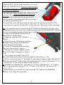
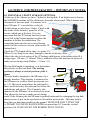
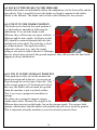
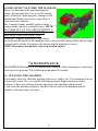
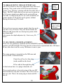
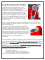
Manual for Maredo® MFrame 319-01
equipped with the MT200-REV 02
Verticut heads
Serial #:
IMPORTANT NOTE:
This machine cannot run by its own. It needs a (compact) tractor to drive it. An
experienced driver is required, alongside a well-equipped, safe tractor.
MAREDO DOES NOT TAKE ANY LIABILITY FOR TRACTOR OR DRIVER
DAMAGES WHO ARE TO BE BLAMED BY MISUSE OR MIS-CHOICE.
MAX. PTO REV. : 540 RPM
MAX GROUND SPEED : 8 KMH/ 5 MPH.
Note:
For a safe operation it is essential, that the operator reads and understands the manual of this MAREDO Machine and the tractor.
MAREDO BV, RIJKSSTRAATWEG 16, 3956 CR LEERSUM, NETHERLANDS.
WWW.MAREDO-BV.COM.
EN 1522
1
1.0 SAFETY INSTRUCTIONS.
1. Never disconnect or shortcut any of the safety devices.
2. Every MAREDO user must be fully informed and understand the safe
use of the MAREDO machine.
3. Inspect the ground, where the MAREDO machine is to be applied.
Remove loose obstacles, avoid uneven areas.
4. Drive carefully during work and during transport.
5. Ensure that other people are standing at least 4 mtr./ 12 ft. away
from the MAREDO machine during work and transportation.
6. The driver should use appropriate clothing. Wear strong shoes with
steel enforced toe caps, long trousers, gloves, tie up long hair and use
protection glasses for the eyes.
7. Choose the right tractor. Check with the required specifications.
8. Never overload the MAREDO. This is visible when the head starts to
vibrate or be unstable (going up and down).
9. Check the MAREDO minimal once a week, to ensure there are no
loose bolts and nuts. Check for damages too and repair them.
10. The MAREDO may never be used without protection covers and
safety decals.
11. Use only original MAREDO spare parts, in order to ensure the safe
operation of the machine.
12. Never use the MAREDO in the dark, in heavy rains, on frozen
grounds, stony conditions and/ or on slopes steeper than 30 degrees.
13. Maintain a log book of the repairs.
14. Be aware that changes made at the MAREDO, releases MAREDO
from CE regulations. You should homologate the machines yourself.
4 mtr/ 12 ft
4 mtr/ 12 ft
2
2.0 FOREWORD.
Congratulations with the purchase of your MAREDO® machine. To ensure the
safe and long lasting operation of this MAREDO® machine, you and anyone
else using this machine, should read and understand this user’s manual.
Also ensure that you understand and practice the safety rules, as described in
this manual.
This MAREDO®machine is delivered accomplished by a guarantee against
material and assembly errors. This guarantee applies for a period of 12
months, as from the date of purchase.
3.0 TECHNICAL SPECIFICATIONS.
Model
Working width
Working depth
Blades
Side to side spacing
Gearbox oil
Tractor size
PTO speed
Weight
: MFrame 319-01 plus MT200-02 verticut heads (3).
: 1900 mm/ 76”.
: 0 -25 mm/ 0- 1.0”.
: Carbide tipped blade thick 2.3 mm/ 0.09”.
: 30 mm./ 1,18”.
: SAE 80/90 W.
: 25 HP with 3Point CAT1 500 kg/ 1100 lbs lift capacity.
: Max 540 rpm.
: Complete machine: 365kg/ 800 lbs
4.0 EU- DECLARATION.
We, MAREDO, Rijksstraatweg16, 3956CR. Leersum, Holland, hereby declare
fully on our authority, that the product:
MAREDO® Mframe 319 equipped with MT200 verticut heads, with serial
number as indicated on the machine and in this manual, to which this
declaration applies, has been manufactured in line with NEN-EN –ISO 141211:2007, according to the stipulations of The Machine Directive 2006/42/EG.
Marinus Reincke Maredo BV Holland.
3
5.0 UNPACKING AND FIRST SET-UP:
The MAREDO machine is delivered on a specially
prepared steel pallet, at which the heads and the MFrame
are firmly packed. Assemble the machine as follows:
5.1. Remove all items from the pallet. Unscrew the rear
draw bar from the MFrame. In the end you should have the
following parts available: 3 x heads (RH, LH and rear one),
1x MFrame, rear draw bar, 2x PTO’s for RH and LH head ,
1 half PTO shaft for rear head, 1 x tractor PTO and 2 x
tube clamp d=80 mm (3”) to fix the PTO to the side heads.
5.2. Put the MFrame with “it’s nose” on the floor.
5.3. Mount the rear draw bar with the 3 bolts, which go
through the rubber pivot block. Put the self-lock nuts at
the rear side and tighten all 3 bolts well.
5.4. Connect the chain with D shackles at each side of the
rear draw bar. Tighten the D shackles well.
NOTE: Set the chain length at maximum. It can be
shortened later on when the rear head is too close to the
ground, when raised.
5.5. Put the MFrame on its storage stands on the floor.
5.6. Mount the rear head first. The PTO is already premounted at the head side. Insert the other PTO half into
this one and next slide+ secure the PTO to the rear PTO
shaft of the MFrame. If the PTO is in place, mount the
rear head to the rear draw bar of the MFrame with the 5
rubber blocks. Tighten all nuts (5) well.
5.7. Finally mount the two push-bars and the rear head is
in place.
5.8. We continue with mounting the side heads to the
MFrame. This goes as follows:
4
Mount the PTO with the long extension cover to the
heads first. IMPORTANT: when the extension cover
is secured with the tube clamp, be sure the hole in
the cover faces upwards.
Next insert the other PTO half and connect that side
to the MFrame. Again with the hole in the cover
facing up. Next mount the head to the MFrame.
Remove the pivot bolt and also the notch bolt.
Slide the head in place and tighten the pivot-bush
bolt and the notch-bolt well.
Do exactly the same with the head at the other side. Be sure the holes in the PTO
covers face also upwards, like the PTO on the first side. That helps with the greasing.
5.9. It is important that the correct tractor PTO length is determined. Not only when
the machine is new, but every time another tractor is used for this MAREDO machine.
The way to calculate the correct length goes as follows:
A- connect the MAREDO machine to the
tractor in the 3 Point linkage.
B- Adjust the top-link so the Aframe is
vertical.
C- Move the tractor 3P-hitch up and down
and find the position at which the PTO
shaft is the shortest in length.
D- Fix the 3 Point hitch at this position
and secure the machine + tractor.
E- Measure the (orange) length between
the two PTO shafts from groove- groove
(=L1).
F- Next measure the length of the PTO
drive shaft from secure pin to secure pin with the shaft fully in (= L2) .
G- If L2 is at least 50 mm or 2” less than L1, no action is required. If not take the PTO
shaft apart and each PTO half (steel tube and plastic cover) must be shortened: L2 –L1
+ 50 mm (or 2” if you work in inches with L1 and L2).
H- Example: We measured L1= 500 mm (20”) and L2= 600 mm (24”). L2 is more
than L1, so we need to cut it by L2 -L1 +50 mm = 600-500+50= 150 mm (or 2420”+2”= 6”).
I- Deburr all the parts, fix the PTO and mount the PTO shaft to the MAREDO
machine. He is ready for usage now.
5
6.0 (FIRST) JOB PREPARATION + IMPORTANT NOTES.
6.1 TOPLINK & 3-POINT LINKAGE SETTINGS.
At the top of the Aframe we have 3 holes for the top link. If an higher one is chosen,
the MAREDO machine will be tilted more forwards when raised. Which means more
clearance for the rear head. A clearance of at
least 200 mm/ 8” is needed for a safe job.
At the bottom we also have 3 holes. Check with
the stroke of the bottom 3 point bar of the
tractor, which one is the best. It is very
important that the 3P bottom bars have some
travel left in the bottom position to allow the
machine to follow the undulations The
connecting pins can also be reversed facing
inside (in case we have a tractor with narrow 3P
bottom bars).
Check the PTO length all the time, see point 5.9.
When it is too long or too short, damage to the driveline may occur.
Adjust the side-to-side swing of the 3P linkage stabilisators at the tractor side till it
swings appr. 150 mm./ 6” in total. This is needed to allow the machine & tractor to
make curves during work (Radius > 2.0 mtr./ 6’).
The top-link length is important, as it determines
the pressure on the rear head. The starting
A Frame
M Frame
position is always a vertical position of the A
frame.
The rear head is mounted to the MFrame via a
triangle drawbar. This drawbar is connected to
Top link
the MFrame via a rubber block pivot point (see
pt. 5.3).This pivot point allows the rear head to
move in all necessary direction and to follow the
3P Bottom bar
undulations and curves. The A frame is also
mounted to the MFrame via a rubber pivot point.
This allows the tractor to make curves during
work. If the Aframe plus the MFrame is pushed backwards by enlarging the top link,
more pressure is put on the rear head via the rubber pivot points. This may help to
keep the rear head more stable on the ground. HOWEVER DON’T PUSH THE
A_FRAME TOO MUCH BACKWARDS (no more than 10° from the vertical
position) AS IT MAY HURT THE RUBBER PIVOT POINTS.
6
6.2 DEPTH SETTING.
You have two depth adjusters at each head. They can be adjusted by hand. Unscrew
the (blue) top nut first. Next the second spoke-nut can be turned. The front roller will
move up and down. At the side you can see
the (theoretical) depth of the blade under the
front-roller-rear-wheel-plane.
NOTES:
A- Set both sides at the same depth.
B- Do NOT adjust one side more than 10 mm/
½” before compensating the other side first.
C- If the (blue) lock nut it tight, “unscrew” it
by turning the spoke nut first.
D- After the depth setting is done, tighten the
(blue) top nut to secure the setting.
6.3. UNLOCK THE AFRAME.
By removing the pin in the centre of the
Aframe, the A frame is unlocked from the
main chassis and is able to turn left and
right. This free movement is necessary to
allow the tractor & machine to make a
curve during work.
After work it is essential to put the lock pin
back in position, so the Maredo machine
does not swing behind the tractor.
When unlocked put the pin in the storage
hole.
6.4. START EN STOP PROCEDURES.
6.4.1 Inspect the area that you want to treat. Remove loose objects. Refrain from
using the machine in the dark, in heavy rains, on frozen grounds, stony
conditions and/ or on slopes steeper than 30 degrees
6.4.2 Gently drop the MAREDO machine till 100 mm/ 4” above the ground.
6.4.3 Engage the PTO and increase the engine revs till the PTO runs appr. 400 revs.
6.4.4 Lower the machine gently in the ground. DON’T LET IT BOUNCE.
6.4.5 Start moving forward. The speed depends on the depth setting and the ground
conditions. Start with appr. 3 km/h (2 mph). Max speed is 8 km/h (5mph) or when one
of the heads get unstable. Reduce the groundspeed at that moment immediately.
6.4.6 You can make curves, as long as they aren’t tighter than a radius=2.00 mtr./ 6’.
6.4.7 At the end of the pass raise the heads and disconnect the PTO at the same time.
6.4.8 Turn around and start another pass in the same way as described above.
7
6.5 LOCK UP THE HEADS TO THE MFRAME
Standard the heads can individually follow the undulations via the front roller and the
rear wheels. This is possible because the heads are flexibly mounted with rubber
blocks to the Mframe. The heads can be fixed to the MFrame for two reasons:
6.5.1 FIX IT IN THE WORK POSITION.
The heads can be fixed in the work position if
e.g. the heads are unstable in following the
undulations. If we lock the heads to the
MFrame, they will become one piece with the
MFrame and be more stable. An R pin (or bolt
M5) should be mounted through the tube hole
and the hole in the shaft. The push bar is fixed
as of that moment. The depth can still be
adjusted in the same way, only the actual
setting is not what is read at the decal. Although
the rear wheels may not touch the ground anymore, they still prevents the head from
digging in (deep) undulations.
6.5.2. FIX IT IN THE STORAGE POSITION.
If the push bar is fully out (at the moment the
heads are raised and in the air), we can put an
R pin through the rod in front of the tube. This
is for storage purposes. If the heads are locked
this way, the blades will not touch the ground
when the machine is put at a (hard) surface.
This is one way to prepare the machine for
storage.
The other one is using the support storage
stands and is better. Because the weight of the
MFrame does not rests on the heads, but on the storage stands. You can use both
options, which makes that the blades with carbide tips will never touch the ground.
This is important when the machine is stored on a hard (concrete) floor.
8
6.6 DISCONNECT & STORE THE MACHINE.
Before we disconnect the machine from the
tractor, the machine has to be set in the storage
mode. If that isn’t done properly, damage to the
machine and blades may occur, especially on
hard (concrete) surfaces.
The 3 support stands should be placed in the
storage mode, which is vertically down. NOTE:
BE CAREFULL AS YOU ARE ENTERING A
DANGEROUS AREA AROUND THE
MACHINE AND THE TRACTOR.
When the 3 support stands are in the correct
secured(vertical) position, the machine can be driven to the storage place and be gently
lowered on the stands. Disconnect the tractor and the machine is stored.
NOTE: Disconnect the machine only on a levelled surface.
7.0 MAINTENANCE.
This MAREDO Machine is a low maintenance machine. Most bearings are sealed and
do not need re-greasing. The following maintenance is needed:
.
7.1. CLEANING THE MACHINE.
We strongly advise to clean the machine after every (daily) job. Use compressed air or
low pressure water. Be very careful with high pressure/ high temperature water
cleaners, as they may damage the moving parts in the machine and the paint.
If you clean the machine regularly, the dirt will not stick to the machine and the
machine will work better next time.
9
7.2 GREASE POINT/ GREASE INTERVALS .
All 4 PTO shafts are the most important items that need
greasing. They need a shot of EP (Extreme Pressure)
grease every 10 hours, starting with the first shot after 4
hours. The PTO shafts that we use are easy to grease as
all (4) grease nipples per shaft can be accessed from
one side. As long as the PTO’s are well assembled, all
grease nipples of all 4 PTO can be grease without
having to rotate any PTO shaft.
Next we have two more grease nipples that also need
one shot every 50 hours. They are located under the
MFrame and grease the two front pivot points of the
two front units.
Also grease the depth adjusters by 1 shot every 50
hours
4 grease
nipples
per PTO
IMPORTANT
Align all grease
nipple of all the
PTO shafts
7.3 OIL CHECK AND REPLACEMENT.
There are two gearboxes mounted on this MAREDO machine. Both use the same
gearbox oil SAE 80/90W. The first time the oil need to be replenished after 100 hours
of use, after that it will be every 300 hours or once a year.
The main gearbox is mounted on the MFrame and
drives all the 3 different heads.
Check the oil level at this plug
(in the middle at the front)
Fill or add oil through this plug
At the bottom there is a plug to drain the oil.
The second gearbox is located on top of the rear MT
head and drives only the rear head. The oil level sit at
the rear side. This is the same plug to drain and fill
the oil.
10
7.4 COG BELT TENSION & REPLACEMENT.
The toothed belt (cog belt) tension is very important.
It determines the life time and the power it can
transmit. Each individual head has its own toothed
belt, who have to be checked independently.
The easiest way to figure out if the belt tension is right
is by putting a pin d=5 mm through the hole in the
side of the cog belt housing (if it isn’t there, remove
the top cover and work from the inside). If a force of
90 N ( 20 lbs) is applied halfway the belt side, the belt
should move 4.8 mm (0.19”). That works in both
directions (in or out), as long as the force is applied
square to the belt.
Maredo is working on a precision tension-measuring tool to easily check the belt
tension. When this tool will be available, we will update you. For now it has to be
done as described above.
If you need to adjust the belt tension, first push the PTO
extension cover back. Next loosen the two main nut one
turn. Finally adjust the tension with the nut at the bottom
of the threaded shaft. Don’t make large adjustments, you
only need fine tuning turns. Also take into account that the
belt tension may change at the moment the two main nuts
are tightened again. Don’t forget to tighten them anyhow
as the belt may get seriously damaged, due to
misalignment.
If a new belt must be installed, loosen the top pulley assemble bolt. Next screw the nut
upwards, so the top pulley drops. CHECK if all the pulley grooves are clean. Slide the
new cog belt on. NEVER USE force. Next start tensioning the belt as described above.
Turn the input shaft a couple of times (10) around and check the tension again. If okay
mount the top cover and finish the job. RE-CHECK the tension after one day of use.
NEVER replace the cog belt with a standard one. The Maredo ones can transmit
much more power than the standard one on the market place.
The toothed (cog) belt may crack because of:
- Not correctly mounted.
- Tension not correctly checked and maintained
- Overload, especially when the heads start bouncing.
It also acts as a safety device, in case a large object is hit.
11
8.0 REPAIR & REPLACEMENT.
8.1 REPLACEMENT OF THE BLADES.
In case the carbide tipped blades are worn out, they
need to be replaced as follows:
= Clean the head and put it firmly on the side.
= De-tension the cog belt and remove this belt.
= Take the front roller adjuster apart and turn the
front roller + frame backwards.
= Remove the small toothed belt pulley. Note this
is a taperlock system. Remove the two Allen
screws and put one in the center hole. Tighten it
and the taperLock will come off.
= Remove the 2 x 3 bolts/ nuts from the 2 main
bearings
= The whole shaft with blades can be removed.
= Next remove only the bearing at the pulley side.
= Unscrew the main nut that tightens all blades.
NOTE because Loctite has to be used to lock
the nut, you may need to heat the nut till 80 °C.
The Loctite will soften and you will be able to
remove the nut.
= Slide all blades + distance bushes of. Don’t mix
up the bushes at the start and end. Carefully lay them aside.
= Start to assembly the new blades with the distance
bushes. NOTE the blades should be mounted
in a spiral and in the right direction, like is shown in the picture.
= Use Loctite for the main nut. Tight is heavily.
= Mount the main bearing back on and assemble the complete shaft back in the
chassis.
= Assemble the pulley again. The two Allen screws of the taperlock should be back in
the two outer holes. Tighten them one-by-one up to 20 Nm/ 14.5 ft lb. Check this after
10 hours of usage.
= Assemble the timed belt and tension it like described under 7.4.
9.0 SPARE PARTS.
For a complete overview of all parts for this MAREDO® machine, please look at our web site
under support (www.maredo-bv.com/wp-content/themes/maredo/design/support/MT20002Verticutter spare part page). The two most important parts are:
1838220 Carbide tipped blade for MT200 verticutter
(20 per head, 60 = full set)
4023102 Toothed (cog) belt
12