1
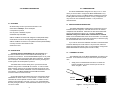
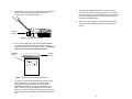
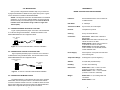
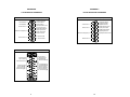
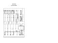
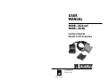
USER
MANUAL
MODEL 2020 and
MODEL 2020N
Interface Powered
RS-232 to V.35 Converters
Part #07M2020-D
Doc #077011UD
Revised 11/6/97
CERTIFIED
An ISO-9001
Certified Company
1.1 RADIO AND TV INTERFERENCE
The Models 2020 and 2020N generate and use radio frequency
energy, and if not installed and used properly--that is, in strict
accordance with the manufacturer's instructions--may cause
interference to radio and television reception. The Model 2020/2020N
has been tested and found to comply with the limits for a Class A
computing device in accordance with the specifications in Subpart J of
Part 15 of FCC rules, which are designed to provide reasonable
protection from such interference in a commercial installation.
However, there is no guarantee that interference will not occur in a
particular installation. If the Model 2020/2020N does cause
interference to radio or television reception, which can be determined
by disconnecting the RS-232 or V.35 interface, the user is encouraged
to try to correct the interference by one or more of the following
measures: moving the computing equipment away from the receiver,
re-orienting the receiving antenna, and/or plugging the receiving
equipment into a different AC outlet (such that the computing
equipment and receiver are on different branches).
1.2 CE NOTICE
The CE symbol on your Patton Electronics equipment indicates
that it is in compliance with the Electromagnetic Compatibility (EMC)
directive and the Low Voltage Directive (LVD) of the Union European
(EU). A Certificate of Compliance is available by contacting Technical
Support.
1
2
2.0 GENERAL INFORMATION
3.0 CONFIGURATION
The Model 2020/2020N is designed to be easy to use. In most
cases you will not need to configure the Model 2020/2020N in any
way: just plug it in and go! The Model 2020 is transparent to protocol,
including data rate and clocking method. the only configuration you
may need to do is for DTE/DCE orientation. This procedure is
described below.
2.1 FEATURES
3.1 SETTING DCE/DTE ORIENTATION
• Bi-directionally converts synchronous RS-232 to V.35
• Data rates to 384 Kbps, full or half duplex
• Transparent to protocol
• No AC power or batteries required
• DCE/DTE strap selectable
• DB-25 and M/34 connectors with integral 6 ft cable (Model 2020)
• Dual DB-25 connectors with integral 6ft cable (Model 2020-25)
The Model 2020/2020N installs between DTE devices such as
terminals and host computers, and DCE devices such as modems,
multiplexers and CSU/DSUs. Most often the DTE device will be RS232, and the DCE device will be V.35. Therefore, the default
DCE/DTE setting for the Model 2020 is RS-232 DCE to V.35 DTE,
based on how the Model 2020 "sees" its own orientation. For example,
if the Model 2020 sees its own RS-232 port as DCE, it will want to plug
into an RS-232 DTE device such as a terminal.
• DB-25 and M/34 connectors in one plastic enclosure (Model 2020N)
• Circuitry housed in ultra-miniature case
• Made in the USA.
If you need to reverse the DCE/DTE orientation of the Model 2020
so that the RS-232 port is DTE and the V.35 port is DCE, follow the
step-by-step instructions below (note: it is not possible to configure the
Model 2020/2020N so that both ports are DTE or DCE).
2.2 DESCRIPTION
The Model 2020 and 2020N RS-232 to V.35 converters let a
synchronous RS-232 device communicate bi-directionally with a
synchronous V.35 device. The Model 2020/2020N require no AC power
or batteries to operate and supports data rates to 384 Kbps. Operating
full or half duplex, the Model 2020 passes all necessary clocking and
control signals, and is transparent to protocol.
The Model 2020 connects directly to the synchronous RS-232
interface using a male or female DB-25 connector. A male or female
M/34 connector at the end of an integral 6 ft cable plugs into the V.35
device. The Model 2020-25 substitutes a male or female DB-25 on the
V.35 interface. The Model 2020N house both DB-25 and M/34
connectors within the same enclosure.
An internal DCE/DTE strap allows the user to configure the Model
2020/2020N as "DCE to DTE" or "DTE to DCE". In most cases, this
eliminates the need for special crossover cables. Housed in an ultraminiature case measuring only 2.66" x 2.10" x 0.73", the Model 2020
fits easily into tight locations. The Model 2020N measures a tiny 3.20”L
x 2.10”H x 0.90”W.
3
3.1.1 OPENING THE CASE
The DCE/DTE strap on the Model 2020/2020N is located on the
PC board. To access the PC board you will need to open the plastic
case.
1.
Simply insert a small flathead screw driver or similar tool
between the DB-25 connector and the lip of the case as
shown in Figure 1, below.
RS-232
Interface
Figure 1. Inserting the screw driver
4
2.
Gently twist the screw driver to pop the case open as shown in
Figure 2, below. Be careful not to damage the case or
connector as you twist the screw driver.
5.
To reverse the DCE/DTE orientation, pull the entire green
strap out of its socket and rotate it 180 degrees. Then plug it
back into the socket. You will see that the arrows on top now
point in the opposite directions, showing the new DCE/DTE
orientation of the Model 2020.
6.
When you're done, realign the case halves (don't forget the
captive screws and saddle washers) and snap them back
together.
RS-232
Interface
Figure 2. Popping open the case
3.
Once you have opened the case of the Model 2020/2020N,
you will see the green DCE/DTE strap located on the PC
board in the position shown in Figure 3, below. The DCE/DTE
strap is oriented closest to the RS-232 interface.
DCE/DTE
Strap
RS-232
Interface
DCE
DTE
Figure 3. DCE/DTE strap orientation on PC board
4.
The arrows on top of the strap indicate the orientation of the
Model 2020's ports. For example, if the "DCE" arrow is
pointing toward the DB-25 connector, then the Model
2020/2020N's strap is set so that it sees its DB-25 port as
DCE. It wants to plug into the DB-25 port of a terminal or
other DTE. The arrow pointing toward the cable at the rear of
the PC board shows the orientation of the Model 2020's V.35
port.
5
6
4.0 INSTALLATION
APPENDIX A.
After you have configured the DCE/DTE strap, all you need to do
is plug the Model 2020 or 2020N into the proper device ports. Figures
4 and 5 showhow to intstall the Model 2020/2020N.
*NOTE: The diagrams below show the Model 2020 in the installed
application. If you are using a Model 2020N, connect the RS-232
interface directly to the RS-232 equipment and connect the V.35
interface to the V.35 interface using a cable no longer than
164 feet (50m).
MODEL 2020 AND 2020N SPECIFICATIONS
Interfaces:
EIA RS-232/ITU/CCITT V.24 to ITU/CCITT
V.35/EIA RS-530
Data Rates:
0 - 384 Kbps
Transmission Mode:
Synchronous, full or half duplex
Protocol:
Transparent to protocol
Clocking:
Set by connected devices
Connectors:
All Versions: DB-25 male or female on
RS-232 side;
Model 2020: M/34 male or female on V.35
side at the end of 6 ft. cable.
Model 2020-25: DB-25 male or female on
V.35 side at the end of 6 ft. cable.
Model 2020N: RS-232 Male with M/34
male or female on V.35 side OR, RS-232
female with M/34 male.
Power Supply:
None required. Uses power from NIC data
and control signals
Temperature Range:
0-60 degrees C (32-140 degrees F)
Altitude:
0-15,000 feet (0-5,000 meters)
Humidity:
5 to 95% noncondensing
Dimensions:
Model 2020: 2.66"L x 2.10"H x 0.73"W
(6.76cmL x 5.33cmH x 1.85cmW)
Model 2020N: 2.40”L x 1.73”H x 0.89”W
(6.10cmL x 4.39cmH x 2.26cmW)
Weight:
Model 2020: 14 oz, including cable and
connectors
Model 2020N: 2.2 oz
4.1 CONNECTING AN RS-232 DTE TO A V.35 DCE*
Figure 4 (below) illustrates proper connection of an RS-232 DTE
to a V.35 DCE using the Model 2020. The RS-232 interface of the
Model 2020/2020N must be configured as DCE.
Sync. Terminal
(DTE)
V.35 Modem
(DCE)
Figure 4. A Common RS-232 DTE to V.35 DCE Installation
4.2 CONNECTING A V.35 DTE TO AN RS-232 DCE*
Figure 5 (below) illustrates proper connection of a V.35 DTE to
an RS-232 DCE using the Model 2020. The RS-232 interface of the
Model 2020/2020N must be configured as DTE.
V.35 Mini Computer
(DTE)
Sync. Modem
(DCE)
Figure 5. A common V.35 DTE to RS-232 DCE installation
4.3 CONNECTING THE MODEL 2020-25
The Model 2020-25 is connected the same way as the standard
Model 2020, with the exception that the V.35 interface has a DB-25
connector instead of an M/34 connector. The DB-25 carries the same
signals as the M/34, but is pinned according to the RS-530 Standard.
Please refer to Appendix B for specific pin out information.
7
8
APPENDIX B
APPENDIX C
V.35 INTERFACE STANDARDS
RS-232 INTERFACE STANDARDS
CCITT V.35/EIA-530 INTERFACE (DB-25)
1 - (FG) Frame Ground
2 - Transmit Data A
3 - Receive Data A
4 - (RTS) Request to Send
5 - (CTS) Clear to Send
6 - (DSR) Data Set Ready
7 - (SG) Signal Ground
8 - (CD) Carrier Detect
9 - Receive Clock B
Transmit Data B - 14
Transmit Clock A - 15
Receive Data B - 16
Receive Clock A - 17
Data Term. Ready (DTR) - 20
11 - External Clock B
12 - Transmit Clock B
External Clock A - 24
RS-232C/V.24 INTERFACE (DB-25)
1- (FG) Frame Ground
2- (TD) Transmit Data
3- (RD) Receive Data
4- (RTS) Request to Send
5- (CTS) Clear to Send
6- (DSR) Data Set Ready
7- (SG) Signal Ground
8- (DCD) Data Carrier Detect
Transmit Clock - 15
Receive Clock - 17
Data Term. Ready (DTR) - 20
External Clock - 24
CCITT V.35 Interface (M/34 Male)
B
Signal Ground -B
Clear To Send -D
Data Carrier Detect -F
F
L
R
Receive Data (A) -R
Receive Data (B) -T
Receive Timing (A) -V
Receive Timing (B) - X
V
Z
A
D
J
N
T
X
E
K
P
U
Y
BB
DD
H
M
S
W
AA
A- Frame Ground
C- Request to Send
E- Data Set Ready
H- Data Terminal Ready
KMP- Transmitted Data (A)
S- Transmitted Data (B)
U- Terminal Timing (A)
W- Terminal Timing (B)
Y- Transmit Timing (A)
AA- Transmit Timing (B)
CC
FF
JJ
C
LL
NN
EE
HH
KK
MM
9
10
DTR
DCD
DSR
CTS
RTS
TC
XC
RC
XC
TC
TC
XC
TD
RD
RD
TD
DATA
RS-232
RS-232
V.35
SWITCHING
REGULATOR
6
8
20
AND
5
+V
-5V
4
POWER SUPPLY
+5V
15
24
17
SG
FG
DTR
DCD
B
SG
FG
DTR
DCD
V.35
RS-232
DSR
CTS
RTS
AUGUST 12, 1994 REV. D
PATTON ELECTRONICS MODEL 2020 BLOCK DIAGRAM
7
A
H
20
1
F
8
4
6
5
X
V
W
U
AA
24
Y
AA
W
Y
U
15
15
24
T
2
S
P
R
T
S
R
P
3
3
2
E
D
C
DSR
CTS
RTS
V.35
RC-B
RC-A
XC-B
TC-B
XC-A
TC-A
TC-B
XC-B
TC-A
XC-A
TD-B
RD-B
TD-A
RD-A
RD-B
TD-B
RD-A
TD-A
APPENDIX D
BLOCK DIAGRAM