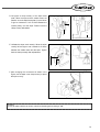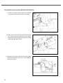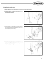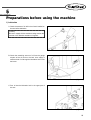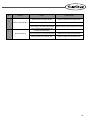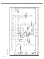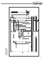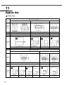
1
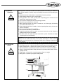
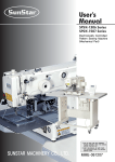
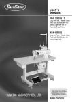
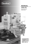
USER
MANUAL
SPS/D-B1201 SERIES
SPS/C-B1201 SERIES
Electronically Controlled
Bar Tacking
Sewing Machine
(Machine Parts)
1. For proper use of the machine,
thoroughly read this manual before use.
SUNSTAR MACHINERY CO., LTD.
2. Keep this manual in a safe place for
future reference in case the machine
breaks down.
MME-061221
lity
a
u
tQ
Besst Pricevice
Be st Ser
Be
1. Thank you for purchasing our product. Based on the rich expertise and
experience accumulated in industrial sewing machine production, SUNSTAR
will manufacture industrial sewing machines, which deliver more diverse
functions, high performance, powerful operation, enhanced durability, and
more sophisticated design to meet a number of user’s needs.
2. Please read this user’s manual thoroughly before using the machine. Make
sure to properly use the machine to enjoy its full performance.
3. The specifications of the machine are subject to change, aimed to enhance
product performance, without prior notice.
4. This product is designed, manufactured, and sold as an industrial sewing
machine. It should not be used for other than industrial purpose.
R
SUNSTAR MACHINERY CO., LTD.
Models of bar tacking sewing machines
1) With an electronic presser foot lifter
SPS / D - B 1 2 0 1 H
① Sunstar
Pattern
System
② Series Classification
A: Motor Belt-Type
B: Direct Drive Type
C: Upgraded Motor Belt-Type
D: Upgraded Direct Drive Type
③ Name of Bar Tacking
Sewing Machine
(BA)
Belt Loop
(For Belt Loop Attachment)
⑤ Hook Type
BL : Large Shuttle Hook
④ Material Type
H : For Heavy Materials
M : For General Materials
L : For Thin Materials
K : For Knit
2) With a pneumatic presser foot lifter
SPS / D - B 1 2 0 1 H A ① Sunstar
Pattern
System
② Series Classification
A:
B:
C:
D:
Motor Belt-Type
Direct Drive Type
Upgraded Motor Belt-Type
Upgraded Direct Drive Type
③ Name of Bar Tacking
Sewing Machine
④ Pneumatic Presser Foot
Lifting System
⑤ Classification of Presser Foot Lifting System
20: Monolithic Driven Presser Foot
22: Separate Driven Presser Foot
⑦ Hook Type
BL : Large Shuttle Hook
⑥ Options
W: Electronic wiper
TH: Upper thread
holding device
Table of contents
1. Safety rules for machine ..................................................................................................... 6
1-1) Machine Transportation ......................................................................................................... 6
1-2) Machine Installation ............................................................................................................... 6
1-3) Machine Repair ...................................................................................................................... 6
1-4) Machine Operation ................................................................................................................. 7
1-5) Devices for safety .................................................................................................................. 7
1-6) Location of Caution mark ...................................................................................................... 8
1-7) Contents of Caution mark .................................................................................................... 8
2. Specifications .......................................................................................................................... 9
3. Structure ................................................................................................................................. 10
1) Names of each machine parts ................................................................................................ 10
4. Installation .............................................................................................................................. 11
1) Machine installation conditions ............................................................................................... 11
2) Electric installation conditions ................................................................................................ 11
3) Safe installation of the tables .................................................................................................. 11
4) How to install the table (BA type) ............................................................................................ 14
5) The assembly of peripheral parts ............................................................................................ 16
6) Installation of air pressure specification (HA type) .................................................................. 17
7) Installation and control of the option wiper (HA type) .............................................................. 20
8) Installation of the vent hole [SPS/D(C)-B1201M (HP)] ............................................................ 22
9) Installing the needle cooler ..................................................................................................... 23
5. Preparations before using the machine ..................................................................... 25
1) Lubrication ............................................................................................................................... 25
2) Installation of the needle ......................................................................................................... 26
3) Routing the upper thread ........................................................................................................ 27
4) Placing the lower thread .......................................................................................................... 27
5) Installation and separation of the bobbin case ........................................................................ 27
6) Tension control of the upper and lower threads ...................................................................... 28
7) Winding the lower thread ....................................................................................................... 28
8) Operation of the pedal (H, M, L, K types) ................................................................................ 29
9) Operation of the pedal (HA type) ............................................................................................ 29
10) Disposal of the waste oil ....................................................................................................... 29
11) Input of the compressed air and control of the air pressure (HA type) .................................. 30
12) Control of the upper thread holding device (optional) ........................................................... 30
6. Maintenance and repair .................................................................................................... 31
1) Adjustment of the needle bar height ....................................................................................... 31
2) Adjustment of the needle and the shuttle ................................................................................ 31
3) Adjustment of the lower shaft gear and the shaking shaft gear .............................................. 32
4
4) Adjustment of the position of the shuttle upper spring ............................................................ 32
5) Adjustment of the presser foot height ..................................................................................... 33
6) Adjustment of thread release-related parts ............................................................................. 33
7) Adjustment of wiper-related parts ........................................................................................... 35
8) Adjustment of trimming-related parts ..................................................................................... 35
9) Adjustment of the main thread adjustment device .................................................................. 38
10) Adjustment of the bobbin winder ........................................................................................... 38
11) Positioning of the synchronizer (C-Series) ............................................................................ 39
12) Installation and control of the direct drive motor (D-Series) .................................................. 39
13) Setting up the X-Y origin ...................................................................................................... 40
14) Adjustment of the vent hole device [SPS/D(C)-B1201M (HP)] ............................................. 41
15) When the vent hold device is not used [SPS/D(C)-B1201M (HP)] ........................................ 41
16) Adjusting and operating the needle cooler ............................................................................ 41
7. Cause of troubles and troubleshooting ..................................................................... 42
8. Pattern list .............................................................................................................................. 44
9. Table drawing ........................................................................................................................ 45
1) SPS/D-B1201 .......................................................................................................................... 45
2) SPS/C-B1201 .......................................................................................................................... 46
3) SPS/D-B1201M(BA) ............................................................................................................... 47
10. Gauge list ............................................................................................................................. 49
11. Option list ............................................................................................................................. 50
12. Circuit diagram of air pressure system (HA type) ............................................... 53
1) SPS/D(C)-B1201HA-20 ........................................................................................................... 53
2) SPS/D(C)-B1201HA-22 ........................................................................................................... 54
5
1
Safety rules for machine
Safety instruction on this manual are defined as Danger, Warning and Notice.
If you do not keep the instructoins, physical injury on the human body and machine damage might be occurred.
DANGER : This indication should be observed definitely. If not, danger could be happen during the installation,
conveyance and maintenance of machines.
WARNING : When you keep this indication, injury from the machine can be prevented.
CAUTION : When you keep this indication, error on the machine can be prevented.
1-1) Machine
Transportation
Only trained and experienced people should treat the machine who are fully
understand the safety rules. For conveyance, follow the below directions.
ⓐ More than two people to a minimum should convey the machine.
ⓑ For a protection of safety accident, wipe away the oil stained on machine.
Danger
1-2) Machine
Installation
Caution
Owing to the improper environment for machine installation, physical damages on the
human body and machine can be occurred. Please follow below conditions.
ⓐ When you unwrap the packing of the machine, try from above in order. Especially
careful of nails put into edges of wood box packing.
ⓑ Since dust and humidity can cause pollution and abrasion, you should install
airconditioner with regular cleaning.
ⓒ Put in a place of no direct ray of light. If the machine is exposed in direct ray of light
for a long time, transformation of color and shape can be happened.
ⓓ To get enough space in case of repair, make the machine 50cm apart from the right
and left and back side of wall to a minimum.
ⓔ EXPLOSION HAZARDS
Do not operate in explosive atmospheres. To avoid explosion, do not operate this
machine in an explosive atomosphere including a place where large quantities of
aerosot spray product are being used or where oxygen is being administered unless
it has been specifically certified for such operation.
ⓕ The machines where not provided with a local lighting due to the feature of machine.
Therefore the illumination of the working area must be fuifilled by end user.
[Note] Details for installation of machine is described in‘4. Machine Installation.’
1-3) Machine Repair
Danger
6
If you have any problems on the machine, troubleshooting should be handled by the
designated A/S engineers.
ⓐ Before cleaning and repairing machine, cut off the main power and wait for 4 minutes
until the machine comes to be completely discharged.
ⓑ You should not change the specification of machine and any part of machine without
consulting with our company. Those changes can threaten the safety of machine during
the operation.
ⓒ You should exchange from the used one into SWF guaranteed devices.
ⓓ After finishing troubleshooting, cover the all covers that are uncovered during repairing.
1-4) Machine
Operation
Caution
SPS/D(C)-B1201 series are intended for industrial purposes for bar tacking on textiles and
other similar materials. Carefully study the following instructions before operating the
machine.
ⓐ Read the manual to understand on the operation of machine perfectly.
ⓑ Wear suitable clothes and cap for safe operation.
ⓒ During operation, don’t make you body close to operating part of machine such as
needle, hook, take-up lever or pulley.
ⓓ Do not remove a safety plate and covers during operation
ⓔ Be sure the grounding lines in connected.
ⓕ Before opening electricity box such as control box, cut off the supply of electricity
and confirm if the switch is“off”.
ⓖ When inserting thread into a needle or before inspecting after sewing, be sure the
machine is stopped.
ⓗ Do not turn on the power during pedaling.
ⓘ Do not use several motor per a electric outlet.
ⓙ Install the machine apart from noise occurrence area such as high frequency
welding machines as far as possible.
ⓚ Be careful- When the upper feed plate comes down to press. Otherwise, the finger
or hand hight be hurt at smacking.
[Caution]
Always start the machine with safety covers in place since fingers or hands could be
injured or cut off by the belt. Turn off the power switch when conducting a regular check
on the machine.
1-5) Devices for
safety
Caution
ⓐ Safety label : It describes cautions during operating the machine.
ⓑ Thread take-up cover : It prevents from any contact between body and take-up lever.
ⓒ Motor Cover(D Series) : It prevents from insertion of hands, feet or clothes by Motor.
Belt Cover(C Series) : It prevents from insertion of hands, feet or clothes by V-belt Motor.
ⓓ Label for voltage specification: Safety instructions to prevent possible electric shocks.
(Voltage and Hz)
ⓔ Finger guard : It prevent from contacts between a finger and needle.
ⓕ Safety plate : It protects eyes against needle breaks.
ⓒ
ⓑ
ⓐ
ⓕ
ⓔ
ⓓ
7
1-6) Location of
Caution mark
CAUTION
경 고
Caution mark is attached on the machine for safety. Read the directions of the Caution
mark carefully before running the machine.
[Location of caution mark]
Do not operate without finger guard and
safety devices. Before threading, changing
bobbin and needle, cleaning etc. switch off
main switch.
손가락 보호대와 안전장치 없이 작동하지
마십시오.
실, 보빈, 바늘교환시나 청소전에는 반드시 주
전원의 스위치를 꺼 주십시오.
CAUTION
경 고
Hazardous voltage will cause injury.
Be sure to wait at least 360 seconds before
opening this cover after turn off main switch
and unplug a power cord.
고압 전류에 의해 감전될 수 있으므로 커버를
열 때는 전원을 내리고 전원 플러그를 뽑고 나
서 360초간 기다린 후 여십시오.
1-7) Contents of
Caution mark
Caution
1)
CAUTION
경 고
Do not operate without finger guard
and safety devices. Before threading,
changing bobbin and needle, cleaning
etc. switch off main switch.
Caution
손가락 보호대와 안전장치 없이 작동하지 마
십시오.
실, 보빈, 바늘교환시나 청소전에는 반드시
주전원의 스위치를 꺼 주십시오.
2)
CAUTION
경 고
Hazardous voltage will cause injury.
Be sure to wait at least 360 seconds
before opening this cover after turn
off main switch and unplug a power
cord.
고압 전류에 의해 감전될 수 있으므로 커버
를 열 때는 전원을 내리고 전원 플러그를 뽑
고 나서 360초간 기다린 후 여십시오.
8
2
Specifications
SPS/D(C)-B1201
Model
HA
HA-BL
Sewing area
Sewing speed
H
H-BL
M
M-BL
X: 40mm,
Max. 2,200spm
L
K
Y: 20mm
Max. 2,700spm
Max.
Max. 2,000spm
Stitch length
0.1~10mm
Feeding system
Feeding by stepping pulse motor
Needle bar stroke
41.2mm
Hook used
Standard Large Standard
Large
Standard
Large
shuttle hook shuttle hook shuttle hook shuttle hook shuttle hook shuttle hook
Needle used
DP×17 #23
Presser foot height
Max. 20mm
Trimming device
Wiper
DP×17 #19
M(HP)
14
M(BA)
X:40mm
Y:20mm
Max. 2,700spm
Max. 2,700spm
(2,000spm)
Standard shuttle hook
DP×5 #16(#14)
DP×5 #11
DP×5 #16
DP×5 #16
(#14)
Max. 17mm
Installed
Optional
Installed
No of stitches
Max. 10,000 stitches
No of patterns
Max. 99 patterns (Standard: 32 patterns)
Memory
P-ROM
Enlargement/Reduction
Main motor
20%~200%
D Series
Direct drive AC Servo Motor
C Series
550W AC Servo motor
Main motor
Power consumption
600VA
Optimal temperature for
machine operation
5°C~40°C
Optimal humidity for
machine operation
20%~80%
Voltage
1-Phase: 100~240V
3-Phase: 220~440V, 50/60Hz
Air pressure
0.49MPa
(5kgf/㎠)
9
3
Structure
1) Names of each machine parts
Arm
Thread Spool
Stand
Safety Plate
Operation Box
Power Switch
Pedal Switch
10
4
Installation
1) Machine installation conditions
A. Do not use the machine where the voltage is over or under 10% of the rate current to prevent accidents.
B. For safe operation, use the machine under the following conditions.
Room temperature when the machine is in use: 5℃~40℃
Room temperature when the machine is not in use: -10℃~60℃
C. Humidity: 20~80% (relative humidity)
2) Electric installation conditions
A. Voltage
The voltage must be between within ± 10% of the rated current.
The frequency must be within 1% range of the rated current frequency (50/60Hz)
B. Electromagnetic waves
Use separate power for products with strong electromagnetic waves or high frequency. Keep the sewing machine
away from them.
C. Always use low voltage when mounting accessories or supplementary devices on the control box.
D. Do not spill water or coffee into the control box or motor.
E. Do not drop the control box or motor.
3) Safe installation of the tables
A. Fix the oil tub holder①, oil tray②, control box③ and
power switch④ onto the table.
B. Attach the bed cushion rubber① to the table.
①
②
[Figure 1]
[Figure 2]
C. In case of SPS/D-B1201 series, attach the safety
switch supporting rubber① to the table.
①
[Figure 3]
11
D. Attach the hinge metal and the hinge rubber on the
bed. Insert a fixing bolt into the hinge metal hole at
point① and fix it onto the table.
[Danger]
At least two or more people should move the
machine for safety.
Fixing Bolt
Hinge Rubber
①
Hinge
[Figure 4]
E. Set the machine in the upright position as described in
the Figure. Insert the fixing bolt into the hinge hole at
point① and fix it onto the table.
[Danger]
Since the machine is not fully installed onto the table at
this point, pay extreme caution when you set the
machine in the upright position.
①
Fixing Bolt
①
[Figure 5]
F. In case of SPS/D-B1201 series, assemble the safety
switch bracket ① on the bed as in the figure. Move the
safety switch bracket up and down to make sure that
the safety switch supporting rubber② is tightly
pressed by the safety switch③, and then fasten the
screw④.
①
②
④
③
[Figure 6]
12
G. While the machine is standing as shown in the Figure,
put the“V”- belt between the pulley and the motor.
(C-Series)
Pulley
V-Belt
Motor Cover
[Figure 7]
H. After connecting the V-belt, unfasten the fixing nuts①
and ② to give tension to the belt (D) by the weight of the
motor (C). Then tighten the nut① and ② consecutively.
(C-Series)
D
①
②
C
[Figure 8]
I. Be sure to connect the green grounding conductor that
links the motor to the machine. Connect the grounding
conductor wire between the control box and the motor.
(C-Series)
Grounding
Conductor
[Figure 9]
13
J. After connecting the cables between the machine and the control box, fix the cable wires under the table as
described in the Figure. (Adjust the length of the wires to ensure that there is a sufficient length when placing the
machine to the upright position.)
Table
[Figure 10]
4) How to install the table (BA type)
A. Fix the oil container support ①, the oil dish②, and
the control box ③ on the table (below).
B. Fix the power switch ④ on the table (above).
④
C. Assemble the bed cushion rubber⑤ on the table
(below).
D. Assemble the safety switch support rubber⑥ on the
table (below).
②
①
③
⑥
⑤
[Figure 11]
E. Fix the table (above) and (below) as in the figure.
(115mm high)
Table (above)
Table (below)
[Figure 12]
14
F. Assemble the hinge and the hinge rubber on the bed,
and insert the adjusting bolt into the hinge hole at ①.
Then fasten it on the table (below) as in the figure.
Fixing bolt
Hinge rubber
①
Hinge
[Figure 13]
To prevent safety accident, the machine should be carried by at least two people.
Danger
G. Open the hinge area on the table (above) and erect
the sewing machine. Insert the fixing bolt into the
hinge hole at ① and fix it on the table.
①
Fixing bolt
①
[Figure 14]
The machine has not been completely assembled. When erecting the machine, make sure to prevent
the occurrence of a safety accident.
Danger
H. Assemble the safety switch bracket① on the bed as
in the figure. Move the safety switch bracket up or
down to adjust the safety switch support rubber② to
tightly press the safety switch③, and then fasten the
tightening screw④.
Table (above)
①
②
④
③
Table (below)
[Figure 15]
15
I. Complete the cabling connection between the machine and the control box and fix the cables below the table as in
the figure. (When the machine should be erected to fix the cables, set the length of the cables considering the
machine erection.)
Table (above)
Hinge
Table (below)
[Figure 16]
5) The assembly of peripheral parts
A. Attach the motor cover to the top (2EA) and bottom (2EA) of the back side of machine and sides by using fixing bolts.
(In case of C series, attach the belt cover by using fixing screws for the rear (3EA) and the side (2EA).)
Fixing Screw
Fixing
Screw
Motor Cover
Velt Cover
Fixing Screw
D-series
C-series
[Figure 17]
[Figure 18]
[ Caution ]
For safety, motor cover and safety plate should be attached to the machine.
B. Attach the safety plate to the backside of the arm.
C. Install the thread stand onto the table.
Faceplate
Safety Plate
Assembly
[Figure 19]
16
[Figure 20]
6) Installation of air pressure specification (HA type)
(1) How to assemble the filter regulator
Attach the filter regulator to the right side of the table leg with the bolts as shown in the Figure.
[Figure 21]
(2) How to assemble the solenoid valve
Fix firmly the solenoid valve to a proper location under
the table using the screws.
[Figure 22]
17
(3) How to connect the air hose of the monolithic driven presser foot
1. Connect the filter regulator and the solenoid valve
together with a hose①.
2. Insert the hoses with “S3F” and “S4F” labels into A
and B as shown in the Figure. Put in the hoses deeply.
3. Use the quick couplings② to connect S3L and S3R
and S4L and S4R.
4. Connect the solenoid and the power switch connector.
[Figure 23]
18
(4) How to connect the air hose of the separate-driven presser foot
Air Hose
Hose Nipple
Cap Net
1. Connect the filter regulator and the solenoid valve
together with a hose①.
2. Assemble the hoses with S3L, S4L, S3R and S4R
labels onto the solenoid parts as shown in the Figure.
3. Connect the solenoid and the pressure switch
connector. (Be sure to match the labels of the solenoid
and of the connectors.)
[Figure 24]
19
7) Installation and control of the option wiper (HA type)
A. Mount the wiper base plate with a screw as shown in
the Figure.
[Figure 25]
B. Fix the wiper base onto the opposite side with two
fixing screws as shown in the Figure.
[Figure 26]
C. Link the connector located at the solenoid with the
connector from the arm.
[Figure 27]
20
D. Un-tighten a clamp screw② of the wiper base
plate. When the wiper and the needle center are
parallel, move the wiper base plate③ up and down
to give a clearance of 14.5~15.5mm between the
needle plate① and the wiper. Fasten back the
clamp screw② afterwards.
②
①
③
[Figure 28]
E. Unfasten the wiper crank screw④. Move the wiper
crank⑤ left and right to set a clearance of 25mm
between the needle center and the wiper. Tighten
back the clamp screw④ after adjustments.
④
⑤
[Figure 29]
F. After arranging the connectors as shown in the
Figure, use the wiper cover clamp screw⑦ to place
the wiper cover⑥.
⑥
⑦
[Figure 30]
[Caution]
To use the wiper solenoid, set function code A-18 related to general sewing at “100”.
21
8) Installation of the vent hole [SPS/D(C)-B1201M (HP)]
A. Loosen four clamp screws and take out the bed
cover (right) from the bed as shown in the Figure.
Bed Cover(right)
[Figure 31]
B. Attach the vent hole device onto the bed and fix with
four clamp screws as illustrated in the Figure.
Afterwards, attach the table cover onto the vent hole
device using two clamp screws.
Table Cover
Vent Hole Device
[Figure 32]
C. Securely tie the solenoid cable and the sensor cable
of the vent hole device, with X and Y motor cables as
shown in the Figure.
Sensor Cable
Solenoid Cable
X and Y
Motor
Cables
[Figure 33]
22
9) Installing the needle cooler
A. Before installation, check if all the parts are in place as described in the Parts Book.
5~8mm
B. Insert the nozzle ① 5~8mm into the one end of the air
hose as shown in the figure.
①
[Figure 34]
C. Use the guide A ① and guide B ② to fix the nozzle ③
onto the guide bracket ④ as illustrated in the figure,
and fix temporarily with a screw ⑤.
①
⑤
④
②
③
[Figure 35]
D. Assemble the guide bracket ① assembled on the
nozzle, onto the lower fixing screw part ③ of the
faceplate, using a screw ②.
②
③
①
[Figure 36]
23
E. Use a screw ② to fix the speed controller ① onto the
speed controller bracket ③. Assemble it onto the arm
afterwards.
[Caution]
Be careful of the assembly direction of the speed
controller.
③
①
②
[Figure 37]
F. Cut off the lower hose of the presser foot-driving
cylinder. Connect it to the air hose of the needle
cooler, using the air fitting.
[Figure 38]
G. Link the hose with the left and right side of the speed
controller.
[Figure 39]
31.8
H. Fix the nozzle as shown in the figure and fix it firmly
with a screw.
[Figure 40]
24
5
Preparations before using the machine
1) Lubrication
A. Check the amount of oil left in the oil tank installed on
the arm before lubrication.
[Caution]
Be sure to supply oil if the machine is being used for the
first time or has been left unused for a long time.
[Figure 41]
B. Check the remaining amount of oil from the gauge
window of the oil tank on the bed, then supply a
sufficient level of oil through the lubrication hole on the
bed cover.
[Figure 42]
C. Pour oil into the lubrication hole in the upper part of
the arm.
[Figure 43]
25
D. Open the hook cover to supply oil until the shuttle
race ring is covered with oil. Place back the hook
cover after lubrication.
[Caution]
For safety, keep the hook cover on during machine
operation.
Shuttle Race Ring
Hook Cover
[Figure 44]
E. Supply silicon oil into the silicon oil tank mounted on
the right side of the arm.
Silicon Oil Tank
[Figure 45]
2) Installation of the needle
Loosen the needle fixing screw of the needle bar. Then,
with the needle groove facing the front, push the needle
until its upper end touches the needle hole of the needle
bar. Fix the needle in with the needle fixing screw.
Needle Fixing
Screw
Needle
[Figure 46]
26
3) Routing the upper thread
Place the thread take up lever at the highest position to hang the upper thread as shown in the Figure. As for the
thread guide of the needle bar, hang the thread as shown in the Figure ① for thick materials and the Figure ② for
general and thin materials.
↔ 40mm
Figure ②
Figure ①
[Figure 47]
4) Placing the lower thread
A. Insert the bobbin① into the bobbin case② as
illustrated in the Figure.
25mm
[Caution]
Insert the bobbin to turn clockwise when seen from
behind the bobbin case.
③
②
①
B. Pass the lower thread through a crack in the bobbin
case and then through a thread hole③.
C. Let the lower thread hang about 25mm from the
thread hole③.
[Figure 48]
5) Installation and separation of the bobbin case
Open the hook cover. Hold the knob① of the bobbin
case and push it into the shuttle until it makes a clicking
sound.
[Caution]
If you start operating the machine with the bobbin case
not fully installed, threads can get tangled or the bobbin
case can pop out.
Bobbin Case
①
[Figure 49]
27
6) Tension control of the upper and lower threads
A. Tension adjustment of the upper thread
Turn the nuts③ and ④ of the main thread adjusting
device① and the auxiliary thread adjusting device②
in a clockwise direction for stronger tension of the
upper thread. Turn them counterclockwise for weaker
tension of the upper thread.
②
④
①
③
[Figure 50]
B. Tension adjustment of the lower thread
Turn the screw① of the bobbin case in a clockwise
direction to increase tension or in a counterclockwise
direction to reduce tension of the lower thread.
[Figure 51]
7) Winding the lower thread
A. Press SELECT in the operation box to select
.
B. Insert the bobbin into the bobbin winder driving shaft② of the bobbin winder base① attached onto the upper cover.
C. Place the bobbin winder lever③ tightly to the bobbin and step down on the pedal to start the machine.
D. After the bobbin winder lever separates from the bobbin, use the bobbin winder blade④ to cut the thread from the bobbin.
④
② Bobbin
③
①
[Figure 52]
28
8) Operation of the pedal (H, M, L, K types)
A. Install the pedal switch in the suitable position for your
convenience.
B. If you step on the pedal once, the presser foot will go
down and if you take your foot off, the presser foot will
go up.
C. If you press down on the pedal switch consecutively,
sewing will start. After sewing is finished, the presser
foot will go up.
[Figure 53]
9) Operation of the pedal (HA type)
A. SPS/D(C)-B1201HA-20 (Monolithic presser foot)
The same as the pedal operation method of electronic
bar tacking machines. Refer to the 8) Operation of the
pedal as described above.
B. SPS/D(C)-B1201HA-22 (Separate-driven presser foot)
① Two footholds in the pedal switch. Press the right
pedal to lower the right presser foot and press the
pedal again to lift the presser foot.
② Press the left pedal once to lower the left presser
foot and step off to lift the presser foot.
③ When you press down on the pedal consecutively,
sewing will start. After sewing is done, the presser
foot will go up automatically.
④ As for how to select the separate-driven pedal
parameters, refer to the page 27 of the electrical and
electronic manual.
Right Pedal Operation
Left Pedal Operation
The location of sewing materials
Left presser foot goes down
can be adjusted when only the upon one-step operation, Sewing
right presser foot descends
starts upon two-step operation
[Figure 54]
10) Disposal of the waste oil
When the oil fills up the waste oil drain located under
the table, remove and empty.
Waste Oil Drain
[Caution]
The oil may spill on the floor when you attach or remove
the waste oil drain. Be sure to place paper or cloth on the
floor beforehand.
[Figure 55]
29
11) Input of the compressed air and control of the air pressure (HA type)
[Caution]
For safety, be sure to turn the power off during adjustments.
A. Connect the quick joint socket① where pressed air
is connected to, with the quick joint plug② mounted
to the table.
B. Open the finger valve③ to put in the compressed air.
[Note]
When you close the finger valve after use, the remaining
air will be discharged automatically and the remaining
pressure will be indicated as 0 MPa (0kgf/cm2)
[Figure 56]
C. Pull the control handle at the upper part of the filter
regulator as shown above and turn it clockwise to increase
pressure and counterclockwise to decrease pressure.
After setting the pressure at 0.49~0.54MPa (5~5.5
kgf/cm2) as indicated on the pressure gauge, press back
and fix the control handle to its original position.
[Caution]
If the air pressure drops (under 4 kgf/cm2) during use,
the error sign [Er07] will appear and the machine will
stop automatically.
[Figure 57]
12) Control of the upper thread holding device (optional)
A. Check if the pin cylinder knuckle① and the cap② of
the upper thread holder are positioned at the center
of the upper thread passage.
B. If they are not at the center, loosen two screws④ of
the pin cylinder bracket③ to bring them towards the
center. Fasten the screws afterwards.
C. The recommended distance between the end point
of the knuckle cap② and the ARM⑤ is 4mm.
D. To adjust the clearance, unfasten two pin cylinder
nuts⑥ for adjustment and fasten them afterwards.
[Figure 58]
30
6
Maintenance and repair
Warning
The machine is set to be in optimal condition when it is shipped out from the factory. Do not make
arbitrary adjustments to the machine and replace only with standard OEM parts approved by SunStar.
1) Adjustment of the needle bar height
①
Unfasten the needle bar holding screw① when the
needle bar is at its lowest position. Fit the upper carved
line (one that is suitable for the needle used) with the
lower side of the needle bar bushing to adjust the height
as shown in the Figure. Firmly tighten the screw①
afterwards.
DP×5
DP×17
[Figure 59]
2) Adjustment of the needle and the shuttle
Needle Bar
Lower Bushing
A. At the lowest point of the needle bar, fit the lower
carved line (one that is suitable for the needle used)
with the lower side of the needle bar bushing as
shown in the Figure.
DP×5
DP×17
[Figure 60]
B. After loosening the shuttle driver screw①, open the inner hook pressure bar② left and right to take the shuttle race
ring③ out from the shuttle (large)④.
C. Make sure the shuttle hook point is parallel to the needle center. Be sure to press the needle and the front side of
the shuttle driver firmly together to prevent the needle from bending. Then, tighten the shuttle driver screw① firmly.
D. Unfasten the shuttle (large) screw⑤. Turn the large hook control shaft⑥ left and right, then adjust the front/back
position of the shuttle (large)④ to set a clearance of 0.05~0.1mm between the needle and the shuttle hook point .
E. After adjusting the front/back position of the shuttle④, adjust the rotating direction of the shuttle④ to set a gap of
7.5mm between the needle and the shuttle④. Fasten the shuttle screw① tightly afterwards.
[Caution]
For safety, make sure to firmly tighten all the screws after shuttle (large) adjustments.
0mm
7.5mm
→ →
0.05~0.1mm
→→
②
②
⑤ ⑥
④
①
③
[Figure 61]
31
3) Adjustment of the lower shaft gear and the shaking shaft gear
A. Loosen the screws ①, ② and ③.
B. While rotating the upper shaft, move the shaking shaft gear towards the arrow direction to find a position where the
gear moves smoothly without any load.
[Caution]
The machine may not operate if the shaking shaft gear is not in the right position.
C. Press the oscillator shaft collar (right) to the bed surface firmly together and fasten the collar screw②.
D. With the oscillator shaft collar (right) stuck to the bed surface , turn the oscillator shaft collar towards the arrow
direction. Adjust it so that the end point of the shuttle driver rotates smoothly with less than 0.1mm of backlash.
[Caution]
If there is too much backlash, the machine may generate much more noise than usual in operation, and if there is too
little, the machine may not operate at all.
E. Tighten the screws① and ③.
③
Oscillator Shaft Collar (right)
Backlash: 0.1mm or under
①
②
[Figure 62]
4) Adjustment of the position of the shuttle upper spring
Remove the lower feed plate and the needle plate from the machine and unfasten the screw① of the shuttle upper
spring. Adjust the position of the shuttle upper spring to bring the backside of the needle to the point vertically, and
the needle center to the middle of the width horizontally. Fasten the screws after adjustments.
[Caution]
The thread may break or thread strands may unravel if there are scratches or the surface is rough around the groove of
the shuttle upper spring. Be sure to check the status of the spring surface before use.
①
①
①
[Figure 63]
32
5) Adjustment of the presser foot height
A. For general, thick, thin or knitted materials
Unfasten the screws② of the lift lever control plate on the left and right side of the feed bracket①. When you raise
the control plate③ to the A direction, the height of the presser foot④ will go down and to the B direction, the height
will go up. After fine-tuning the height, securely tighten the screws②.
③
Max. 17mm
A
①B ②
↓
④
↑
[Figure 64]
[Caution]
Fasten all the screws tightly after adjusting the height of the presser foot.
B. For air-pressure type (HA type)
Unfasten the cylinder knuckle nut③ attached to the left and right cylinder② of the feed bracket①. When you turn
the cylinder axis④ to move the cylinder knuckle⑤ up towards the A direction, the height of the presser foot⑥ will
decrease, and when you move it down towards the B direction, the height will increase. After adjustments, securely
fix the cylinder knuckle nut③.
A
⑤
④
B
③
②
①
⑥
[Figure 65]
The value of cylinder adjustment to presser foot height
T
14
15
16
17
18
S
85.4
84.5
83.7
82.8
82.0
[Caution]
When adjusting the presser foot height over the maximum value (14mm), be sure to remove the wiper unit.
6) Adjustment of thread release-related parts
A. Setting the position of the thread release notch
Place the notch so that the right side of a slot of the
thread release notch① touches the circumference of
the notch screw②, and fix with a screw.
[Caution]
If the positioning is not correct, the remaining length of
the thread may be too short or inconsistent, and/or the
thread may come out of the needle when sewing starts.
②
①
Thread Trimmer Cam
[Figure 66]
33
B. Setting the position of the thread release stopper
ⓐ Remove the thread release return spring.
ⓑ Loosen the thread release stopper screw and set a clearance between the trimming drive link and the thread
release lever pin at 0.3mm. Push the stopper to the right to narrow the clearance, and to the left to widen the
clearance between the trimmer driving link and the thread release lever pin.
ⓒ Replace the thread release return spring.
[Caution]
For safety, use a tool when removing or attaching the thread release return spring.
Thread Release Lever Pin
Thread Trimmer
Driving Link
Thread Release Return Spring
Screw
0.3mm
→→
Thread Release Stopper
Widen
Narrow
[Figure 67]
C. Adjusting the opening of the thread guide disk
ⓐ Loosen the screw of the thread release control plate.
ⓑ Start trimming to open the thread guide disk.
ⓒ Adjust the opening at 0.6~0.8mm for general materials, and at 0.8~1mm for thick materials. Widen the angle
between the thread release control plate to increase the opening, and narrow the angle to reduce the opening.
ⓓ After adjustments, fasten the screw.
[Caution]
If the opening is not appropriate, the amount of the remaining thread may not be sufficient or consistent, and/or the disk
may not close completely.
Widen
Narrow
→ → Opening Amount
Upper Shaft
Screw
Thread Tension Control Plate
Towards The Thread Tension Control Device
Towards The Thread Release Link
[Figure 68]
34
7) Adjustment of wiper-related parts
ⓐ Unfasten the screw② of the wiper base plate.
ⓑ When the wiper and the needle center are parallel to each other, move the wiper base plate③ up and down to give
a clearance of 14~15mm between the needle plate① and the wiper. Tighten the screw② afterwards.
ⓒ Loosen the screw④ of the wiper rod.
ⓓ Adjust the wiper connecting rod⑤ up and down to set a clearance of 25mm between the needle center and the
wiper, when the wiper is running at its maximum. Fasten the wiper rod screw④ afterwards.
[Caution]
If the wiper is not positioned properly, the wiper may collide with the presser foot or the needle, and/or the wiper may not
move correctly.
②
Needle
③
④
14~15mm
①
16mm
⑤
[Figure 70]
[Figure 69]
8) Adjustment of trimming-related parts
A. Setting the position of the trimmer cam
Set the upper shaft collar and the trimmer cam 1.7mm apart from each other. Place the trimmer cam where its
carved line fits with that of the upper shaft. Fasten the screw① afterwards.
[Caution]
If the trimmer cam is not positioned correctly, trimming may not function properly or the machine could be jammed.
1.7mm
→ →
Upper Shaft
Trimmer Cam Carved Line
Carved Point
Upper Shaft
Upper Shaft Collar
①
[Figure 71]
35
B. Adjusting the link stopper screw
ⓐ When the needle is at its lowest position, push the trimmer driving link in the arrow ( ) direction within the
moving range of the trimmer cam. Check if there is enough room between the trimming cam roller and both ends
of the trimmer cam.
[Caution]
If there is an insufficient clearance between the trimming cam roller and both ends of the trimmer cam, trimming may
not perform correctly, or the machine could be jammed at the beginning or at the end of sewing or trimming.
ⓑ With the trimming cam roller inserted into the moving range of the trimmer cam, adjust the end of the link
stopper screw to touch the trimmer connecting bar . Then tighten the nut afterwards.
→→
→→
[Caution]
If the positioning is not correct, returning to the previous position after trimming could be delayed, and the first stitch
may not be tight enough.
Trimmer Driving
Cam Roller
Clearance
Trimmer Connecting Bar
Clearance
Trimmer Cam
Link Stopper Screw
Link Stopper Screw
Trimming Drive Link
Trimmer Connecting Bar
Nut
[Figure 72]
C. Setting the position of the trimming shaft
ⓐ Loosen screws of the trimmer driving link and the trimming shaft collar.
ⓑ Bring the trimming shaft tip to fit with the side of the arm.
ⓒ Fasten the screws afterwards.
[Caution]
If the positioning is not appropriate, trimming may not perform correctly or the machine could be jammed.
Trimmer Cam
Trimmer Shaft
Screw
Trimmer Driving Link Trimmer Shaft Collar
[Figure 73]
36
0.3mm
→→
D. Setting the link stopper
ⓐ Loosen the screw of the trimmer driving link
stopper while trimming is not in operation. Set the
trimmer driving link and the trimmer driving link
stopper notch 0.3mm apart from each other.
ⓑ Tighten the screw.
Screw
Trimmer
Driving
Link
→
→
[Caution]
If the positioning is not appropriate, trimming may not
function correctly and the machine could be jammed.
0.3mm
Trimmer Driving Link Stopper
[Figure 74]
E. Setting the position of the trimming solenoid
ⓐ Unfasten the screw of the thread trimming solenoid bracket and set the trimmer shaft and the trimming solenoid
rotary link 0.5 mm apart from each other. Tighten the screw afterwards.
ⓑ Loosen the screw of the thread trimming solenoid rotary link. Manually move the trimming solenoid rotary link to
push the trimming shaft collar 6.8mm in the arrow direction. Then fasten the screw.
ⓒ Check if the trimming shaft collar returns to its place after the trimming solenoid rotary link returns.
[Caution]
If the positioning is not appropriate, thread release may be delayed and result in poor sewing quality.
Screw
Thread Trimming Solenoid Bracket
Trimming Solenoid
Screw
Thread Trimmer
Rotary Link
→→
0.5mm
Thread Trimming Rotary Link
→
→
6.8mm
Thread Trimmer Shaft
[Figure 75]
F. Adjusting the movable and the fixed blades
ⓐ When the needle bar stops in the high position, use a trimming lever screw to set a clearance A between the
thread separation point of the movable blade and the needle plate hole as described in the table below.
ⓑ Adjust the clearance B between the fixed blade and the needle plate cover with a fixed blade screw, as indicated
in the table below.
ⓒ Start trimming operation manually to check the position of the blades after adjustments.
[Caution]
If the positioning is not appropriate, trimming may not function or the remaining thread quantity may not be sufficient.
Fixed Blade
B
→
→
Needle Plate
Cover
A
B
4.5mm
0.5mm
A
→→
Movable Blade
[Figure 76]
37
9) Adjustment of the main thread adjustment device
A. To increase tension of the upper thread, turn the nut①
of the thread control device in a clockwise direction,
and turn it counterclockwise to lower the tension.
Adjust the tension depending on various sewing
conditions, e.g., sewing materials, threads, number of
stitches, etc.
B. For controlling tension of the thread take-up lever
spring, use a driver to turn the groove on the edge of
the thread tension control device② clockwise for more
tension on the spring, and counterclockwise for less
tension on the spring. (Normally, it moves 6~8mm and
has tension of 30~50g)
①
②
Thread Take-up Spring
[Figure 77]
10) Adjustment of the bobbin winder
A. Use the starting (initial) position of the winder control
plate to adjust the winding capacity of the bobbin
winder. Unfasten the screw to turn the control plate in
the A direction for a large winding capacity, and turn it
in the B direction for a small winding capacity.
Bobbin
A
B
Bobbin Winder Control Plate
[Figure 78]
B. Set the thread winder driving wheel 4mm apart from
the upper shaft busing (front) and tighten the screw.
Upper Shaft
Bobbin Winder
Driving Wheel
4mm
Upper Shaft Busing
(Front)
[Figure 79]
38
11) Positioning of the synchronizer (C-Series)
A. Installing the synchronizer
ⓐ Mount the synchronizer onto the backside of the
arm.
ⓑ Set a clearance between the pulley and the
synchronizer at 2.5mm, and then fasten the screw.
2.5mm
Pulley
Pulley
Screw
Upper Shaft
Upper Shaft
Busing(Rear)
Synchronizer
Magnetic
Holder
[Figure 80]
B. Adjusting the position of the synchronizer (position detector)
ⓐ Turn the pulley to adjust the position of the thread take-up lever as shown in the Figure. At this point, the white
carved slot of the pulley should be parallel to the white carved slot of the arm.
ⓑ Adjust the screw① on the carved N.U sign in the pulley until the carved point of the pulley
and the carved
point of the arm meet, and fasten the screw①.
ⓒ Unfasten and move the screw② of the carved N.D sign left and right. Position the screw at a point where the
needle bar just starts to ascend from its lowest position.
Direction
Of
Rotation
About 3mm
Direction
Of
Rotation
[Figure 81]
②
①
[Figure 82]
[Figure 83]
12) Installation and control of the direct drive motor (D-Series)
A. To mount the coupling onto the Servo motor, accurately
place the screw no. 1 of the coupling on the flat surface
area of the Servo motor. Set a clearance between the
coupling and the Servo motor at 0.7mm, and then fasten
the screw.
B. To mount the coupling onto the upper shaft, accurately
place the screw no. 1 of the coupling on the flat surface
area of the upper shaft, and press it firmly towards the Oring of the upper shaft rear bearing, leaving a clearance
of 2mm. Then fasten the screw no. 1 of the coupling.
C. When binding the two couplings together, make sure that
each screw of the couplings is aligned with each other.
※ If the coupling screws are not aligned with each other,
the needle will not stop in normal position.
Screw No. 1
Servo Motor
O-ring
Upper Shaft
Flat Surface
Upper Shaft
Rear Bearing
ARM
2 Coupling
0.7
[Figure 84]
39
13) Setting up the X-Y origin
A. Setting up the X-axis origin
ⓐ Remove the bed cover (left).
ⓑ Move the center of the presser foot towards the center of the X-axis.
ⓒ Loosen the screw of the X-sensor plate as shown in the Figure. Move the end of the X-sensor plate towards the
center of the sensor, and then tighten the screw with a screwdriver.
Screw
X-Sensor Plate
Sensor
[Figure 85]
B. Setting up the Y-axis origin
ⓐ Separate the bed cover (right).
ⓑ Move the center of the presser foot towards the center of the Y-axis.
ⓒ Loosen the screw of the Y-sensor plate as shown in the Figure. Move the end of the Y-sensor plate towards
the center of the sensor, and then tighten the screw with a screwdriver.
Sensor
Screw
Y-Sensor Plate
[Figure 86]
40
14) Adjustment of the vent hole device
[SPS/D(C)-B1201M (HP)]
A. Unfasten the screw② of the pin plate A①. With your
finger, push “M” part up and down to adjust the pin
plate A①. The pin A③ should move vertically at the
center of the needle plate groove. Tighten with a
screw② afterwards.
“M”
Pin A③
Pin Plate
A①
Screw②
[Figure 87]
15) When the vent hold device is not used
[SPS/D(C)-B1201M (HP)]
A. Check if the supporting plate of the stopper① is
facing inside. Adjust the stopper① up and down to
lower the pin A② below the needle plate. Fix with a
screw afterwards.
Pin A
②
Stopper①
[Figure 88]
16) Adjusting and operating the needle cooler
The needle cooler moves simultaneously with the
presser foot. When the presser foot begins to descend,
operate the needle cooler and when the presser foot
begins to ascend, stop the needle cooler.
A. Adjusting the nozzle
Loosen two fixing screws ① only a little bit as shown
in the figure. Set the nozzle in an optimal position and
firmly tighten it back with the screws.
①
[Figure 89]
B. Adjust the amount of air with the speed controller
attached on the left part of the arm as shown in the
figure. Refer to the figure for adjustments.
(+)
(-)
[Figure 90]
41
7
Cause of troubles and troubleshooting
1) Machine parts
No
1
2
3
4
5
Problems
Abnormal operation or
driving of the machine
Incorrect stop position
Needle breaks
Insert the thread properly
Skipped stitches
Causes
Troubleshooting
Excessive loosening of belt tension or
damaged belt
Adjust the belt tension or exchange the belt
Fuse shortage in the main
power or circuit
Check the fuse shortage of the main shaft
driving motor in the control box for replacement
Deviation of the feed bracket
from the X or Y threshold
Move the feed bracket to its normal position
(within the range of the threshold switch)
Loose main driving belt
Control the belt tension
Improper position of the synchronizer
Adjust the position of the synchronizer
Damaged needle (bent needle, cracks on
the needle eye or the groove, abrasion or
distortion of the needle tip)
Replace the needle
Wrong installation of the needle
Install the needle correctly
Needle contacting the shuttle
Control the clearance between the needle and the shuttle
Thread breaks
Incorrect insertion of threads
Wrong installation of the needle (Needle
height or direction)
Reinsert the needle
Damaged needle (bent needle, cracks on
the needle eye or the groove, abrasion or
distortion of the needle tip)
Replace the needle
Excessive tension of upper and lower threads
Control the tension
Excessive tension and
stroke of the thread take-up lever spring
Control the tension and stroke
of the thread take-up lever spring
Cracks on the controlling hole of the
shuttle surface spring
Replace the shuttle surface spring
Bent needle used
Replace the needle
Improper needle size for threads used
Replace the needle
Wrong installation of the needle
Reinstall the needle
Improper timing of the needle and the shuttle Adjust the timing of the needle and the shuttle
Wide clearance between the groove and the shuttle point Adjust the timing of the needle and the shuttle
Excessive tension and stroke of thread
take-up lever spring
42
Adjust the tension and stroke of the thread
take-up lever spring
No
6
Problems
Errors in thread tension
Causes
Troubleshooting
Weak tension of the upper thread
Adjust the tension of the upper thread
Weak tension of the lower thread
Adjust the tension of the lower thread
Incorrect timing of the needle and the shuttle Adjust the timing of the needle and the shuttle
7
Errors in trimming
Loose crossing tension between the
movable and fixed blades
Adjust the tension of the fixed blade
Abrasion of blade edges of the movable and fixed blades
Replace the movable and fixed blades
Wrong position of the trimmer cam
Adjust the position of the trimmer cam
43
8
Pattern list
Use
No.
Patten
No of Sewing area
stitches X(mm) Y(mm)
10
1
Use
No.
No of Sewing area
stitches X(mm) Y(mm)
Patten
18
2
28
10
0
25
0
28
2
16
2.5
3
10
2
4
16
Thick
5
and
general
materials 6
19
Straight
20
line
36
25
0
2.5
21
41
25
0
10
2
22
44
35
0
16
2
31
42
11
7
7
16
2.5
32
42
11
7
8
24
3
36
42
Halfmoon
Vertical
No.
9
56
24
3
10
64
24
3
11
21
6
2.5
Thin
12
materials
28
6
2.5
13
36
6
2.5
14
14
8
2
Knitted
materials 15
21
8
2
16
28
8
2
21
10
Straight
17
line
Note)
44
0
23
24
25
26
No of stitches
Sewing X(mm)
area Y(mm)
28
4
20
36
4
20
42
4
20
56
4
20
No.
27
29
30
0
20
28
0
20
Pattern
Linear vertical
28
Patten
No of stitches
Sewing X(mm)
area Y(mm)
18
0
20
21
0
10
1. 67 additional patterns available besides 32 basic patterns.
2. Select a presser foot and a feeding plate appropriate for the sewing area of the pattern used.
45
1) SPS/D-B1201
Table drawing
9
46
2) SPS/C-B1201
47
3) SPS/D-B1201M(BA)
※ Table (above)
48
※ Table (below)
10
Gauge list
Name
No
SPS/D(C)-B1201
HA(Pneumatic) H(Heavy materials) M(Medium materials) L (Light materials) K (Knitted materials)
1
Thread take-up lever (ass’y)
2
Link cam
3
Thread guide of needle bar
4
Needle
5
Shuttle race ring
6
Shuttle
7
Shuttle upper spring
8
Thread tension control device
9
Needle plate cover
10
Fixed blade
11
Movable blade
12
Movable blade shoulder screw
13
Lifting lever spring
-
22-016G-120H
14
Presser foot (ass’y)
22-501A-120H
-
04-008A-120M
DP×5 #16
DP×5 #11
07-022A-120H
(carved M)
07-023A-120L(carved L)
DP×17 #19
07-021A-120H(carved H)
07-028A-120H
07-029A-120M
07-041G-120L
07-042G-120L
07S040S-306G
40S001S-306H
40S001S-306G
10A042S-811E 10-041A-120H 10-043A-120H
( 2.3)
( 1.6 slit)
( 2.4)
Name
16
Presser foot
17
Feed plate
10-143A-120K
( 1.6)
10-101A-120H
10S045S-306H
Feeding plate
NOTE)
02S002S-306H
04-007A-120H
DP×17 #23
14-2 Presser foot (right)
No
08S001S-306H
02-102A-120H
14-1 Presser foot (left)
15
08S001P-306H
10-106A-120H
10S047S-306H
10-048A-120H
10S048S-306H
22-016G-120M
-
-
-
22-601A-120H(upper)
22-023A-120K
22-019A-120H 22-021A-120M 22-023A-120L
22-602A-120H(lower)
22-123A-120K
22-603A-120H(upper)
22-024A-120K
22-020A-120H 22-022A-120M 22-024A-120L
22-604A-120H(lower)
22-124A-120K
22-033A-120L 22-035A-120K
22-143A-120H 22-029A-120H 22-030A-120M 22-034A-120L 22-135A-120K
(without Knurling) (without Knurling)
SPS/D-B1201M(BA)
17mm
18mm
27mm
GP-023923-00
GP-023563-00
GP-023921-00
GP-023321-00
GP-023337-00
: Common use with SPS/B(A)-1306H ( ) types (Heavy materials)
: Common use with SPS/B(A)-1306G ( ) types (Medium materials)
: Common use with SPS/B(A)-1306 ( ) S types (Standard stitch)
: Common use with SPS/B(A)-1306 ( ) P types (Perfect stitch)
49
11
Option list
Standard type
Name
SPS/C(D)-B1201
HA (Pneumatic pressure)
H (Heavy materials)
M (Medium materials)
22-501A-120H
U:22-601A-120H D:22-602A-120H
U:22-603A-120H D:22-604A-120H
22-019A-120H
22-020A-120H
22-021A-120M
22-022A-120M
Presser
foot,
Ass’y
Ass’y
Left
Right
Feeding
plate
22-143A-120H
22-029A-120H
22-146A-120H
22-030A-120M
SPS/C(D)-B1201
Name
L (For light materials)
K (For knitted materials)
Without Knurling
Without Knurling
22-023A-120K
22-024A-120K
22-123A-120K
22-124A-120K
Presser
foot
Left
22-023A-120L
22-024A-120L
Right
Without Knurling
t=0.8
t=0.8
Without Knurling
Without Knurling
Feeding
plate
22-033A-120L
50
22-034A-120L 22-035A-120L
22-035A-120K
22-135A-120K
Option type
Name
Option-1
Option-2
Option-3
Option-4
Option-5
Option-5-1
Option-6
22-119A-120H 22-121A-120H
22-120A-120H 22-122A-120H
22-126A-120H
22-127A-120H
22-135A-120H
22-136A-120H
22-141A-120H
22-142A-120H
22-502A-120H
(Ass’y)
22-144A-120H
22-145A-120H
22-129A-120H
22-128A-120H
22-030A-120M
Presser
foot
Left
Right
Feeding
plate
22-130A-120H
Name Option-Lengthwise
Option-Half-moon
22-143A-120H
22-147A-120H
Option-Circle
Presser
foot
Left
Right
22-123A-120L
22-124A-120L
22-131A-120H
22-132A-120H
22-231A-120H
22-232A-120H
22-138A-120H
22-139A-120H
22-134A-120H
22-234A-120H
22-140A-120H
—
—
—
—
22-238A-120H
22-239A-120H
22-539A-120H
(Ass’y)
Without Knurling
Feeding
plate
22-133A-120L
Finger
guard
22-125A-120H
22-240A-120H
22-125A-120H
51
SPS/D-B1201M(BA)
Option Type
Work Clamp Foot
Feed Plate
GP-023923-00
GP-023321-00
GP-022563-00
GP-023321-00
GP-023921-00
GP-023887-00
SPS/D-B1201M(BA)
Standard
Option
Small Size
Option
Large Size
52
12
Circuit diagram of air pressure system (HA type)
1) SPS/D(C)-B1201HA-20
S4L
S3L
S4F
S3F
S34F
A
EA
Air pressure in
Presser foot cylinder (Left)
S4R
S3R
Presser foot cylinder (Right)
B
P EB
P
R
A
53
2) SPS/D(C)-B1201HA-22
Air pressure in
A
B
EA
P EB
S34L
P
R
54
S4L
S3L
S3R
S34R
Presser foot cylinder (Left)
S4R
Presser foot cylinder (Right)
A
A
EA
B
P EB