1
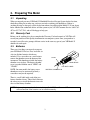
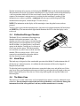
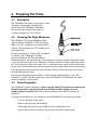
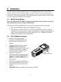
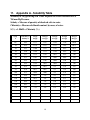
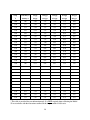
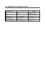
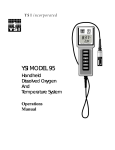
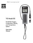
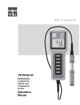
YSI Model 55
Handheld Dissolved
Oxygen and
Temperature
System
Operations
Manual
Table of Contents
1. General Description ......................................................................................................1
2. Specifications ................................................................................................................2
3. Preparing The Meter .....................................................................................................3
3.1. Unpacking.........................................................................................................................3
3.2. Warranty Card ..................................................................................................................3
3.3. Batteries ............................................................................................................................3
3.4. Calibration/Storage Chamber...........................................................................................4
3.5. Hand Strap ........................................................................................................................4
3.6. The Meter Case.................................................................................................................4
4. Preparing The Probe.....................................................................................................5
4.1. Description........................................................................................................................5
4.2. Choosing The Right Membrane.......................................................................................5
4.3. Probe Preparation..............................................................................................................5
4.4. Membrane Installation......................................................................................................6
4.5. Probe Operation and Precautions.....................................................................................7
5. Calibration......................................................................................................................8
5.1. Before You Calibrate........................................................................................................8
5.2. The Calibration Process....................................................................................................8
6. Principles Of Operation................................................................................................10
6.1. Discussion Of Measurement Errors.................................................................................10
7. Troubleshooting............................................................................................................12
8. Warranty And Repair ....................................................................................................14
8.1. Cleaning Instructions........................................................................................................15
8.2. Packing Instructions .........................................................................................................16
9. Required Notice.............................................................................................................17
10. Accessories And Replacement Parts .......................................................................18
11. Appendix A - Solubility Table ....................................................................................19
12. Appendix B - Conversion Chart ................................................................................21
i
1. General Description
The YSI Model 55 Handheld Dissolved Oxygen System is a rugged, micro-processor based, digital
meter with an attached YSI dissolved oxygen probe.
The YSI Model 55 is designed for field use and is available with cable lengths of 12, 25 or 50 feet.
The body of the probe has been manufactured with stainless steel to add rugged durability and
sinking weight. The large Liquid Crystal Display (LCD) is easy to read and is equipped with a backlight for use in dark or poorly lighted areas.
The Model 55's micro-processor allows the system to be easily calibrated with the press of a few
keys. Additionally, the micro-processor performs a self-diagnostic routine each time the instrument
is turned on. The self-diagnostic routine provides you with useful information about the function of
the instrument circuitry and the quality of the readings you obtain. For a list of these diagnostic
features, see chapter 7 Troubleshooting.
The system simultaneously displays temperature in oC and dissolved oxygen in either mg/L
(milligrams per liter) or % air saturation. The system requires only a single calibration regardless of
which dissolved oxygen display you use. You can switch back and forth from % air saturation to
mg/L with a single push of the MODE key.
A calibration chamber is built into the instrument. A small sponge in the chamber can be moistened
to provide a water saturated air environment which is ideal for air calibration. This chamber is also
designed for transporting and storing the probe. When the probe is stored in the chamber, the moist
environment will prolong effective membrane performance and probe life.
The instrument is powered by six AA-size alkaline batteries. A new set of alkaline batteries will
provide approximately 100 hours of continuous operation. When batteries need to be replaced, the
LCD will display a "LO BAT" message.
The YSI Model 55 instrument case is splash resistant. You can operate your Model 55 in a steady
rain without damage to the instrument.
1
2. Specifications
Probe Operating Environment
Medium: fresh, sea, or polluted water
Temperature: -5 to +45oC
Depth: 0 to 12, 0 to 25 or 0 to 50 feet (depending on cable length)
Meter Ambient Operating/Storage Temperature: -10 to +50oC
Material: ABS, Stainless Steel, Acrylic, and other materials.
Dimensions:
Height: 9.5 inches
(24.13 cm)
Thickness:
2.2 inches
(5.6 cm)
Width:
3.5 inches max.
( 8.89 cm)
Weight:
1.7 pounds
( 0.77 kg)
Power: 9 VDC - 6 AA-size Alkaline Batteries (included)
Approximately 100 hours operation from each new set of batteries
Water Tightness: Meets or exceeds IP65 standards
Extensive testing of the YSI Model 55 suggests the following typical performance:
Temperature
Sensor Type................Thermistor
Range..........................-5 to +45oC
Accuracy ....................± 0.2oC
Resolution ..................0.1oC
Dissolved Oxygen % Saturation
Sensor Type................Membrane covered polarographic
Range..........................0 to 200 % air saturation
Accuracy ....................± 2 % air saturation
Resolution ..................0.1 % air saturation
Dissolved Oxygen mg/L
Sensor Type................Calculated from % air saturation, temperature and salinity.
Range..........................0 to 20 mg/L
Accuracy ....................± 0.3 mg/L
Resolution ..................0.01 mg/L
2
3. Preparing The Meter
3.1. Unpacking
When you unpack your new YSI Model 55 Handheld Dissolved Oxygen System for the first time,
check the packing list to make sure you have received everything you should have. If there is
anything missing or damaged, call the dealer from whom you purchased the Model 55. If you do not
know which of our authorized dealers sold the system to you, call YSI Customer Service at 800-7654974 or 937-767-7241, and we'll be happy to help you.
3.2. Warranty Card
Before you do anything else, please complete the Warranty Card and return it to YSI. This will
record your purchase of this quality instrument in our computer system. Once your purchase is
recorded, you will receive prompt, efficient service in the event any part of your YSI Model 55
should ever need repair.
3.3. Batteries
There are a few things you must do to prepare
your YSI Model 55 for use. First, locate the six
AA-size alkaline batteries which were
included. Use a screwdriver or a small coin to
remove the thumbscrew on the bottom of the
instrument. This thumbscrew holds the batterychamber cover in place. The battery-chamber
cover is marked with the words "OPEN" and
"CLOSE."
O-RING
HAND STRAP
POLARITY LABEL
NOTE: On some models, the battery cover
thumbscrew may be unscrewed by hand (a
screwdriver may not be required).
BATTERY CHAMBER LID
There is a small label inside each of the two
battery-chamber sleeves. These labels illustrate
the correct way to install the batteries into each
sleeve of the battery-chamber.
NOTE: It is very important that the batteries be installed ONLY as illustrated. The instrument
will not function if the batteries are installed incorrectly.
3
Turn the instrument on by pressing and releasing the ON/OFF button on the front of the instrument.
The instrument will activate all segments of the display for a few seconds, which will be followed by
a self test procedure which will last for several more seconds. During this power on self test
sequence, the instrument’s microprocessor is verifying that the instrument is working. If the
instrument were to detect a problem, a continuous error message would be displayed. If the
instrument does not operate, consult chapter 7 Troubleshooting.
NOTE: The information on the display will be meaningless since the probe has not yet been
prepared.
You may also want to take the instrument into a dark room and, with the instrument ON, hold down
the LIGHT key. The instrument back-light should illuminate the LCD so that the display can be
easily read.
3.4. Calibration/Storage Chamber
The Model 55 has a convenient calibration/storage
chamber built into the instrument’s side. This
chamber provides an ideal storage area for the probe
during transport and extended non-use. If you look
into the chamber, you should notice a small round
sponge in the bottom. Carefully put 3 to 6 drops of
clean water into the sponge. Turn the instrument
over and allow any excess water to drain out of the
chamber. The wet sponge creates a 100% water
saturated air environment for the probe which is
ideal for dissolved oxygen calibration.
CALIBRATION CHAMBER
3.5. Hand Strap
The hand strap is designed to allow comfortable operation of the Model 55 with minimum effort. If
the hand strap is adjusted correctly, it is unlikely that the instrument will be easily dropped or
bumped from your hand.
To adjust the hand strap on the back of the meter, unsnap the leather cover and pull the two Velcro
strips apart. Place your hand between the meter and the strap and adjust the strap length so that your
hand is snugly held in place. Press the two Velcro strips back together and snap the leather cover
back into place.
3.6. The Meter Case
The meter case is sealed at the factory and is not intended to be opened, except by authorized service
technicians. Do not attempt to separate the two halves of the meter case as this may damage the
instrument, break the water-proof seal, and may void the manufacturer's warranty.
4
4. Preparing The Probe
4.1. Description
The YSI Model 55 dissolved oxygen probe is a nondetachable, polarographic sensor designed
specifically for the YSI Model 55 Handheld
Dissolved Oxygen System. Probe cables are
available in lengths of 12, 25 or 50 feet.
4.2. Choosing The Right Membrane
The YSI Model 5775 Standard Membrane Kit is
supplied with the YSI Model 55. This kit contains
thirty 1 mil (.001") membranes and a bottle of KCl
solution. YSI recommends the 5775 membranes for
most applications.
For special conditions, a 0.5 mil (.0005") membrane
is available. Order YSI Model 5776 High
Sensitivity Membrane Kit. This half-thickness
membrane improves measurement time at low temperatures and helps suppress background current
at very low dissolved oxygen levels. When data is routinely collected at sample temperatures below
15oC and at dissolved oxygen levels below 20% air saturation, the low signal current resulting from
the use of the standard membranes tends to magnify the probe's inherent constant background signal.
Using the high sensitivity membranes in this situation will decrease the percentage of error due to
the probe's background current.
For long-term monitoring situations ONLY, a half-sensitivity, double-thickness, 2 mil (.002")
membrane is available. For these applications, order the YSI Model 5685 Membrane Kit, which
includes membranes and electrolyte.
4.3. Probe Preparation
The YSI Model 55 probe is shipped dry. Before using the Model 55, the protective membrane on
the probe tip must be removed, the probe must be filled with KCl solution and a new
membrane must be installed. Follow the instructions below to install the KCl solution and
membrane.
To prepare for installation of a new membrane on your YSI Model 55 dissolved oxygen probe:
1. Unscrew the probe sensor guard.
2. Remove the old O-ring and membrane.
3. Thoroughly rinse the sensor tip and KCl reservoir with distilled water.
4. Prepare the electrolyte according to the directions on the KCl solution bottle.
5
4.4. Membrane Installation
A. Secure a membrane between your thumb and the
probe body. Add electrolyte to the probe until a
large meniscus completely covers the gold
cathode.
NOTE: Handle the membrane material with care,
touching it at the ends only.
A
B
B. With the thumb and forefinger of your other hand,
grasp the free end of the membrane.
C. With a continuous motion, stretch the membrane
up, over, and down the other side of the sensor.
Stretching forms the membrane to the contour of
the sensor tip.
D. Secure the end of the membrane under your
forefinger while continuing to hold the probe.
C
E. Roll the O-ring over the end of the probe, being
careful not to touch the membrane surface. There
should be no wrinkles in the membrane or trapped
air bubbles under the membrane. Some wrinkles
may be removed by lightly tugging on the edges
of the membrane beyond the O-ring.
F. Trim off excess membrane with scissors or a
sharp knife. Check that the stainless steel
temperature sensor is not covered by excess
membrane.
D
E
G. Shake off excess KCl. Rinse the stainless steel
thoroughly with distilled water to prevent
corrosion. Reinstall the sensor guard. The sensor
should be kept in a humid environment (such as
the calibration chamber) between measurements
and when not in use.
6
F
4.5. Probe Operation and Precautions
1.
Membrane life depends on usage. Membranes will last a long time if installed properly and
treated with care. Erratic readings are a result of loose, wrinkled, damaged, or fouled
membranes, or from large (more than 1/8" diameter) bubbles in the electrolyte reservoir. If
erratic readings or evidence of membrane damage occurs, you should replace the membrane
and the KCl solution. The average replacement interval is two to four weeks.
2.
If the membrane is coated with oxygen consuming (e.g. bacteria) or oxygen evolving organisms
(e.g. algae), erroneous readings may occur.
3.
Chlorine, sulfur dioxide, nitric oxide, and nitrous oxide can affect readings by behaving like
oxygen at the probe. If you suspect erroneous readings, it may be necessary to determine if
these gases are the cause.
4.
Avoid any environment which contains substances that may attack the probe materials. Some of
these substances are concentrated acids, caustics, and strong solvents. The probe materials that
come in contact with the sample include FEP Teflon, acrylic plastic, EPR rubber, stainless steel,
epoxy, polyetherimide and the polyurethane cable covering.
5.
For correct probe operation, the gold cathode must always be bright. If it is tarnished (which
can result from contact with certain gases), or plated with silver (which can result from
extended use with a loose or wrinkled membrane), the gold surface must be restored. To restore
the cathode, you may either return the instrument to the factory or clean it using the YSI Model
5680 Probe Reconditioning Kit. Never use chemicals or abrasives not supplied with this kit.
6.
It is also possible for the silver anode to become contaminated, which will prevent successful
calibration. To clean the anode, remove the O-ring and membrane and soak the probe overnight
in 3% ammonium hydroxide. Next, rinse the sensor tip and KCl reservoir with deionized water,
add new KCl solution, and install a new membrane and O-ring. Turn the instrument on and
allow the system to stabilize for at least 30 minutes. If, after several hours, you are still unable
to calibrate, return the YSI Model 55 system to an authorized service center for service.
7.
If the sensor O-ring is worn or loose, replace it with the appropriate O-ring provided in the YSI
Model 5945 O-ring Pack.
8.
To keep the electrolyte from drying out, store the probe in the calibration/storage chamber with
the wet sponge.
7
5. Calibration
Dissolved oxygen calibration must be done in an environment with a known oxygen content.
Since the amount of oxygen in the atmosphere is known, it makes an excellent environment for
calibration (at 100% relative humidity). The calibration/storage chamber contains a moist sponge
to create a 100% water saturated air environment.
5.1. Before You Calibrate
Before you calibrate the YSI Model 55, complete the procedures discussed in the Preparing the
Meter and Preparing the Probe chapters of this manual.
To accurately calibrate the YSI Model 55, you will need to know the following information:
•
The approximate altitude of the region in which you are located.
•
The approximate salinity of the water you will be analyzing. Fresh water has a salinity of
approximately zero. Sea water has a salinity of approximately 35 parts per thousand (ppt). If
you are not certain what the salinity of the sample water is, use a YSI Model 30 SalinityConductivity-Temperature meter to determine it.
5.2. The Calibration Process
1.
Ensure that the sponge inside the
instrument's calibration chamber is wet.
Insert the probe into the calibration
chamber.
2.
Turn the instrument on by pressing the
ON/OFF button on the front of the
instrument. Wait for the dissolved oxygen
and temperature readings to stabilize
(usually 15 minutes is required after
turning the instrument on).
3.
To enter the calibration menu, use two
fingers to press and release both the UP
ARROW and DOWN ARROW keys at
the same time.
4.
The LCD will prompt you to enter the
local altitude in hundreds of feet. Use the
arrow keys to increase or decrease the
altitude.
CALIBRATION CHAMBER
EXAMPLE: Entering the number 12 here indicates 1200 feet.
8
5.
When the proper altitude appears on the LCD, press the ENTER key. The Model 55 should
now display CAL in the lower left of the display, the calibration value should be displayed in
the lower right of the display and the current DO reading (before calibration) should be on the
main display.
6.
Make sure that the DO reading (large display) is stable, then press the ENTER button. The
LCD will prompt you to enter the approximate salinity of the water you are about to analyze.
You can enter any number from 0 to 40 parts per thousand (PPT) of salinity. Use the arrow keys
to increase or decrease the salinity setting. When the correct salinity appears on the LCD (zero
for fresh water), press the ENTER key. The instrument will return to normal operation.
Once the calibration process is complete, the only keys which will remain operational are the
MODE key, the LIGHT key and the ON/OFF key. You can move back and forth from reading
dissolved oxygen in the mg/L mode or the % air saturation mode by pressing the MODE key. If you
are working in a dark area and have difficulty reading the LCD, press and hold the LIGHT key to
activate the back-light of the YSI Model 55. The ON/OFF key turns the instrument on or off.
For best results:
•
Each time the Model 55 is turned off, re-calibrate before taking measurements.
•
Calibrate at a temperature within ±10°C of the sample temperature.
9
6. Principles Of Operation
The sensor consists of an acrylic body with a circular gold cathode embedded in the end. Inside the
gold ring there is a small chamber containing a porous silver anode. In operation, this chamber is
filled with a solution of KCl electrolyte containing a small amount of surfactant to improve wetting
action.
A thin permeable membrane, stretched over the sensor, isolates the electrodes from the environment,
while allowing gases to enter. When a polarizing voltage is applied to the sensor electrodes, oxygen
which has passed through the membrane reacts at the cathode causing a current to flow.
The membrane passes oxygen at a rate proportional to the pressure difference across it. Since
oxygen is rapidly consumed at the cathode, it can be assumed that the oxygen pressure inside the
membrane is zero. Hence, the force causing the oxygen to diffuse through the membrane is
proportional to the partial pressure of oxygen outside the membrane. As the oxygen partial pressure
varies, so does the oxygen diffusion through the membrane. This causes the probe current to change
proportionally.
It is important to recognize that oxygen dissolved in the sample is consumed during the test. It is
therefore essential that the sample be continuously stirred at the sensor tip. If stagnation occurs, your
readings will be artificially low. Stirring may be accomplished by mechanically moving the sample
around the probe tip, or by rapidly moving the probe through the sample. The rate of stirring should
be at least 1 foot per second.
6.1. Discussion Of Measurement Errors
There are three basic types of dissolved oxygen errors. Type 1 errors are related to limitations of
instrument design and tolerances of instrument components. These are primarily the meter linearity
and the resistor tolerances. Type 2 errors are due to basic probe accuracy tolerances, mainly
background signal, probe linearity, and variations in membrane temperature coefficient. Type 3
errors are related to the operator's ability to determine the conditions at the time of calibration. If
calibration is performed against more accurately known conditions, type 3 errors are appropriately
reduced.
Type 1 Errors
A. Meter linearity error: ±1% of full scale reading, or ±0.15 mg/L
B. Component and circuitry error: ±0.05 mg/L
Type 2 Errors
A. DO errors caused by temperature compensation for measurements at ±10°C from calibration
temperature: ±1% (0.08 mg/L at 25°C)
DO errors caused by temperature measurement errors: A maximum ±0.2°C temperature error is
equal to ±0.5% (0.04mg/L at 25°C).
10
Type 3 Errors
A. Altitude:
Operator Error:
A 1000 foot error in altitude (when calibrating) is equal to an error of
approximately 3.6% at the 10 mg/L level.
Instrument Error: The maximum DO error caused by calibrating to altitude in increments
of 100 feet: ±0.18% (< 0.015 mg/L at 25°C)
B. Humidity:
Errors occur if calibration is performed at less than 100% humidity. The worst possible case
would be calibration at 0% humidity. The error varies with the calibration temperature as
follows:
Temperature
Calibration Error at 0% humidity
0oC
0.09 mg/L
10oC
0.14 mg/L
20oC
0.21 mg/L
30oC
0.33 mg/L
40oC
0.50 mg/L
Approximating The Error
It is unlikely that the actual error in any measurement will be the maximum possible error. A better
error approximation is obtained using a root mean squared (r.m.s.) calculation:
r.m.s. error = ±[1a2 + 1b2 + 2a2 + 2b2 + 3a2 + 3b2]½ mg/L
NOTE: This sample calculation is for a near extreme set of conditions.
11
7. Troubleshooting
NOTE: An error displayed briefly during the first few seconds after turning the
instrument on does NOT indicate a problem.
SYMPTOM
1. Instrument will not turn on
2. Instrument will not calibrate
3. Instrument "locks up"
POSSIBLE CAUSE
ACTION
A. Low battery voltage
A. Replace batteries (Page 3)
B. Batteries installed incorrectly
B. Check battery polarity. (Page 3)
C. Meter requires service
C. Return system for service (Page 14)
A. Membrane is fouled or damaged
A. Replace membrane and KCl (Page 6)
B. Probe anode is fouled or dark
B. Clean anode (Page 7)
C. Probe cathode is tarnished
C. Clean cathode (Page 7)
D. System requires service
D. Return system for service (Page 14)
A. Instrument has received a shock
B. Batteries are low or damaged
A. Remove battery lid, wait 15 seconds
for reset, replace lid. (Page 3)
C. System requires service
B. Replace batteries (Page 3)
C. Return system for service (Page 14)
4. Instrument readings are inaccurate
A. Cal altitude is incorrect
A. Recalibrate w/correct value (Page 8)
B. Salinity setting is incorrect
B. Recalibrate w/correct value (Page 8)
C. Probe not in 100% water saturated
air during Cal procedure
D. Membrane fouled or damaged
C. Moisten sponge and place in Cal
chamber w/ probe and Recal (Page 4,
8)
E. Probe anode is fouled or dark
D. Replace membrane (Page 6)
F. Probe cathode is tarnished
E. Clean anode (Page 7)
G. System requires service
F. Clean cathode (Page 7)
G. Return system for service (Page 14)
5. LCD displays "LO BAT"
A. Batteries are low or damaged
A. Replace batteries (Page 3)
A. Probe current too low to calibrate
A. Replace membrane and KCl (Page 6)
or
Main display flashes “OFF”
6. Main display reads “undr”
B. System requires service
B. Clean anode (Page 7)
C. Clean cathode (Page 7)
D. Return system for service (Page 14)
7. Main display reads “OVEr”
A. Sample O2 concentration is more
than 20 mg/L
A. Recalibrate using correct altitude and
salinity compensation (Page 8).
B. Probe current too high to calibrate
B. Replace membrane and KCl (Page 6)
C. System requires service
C. Clean cathode (Page 7)
D. Clean anode (Page 7)
E. Return system for service (Page 14)
8. Main display reads "Er 0"
A. Calibration current out of range
A. Replace membrane and KCl (Page 6)
B. Instrument's self-test detects
improper probe voltage during
calibration
B. Clean anode (Page 7)
12
C. Clean cathode (Page 7)
D. Return system for service (Page 14)
SYMPTOM
9. Main display reads "Er 1"
or
Main display reads “Err”
(Secondary display reads “ra”)
10. Main display reads "Er 2"
or
Main display reads “Err”
POSSIBLE CAUSE
ACTION
A. Instrument's self-test detects a
variance in RAM
A. Remove battery lid, wait 15 seconds
for reset, replace lid. (Page 3)
B. System requires service
B. Return system for service (Page 14)
A. Instrument's self-test detects a
variance in ROM checksum
A. Remove battery lid, wait 15 seconds
for reset, replace lid. (Page 3)
B. System requires service
B. Return system for service (Page 14)
A. Instrument's self-test detects a
system malfunction or component
failure
A. Remove battery lid, wait 15 seconds
for reset, replace lid. (Page 3)
(Secondary display reads “ro”)
11. Main display reads "Er 3"
or
Main display reads "FAIL"
(secondary display reads “eep”)
12. Main display reads "Er 4"
B. Return system for service (Page 14)
B. System requires service
A. Sample O2 concentration is more
than 20 mg/L
A. Recalibrate using correct altitude and
salinity compensation (Page 8).
B. System requires service
B. Replace membrane and KCl (Page 6)
C. Clean anode (Page 7)
D. Clean cathode (Page 7)
E. Return system for service (Page 14)
13. Main display reads "Er 5"
14. Main display reads "Er 6"
A. Displayed O2 concentration is below
-0.5 mg/L.
A. Recalibrate using correct altitude and
salinity compensation (Page 8).
B. System requires service
B. Return system for service (Page 14)
A. Sample O2 concentration is over
range (% mode)
A. Recalibrate using correct altitude and
salinity compensation (Page 8).
B. System requires service
B. Replace membrane and KCl (Page 6)
C. Clean anode (Page 7)
D. Clean cathode (Page 7)
E. Return system for service (Page 14)
15. Main display reads "Er 7"
16. Secondary display reads "Er 8"
or
Main Display reads “OVEr”
A. Displayed O2 concentration is below
-3.0%
A. Recalibrate using correct altitude and
salinity compensation (Page 8).
B. System requires service
B. Return system for service (Page 14)
A. Sample temperature is more than
+45.9oC
A. Reduce the sample temperature
B. Return system for service (Page 14)
B. System requires service
(Secondary display reads “ovr”)
17. Secondary display reads "Er 9"
or
Main Display reads “OVEr”
A. Sample temperature is less than
o
-5 C
A. Increase sample temperature.
B. Return system for service (Page 14)
B. System requires service
(Secondary display reads “udr”)
18. Main display reads "Er A"
A. Short in probe/cable assembly
A. Replace probe/cable assembly
B. System requires service
B. Return system for service (Page 14)
13
8. Warranty And Repair
YSI Model 55 Dissolved Oxygen and Temperature Meters are warranted for two years from date of
purchase by the end user against defects in materials and workmanship. YSI Model 55 probes and cables
are warranted for one year from date of purchase by the end user against defects in material and
workmanship. Within the warranty period, YSI will repair or replace, at its sole discretion, free of charge,
any product that YSI determines to be covered by this warranty.
To exercise this warranty, write or call your local YSI representative, or contact YSI Customer Service in
Yellow Springs, Ohio. Send the product and proof of purchase, transportation prepaid, to the Authorized
Service Center selected by YSI. Repair or replacement will be made and the product returned,
transportation prepaid. Repaired or replaced products are warranted for the balance of the original
warranty period, or at least 90 days from date of repair or replacement.
Limitation of Warranty
This Warranty does not apply to any YSI product damage or failure caused by (i) failure to install,
operate or use the product in accordance with YSI’s written instructions, (ii) abuse or misuse of the
product, (iii) failure to maintain the product in accordance with YSI’s written instructions or standard
industry procedure, (iv) any improper repairs to the product, (v) use by you of defective or improper
components or parts in servicing or repairing the product, or (vi) modification of the product in any way
not expressly authorized by YSI.
THIS WARRANTY IS IN LIEU OF ALL OTHER WARRANTIES, EXPRESSED OR IMPLIED, INCLUDING ANY
WARRANTY OF MERCHANTABILITY OR FITNESS FOR A PARTICULAR PURPOSE. YSI’s LIABILITY
UNDER THIS WARRANTY IS LIMITED TO REPAIR OR REPLACEMENT OF THE PRODUCT, AND THIS
SHALL BE YOUR SOLE AND EXCLUSIVE REMEDY FOR ANY DEFECTIVE PRODUCT COVERED BY THIS
WARRANTY. IN NO EVENT SHALL YSI BE LIABLE FOR ANY SPECIAL, INDIRECT, INCIDENTAL OR
CONSEQUENTIAL DAMAGES RESULTING FROM ANY DEFECTIVE PRODUCT COVERED BY THIS
WARRANTY.
YSI Authorized Service Centers
Please visit www.ysi.com or contact YSI Technical Support for the nearest authorized service center.
YSI Incorporated • Technical Support • Phone: +1 937 767-7241 • 800 897-4151 • Fax: 937 767-1058 • Email: [email protected]
14
8.1. Cleaning Instructions
NOTE: Before they can be serviced, equipment exposed to biological, radioactive, or toxic
materials must be cleaned and disinfected. Biological contamination is presumed for any
instrument, probe, or other device that has been used with body fluids or tissues, or with waste
water. Radioactive contamination is presumed for any instrument, probe or other device that has
been used near any radioactive source.
If an instrument, probe, or other part is returned or presented for service without a Cleaning
Certificate, and if in our opinion it represents a potential biological or radioactive hazard, our
service personnel reserve the right to withhold service until appropriate cleaning,
decontamination, and certification has been completed. We will contact the sender for
instructions as to the disposition of the equipment. Disposition costs will be the responsibility of
the sender.
When service is required, either at the user's facility or at YSI, the following steps must be taken
to insure the safety of our service personnel.
1. In a manner appropriate to each device, decontaminate all exposed surfaces, including any
containers. 70% isopropyl alcohol or a solution of 1/4 cup bleach to 1 gallon tap water are
suitable for most disinfecting. Instruments used with waste water may be disinfected with
.5% Lysol if this is more convenient to the user.
2. The user shall take normal precautions to prevent radioactive contamination and must use
appropriate decontamination procedures should exposure occur.
3. If exposure has occurred, the customer must certify that decontamination has been
accomplished and that no radioactivity is detectable by survey equipment.
4. Any product being returned to the YSI Repair Center, should be packed securely to prevent
damage.
5. Cleaning must be completed and certified on any product before returning it to YSI.
15
8.2. Packing Instructions
1. Clean and decontaminate items to insure the safety of the handler.
2. Complete and include the Cleaning Certificate.
3. Place the product in a plastic bag to keep out dirt and packing material.
4. Use a large carton, preferably the original, and surround the product completely with packing
material.
5. Insure for the replacement value of the product.
Cleaning Certificate
Organization
Department
Address
City
State
Zip
Country
Phone
Model No. of Device
Lot Number
Contaminant (if known)
Cleaning Agent(s) used
Radioactive Decontamination Certified?
(Answer only if there has been radioactive exposure)
Yes
No
Cleaning Certified By
Name
Date
16
9. Required Notice
The Federal Communications Commission defines this product as a computing device and requires
the following notice:
This equipment generates and uses radio frequency energy and if not installed and used properly,
may cause interference to radio and television reception. There is no guarantee that interference will
not occur in a particular installation. If this equipment does cause interference to radio or television
reception, which can be determined by turning the equipment off and on, the user is encouraged to
try to correct the interference by one or more of the following measures:
•
•
•
•
re-orient the receiving antenna
relocate the computer with respect to the receiver
move the computer away from the receiver
plug the computer into a different outlet so that the computer and receiver are on
different branch circuits.
If necessary, the user should consult the dealer or an experienced radio/television technician for
additional suggestions. The user may find the following booklet, prepared by the Federal
Communications Commission, helpful: "How to Identify and Resolve Radio-TV Interference
Problems." This booklet is available from the U.S. Government Printing Office, Washington, DC
20402, Stock No. 0004-000-00345-4.
17
10. Accessories And Replacement Parts
The following parts and accessories are available from YSI or any Franchise Dealer authorized by
YSI.
YSI Order Number
Description
5775
Standard Membrane and KCl kit (1 mil)
5776
High Sensitivity Membrane and KCl kit (.5 mil)
5685
Half Sensitivity Membrane Kit (2 mil)
5680
Probe Reconditioning Kit (sanding tool and disks for cathode cleaning)
5945
O-ring Kit
5520
Carrying Case
055205
Replacement Probe and Cable Assembly (12 feet)
055206
Replacement Probe and Cable Assembly (25 feet)
055229
Replacement Probe and Cable Assembly (50 feet)
055201
Replacement Front Case Cover
055242
Replacement Rear Case Cover
055244
Replacement Battery Cover Kit
055204
Replacement Case Gasket and Screw
055219
Storage Chamber Sponge
115603
Main Board Assembly
18
11. Appendix A - Solubility Table
Solubility of Oxygen in mg/L in Water Exposed to Water-Saturated Air at
760 mm Hg Pressure.
Salinity = Measure of quantity of dissolved salts in water.
Chlorinity = Measure of chloride content, by mass, of water.
0
0
S( /00) = 1.80655 x Chlorinity ( /00)
Chlorinity: 0
5.0 ppt
10.0 ppt
15.0 ppt
20.0 ppt
25.0 ppt
C
Salinity: 0
9.0 ppt
18.1 ppt
27.1 ppt
36.1 ppt
45.2 ppt
0.0
14.62
13.73
12.89
12.10
11.36
10.66
1.0
14.22
13.36
12.55
11.78
11.07
10.39
2.0
13.83
13.00
12.22
11.48
10.79
10.14
3.0
13.46
12.66
11.91
11.20
10.53
9.90
4.0
13.11
12.34
11.61
10.92
10.27
9.66
5.0
12.77
12.02
11.32
10.66
10.03
9.44
6.0
12.45
11.73
11.05
10.40
9.80
9.23
7.0
12.14
11.44
10.78
10.16
9.58
9.02
8.0
11.84
11.17
10.53
9.93
9.36
8.83
9.0
11.56
10.91
10.29
9.71
9.16
8.64
10.0
11.29
10.66
10.06
9.49
8.96
8.45
11.0
11.03
10.42
9.84
9.29
8.77
8.28
12.0
10.78
10.18
9.62
9.09
8.59
8.11
13.0
10.54
9.96
9.42
8.90
8.41
7.95
14.0
10.31
9.75
9.22
8.72
8.24
7.79
15.0
10.08
9.54
9.03
8.54
8.08
7.64
16.0
9.87
9.34
8.84
8.37
7.92
7.50
17.0
9.67
9.15
8.67
8.21
7.77
7.36
18.0
9.47
8.97
8.50
8.05
7.62
7.22
19.0
9.28
8.79
8.33
7.90
7.48
7.09
Temp
o
19
Chlorinity: 0
5.0 ppt
10.0 ppt
15.0 ppt
20.0 ppt
25.0 ppt
C
Salinity: 0
9.0 ppt
18.1 ppt
27.1 ppt
36.1 ppt
45.2 ppt
20.0
9.09
8.62
8.17
7.75
7.35
6.96
21.0
8.92
8.46
8.02
7.61
7.21
6.84
22.0
8.74
8.30
7.87
7.47
7.09
6.72
23.0
8.58
8.14
7.73
7.34
6.96
6.61
24.0
8.42
7.99
7.59
7.21
6.84
6.50
25.0
8.26
7.85
7.46
7.08
6.72
6.39
26.0
8.11
7.71
7.33
6.96
6.62
6.28
27.0
7.97
7.58
7.20
6.85
6.51
6.18
28.0
7.83
7.44
7.08
6.73
6.40
6.09
29.0
7.69
7.32
6.96
6.62
6.30
5.99
30.0
7.56
7.19
6.85
6.51
6.20
5.90
31.0
7.43
7.07
6.73
6.41
6.10
5.81
32.0
7.31
6.96
6.62
6.31
6.01
5.72
33.0
7.18
6.84
6.52
6.21
5.91
5.63
34.0
7.07
6.73
6.42
6.11
5.82
5.55
35.0
6.95
6.62
6.31
6.02
5.73
5.46
36.0
6.84
3.52
6.22
5.93
5.65
5.38
37.0
6.73
6.42
6.12
5.84
5.56
5.31
38.0
6.62
6.32
6.03
5.75
5.48
5.23
39.0
6.52
6.22
5.98
5.66
5.40
5.15
40.0
6.41
6.12
5.84
5.58
5.32
5.08
41.0
6.31
6.03
5.75
5.49
5.24
5.01
42.0
6.21
5.93
5.67
5.41
5.17
4.93
43.0
6.12
5.84
5.58
5.33
5.09
4.86
44.0
6.02
5.75
5.50
5.25
5.02
4.79
45.0
5.93
5.67
5.41
5.17
4.94
4.72
Temp
o
* This table is provided for your information only. It is NOT required when calibrating the Model
55 in accordance with the instructions outlined in the chapter entitled Calibration.
20
12. Appendix B - Conversion Chart
To Convert From
To
Equation
Feet
Meters
Multiply by 0.3048
Meters
Feet
Multiply by 3.2808399
Degrees Celsius
Degrees Fahrenheit
(°C × 9/5) + 32
Degrees Fahrenheit
Degrees Celsius
(°F - 32) × 5/9
Milligrams per liter (mg/L)
Parts per million (ppm)
Multiply by 1
21
1725 Brannum Lane
Yellow Springs, Ohio 45387 USA
937 767-7241 • 800 765-4974 • Fax 937 767-9353
[email protected] • www.YSI.com
© 1997 YSI Incorporated
055207
A55207D - Web
January 07