1
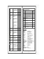
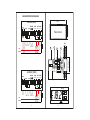
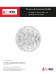
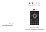
COLD ROOM CONTROLLER
USER MANUAL
INDIA
www.subzero.co
SZ-7524-P
Operation
When operating in the field of refrigeration, temperature control is
performed with a positive differential. The compressor stops when
the Setpoint temperature is reached and restarts when the
temperature reaches Setpoint plus the differential.
SZ-7524-P
Introduction.
Features :
2 NTC probes for cold room temp. + Evap. coil temperature.
Range : -40.00C to 50.00C.
Relay outputs : Compressor + Defrost + Evap. Fan.
Compressor protection algoriithm.
Auto/Man defrosting facility (Time/Temp based).
Buzzer Output
Sr
Parameter setting method
Min
1
Two different defrost types can be selected : electrical the
compressor is stopped or at cycle inversion (Warm gas, the
compressor keeps working). It is also possible to select the interval
between defrosts (and the interval count type) and a maximum time
(time-out) after which defrost is interrupted. The same probe which
controls the defrost cycle is used to control the evaporator fans. It is
possible to set the temperature, the delay time after a defrost and
relation of fans with the compressor.
Set point
Function : To set the cutout
point of the controller.
Press and hold
SET key for
2 second and
release.
Display will change to set value
and LED will flash. The set point
value can now be changed by
using the UP/DOWN key. After
setting the desired value. Press
the SET key and you will see
“- - -” which confirms that the
set point has been stored in
memory.
Press & Hold
DOWN(prg)
key
for 2 seconds.
Display will show P2 & will
flash. To go to other parameters,
use UP/DOWN keys.
2
P2 parameter
Function: To set maximum
allowable high temperature limit.
P2
To change the
P2 parameter,
press the
SET key.
Use UP/DOWN keys to set
desired value. Once set at a
particular value, this will not allow
the set point to go above this
value and below P3 setting.
XX = Set point
Example : Setting this parameter
at 25.0 0C will not allow the set
0
point to go above 25.0 C. Also,
H
(Message on Display) if the temperature reaches
25.00C, the display will show Ht
1
P3
value
Max Fac
Set
P2
0.00C
To set other
parameter
A series of “safety controls” (delay at start-up, minimum disable
time, minimum time between activation) protects the compressors
from close starts. In case of probe error or temperature alarm, the
instrument signals the event through acoustic signal and by closing
the relay contract. By pressing the mute key, the buzzer is silenced.
These functions can be easily customised by setting some
programming parameters. Other parameters allow to suit the
instrument to various applications.
Parameter
R
2
XX
50.00C 50.00C
P5
(High Temp) indicating that the
temperature has gone above the
value in this parameter and at
this point the buzzer will come on.
3
P3
P3 parameter
Function: To set minimum
-40.00C XX
allowable Low temperature limit.
To change
the P3
parameter,
press the
SET key
Use UP/DOWN keys to set
desired value. Once set at a will
particular value, this not allow
the set point to go below this
value and above P2 setting.
XX = Set point
L
(Message on Display)
4
P4
-40.00C
Function : To set the comp.
differential (hysterisis).
To change
the P4
parameter,
press the
SET key.
Use UP/DOWN keys to set
desired value. Differential
between cutout and cutin
temperature can be set
between 0.10C to 20.00C
6
0.10C 20.00C 2.00C
Example: If the set point is set
at 10.00C and differential is
set at 2.00C, then when the
system reaches 10.00C, the
comp. relay will cutout. Since
the differential is 2.00C, the comp.
Relay will cutin at 12.00C.
(10.00C + 2.00C)
5
P5 parameter
Function : To set probe 1
offset (cold room temp.)
calibration.
3
Use UP/DOWN keys to set
desired value. In time it may be
possible that the display may
be offset by a degree or so.
To compensate for this error,
you may need to add or minus
the degrees required to achieve
the correct temperature.
Setting value is from 10.00C to + 10.00C
Example: The temperature on
the display is 28.00C, whereas
the actual temperature is 30.00C.
You will need to set the P5 mode
to 2.00C, which means that once
out of the programming mode,
that once out of the programming
mode, the temperature will show
30.00C (28.00C + 2.00C).
Example: Setting this parameter
at -30.0 0C will not allow the set
point to go below -30.0 0C. Also,
if the temperature reaches
-30.0 0C, the display will show
Lt(Low Temp) indicating that the
temperature has gone below
the value in this parameter and
at this point the buzzer will
come on.
P4 parameter
To change
the P5
parameter,
press the
SET key
-10.00C 10.00C 0.00C
P6
P6 parameter
Function: To set time delay
between compressor relay
restart time.
To change
the P6
parameter,
press the
SET key.
Use UP/DOWN keys to set
desired value. This parameter is
used to protect the compressor
from restarting in a short period
of time and can be set between
0 to 20 minutes.
Example: If this parameter is
set at 3 minutes, the relay will
cut off at the set temperature, but
will cut off at the set temperature,
but will not restart for a minimum
of 3 minutes, even if the
differential is achieved earlier.
This parameter is good to protect
the life of the compressor or
even in applications where the
probe is placed at places where
there are sudden & short in
temperature like above a cold
room door.
4
0 Min 20 Min 3 Min
7
P7 parameter
Function: To set drip time for
defrost water to drain out.
To change
the P7
parameter,
press the
SET key.
Use UP/DOWN keys to get
desired value. This is the time
for which the fan, compressor,
heater will stay off so that the
defrost water can drip & drain out.
P8 parameter
Function: To set compressor
relay status on room probe
failure.
To change
the P8
parameter,
press the
SET key.
Use UP/DOWN keys to set
desired value.
When set to
0 = Comp status is ON.
1 = Comp performs a duty cycle
10 minutes ON and 4minutes
OFF.
2 = Comp status is OFF.
9
L1 parameter
Function: Evap. fan stop temp
(Coil)
L1
To change
the L1
parameter,
press the
SET key.
Use UP/DOWN keys to set
desired value. This setting
is used to limit the max
temperature beyond which the
Evap. fan will cut off.
10
L2 parameter
Function: To set time delay
between Evap. fan relay restart
time.
L2
To change
the L2
parameter,
press the
SET key.
Use UP/DOWN keys to set
desired value. If for example
this is set at 3 minutes, the Evap.
Fan relay will cutoff at the temp.
set by L1 parameter but the fan
will not come on for a minimum
of 3 minutes even if L4 is
achieved earlier.
P7
8
P8
11
L3 parameter
Function: Evap. Fan operation
when compressor is off.
L3
To change
the L3
parameter,
press the
Use UP/DOWN keys to set
desired value.
0 = Evap. Fan is off when comp.
is off
5
SET key.
0 Min 99 Min 1 Min
0
2
L4 parameter
L4
To change
the L4
parameter,
press the
SET key.
Use UP/DOWN keys to set
desired value.
Example: If L1 parameter is set
to 2.00C, and the L4 is set to
2.00C, then Evap. fan will cut off
at 2.00C and restart only at 0.00C
13
L5 parameter
0
0
0
Function: To set probe 2 offset -10.0 C 10.0 C 0.0 C
calibration (Evap. fan coil probe)
L5
To change
the L5
parameter,
press the
SET key.
Use UP/DOWN keys to set
desired value. In time it may
be possible that the temp. on
the display may be offset
by a degree or so. To
compensate for this error, you
may need to add or minus the
degrees required to achieve
the correct temperature. Setting
value is from -10.00C to + 10.00C
14
L6 parameter
Function: Evap. fan status
during defrost.
L6
To change
the L6
parameter,
press the
SET key.
Use UP/DOWN keys to set
desired value.
1 = Evap. fan will stay off during
defrost
0 = Evap. fan will stay on during
defrost.
15
E1 parameter
Function: To set type of defrost
E1
To change
the E1
parameter,
press the
SET key.
Use UP/DOWN keys to set
desired value.
0 = Heater defrost in which case
compressor is off.
1 = Hot gas defrost where
compressor is on.
16
E2 parameter
Function: To set type of
computation for defrost time.
0
0
-40.00C 50.0 C 2.0 C
0
1
0
0
0
Function: Evap. Fan differential 0.1 C 20.0 C 2.0 C
(hysterisis)
12
1
0 Min 20 Min 1 Min
1 = Evap. Fan will stay on when
compressor is off.
1
6
0
1
1
0
1
0
0
1
0
E2
To change
the E2
parameter,
press the
SET key.
Use UP/DOWN keys to set
desired value.
0 = Total of real time.
For example if the unit goes into
defrost at this moment, the
calculation of time will start at
that movement.
1 = Sum of total compressor
operating times. This means
that for time calculation, the
unit will add the total time the
compressor has been in an
ON mode.
7524 keeps a record of the
hours worked +/-1 hour incase
of a power failure.
Eg. If E3 is set to 6 hrs and
3.1/2 hrs have passed after unit
has started and power fails,
then defrost cycle will start after
3 hours when power resumes.
E8 parameter
Function: Defrost duration
during Coil probe failure
(Only manual)
E8
To change
the E8
parameter,
press the
SET key.
Use UP/DOWN keys to get
desired value and press SET
key .
Example: if this is set to 5 min,
then manual defrost for 5 min
will take place during Coil probe
fail.
21
AL parameter
Function: Power on time delay
for Alarm
AL
To change
the AL
parameter,
press the
SET key.
Use UP/DOWN keys to get
desired value and press SET
key .
Example : If you set this
parameter to 20, once the power
is switched on, the alarm will
not activate for 20 minutes after
the power is switched on. This
is most useful to avoid the
nuisance alarms when the
ambients are high when the
machine is switched on after a
long time.
Note : After pressing Mute key,
buzzer will come ON, after every
10 Mins. til that fault gets
cleared.
22
FS parameter
Revert to factory set parameter
FS
To change
theFS
parameter,
press the
SET key.
1 = Revert to factory set
parameter
Useful to debug setting related
problems.
23
LP parameter
Function: To lock keypad.
LP
To change
the LP
parameter,
press the
SET key.
Use UP/DOWN keys to set
desired value.
This parameter can lock the
keypad so that tampering is
not possible by by-standers.
1 actives keypad lock
1 Hr 31 Hrs 6 Hrs
17
E3 parameter
Function: To set Defrost
frequency.
E3
To change
the E3
parameter,
press the
SET key
Use UP/DOWN keys to set
desired value. This is the
amount of time between two
defrost cycles.
18
E4 parameter
Function: To set maximum
Defrost duration
E4
To change
the E4
parameter,
press the
SET key.
Use UP/DOWN keys to set
desired value.
This is the maximum amount of
time allowed for a defrost.
If set to 0, there will be no defrost
cycle.
19
E5 parameter
0
0
0
Defrost stop temperature (Evap. -40.0 C 50.0 C 8.0 C
coil probe)
E5
To change
the E5
parameter,
press the
SET key.
This is the maximum
temperature allowable at which
the defrost process will stop.
0 Min 99 Min 30 Min
Defrost will stop according to E4 & E5 parameter, whichever is achieved earlier.
7
20
8
1 Min 10 Min 5 Min
0Min 99Min 30Min
0
1
0
0
1
0
0 de-activates keypadlock.
on activation, all the parameters
can only be viewed. but not
modified.
24
rS
rS parameter
To change
the rS
parameter,
press the
SET key.
Function: To change the
resolution.
Use UP/DOWN keys to set
desired value.
This parameter when set to 0,it
will take all parameter in 0.10C
resolution.
This parameter when set to 1,it
will take all parameter in 10C
resolution.
Note : Temperature and
parameter will also change
accordingly.
25
EP parameter
Function: To end programming.
EP
To end
programming
press the
SET key.
Once the SET key is pressed,
the control goes into the normal
mode and displays the
temperature and all settings are
recorded.
UP Key
To view a coil temp.
UP key.
Down Key
Down & Program key.
Mute Key
This key will mute the buzzer.
Manual defrost
SZ-7524-P
Set Key
To force a Manual Defrost, press
this key for 4 seconds the unit
will go into defrost mode.
If E4 parameter is set to 0, or Coil
temp. is greater than defrost stop
temp. this key will remain
inactive.
Operating messages and Icon status
Message
0
1
Description
Parameter
Ht
Temperature above the maximum limit of the set point.
P2
Lt
Temperature below the minimum limit of the set point.
P3
PP
Probe short circuit, circuit open or without
probe, or temperature < -40.00C or > 50.00C
0
On/Off
Flashing
On
On/Off
Flashing
Flashing
Set Point, P4,
P6
Comp. Relay on/off
Alarm (Ht, Lt, PP)
Defrosting in progress
E3, E4, E5
Evap. fan Relay on/off
L1, L4
Comp. Relay in Timedelay
P6
Evap. Fan Relay in Timedelay
L2
Technical data :
Housing
Front Cover
Dimensions
: Black, ABS Plastic.
: Red Ploycarbonate plastic.
: Front - 75 x 34.5 MM,
Depth- 71MM(w/o. back lid).
Panel Cutout
: 29X71mm.
Mounting
: Flush panel mounting with fasteners.
Protection
: Front panel is waterproof &
I.P.65 rated.
Connection
: Screw terminal blocks.
2.5sq mm one wire/terminal only.
Display
: 3X14.2 MM (0.56”)LED.
Data Storage
: Non-Volatile EEPROM Memory.
Power Input (Options) : 230Vac +/-10%, 50-60Hz, Other on request.
Operating Temp
: 50 C to 500C(non-condensing).
Storage temp
: -200C to 700C(non-condensing).
Output
: 3 SPDT relay, 8(3)A, 250Vac.
Input
: 2 NTC Probe.
Range
: -40.00C to +50.00C.
Resolution
: 10C / 0.10C.
Accuracy
: +/-10C.
Probe Tolerance at 250C : +/-0.30C.
Alarm (Buzzer)
: SZ-B75. 10V,10mA.
Set key.
9
10
SUGGESTED WIRING DIAGRAM
71mm
SZ-7524-P (230V)
2
3
4
To
SZ-N75
5
To
SZ-N75
6
7
+
-
COMP.
FAN DEFROST
NC
NO
NO
C
NO
8
9
10
11
12
To
SZ-B75
(10Vdc,10mA max)
PHASE
29mm
1
COIL
Panel cutout
Heater
(8(3)A max)
ROOM
Fan
(8(3)A max)
BUZZER
230V
4
2
MAX
10mm
3
1
NEUTRAL
34.5mm
Caution : Wiring for 230Vac Loads Only.
SZ-7524-P (12VDC)
12VDC
BUZZER
ROOM
COIL
COMP.
FAN DEFROST
NC
NO
NO
C
NO
8
9
10
11
12
19mm
1
2
3
4
5
6
7
+
-
71mm
To
SZ-N75
To
SZ-N75
To
SZ-B75
(10Vdc,10mA max)
PHASE
NEUTRAL
Heater
(8(3)A max)
12VDC
Fan
(8(3)A max)
COIL
SZ-7524-P
Caution : Wiring for 230Vac Loads Only.
11
12
Installation : Fixing and dimensions of panel models:
To fix the unit, slide the fastener 1 through the guides 2 as per the position shown in the
figure. Move the fastener in the direction of the arrow, pressing tab 3 it permits to move
the fastener in the opposite direction of the arrow. Once the controller has been
connected, they should be covered with the lid 4. Silicon sealant should be applied along
the perimeter of the panel cut out or a rubber ‘O’ ring supplied before the unit is fitted to
increase protection against water seepage.
OUR OTHER PRODUCTS
Controller :Controller should be installed in a place protected by vibration, water and
corrosive gasses and where ambient temperature does not exceed the values specified in
the technical data.
Probe :To give a correct reading, the probe must be installed in a place protected from
thermal influences, which may affect the temperature to be controlled.
CAUTION
WIRING : The probe and its corresponding wires should never be installed in a conduit
next to control or power supply lines. The electrical wiring should be done as shown in
the diagram. The power supply circuit should be connected to a protection switch. The
terminals admit wires of upto 2.5sq mm.
WARNING : Improper wiring may cause irreparable damage and personal injury.
Kindly ensure that wiring is done by qualified personnel only.
Maintenance : Cleaning: Clean the surface of the controller with a soft moist cloth. Do
not use abrasive detergents, petrol, alcohol or solvents.
Notice: The information in this document is subject to change in order to improve reliability ,
design or function without prior notice and does not represent a commitment on the part of the
company. In no event will the company be liable for direct, indirect, special, incidental or
consequential damage arising out of the use or inability to use the product or documentation,
even if advised of the possibility of such damages. No part of this manual may be reproduced
or transmitted in any form or by any means without the prior written permission of the
company.
Disclaimer : This manual & its contents remain the sole property of A.S. CONTROLS Pvt. Ltd,
India and shall not be reproduced or distributed without authorisation. Although great care has
been taken in the prepartion of this document, the company or its vendors in no event will be
liable for direct, indirect, special, incidental or consequential damage arising out of the use or
inability to use the product or documentation, even if advised of the possibility of such
damages. No part of this manual may be reproduced or transmitted in any form or by any
means without the prior written permission of the company. A.S. CONTROLS Pvt. Ltd,
reserves the right to make and changes or improvements without prior notice.
Warranty : This product is warranted against defects in materials and workmanship for a
period of one year from the date of purchase. During the warranty period, product
determined by us to be defective in form or function will be repaired or, at our option, replaced
at no charge. This warranty does not apply if the product has been damaged by accident,
abuse, and misuse or as a result of service or
modification other than by the company. This warranty is in lieu of any other warranty
expressed or implied. In no event shall the company be held liable for incidental or
consequential damages, such as lost revenue or lost business opportunity arising from the
purchase of this product.
13
INDIA
Cold Room Controller.
Chiller Controller.
Two Compressors Controller.
Heating Controller.
Humidity Controller.
Pressure Controller.
TM
Ball Valves.
Globe Valves.
Hand Valves.
Flow Switches.
Solenoid Valves.
02 / 28.02.12