1
DM7420 Data Acquisition Driver for
Windows 95/98/NT
User’s Manual
Real Time Devices USA, Inc.
Table of Contents
TABLE OF CONTENTS .......................................................................................................III
INTRODUCTION .................................................................................................................... 5
INSTALLATION...................................................................................................................... 5
INSTALLATION OF THE DRIVER AND EXAMPLE PROGRAMS ......................................................... 5
THE DM7420 BOARD DRIVER..................................................................................................... 7
THE DRIVER API FUNCTIONS ...................................................................................................... 7
USING THE DRIVER WITHOUT THE WINDOWS GUI ...................................................................... 7
DM7420 FEATURES ............................................................................................................... 9
MEASUREMENT SCENARIOS......................................................................................................... 9
CHANNEL-GAIN CIRCUITRY ...................................................................................................... 10
INTERRUPTS ............................................................................................................................... 14
PRE AND POST TRIGGERING....................................................................................................... 15
ADVANCED DIGITAL TRIGGER................................................................................................... 18
DRIVER API FUNCTION GROUPS................................................................................... 21
DRIVER INITIALIZATION FUNCTIONS ......................................................................................... 21
GENERAL BOARD CONTROL FUNCTIONS ................................................................................... 21
FIFO MANIPULATION................................................................................................................ 21
A/D CONVERTER ....................................................................................................................... 21
CHANNEL-GAIN TABLE MANIPULATION ................................................................................... 21
PACER CLOCK HANDLING ......................................................................................................... 21
BURST CLOCK HANDLING ......................................................................................................... 22
DELAY COUNTER FUNCTIONS.................................................................................................... 22
ABOUT COUNTER FUNCTIONS ................................................................................................... 22
SAMPLE COUNTER FUNCTIONS .................................................................................................. 22
DIGITAL I/O FUNCTIONS ........................................................................................................... 22
HIGH-SPEED DIGITAL INPUT FUNCTIONS................................................................................... 23
USER INPUT/OUTPUT FUNCTIONS .............................................................................................. 23
USER TIMER-COUNTER FUNCTIONS........................................................................................... 23
INTERRUPT HANDLING .............................................................................................................. 23
EXTERNAL TRIGGER CONFIGURATION FUNCTIONS.................................................................... 23
ALPHABETICAL DRIVER API FUNCTIONS REFERENCE............................................................... 25
EXAMPLE PROGRAMS REFERENCE ............................................................................ 85
2BOARDS GUI (MFC) EXAMPLE ........................................................................................ 87
WAUTOINC GUI (MFC) EXAMPLE ....................................................................................... 87
WCALLBACK GUI (MFC) EXAMPLE ................................................................................... 87
WCGT GUI (MFC) EXAMPLE ................................................................................................ 87
WDIGITAL GUI (MFC) EXAMPLE ........................................................................................ 88
WINTRPTS GUI (MFC) EXAMPLE ........................................................................................ 88
WSOFTTRIG GUI (MFC) EXAMPLE...................................................................................... 88
WTIMERS GUI (MFC) EXAMPLE ........................................................................................ 88
iii
Introduction
The DM7420 data acquisition board Windows 95/98/NT driver has designed for
programmers who write Windows-based application programs with using the RTD’s
DM7420 board.
The driver provides an Application Programming Interface with a lot of function calls to
perform all the data acquisition tasks of the board users.
The board driver based on the BlueWater System's WinRT device driver kit.
There are example programs to demonstrate the various board features and the usage of
the driver API. The example programs are written in Microsoft Visual C++ ver. 5.0.
Installation
Installation of the Driver and Example Programs
Before installing the driver and example program files, you need to install the DM7420
board in your PC. Please follow the instructions of the manufacturer, how to install the
board in a computer.
The DM7420 board is a data acquisition board with PCI bus. The Windows 95/98
operating system and the Windows NT handles differently the plug and play features of a
PCI boards, so the installation of the driver is different.
Under the Windows 95/98 operating system after the first installation of the DM7420
board the system detects the new board and asks for the driver for it. On the installation
diskette 0 can be found the low-level driver files to perform the first setup of the board.
Under Windows NT you do not need the installation diskette 0.
On the installation diskette 1 you can found the Setup.exe program, which installs on your
PC the DM7420 board driver and example programs. The setup program automatically
detects your operating system (Windows 95/98 or NT) and installs the appropriate files on
your PC.
After starting the setup, please follow the instructions on the screen to install the
programs. You can select the directory where to install the files.
The setup also adds to the ‘Start menu’ under the ‘Programs’ folder of your Windows
system the ‘Real Time Devices USA’ folder. It contains shortcuts to the example
programs and the readme.txt file.
The example programs will be installed in the target directory under the ‘Examples’
folder. This folder contains the example program sources for the DM7420 board, and the
project files for Microsoft Visual C++ users to rebuild the programs. The example
programs are compiled with the Microsoft Visual C++ ver. 5.0. In case of different version
of Visual C is installed on your PC, please rebuild the executable files.
Uninstallation: you can uninstall the DM7420 driver and example programs under the
‘Control panel’ with the ‘Add/Remove Programs’ tool.
DM7420 Data Acquisition Driver for Windows 95/98/NT
5/90
6/90
DM7420 Data Acquisition Driver for Windows 95/98/NT
The DM7420 Board Driver
The RTD's DM7420 board driver handles the hardware through the BlueWater’s WinRT
driver. The WinRT driver provides the low-level access to the board, and the RTD's
Dm7420.dll provides the device API for the programmers, and communicates with the
hardware through the WinRT driver.
The RTD board drivers has multiboard feature. It means that it is possible to use more
than one board in the system.
Each board requires a unique WinRT device to handle the hardware. The maximum
number of devices on Windows NT is 32, on Windows 95/98 is 10.
The Driver API Functions
The resources on the DM7420 board can be accessed from Windows through the driver
API (Application Programming Interface) functions. The executable code of these
functions is located in the DM7420.DLL file.
To write applications using the API functions you must include the DM7420.H header
file, and link the program with the DM7420.LIB import library file.
In the example programs, you can find examples on using the driver.
Using the Driver without the Windows GUI
This driver is based on the Win32 system, and can run only under Windows. However, the
user, who is not familiar with the Windows Graphical User Interface, can use the driver
API functions in Win32 console applications, which has an MS-DOS like text-mode
interface.
In console applications is not necessary to use the Windows graphical environment, but all
the driver’s API functions are accessible.
The Microsoft Visual C++ compiler supports writing console applications.
DM7420 Data Acquisition Driver for Windows 95/98/NT
7/90
8/90
DM7420 Data Acquisition Driver for Windows 95/98/NT
DM7420 Features
Measurement Scenarios
Through selecting different options for A/D Conversion Trigger (SetConversion7420),
Burst Clock Start Trigger (SetBurstStart7420), Pacer Clock Start/Stop Trigger
(SetPacerStart7420/SetPacerStop7420) and creating different Channel-Gain Tables, you
have innumerable sampling scenarios. The following bullets try to enumerate only the
most frequently used measurement setups.
Single Conversion
In this mode, a single channel is sampled whenever StartConversion7420 is called.
The Channel Gain Latch (see WriteCGTLatch7420) specifies the channel to sample.
This is the easiest scenario of all. It can be used in a variety of applications, such as
sample every time a key is pressed on the keyboard, sample with each iteration of a
loop, or watch the system clock and sample every five seconds.
Multiple Conversions
In this mode, conversions are continuously performed at the rate of the Pacer Clock,
or other selected A/D Conversion Signal rate. The pacer clock can be internal or
external. The maximum rate supported by the board is 1.25MHz. The Pacer Clock can
be turned on and off using any of the start and stop triggering modes using the
functions SetPacerStart7420 and SetPacerStop7420. If you use the internal pacer
clock, you must program it to run at the desired rate (SetupPacerClock7420).
This mode is ideal for filling arrays, acquiring data for a specified period, and taking a
specified number of samples.
Random Channel Scan
In this mode, the Channel-Gain Table is incrementally scanned through, with each
selected A/D Conversion Signal pulse starting a conversion at the channel and gain
specified in the current table entry. Before starting a conversion sequence Channel
Gain Table, you need to load the table with the desired data. Then make sure that the
Channel-Gain Table is enabled by the function EnableCGT7420. This enables the
A/D portion of the Channel Gain Table. If you are using the Digital Table as well, you
must also enable this using the function EnableCGTDigital7420. Each rising edge of
selected A/D Conversion Signal starts a conversion using the current Channel Gain
data and then increments to the next position in the table. When the last entry is
reached, the next pulse starts the table over again.
Programmable Burst
In this mode, a single trigger initiates a scan of the entire Channel-Gain Table. Before
starting a burst of the Channel-Gain Table, you need to load the table with the desired
data. Then enable the Channel-Gain Table by EnableCGT7420. This enables the A/D
portion of the channel-gain table. If you are using the Digital Table as well, you must
also call EnableCGTDigital7420.
Burst is used when you want one sample from a specified number of channels for
each trigger. The burst trigger starts the Burst Clock and the Burst Clock initiates each
conversion. At high speeds, the burst mode emulates simultaneous sampling of
multiple input channels. For time critical simultaneous sampling applications, a
simultaneous sample-and-hold board can be used (SS8 eight-channel boards are
available from Real Time Devices).
DM7420 Data Acquisition Driver for Windows 95/98/NT
9/90
Programmable Multi-Scan
This mode - when the A/D Conversion Start Signal is the Burst Clock - lets you scan
the Channel Gain Table after a Burst Clock Start Signal. When the Channel Gain
Table is empty, the Burst Clock is stopped, and will wait for a new Start Signal.
Channel-Gain Circuitry
Channel-Gain Tables are traditionally for implementing random channel scan analog input
on boards where a single A/D converter is multiplexed for 8, 16 or more analog input
channels. DM7420 features a more advanced Channel-Gain Circuitry, which actually
provides synchronous Analog and Digital I/O.
The Channel-Gain Circuitry embeds a 1024x24 bit on-board memory (Channel Scan
Memory), called Channel-Gain Table (CGT) for historical reasons. Every 24-bit row
(entry) in a CGT is an instruction executed by the Channel-Gain circuitry. Execution
happens at a programmable rate. Channel-Gain Latch (CGL), provided for easy, single
channel analog input, can be perceived as a special, single row CGT for the following
description. Unless explicitly indicated, explanation holds for the CGL, as well.
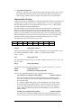
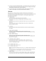
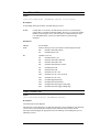
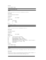
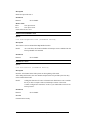
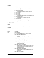
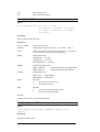
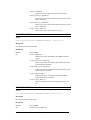
The table below pictures the format of a CGT entry:
DO
Skip
Pause
Se/Diff
Range
NRSE
Gain
Channel
8 bits
1 bit
1 bit
1 bit
2 bits
1 bit
3 bits
4 bits
Channel
Analog Input Channel
Specifies the Analog Input channel to sample. Depending on your configuration you may
have 8 differential channels (AIN1…AIN8), or 16 Single-Ended channels
(AIN1…AIN16)
Gain
Analog Input Gain
This field specifies the gain to apply to the input. Available choices are1x, 2x, 4x, 8x, 16x,
32x, 64x, 128x.
Range
Analog Input Range
Specifies one of the three supported input ranges: ±5 Volts, ±10 Volts or 0…10Volts.
Se/Diff
NRSE
Analog Input Type
Non-Referenced Single Ended Bit
These two bits together determine the type of the analog input channel.
Ground Referenced Single-Ended (GRSE):
Se/Diff=0, NRSE=0
This mode is suggested only for floating signal sources to avoid the ground
loops. For this input type, the reference signal of Instrumentation Amplifier is
the Analog Ground.
To configure a GRSE analog input, connect the high side of the input signal to
the selected analog input channel (AIN1...AIN16), and connect the low side to
any of the Analog Ground pins of the I/O connector. If you use the channels
AIN9…AIN16, switch the appropriate SW1 and SW2 dips off. See Hardware
Manual for more.
Non Referenced Single-Ended (NRSE):
Se/Diff=0, NRSE=1
This mode can be used for grounded signal sources and for floating sources as
well. For this input type, the reference signal of Instrumentation Amplifier is the
10/90
DM7420 Data Acquisition Driver for Windows 95/98/NT
AINSENSE signal. In the case of floating sources, an external resistor is needed
to ground the AINSENSE signal.
To configure an NRSE analog input, connect the high side of the input signal to
the selected analog input channel (AIN1…AIN16), and connect the low side to
the AINSENSE pin of the I/O connector. If you use channels AIN9…AIN16,
switch the appropriate SW1 and SW2 dips off. See Hardware Manual for more.
Differential (DIFF):
Se/Diff=1, NRSE=x
This mode can be useful when the shielding of the signal is important. In
differential mode, you use two analog input channels of the board for an analog
input. AINx and AINx+8, also referred to as AINx+ and AINx-, can be used in
couple for a differential analog input. This way you may have up to 8
differential analog inputs. For this input type, the reference signal of
Instrumentation Amplifier is the AIN- signal.
To configure an NRSE analog input, connect the high side of the analog input to
the selected analog input channel (AIN1+…AIN8+), and connect the low side
to the corresponding AIN- pin (AIN1-/AIN9…AIN8-/AIN16). See Hardware
Manual for more.
Pause
Pause Bit
If this bit is set and pausing is enabled by the EnableCGTPause7420 function, execution
of the Channel-Gain Table stops after executing this entry. Execution is resumed with the
next CGT entry when the programmed Pacer Clock start trigger occurs.
EXAMPLE: Pause Bit can be used when you have two sequence of entries, each to be
executed on a different event (trigger). Suppose that CGT is driven by the
Pacer Clock, and the Pacer Clock is started on the External Trigger. The
External Trigger comes from a device, whose pulses indicate two different
events. Odd pulses indicate an event, on which you want to react by
sampling AIN1 and AIN2, on even pulses you want to sample AIN3, AIN4
and AIN5. In this case, you would create a 5 entry CGT:
Entry #1: AIN1, Pause Bit = 0
Entry #2: AIN2, Pause Bit = 1
Entry #3: AIN3, Pause Bit = 0
Entry #4: AIN4, Pause Bit = 0
Entry #5: AIN5, Pause Bit = 1
In this case, the first pulse on the External Trigger line starts executing the
CGT at the rate of the Pacer Clock. After executing the first two entries,
execution stops and is waiting for the next External Trigger pulse. The
second pulse resumes execution, and entries #3, #4 and #5 are executed at
the rate of the Pacer Clock. Execution pauses again, after executing entry
#5. A third External trigger pulse continues execution with entry #1, and so
on.
NOTE:
When the Channel-Gain Latch is used, or in burst mode, Pause Bit is
ignored.
DM7420 Data Acquisition Driver for Windows 95/98/NT
11/90
Skip
Skip Bit
When the Skip Bit is set, the entry is skipped, which means that the A/D conversion is
performed but the resulting sample is not written into the A/D FIFO. This feature provides
a way to sample multiple channels at different rates without saving unwanted data.
EXAMPLE: In this example, we want to sample AIN1 in every second and AIN4 in
every three seconds. For this end, we must create CGT with six entries:
Entry #1: AIN1, Skip Bit = 0
Entry #2: AIN4, Skip Bit = 1
Entry #3: AIN1, Skip Bit = 0
Entry #4: AIN4, Skip Bit = 1
Entry #5: AIN1, Skip Bit = 0
Entry #6: AIN4, Skip Bit = 0
Next, we set the Pacer Clock to run at 2 Hz (0.5 seconds). This allows us to
sample each channel once per second, the maximum sampling rate required
by one of the channels (pacer clock rate = number of different channels
sampled x fastest sample rate).
The first Pacer Clock pulse starts an A/D conversion according to the
parameters set in the first entry of the Channel-Gain Table, and each
successive clock pulse incrementally steps through the table entries. The
first clock pulse takes a sample on AIN1. The second pulse looks at the
second entry in the table and sees that the Skip Bit is set. Sample is taken,
but is not stored in the FIFO. The third pulse takes a sample on AIN1 again,
the fourth pulse skips the next entry, and the fifth pulse takes our third
reading on AIN1. On the sixth pulse, the Skip Bit is disabled, AIN4 is
sampled and sample is stored to the FIFO. Then the sequence starts over
again with entry #1. Samples are not stored when they are not wanted,
saving memory and eliminating the need to throw away unwanted data.
NOTE:
DO
When the Channel-Gain Latch is used, Skip Bit is ignored.
8-Bit Digital Table
The digital portion of the Channel-Gain Table, also referred to as Digital Table, can be
used to control input expansion boards such as the TMX32 Analog Input Expansion
board. The expansion board is driven at the same speed as the A/D conversions are
performed, with no software overhead.
EXAMPLE: Let us consider the following simple example on driving an analog input
expansion board.
In this example, we have a TMX32 expansion board connected to AIN1 on
the DM7420. We have three signals to sample, one is connected to the first
channel of the expansion board (EAIN1), the second is connected to the
fourth channel of the expansion board (EAIN4) and the third is connected
directly to AIN2 of the DM7420.
We need to create the following Channel-Gain Table:
12/90
DM7420 Data Acquisition Driver for Windows 95/98/NT
Entry #1: AIN1, gain=1, DO=0
Entry #2: AIN1, gain=4, DO=3
Entry #3: AIN2, gain=1, DO=3
Execution, starting with entry #1, samples AIN1 and simultaneously outputs
0 on Digital Port 1. This will cause the expansion board to switch to EAIN1.
Entry #2 will sample AIN1, which is now connected to EAIN1, and
simultaneously outputs 3 on Digital Port 1. As a result, the expansion board
switches to EAIN4.
Next, entry #3 samples AIN2 and outputs 3 on Digital Port 1, which makes
the expansion board to switch (again) to EAIN4.
When executing entry #1 again, AIN1 is sampled which is now connected
to EAIN4, and so on.
To load the Channel-Gain Table you need to follow the steps below:
SetupCgtRow7420(&entry,0,GAIN1,AIN_BIP5,0,GND_SE,0,0,0,0);
˝
WriteCGTAnalog7420(0,entry);
WriteCGTDigital7420(0,0);
// entry#1, analog
// entry#1, digital
SetupCgtRow7420(&entry,0,GAIN4,AIN_BIP5,0,GND_SE,0,0,0,0);
WriteCGTAnalog7420(0,entry);
WriteCGTDigital7420(0,3);
// entry#2, analog
// entry#2, digital
SetupCgtRow7420(&entry,1,GAIN1,AIN_BIP5,0,GND_SE,0,0,0,0);
˝
WriteCGTAnalog7420(0,entry);
WriteCGTDigital7420(0,3);
EnableCGT7420(0,CSC_CGT);
// entry#3, analog
// entry#3, digital
// enable CGT (vs. CGL)
EnableCGTDigital7420(0,CSC_CGT);
// enable Digital Table
˝
˝
NOTE:
If you only need to use the A/D part of the table, you do not have to
program the Digital Table. However, if you only want to use the Digital part
of the table, you must program the A/D part of the table.
NOTE:
When the Channel-Gain Latch is used, Digital Table is ignored.
When using the Channel Gain Table, you should group your entries to maximize the
throughput of your module. Low-level input signals and varying gains are likely to drop
the throughput rate because low level inputs must drive out high level input residual
signals. To maximize throughput:
Keep channels configured for a certain range grouped together, even if they are out of
sequence.
Use external signal conditioning if you are performing high speed scanning of low
level signals. This increases throughput and reduces noise.
DM7420 Data Acquisition Driver for Windows 95/98/NT
13/90
If you have room in the channel-gain table, you can make an entry twice to make sure
that sufficient settling time has been allowed and an accurate reading has been taken.
Set the skip bit for the first entry so that it is ignored.
For best results, do not use the channel-gain table when measuring steady-state
signals. Use the single convert mode to step through the channels.
Interrupts
DM7420 features a Priority Interrupt Controller with interrupt-overrun protection.
Controller can receive interrupt request from up to 15 sources. These 15 sources cover the
most important internal signals of the board plus 3 external signals (highest priority
interrupt source comes first):
A/D FIFO Write
Interrupt is generated when sample enters the A/D FIFO.
This interrupt can be used for reading and processing samples real-time.
CGT Reset
Interrupt is generated when the Channel-Gain Table recycles execution to the first
table entry.
This interrupt can be used for reading and processing a burst of samples from
different channels real-time.
˝
CGT Pause
Interrupt is generated when Channel-Gain Table execution is paused waiting for a
new trigger.
˝
About Counter Countdown
Interrupt is generated when the About Counter counts down to zero.
This interrupt can be used to detect (and react on) the end of sampling when doing
Pre/Port Triggering.
Delay Counter Countdown
Interrupt is generated when the Delay Counter counts down to zero.
This interrupt can be used to detect (and react on) the actual start of sampling when
doing Pre/Port Triggering.
˝
A/D Sample Counter Countdown
Interrupt is generated when the A/D Sample Counter counts down to zero.
This interrupt can be used to count more than 65535 samples by counting the
turnovers of the Sample Counter.
˝
User Timer/Counter 1 Out
User Timer/Counter 1 Out, inverted
User Timer/Counter 2 Out
Interrupt is generated on the ticks of User T/C1 (i.e., when the counter counts down to
zero).
This interrupt gives you a general-purpose means of measuring real time, frequency,
or counting events. It is also intended to use for Pulse output generation.
Digital Interrupt
Interrupt is generated when the Advanced Digital Trigger signals a Digital Interrupt.
This interrupt can be used to detect (and react on) certain patterns on Digital Input
14/90
DM7420 Data Acquisition Driver for Windows 95/98/NT
Port 0.
˝
External Interrupt
Interrupt is generated on the rising edge of the External Interrupt pin of the I/O
connector.
This interrupt is intended for exporting events from an external device.
˝
External Trigger rising-edge
External Trigger falling-edge
Interrupt is generated on a rising/falling edge of the External Trigger pin.
This interrupt is intended for the Gated Mode operation of the Pacer Clock.
Because of the several interrupt sources on the board, a Priority Interrupt Controller was
built to assure even usage all of the interrupt sources.
When the Interrupt Controller receives an interrupt request, it transmits it to the PC
Interrupt Controller (to the IRQ line, which is assigned to the board by the operating
system).
In the Interrupt Service Routine, reading the Interrupt Status Register via a call to
GetITStatus7420, you can identify the causing interrupt source. In this register, there is a
single non-zero bit that indicates the signaling interrupt source. If more than one interrupt
source generates an interrupt at the same time, this register will indicate the highest
priority one. The lower priority request is queued and will appear after acknowledging the
higher priority one.
After identifying the source, the interrupt can be serviced. After servicing, the request
must be acknowledged by calling ClearITMask7420. Failing to do this makes the same
interrupt reoccur repeatedly.
In normal operation, the next interrupt request comes later than acknowledging the current
one. However, if the next interrupt comes before acknowledging the current one, i.e.,
interrupt overrun occurs, you must be aware of it. For this end, DM7420 has an Interrupt
Overrun Register. Reading this register (see GetITOverrun7420) after acknowledging the
request enables you to determine a possible interrupt overflow.
To service interrupts with the DM7420 Driver you do not have to deal with all these
chores. Actually, when you install your interrupt handler, it is not a real Interrupt Service
Routine, since you can not do that under Windows NT. Your handler is an ordinary
routine, which is called by the real Interrupt Service Routine implemented by the DM7420
driver. The driver’s Interrupt Service Routine schedules your interrupt handler for
execution as a separate thread, acknowledges the interrupt to the board’s interrupt
controller and returns. After returning, the scheduled thread starts executing your interrupt
handler.
Pre and Post Triggering
DM7420 offers various triggers for pre/post (about) triggering. The triggering mechanism,
built around the Pacer/Burst Clock circuitry, lets you implement various triggering
schemes.
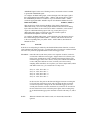
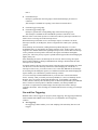
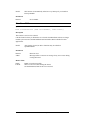
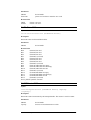
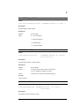
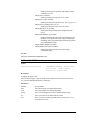
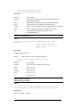
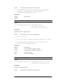
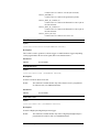
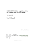
Pre-Triggering
Pre-triggering scheme enables you to start sampling with some delay after an event
(trigger).
DM7420 Data Acquisition Driver for Windows 95/98/NT
15/90
sampling
Start Trigger
This scheme can be useful when you do not want the first couple of samples after the
important event. This can be the case when you know that these samples are noisy or
meaningless because of settling issues.
This scheme is realized by using the Delay Counter. Follow the steps below to set up
for this scheme:
1. Set up the Pacer Clock to start delayed on the desired event.
SetPacerStart7420(hBoard,PCLK_START_D_xxx);
2.
Initialize the Delay Counter for the required number of samples to wait (Delay
Counter counts at the rate of the Pacer Clock).
SetupDelayCounter7420(hBoard,samples);
3.
Arm the Pacer Clock to be ready for receiving the start trigger.
StartPacer7420(hBoard);
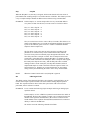
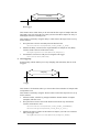
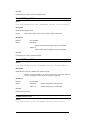
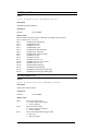
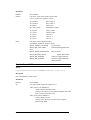
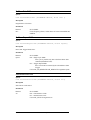
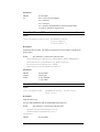
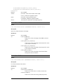
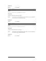
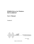
Post-Triggering
Post-triggering scheme enables you to stop sampling with some delay after an event
(trigger).
sampling
Trigger
This scheme is for situations where you want to take a known number of samples after
an important event.
This scheme is realized by using the About Counter. Follow the steps below to set up
for this scheme:
1. Allocate a buffer, which is big enough to hold the desired number of samples
(nsamples) after the event.
2. Set up the Pacer Clock to start on the desired event and to stop when About
Counter counts down to zero.
SetPacerStart7420(hBoard,PCLK_START_SOFTWARE);
SetPacerStop7420(hBoard,PCLK_STOP_A_xxx);
3.
16/90
Initialize the About Counter for the number of samples you want to be collected
after your trigger event.
SetupAboutCounter7420(hBoard,nsamples,TRUE);
DM7420 Data Acquisition Driver for Windows 95/98/NT
4.
Set up a mechanism to copy samples from the A/D FIFO to your sample buffer.
For example, install an interrupt handler to copy data by 512 samples:
SetupSampleCounter7420(hBoard,TC_ADC_SCNT,
ADC_SCNT_FIFO_WRITE,
512,M8254_RATE_GENERATOR);
InstallCallbackIRQHandler7420(hBoard,handler,
IRQM_AD_SCNT);
SetITMask7420(hBoard,IRQM_AD_SCNT);
5.
Arm the Pacer Clock to be ready for receiving the start trigger.
StartPacer7420(hBoard);
When the trigger occurs, About Counter will start and sampling stops after nsamples.
At this point, your sample buffer will contain the data you needed.
If you want to take more than 65,535 samples after the trigger, you also need to do the
following:
3. Change About Counter setup to disable it stopping when it counts down to zero
and install an interrupt handler on About Counter Countdown.
SetupAboutCounter7420(hBoard,nsamples,FALSE);
InstallCallbackIRQHandler7420(hBoard,handler,
IRQM_ABOUT_CNT);
6.
In the About Counter interrupt handler, count the Countdowns and enable About
Counter to stop when the required number of samples has been taken.
EnableAcntStop7420(hBoard,TRUE);
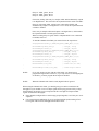
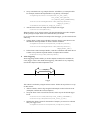
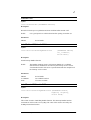
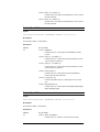
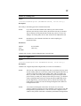
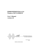
About Triggering
About-triggering scheme enables you to take samples around (before and after) an
event (trigger). This is also called about triggering. This scheme is very frequently
used to take samples around an important event.
sampling
Trigger
This scheme is realized by using the About Counter. Follow the steps below to set up
for this scheme:
1. Allocate a buffer, which is big enough to hold samples to take before the event
(nsamples1) and after the event (nsamples2).
2. Set up the Pacer Clock to start from software, and to stop on the desired trigger
invent.
SetPacerStart7420(hBoard,PCLK_START_SOFTWARE);
SetPacerStop7420(hBoard,PCLK_STOP_A_xxx);
3.
Initialize the About Counter for the number of samples you want to be collected
after your trigger event.
SetupAboutCounter7420(hBoard,nsamples2,TRUE);
DM7420 Data Acquisition Driver for Windows 95/98/NT
17/90
4.
Set up a mechanism to copy samples from the A/D FIFO to your sample buffer.
For example, install an interrupt handler to copy data by 512 samples:
SetupSampleCounter7420(hBoard,TC_ADC_SCNT,
ADC_SCNT_FIFO_WRITE,
512,M8254_RATE_GENERATOR);
InstallCallbackIRQHandler7420(hBoard,handler,
IRQM_AD_SCNT);
SetITMask7420(hBoard,IRQM_AD_SCNT);
5.
Start the Pacer Clock.
StartPacer7420(hBoard);
When the trigger occurs, About Counter will start and sampling stops after nsamples2.
At this point, your sample buffer’s last nsamples1+nsamples2 elements will contain
the data you needed.
If you want to take more than 65,535 samples after the trigger, you also need to do the
following:
3. Change About Counter setup to disable it stopping when it counts down to zero
and install an interrupt handler on About Counter Countdown.
SetupAboutCounter7420(hBoard,nsamples2,FALSE);
InstallCallbackIRQHandler7420(hBoard,handler,
IRQM_ABOUT_CNT);
6.
In the About Counter interrupt handler, count the Countdowns and enable About
Counter to stop when the required number of samples has been taken.
EnableAcntStop7420(hBoard,TRUE);
Advanced Digital Trigger
The bit-programmable Digital I/O Port 0 supports two Advanced Digital Interrupt modes.
Port can be programmed to generate an interrupt when selected port lines match a
programmed value (match mode) or when any of the selected lines changes (event mode).
Mode is selected by the SetDIO0CompareMode7420 function.
When Advanced Digital Interrupt modes enabled (see EnableDIO0Irq7420), digital lines
are sampled at either at 8 MHz or at the rate of User Timer/Counter 1. Clock is selected by
the SetDIO0Clock7420 function. Only lines enabled in the Mask Register (set by
SetDIO0Mask7420) take part in monitoring. With each clock pulse, the digital circuitry
looks at the state of the next Port 0 bits. To provide noise rejection and prevent erroneous
interrupt generation because of noise spikes on the digital lines, a change in the state of
any bit must be seen for two edges of a clock pulse to be recognized by the circuit.
In Event Mode, the enabled Port 0 input lines are monitored for a change. When any of
these lines change, an interrupt is generated and the input pattern is latched into the
Compare Register. You can read the contents of this register with
GetDIO0CompareValue7420 to see which bit caused the interrupt to occur.
In Match Mode, the enabled Port 0 input lines are monitored for the value programmed in
the Compare Register with SetDIO0CompareValue7420 to occur. When lines match this
value, an interrupt is generated.
When Advanced Digital Interrupt mode is not enabled (see EnableDIO0Irq7420), the
Mask Register can be used to preserve a bit’s state, regardless of the digital data written to
Port 0. In addition, external data can be strobed into Port 0 by connecting a trigger pulse
through the External Pacer Clock pin at the External I/O Connector. This data can be read
from the Compare Register with GetDIO0CompareValue7420.
18/90
DM7420 Data Acquisition Driver for Windows 95/98/NT
DM7420 Data Acquisition Driver for Windows 95/98/NT
19/90
Driver API Function Groups
Driver Initialization Functions
OpenBoard7420
CloseBoard7420
GetErrorStatus7420
General Board Control Functions
InitBoard7420
ClearAllIO7420
FIFO Manipulation
GetFifoStatus7420
IsADFIFOEmpty7420
IsADFifoHalfFull7420
IsADFifoFull7420
IsDINFifoEmpty7420
IsDINFifoHalfFull7420
IsDINFifoFull7420
ClearDinFifo7420
ClearADFIFO7420
ReadADData7420
ReadADDataWithMarker7420
GetAutoIncDataByte7420
GetAutoIncDataWord7420
ReadDinFifo7420
A/D Converter
StartConversion7420
SetConversionSelect7420
Channel-Gain Table Manipulation
WriteCGTAnalog7420
WriteCGTLatch7420
WriteCGTDigital7420
EnableCGT7420
EnableCGTDigital7420
EnableCGTPause7420
ResetCGT7420
ClearCGT7420
SetupCgtRow7420
SetChannelGain7420
Pacer Clock Handling
StartPacer7420
StopPacer7420
SetPacerStart7420
SetPacerStop7420
SetPacerRepeat7420
DM7420 Data Acquisition Driver for Windows 95/98/NT
21/90
SetPclkSize7420
SetPacerSource7420
SetPacerRate7420
SetPacerClock7420
Burst Clock Handling
StartBurst7420
SetBurstStart7420
SetBurstRate7420
SetupBurst7420
Delay Counter Functions
LoadDcnt7420
SetupDelayCounter7420
About Counter Functions
EnableAcntStop7420
LoadAcnt7420
SetupAboutCounter7420
Sample Counter Functions
SetAdcntSource7420
LoadAdcnt7420
SetupSampleCounter7420
Digital I/O Functions
ClearDIO7420
ClearDIO0IrqStatus4
EnableDIO0Irq7420
GetDIO0Clock7420
GetDIO0CompareMode7420
GetDIO0CompareValue7420
GetDIO0Direction7420
GetDIO1Direction7420
GetDIO0Mask7420
GetDIOStatus7420
PollDIO07420
ReadDIO07420
ReadDIO17420
SelectDIO0Register7420
SetDIO0Clock7420
SetDIO0CompareMode7420
SetDIO0CompareValue7420
SetPort0Direction7420
SetPort1Direction7420
SetDIO0Direction7420
SetDIO1Direction7420
SetDIO0Mask7420
WriteDIO07420
WriteDIO17420
22/90
DM7420 Data Acquisition Driver for Windows 95/98/NT
High-Speed Digital Input Functions
StartHdin7420
SetHdinStart7420
User Input/Output Functions
ReadUserInput7420
WriteUserOutput7420
SetUout0Source7420
SetUout1Source7420
User Timer-Counter Functions
GetTimerStatus7420
SetUtc0Clock7420
SetUtc0Gate7420
SetUtc1Clock7420
SetUtc1Gate7420
SetUtc2Clock7420
SetUtc2Gate7420
Set8254Divisor7420
Set8254Mode7420
Get8254Mode7420
Get8254Count7420
Get8254Status7420
SetupTimerCounter7420
ReadTimerCounter7420
KickCounter7420
Interrupt Handling
GetITStatus7420
SetITMask7420
ClearITMask7420
ReadITOverrun7420
ClearITOverrun7420
SetEintPolarity7420
EnableDIO0Irq7420
ClearDIO0IrqStatus7420
InstallCallbackIRQHandler7420
InstallCounterIRQHandler7420
RemoveIRQHandler7420
GetIRQCounter7420
External Trigger Configuration Functions
SetEtrgPolarity7420
DM7420 Data Acquisition Driver for Windows 95/98/NT
23/90
24/90
DM7420 Data Acquisition Driver for Windows 95/98/NT
Alphabetical Driver API Functions Reference
DM7420 Data Acquisition Driver for Windows 95/98/NT
25/90
26/90
DM7420 Data Acquisition Driver for Windows 95/98/NT
C
ClearADFIFO7420
Syntax
void ClearADFIFO7420 (RTDHANDLE hBoard);
Description
Dispose all samples from the A/D FIFO.
NOTE:
Reading from an empty FIFO (e.g., with ReadADData7420,
ReadADDataWithMarker7420, GetAutoIncDataByte7420 or
GetAutoIncDataWord7420) results in indeterministic data.
Parameters
hBoard:
device handle
ClearAllIO7420
Syntax
void ClearAllIO7420 (RTDHANDLE hBoard);
Description
Software reset of the board.
Parameters
hBoard:
device handle
ClearCGT7420
Syntax
void ClearCGT7420 (RTDHANDLE hBoard);
Description
Clear A/D Channel-Gain Table.
This function removes all entries from the CGT. Use this function before reprogramming
the CGT. This is the only way to remove entries from the CGT. There is no way to insert
/remove a single CGT entry or change it in place.
NOTE:
This function clears the Digital part of the CGT.
Parameters
hBoard:
device handle
See Also
Channel-Gain Circuitry
DM7420 Data Acquisition Driver for Windows 95/98/NT
27/90
ClearDinFifo7420
Syntax
void ClearDinFifo7420 (RTDHANDLE hBoard);
Description
Remove all samples from the High Speed Digital Input FIFO.
NOTE:
Reading from an empty FIFO (e.g., with ReadDinFifo7420) results in
undeterministic data.
Parameters
hBoard:
device handle
ClearDIO7420
Syntax
void ClearDIO7420 (RTDHANDLE hBoard);
Description
Reset the Digital I/O chip.
It programs all I/O lines for input and programs the Advanced Digital Trigger for Event
Mode.
NOTE:
It does not clear a pending interrupt. You must make a call to
ClearDIO0IrqStatus7420 explicitly.
Parameters
hBoard:
device handle
ClearDIO0IrqStatus7420
Syntax
void ClearDIO0IrqStatus7420 (RTDHANDLE hBoard);
Description
Clears the Digital IRQ status flag. You must acknowledge Digital Interrupts by calling this
function. Failing to do this, no more Digital Interrupts will be generated by the Digital I/O
chip.
Parameters
hBoard:
device handle
See Also
Advanced Digital Trigger
28/90
DM7420 Data Acquisition Driver for Windows 95/98/NT
ClearITMask7420
Syntax
void ClearITMask7420 (RTDHANDLE hBoard, uint16 mask);
Description
Acknowledge interrupts from the specified interrupt sources.
NOTE:
Usually there is no need to call this function, because it is automatically
called when you install an interrupt handler. However, if you do not install a
handler for an interrupt source, but interrupts are enabled from that source
(see SetITMask7420), you may need this function to acknowledge
interrupts.
Parameters
hBoard:
mask:
D2
device handle
mask of interrupt sources for which to acknowledge interrupts:
D0
(0x0001) ADC FIFO Write
D1
(0x0002) Reset CGT
(0x0004) reserved
D3
(0x0008) Pause CGT
D4
(0x0010) ADC FIFO half-full
D5
(0x0020) ADC FIFO full
D6
(0x0040) ADC Sample Counter
D7
(0x0080) Not used
D8
(0x0100) Not used
D9
(0x0200) User TC1 out
D10
(0x0400) User TC1 out, inverted
D11
(0x0800) User TC2 out
D12
(0x1000) Digital Interrupt
D13
(0x2000) External Interrupt
D14
(0x4000) External Trigger rising-edge
D15
(0x8000) External Trigger falling-edge
ClearITOverrun7420
Syntax
void ClearITOverrun7420 (RTDHANDLE hBoard);
Description
Clear Interrupt Overrun Register.
The Interrupt Overrun Register is for detecting interrupt overrun conditions. If an interrupt
occurs from a source and an other interrupt occurs from that source before the first
interrupt is acknowledged, the appropriate bit in the Interrupt Overrun Register goes to 1
indicating overrun.
DM7420 Data Acquisition Driver for Windows 95/98/NT
29/90
NOTE:
This function is automatically called on every interrupt if you install an
interrupt handler.
Parameters
hBoard:
device handle
CloseBoard7420
Syntax
BOOL CloseBoard7420 (LONG DeviceNumber, LPSTR szBuf);
Description
This routine is used to close a board.
Call this function when you finished to use a board. CloseBoard7420 releases no longer
needed system resources and the DM7420 itself and makes them available for other
applications.
NOTE:
After closing a board, no driver functions may be called but
OpenBoard7420.
Parameters
hBoard:
szBuf:
Board to close.
Message buffer to return error message if any error occurs during
closing the board.
Return Value
TRUE
FALSE
30/90
Board is closed successfully.
There was an error while closing the board.
See GetErrorStatus7420 for the error occurred.
DM7420 Data Acquisition Driver for Windows 95/98/NT
E
EnableAcntStop7420
Syntax
void EnableAcntStop7420 (RTDHANDLE hBoard, uint16 enable);
Description
Enable/disable About Counter to stop when it counts down to zero. Default setting is
enabled.
The About Counter is a 16-bit down counter that stops or reloads the initial count value
after counting down to zero. The About Counter, counting at the rate of the Pacer Clock,
can be used to count samples. When About Counter stop enabled, the counter stops when
it counts down to zero. If you disable About Counter Stop, the counter keeps reloading the
initial counter value when it reaches zero. In both cases, you may program the board to
generate an interrupt. When stop disabled, you can install your own interrupt handler for
the About Counter countdown event and keep track of the turnovers. Use this mode to
extend the counting capability highest number than 65535. In the interrupt handler, when
the counter counted the desired number of samples, you have to reprogram the counter to
the fractional number of samples and enable Sample Counter stop.
Example
Suppose you want to count 500,000 samples with the About Counter. In this case first you
load the initial count of 65,535, disable About Counter stop and install an interrupt handler
for About Counter Count-Down. In the interrupt handler, you maintain a counter for the
turnovers. After 500,000/65,535 = 7, you load the fractional count 500,000 – 7*65,535 =
41,255 and enable About Counter stop.
Parameters
hBoard:
enable:
device handle
0 = Stop enabled
1 = Stop disabled
EnableCGT7420
Syntax
void EnableCGT7420 (RTDHANDLE hBoard, uint16 enable);
Description
Select Channel Gain Table or Channel-Gain Latch to use for A/D sampling.
Parameters
hBoard:
enable:
device handle
CSC_LATCH (0)
Channel Gain Table disabled Channel Gain Latch
enabled.
CSC_CGT (1)
Channel Gain Table enabled Channel Gain Latch
disabled.
DM7420 Data Acquisition Driver for Windows 95/98/NT
31/90
See Also
Channel-Gain Circuitry, EnableCGTDigital7420.
EnableCGTDigital7420
Syntax
void EnableCGTDigital7420 (RTDHANDLE hBoard, uint16 enable);
Description
Enable/disable Digital Table.
NOTE:
This function has no effect if you use the Channel-Gain Latch.
Parameters
hBoard:
enable:
device handle
FALSE (0)
Digital Table disabled, Digital I/O P1 port enabled.
TRUE (1)
Digital Table enabled, Digital I/O P1 port disabled.
See Also
Channel-Gain Circuitry, EnableCGT7420
EnableCGTPause7420
Syntax
void EnableCGTPause7420 (RTDHANDLE hBoard, uint16 enable);
Description
Enable/disable using the Channel-Gain Table Pause Bit.
NOTE: Set the Pause Bit if you want to stop an entry in the table and wait
for the next trigger. In burst mode, the pause bit is ignored.
Parameters
hBoard:
enable:
device handle
FALSE (0)
TRUE (1)
Disable interpreting CGT Pause Bit.
Enable interpreting CGT Pause Bit.
See Also
Channel-Gain Circuitry
EnableDIO0Irq7420
Syntax
void EnableDIO0Irq7420 (RTDHANDLE hBoard, BOOL enable);
32/90
DM7420 Data Acquisition Driver for Windows 95/98/NT
Description
Enable/disable Bit Programmable Digital I/O to generate interrupts.
Parameters
hBoard:
enable:
device handle
FALSE (0)
TRUE (1)
disable
enable
See Also
Advanced Digital Trigger
DM7420 Data Acquisition Driver for Windows 95/98/NT
33/90
34/90
DM7420 Data Acquisition Driver for Windows 95/98/NT
G
Get8254Count7420
Syntax
uint16 Get8254Count7420 (RTDHANDLE hBoard, int counter);
Description
Read current counter value of a 8254 Timer/Counter.
Parameters
hBoard:
counter:
device handle
One of the 16-bit timer/counters of the board.
Use TC_XXXX for argument 'counter'.
Get8254Mode7420
Syntax
uint8 Get8254Mode7420 (RTDHANDLE hBoard, int counter);
Description
Read back programmed operation mode of a 8254 Timer/Counter.
Parameters
hBoard:
counter:
device handle
One of the 16-bit timer/counters of the board.
Use TC_XXXX for argument 'counter'.
Get8254Status7420
Syntax
uint8 Get8254Status7420 (RTDHANDLE hBoard, int counter);
Description
Read status of a 8254 Timer/Counter.
Parameters
hBoard:
counter:
device handle
One of the 16-bit timer/counters of the board.
Use TC_XXXX for argument 'counter'.
GetAutoIncDataByte7420
Syntax
unsigned GetAutoincDataByte7420
(RTDHANDLE hBoard,
AutoincSetup *autoincsetup, uint16 DataNum);
DM7420 Data Acquisition Driver for Windows 95/98/NT
35/90
Description
This routine is used to read a block of samples from the A/D FIFO.
Parameters
hBoard:
autoincsetup:
DataNum:
device handle
parameters for auto-increment command
number of data item to read
GetAutoIncDataWord7420
Syntax
unsigned GetAutoIncDataWord7420
(RTDHANDLE hBoard,
AutoincSetup *autoincsetup,
uint16 DataNum);
Description
This routine is used to get the data with auto-increment driver mode.
Parameters
hBoard:
autoincsetup:
DataNum:
device handle
parameters for auto-increment command
number of data item to read
GetDIO0Clock7420
Syntax
uint8 GetDIO0Clock7420 (RTDHANDLE hBoard);
Description
Read Clock set for the bit programmable Digital I/O (port 0).
Parameters
hBoard:
device handle
Return Value
0
1
- 8 MHz On-board Oscillator
- User TC Counter 1
GetDIO0CompareMode7420
Syntax
uint8 GetDIO0CompareMode7420 (RTDHANDLE hBoard);
Description
Read port 0 compare mode.
Parameters
hBoard:
36/90
device handle
DM7420 Data Acquisition Driver for Windows 95/98/NT
Return Value
0
1
- Event Mode
- Match Mode
GetDIO0CompareValue7420
Syntax
uint8 GetDIO0CompareValue7420 (RTDHANDLE hBoard);
Description
Read pattern of Port 0 I/O lines for Digital Interrupt generation.
Parameters
hBoard:
device handle
Return Value
pattern
GetDIO0Direction7420
Syntax
uint8 GetDIO0Direction7420 (RTDHANDLE hBoard);
Description
Return programmed Digital I/O Port 0 line directions.
Parameters
hBoard:
device handle
Return Value
8-bit direction mask:
Bit = 0 – line is programmed for input
Bit = 1 – line is programmed for output
GetDIO0Mask7420
Syntax
uint8 GetDIO0Mask7420 (RTDHANDLE hBoard);
Description
Return Digital Interrupt mask for Port 0 I/O lines.
Parameters
hBoard:
device handle
Return Value
8-bit interrupt mask:
Bit = 0 - line is disabled to take part in Digital Interrupt generation
Bit = 1 - line is enabled to take part in Digital Interrupt generation
DM7420 Data Acquisition Driver for Windows 95/98/NT
37/90
See Also
Advanced Digital Trigger
GetDIO1Direction7420
Syntax
uint8 GetDIO1Direction7420 (RTDHANDLE hBoard);
Description
Return Digital I/O Port 1 direction.
Parameters
hBoard:
device handle
Return Value
Bit 0
Bit 1..7
port direction
0
input
1
output
0
GetDIOStatus7420
Syntax
uint8 GetDIOStatus7420 (RTDHANDLE hBoard);
Description
Read Digital I/O status.
Parameters
hBoard:
device handle
Return Value
D0..D1
D2
D3
D4
D5
D6
D7
register opened for programming
Port 1 direction (0 - input, 1 - output)
Digital IRQ Mode (0 - Event, 1 - Match)
Digital IRQ Enable (0 - disabled, 1 - enabled)
Digital Sample Clock Select (0 - 8MHz oscillator, 1 - User TC Counter 1)
Digital IRQ Status (0 - no IRQ, 1 - IRQ)
Strobe Status
See Also
Advanced Digital Trigger
GetErrorStatus7420
Syntax
BOOL GetErrorStatus7420 (RTDHANDLE hBoard, LONG *ErrorCode);
Description
Return last error code for a given board and clears the internal error status variable (i.e., a
second call to this function will return FALSE, indicating no error)..
38/90
DM7420 Data Acquisition Driver for Windows 95/98/NT
Parameters
hBoard:
ErrorCode:
device handle
pointer to a location to return the error code.
Return Value
TRUE
FALSE
If there is an error.
If there is no error.
GetFifoStatus7420
Syntax
uint16 GetFifoStatus7420 (RTDHANDLE hBoard);
Description
Return the status of all board FIFO buffers.
Parameters
hBoard:
device handle
Return Value
Bit 0
(0x0001) Not used
Bit 1
(0x0002) Not used
Bit 2
(0x0004) Not used
Bit 3
(0x0008) 0 (reserved)
Bit 4
(0x0010) Not used
Bit 5
(0x0020) Not used
Bit 6
(0x0040) Not used
Bit 7
(0x0080) 0 (reserved)
Bit 8
(0x0100) ADC FIFO not empty
Bit 9
(0x0200) ADC FIFO not half empty
Bit 10
(0x0400) ADC FIFO not full
Bit 11
(0x0800) 0 (reserved)
Bit 12
(0x1000) DIN FIFO not empty
Bit 13
(0x2000) DIN FIFO not half empty
Bit 14
(0x4000) DIN FIFO not full
Bit 15
(0x8000) 0 (reserved)
See FS_XXXX symbolic constants.
GetIRQCounter7420
Syntax
void GetIRQCounter7420 (RTDHANDLE hBoard, IRQSetup
*irqsetup);
Description
Return the counter incremented by the interrupt handler. The counter is an 8-bit counter.
Parameters
hBoard:
irqsetup:
device handle
structure to return Parameters to caller
DM7420 Data Acquisition Driver for Windows 95/98/NT
39/90
GetITStatus7420
Syntax
uint16 GetITStatus7420 (RTDHANDLE hBoard);
Description
Read Interrupt Status Register.
Parameters
hBoard:
device handle
Return Value
Return a mask of interrupt sources which have a pending interrupt request
(bit = 0-inactive, bit = 1-active):
Bit 0
(0x0001) ADC FIFO Write
Bit 1
(0x0002) Reset CGT
Bit 2
(0x0004) reserved
Bit 3
(0x0008) Pause CGT
Bit 4
(0x0010) ADC FIFO half-full
Bit 5
(0x0020) ADC FIFO full
Bit 6
(0x0040) ADC Sample Counter
Bit 7
(0x0080) Not used
Bit 8
(0x0100) Not used
Bit 9
(0x0200) User TC1 out
Bit 10
(0x0400) User TC1 out, inverted
Bit 11
(0x0800) User TC2 out
Bit 12
(0x1000) Digital Interrupt
Bit 13
(0x2000) External Interrupt
Bit 14
(0x4000) External Trigger rising-edge
Bit 15
(0x8000) External Trigger falling-edge
GetTimerStatus7420
Syntax
uint16 GetTimerStatus7420 (RTDHANDLE hBoard);
Description
Read Timer Counters Status.
Parameters
hBoard:
device handle
Return Value
Bit 0
Bit 1
Bit 2
40/90
Pacer Clock Gate status:
0 – clock is gated (not running)
1 – clock is running
Burst Clock Gate status:
0 – clock is gated (not running)
1 – clock is running
Pacer Clock Delayed Start Trigger status:
0 - delay over
1 - delay in progress
DM7420 Data Acquisition Driver for Windows 95/98/NT
Bit 3
Pacer Clock About Trigger status:
0 – completed
1 – in progress
Bit 4
Pacer Clock Shutdown Flag status:
0 - Pacer Clock can be start triggered only by Software Pacer Start
Command
1 - Pacer Clock can be start triggered
See TS_XXXX symbolic constants.
DM7420 Data Acquisition Driver for Windows 95/98/NT
41/90
42/90
DM7420 Data Acquisition Driver for Windows 95/98/NT
I
InitBoard7420
Syntax
void InitBoard7420 (RTDHANDLE hBoard);
Description
Resets the board to power up defaults and clears all FIFO buffers and the CGT.
NOTE:
It is a good practice to call this function after opening a board for use.
Parameters
hBoard:
device handle
InstallCallbackIRQHandler7420
Syntax
void InstallCallbackIRQHandler7420
(RTDHANDLE hBoard,
isr_t handler,
uint16 mask);
Description
Install interrupt handler function.
NOTE:
The handler parameter is not a real interrupt handler. It is a callback
function that is scheduled for execution by the interrupt service routine.
Your handler function will run in a separate thread after the completion of
the interrupt service routine.
Parameters
hBoard:
isrT handler:
mask:
device handle
user callback function
IT sources to enable
InstallCounterIRQHandler7420
Syntax
void InstallCounterIRQHandler7420 (RTDHANDLE hBoard,
IRQSetup *irqsetup,
uint16 mask);
Description
This routine is used to install IRQ handler function. This interrupt handler function
increments an 8-bit counter on every IRQ. The value of the counter can read by the
GetIRQCounter7420 function.
DM7420 Data Acquisition Driver for Windows 95/98/NT
43/90
Parameters
hBoard:
irqsetup:
mask:
device handle
return Parameters to caller
IT sources to enable
IsADFifoEmpty7420
Syntax
uint16 IsADFifoEmpty7420 (RTDHANDLE hBoard);
Description
This routine checks to see if the A/D FIFO is empty.
Parameters
hBoard:
device handle
Return Value
TRUE (non-zero) if the A/D FIFO is empty.
IsADFifoFull7420
Syntax
BOOL IsADFifoFull7420 (RTDHANDLE hBoard);
Description
This routine checks to see if the A/D FIFO is full.
Parameters
hBoard:
device handle
Return Value
TRUE (non-zero) if the A/D FIFO is full.
IsADFifoHalfFull7420
Syntax
BOOL IsADFifoHalfFull7420 (RTDHANDLE hBoard);
Description
This routine checks to see if the A/D FIFO is half-full.
Parameters
hBoard:
device handle
Return Value
TRUE (non-zero) if the A/D FIFO is half-full.
44/90
DM7420 Data Acquisition Driver for Windows 95/98/NT
IsDINFifoEmpty7420
Syntax
BOOL IsDINFifoEmpty7420 (RTDHANDLE hBoard);
Description
This routine checks to see if the High Speed Digital Input FIFO is empty.
Parameters
hBoard:
device handle
Return Value
TRUE (non-zero) if the High Speed Digital Input FIFO is empty.
IsDINFifoFull7420
Syntax
BOOL IsDINFifoFull7420 (RTDHANDLE hBoard);
Description
This routine checks to see if the High Speed Digital Input FIFO is full.
Parameters
hBoard:
device handle
Return Value
TRUE (non-zero) if the High Speed Digital Input FIFO is full.
IsDINFifoHalfFull7420
Syntax
BOOL IsDINFifoHalfFull7420 (RTDHANDLE hBoard);
Description
This routine checks to see if the High Speed Digital Input FIFO is half full.
Parameters
hBoard:
device handle
Return Value
TRUE (non-zero) if the High Speed Digital Input FIFO is half full.
DM7420 Data Acquisition Driver for Windows 95/98/NT
45/90
46/90
DM7420 Data Acquisition Driver for Windows 95/98/NT
K
KickCounter7420
Syntax
void KickCounter7420 ( RTDHANDLE hBoard, int counter);
Description
Results one clock signal to the designated counter. After writing a new count value (see
Set8254Divisor7420) to a counter, this function results in loading the initial count into the
counter.
NOTE:
This feature is supported only for the sample counters.
Parameters
hBoard:
counter:
device handle
one of the following counters:
TC_ADC_SCNT
A/D Sample Counter
TC_ACNT
About Counter
TC_DCNT
Delay Counter
DM7420 Data Acquisition Driver for Windows 95/98/NT
47/90
48/90
DM7420 Data Acquisition Driver for Windows 95/98/NT
L
LoadAcnt7420
Syntax
void LoadAcnt7420 (RTDHANDLE hBoard);
Description
Load A/D About Counter divisor.
After setting the About Counter divisor call this function to properly load the divisor.
Parameters
hBoard:
device handle
LoadAdcnt7420
Syntax
void LoadAdcnt7420 (RTDHANDLE hBoard);
Description
Load A/D Sample Counter divisor.
After setting the A/D Sample Counter divisor, call this function to properly load the
divisor.
NOTE:
The output of the A/D sample counter can be an interrupt source, so at the
end of the count-down process an interrupt may be generated.
Parameters
hBoard:
device handle
LoadDcnt7420
Syntax
void LoadDcnt7420 (RTDHANDLE hBoard);
Description
Load Delay Counter divisor.
After setting the Delay Counter divisor, call this function to properly load the divisor.
Parameters
hBoard:
device handle
DM7420 Data Acquisition Driver for Windows 95/98/NT
49/90
50/90
DM7420 Data Acquisition Driver for Windows 95/98/NT
O
OpenBoard7420
Syntax
BOOL OpenBoard7420
(LONG DeviceNumber, BOOL LoadDevice,
LPSTR szBuf, BoardConfig *boardconfig);
Description
This routine is used to open board. This function must be called before any API function
call. At the end of the application program, the board must be closed with the
CloseBoard7420 function.
Parameters
DeviceNumber:
LoadDevice:
szBuf:
boardconfig:
Device number to load. Installed devices are numbered from 0 in
the system registry.
Load/not load the WinRT driver.
message buffer to return error message.
Pointer to a BoardConfig structure to return configuration
information about the board. Use this argument if you need to
know the Operating System resources allocated to the board. Pass
NULL for this argument if you do not need this information.
DM7420 Data Acquisition Driver for Windows 95/98/NT
51/90
52/90
DM7420 Data Acquisition Driver for Windows 95/98/NT
P
PollDIO07420
Syntax
void PollDIO07420
( RTDHANDLE hBoard, uint8 *direction,
uint8 *mask, uint8 *mode, uint8
*compare,
uint8 *clock, uint8 *irq,
uint8 *itstatus );
Description
Return Digital I/O Port 0 status.
Parameters
hBoard:
direction:
mask:
mode:
compare:
clock:
irq:
itstatus:
device handle
Returns the programmed direction mask for the 8 I/O lines (see
GetDIO0Direction7420):
Bit = 0 – line is programmed for input.
Bit = 1 – line is programmed for output.
Returns the Digital Interrupt mask for Port 0 I/O lines (see
GetDIO0Mask7420):
Bit = 0 - line is disabled to take part in Digital Interrupt generation.
Bit = 1 - line is enabled to take part in Digital Interrupt generation.
Returns Advanced Digital Trigger mode (see
GetDIO0CompareMode7420):
0 – Event mode
1 – Mask mode
Returns the programmed value of the Compare Register (see
GetDIO0CompareValue7420).
Returns the programmed Advanced Digital Trigger clock (see
GetDIO0Clock7420):
0 – 8 MHz On-board Oscillator
1 – User TC Counter 1
Returns the Digital I/O Port 0 IRQ Status (see
GetDIO0Status7420):
0 - no IRQ
1 - IRQ
(return value)
DM7420 Data Acquisition Driver for Windows 95/98/NT
53/90
54/90
DM7420 Data Acquisition Driver for Windows 95/98/NT
R
ReadADData7420
Syntax
int ReadADData7420 (RTDHANDLE hBoard);
Description
Read sample (12-bit) from the A/D FIFO.
Parameters
hBoard:
device handle
Return Value
Signed 12 bit A/D Data.
See Also
ReadADDataWithMarker7420
ReadADDataWithMarker7420
Syntax
int16 ReadADDataWithMarker7420 (RTDHANDLE hBoard);
Description
Read A/D FIFO data and data marker bits.
Parameters
hBoard:
device handle
Return Value
Signed 12 bit AD Data and 3 bit Data Marker.
See Also
ReadADData7420
ReadDinFifo7420
Syntax
uint16 ReadDinFifo7420 (RTDHANDLE hBoard);
Description
Read a block of samples from the High Speed Digital Input FIFO.
NOTE:
You must ensure that the FIFO contains at least nSamples samples.
Parameters
hBoard:
device handle
DM7420 Data Acquisition Driver for Windows 95/98/NT
55/90
See Also
ReadDinFifoBlock7420
ReadDIO07420
Syntax
uint8 ReadDIO17420 (RTDHANDLE hBoard);
Description
Read Digital I/O Port 0 digital input lines.
NOTE:
For lines programmed for output, the current value of the line is returned.
Parameters
hBoard:
device handle
Return Value
8-bit port value (bit mask).
ReadDIO17420
Syntax
uint8 ReadDIO17420 (RTDHANDLE hBoard);
Description
Read Port 1 digital input lines.
Parameters
hBoard:
device handle
Return Value
8-bit port value.
ReadITOverrun7420
Syntax
uint16 ReadITOverrun7420 (RTDHANDLE hBoard);
Description
Read the Interrupt Overrun Register.
Parameters
hBoard:
device handle
Return Value
Returns a mask of IT sources which have been overrun.
Bit 0
(0x0001) ADC FIFO Write
Bit 1
(0x0002) Reset CGT
Bit 2
(0x0004) reserved
Bit 3
(0x0008) Pause CGT
56/90
DM7420 Data Acquisition Driver for Windows 95/98/NT
Bit 4
Bit 5
Bit 6
Bit 7
Bit 8
Bit 9
Bit 10
Bit 11
Bit 12
Bit 13
Bit 14
Bit 15
(0x0010) ADC FIFO half-full
(0x0020) ADC FIFO full
(0x0040) ADC Sample Counter
(0x0080) Not used
(0x0100) Not used
(0x0200) User TC1 out
(0x0400) User TC1 out, inverted
(0x0800) User TC2 out
(0x1000) Digital Interrupt
(0x2000) External Interrupt
(0x4000) External Trigger rising-edge
(0x8000) External Trigger falling-edge
See Also
ClearITOverrun7420
ReadTimerCounter7420
Syntax
void ReadTimerCounter7420
(RTDHANDLE hBoard, int counter,
uint8 *mode, uint16 *count );
Description
Read back programmed operation mode and current counter value of a 8254
Timer/Counter.
Parameters
hBoard:
counter:
mode:
count:
device handle
One of the 16-bit timer/counters of the board.:
TC_PCLK16
Pacer Clock 0
TC_PCLK32
Pacer Clock 1
TC_BCLK
Burst Clock
TC_ADC_SCNT
A/D Sample counter
TC_DCNT
Delay Counter
TC_ACNT
About Counter
TC_UTC0
User TC 0
TC_UTC1
User TC 1
TC_UTC2
User TC 2
Pointer to location to return counter mode.
Pointer to location to return current count
NOTE: This is not the initial count (or divisor) of the counter.
There is no way to read initial count from a 8254 Timer/Counter.
ReadUserInput7420
Syntax
uint16 ReadUserInput7420 (RTDHANDLE hBoard);
DM7420 Data Acquisition Driver for Windows 95/98/NT
57/90
Description
Read User Input Line 0 & 1.
Parameters
hBoard:
device handle
Return Value
Bit 0
User input 0 state.
Bit 1
User input 1 state.
All the other bits are zeros.
RemoveIRQHandler7420
Syntax
void RemoveIRQHandler7420 (RTDHANDLE hBoard);
Description
This routine is used to uninstall the IRQ handler function.
NOTE:
As a side effect, this function disables all interrupt sources enabled when the
interrupt handler was installed.
Parameters
hBoard:
device handle
ResetCGT7420
Syntax
void ResetCGT7420 (RTDHANDLE hBoard);
Description
Reset the A/D Channel Gain Table pointer to the beginning of the table.
After calling this function, the next channel sampled is that of specified by the first entry
in the Channel-Gain Table.
NOTE:
Calling this function will cause a Channel-Gain Table Reset event. Consider
this if you have a sample counter (A/D Sample Counter or the About
Counter) configured to count these events or you enabled this event to be an
interrupt source.
Parameters
hBoard:
device handle
See Also
Channel-Gain Circuitry
58/90
DM7420 Data Acquisition Driver for Windows 95/98/NT
S
SelectDIO0Register7420
Syntax
void SelectDIO0Register7420 ( RTDHANDLE hBoard, int aReg );
Description
Program digital control register.
Parameters
hBoard:
device handle
aReg:
0 - Clear Command
1 - Direction Register
2 - Mask Register
3 - Compare Register
Set8254Divisor7420
Syntax
void Set8254Divisor7420
(RTDHANDLE hBoard, int counter,
uint16 divisor);
Description
Load an initial count in a Timer/Counter .
Parameters
hBoard:
counter:
divisor:
device handle
One of the 16-bit timer/counters of the board.
Use TC_XXXX for argument 'counter'.
16-bit divisor to divide clock input frequency.
See Also
Timer/Counters
Set8254Mode7420
Syntax
void Set8254Mode7420
(RTDHANDLE hBoard, int counter,
uint8 mode);
Description
Load count in Timer/Counter 0 (8-bit).
DM7420 Data Acquisition Driver for Windows 95/98/NT
59/90
Parameters
hBoard:
counter:
mode
device handle
One of the 16-bit timer/counters of the board.
Use TC_XXXX for argument 'counter'.
TC_PCLK16
Pacer Clock 0
TC_PCLK32
Pacer Clock 1
TC_BCLK
Burst Clock
TC_ADC_SCNT
A/D Sample counter
TC_DCNT
Delay Counter
TC_ACNT
About Counter
TC_UTC0
User TC 0
TC_UTC1
User TC 1
TC_UTC2
User TC 2
One of the 6 8254 operation modes.
Use M8254_XXXX for argument 'mode':
M8254_EVENT_COUNTER
Event Counter
M8254_HW_ONE_SHOT
Hardware-Retriggerable OneShot
M8254_RATE_GENERATOR
Rate Generator
M8254_SQUARE_WAVE
Square Wave Mode
M8254_SW_STROBE
Software Triggered Strobe
M8254_HW_STROBE
Hardware Triggered Strobe
(Retriggerable)
SetAdcntSource7420
Syntax
void SetAdcntSource7420 (RTDHANDLE hBoard, uint16 src);
Description
Select A/D Sample Counter source.
Parameters
hBoard:
src:
60/90
device handle
Use ADC_SCNT_XXXX for argument 'src':
ADC_SCNT_CGT_RESET (0)
Count Channel Gain Table resets.
Counter counts down by one when the Channel-Gain table
turns over to the first table entry.
ADC_SCNT_FIFO_WRITE (1)
Count A/D FIFO writes.
Counter counts down by one when a new sample is
entered in the FIFO.
DM7420 Data Acquisition Driver for Windows 95/98/NT
SetBurstRate7420
Syntax
void SetBurstRate7420 ( RTDHANDLE hBoard, float rate );
Description
Program the burst clock rate.
Parameters
hBoard:
rate:
device handle
Frequency value (Hertz) between 122Hz and 600KHz.
SetBurstStart7420
Syntax
void SetBurstStart7420 (RTDHANDLE hBoard, uint16 src);
Description
Select Burst Clock start trigger.
NOTE:
There is no programmable stop trigger for the Burst Clock. The Burst Clock
automatically stops when the Channel-Gain Table resets to its first entry.
Parameters
hBoard:
src:
device handle
Use BCLK_START_XXXX for argument 'src'.
BCLK_START_SOFTWARE (0x0)
Calling the StartBurst7420 function starts Burst Clock.
BCLK_START_PCLK (0x1)
Burst Clock is started on every Pacer Clock tick.
BCLK_START_ETRIG (0x2)
Burst Clock is started by the External Trigger line.
BCLK_START_DIGITAL_IT (0x3)
Burst Clock is started when a Digital Interrupt occurs.
BCLK_START_SBUS0 (0x4)
BCLK_START_SBUS1 (0x5)
BCLK_START_SBUS2 (0x6)
Burst Clock is started by a rising edge on Synchron Bus
line 0/1/2.
See Also
Channel-Gain Circuitry
DM7420 Data Acquisition Driver for Windows 95/98/NT
61/90
SetChannelGain7420
Syntax
void SetChannelGain7420
Channel,
(RTDHANDLE hBoard, uint16
uint16 Gain, uint16 Range,
uint16 Se_Diff );
Description
This routine loads the channel/gain latch.
Parameters
hBoard:
Channel:
Gain:
Range:
Se_Diff:
device handle
One of the 16 Analog Input channels (0 – AIN1, 1 – AIN2, etc.).
Gain value to apply on the Analog Input channel.
Valid gains are 1, 2, 4, 8, 16, 32, 64, 128.
Analog Input range.
Valid values are:
0 to +5 Volts
0 to +10 Volts
-5 to +5 Volts
-10 to +10 Volts
Analog Input channel type:
Single-Ended
Differential
SetConversionSelect7420
Syntax
void SetConversionSelect7420 (RTDHANDLE hBoard, uint16
Select);
Description
Select A/D Conversion start signal.
Parameters
hBoard:
Select:
62/90
device handle
ADC_START_SOFTWARE (0x0)
One A/D conversion is started by a call to
StartConversion7420.
ADC_START_PCLK (0x1)
A/D conversions are started by the Pacer Clock.
ADC_START_BCLK (0x2)
A/D conversions are started by the Burst Clock.
ADC_START_DIGITAL_IT (0x3)
One A/D conversion is started when a Digital Interrupt
occurs.
DM7420 Data Acquisition Driver for Windows 95/98/NT
NOTE: Remember to acknowledge the Digital Interrupt
by calling ClearDIO0IrqStatus7420. Otherwise, no newer
Digital Interrupt is generated.
ADC_START_SBUS0 (0x6)
ADC_START_SBUS1 (0x7)
ADC_START_SBUS2 (0x8)
The A/D converter is controlled by the signal on
Synchron Bus line 0/1/2. Conversion started on a rising
edge.
SetDIO0Clock7420
Syntax
void SetDIO0Clock7420 (RTDHANDLE hBoard, uint8 src);
Description
Select clock for the Advanced Digital Trigger.
Parameters
hBoard:
src:
device handle
0 - 8 MHz On-board Oscillator
1 - User TC Counter 1
See Also
Advanced Digital Trigger
SetDIO0CompareMode7420
Syntax
void SetDIO0CompareMode7420 (RTDHANDLE hBoard, uint8 mode);
Description
Programs port 0 compare mode. This register is used for the Advanced Digital Interrupt
modes.
Parameters
hBoard:
mode:
device handle
0 - Event Mode
1 - Match Mode
See Also
Advanced Digital Trigger
SetDIO0CompareValue7420
Syntax
void SetDIO0CompareValue7420 (RTDHANDLE hBoard, uint8
compare);
DM7420 Data Acquisition Driver for Windows 95/98/NT
63/90
Description
Program Port 0 compare value.
Parameters
hBoard:
compare:
device handle
See Also
Advanced Digital Trigger
SetDIO0Direction7420
Syntax
void SetDIO0Direction7420 (RTDHANDLE hBoard, uint8
direction);
Description
Program Port 0 direction (bit programmable).
Parameters
hBoard:
direction:
device handle
bit=0 - input
bit=1 - output
SetDIO0Mask7420
Syntax
void SetDIO0Mask7420 (RTDHANDLE hBoard, uint8 mask);
Description
Program Digital Interrupt mask for Port 0 I/O lines.
Parameters
hBoard:
mask:
device handle
bit mask to enable/disable I/O lines taking part in Digital Interrupt
generation.
See Also
Advanced Digital Trigger
SetDIO1Direction7420
Syntax
void SetDIO1Direction7420 (RTDHANDLE hBoard, uint8
direction);
Description
Program Port 1 direction (byte programmable).
64/90
DM7420 Data Acquisition Driver for Windows 95/98/NT
Parameters
hBoard:
direction:
device handle
0 - input
1 - output
SetEintPolarity7420
Syntax
void SetEintPolarity7420 (RTDHANDLE hBoard, uint16
polarity);
Description
Select External Interrupt polarity.
Parameters
hBoard:
polarity:
device handle
0x0 = Interrupts are generated on the positive edge of the External
Interrupt line.
0x1 = Interrupts are generated on the negative edge of the External
Interrupt line.
SetEtrgPolarity7420
Syntax
void SetEtrgPolarity7420 (RTDHANDLE hBoard, uint16
polarity);
Description
Select External Trigger polarity.
NOTE:
External Trigger polarity also defines the behavior of the Pacer Clock in
Gated mode.
Parameters
hBoard:
polarity:
device handle
0x0 = External Trigger occurs on the positive edge of the External
Trigger line.
0x1 = External Trigger occurs on the negative edge of the External
Trigger line.
SetHdinStart7420
Syntax
void SetHdinStart7420 (RTDHANDLE hBoard, uint16 src);
Description
Select sampling signal for High Speed Digital Input.
DM7420 Data Acquisition Driver for Windows 95/98/NT
65/90
Parameters
hBoard:
src:
device handle
0x0 = Software Trigger
Port is sampled when StartHDin7420 is called.
0x1 = A/D Conversion Signal
Port is sampled in synchrony with the Analog Input.
0x2 = User TC out 0
0x3 = User TC out 1
0x4 = User TC out 2
Port is sampled when User T/C 0/1/2 counts down to zero.
0x5 = External Pacer Clock
Port is sampled by the External Pacer Clock.
0x6 = External Trigger
Port is sampled when an External Trigger occurs.
Use HDIN_XXXX for argument 'src'.
SetITMask7420
Syntax
void SetITMask7420 (RTDHANDLE hBoard, uint16 mask);
Description
Write Interrupt Enable Mask Register.
Parameters
hBoard:
mask:
66/90
device handle
IT source bit mask.
(Bit = 0 - source is disabled, bit = 1 – source is enabled)
IRQM_ADC_FIFO_WRITE (0x0001)
Enable generating interrupt when sample entered to the
A/D FIFO.
IRQM_CGT_RESET (0x0002)
Enable generating interrupt when Channel-Gain Table
execution resets to the beginning of the table.
IRQM_CGT_PAUSE (0x0008)
Enable generating interrupt when a Channel-Gain Table
entry has its Pause Bit set and CGT Pause is enabled (see
EnableCGTPause7420).
IRQM_ADC_ABOUT_CNT (0x0010)
Enable generating interrupt when About Counter counts
down to zero and About Counter Stop is enabled (see
EnableAcntStop7420).
IRQM_ADC_DELAY_CNT (0x0020)
Enable generating interrupt when Delay Counter counts
down to zero.
IRQM_ADC_SCNT (0x0040)
DM7420 Data Acquisition Driver for Windows 95/98/NT
Enable generating interrupt when A/D Sample Counter
counts down to zero.
IRQM_UTC1 (0x0200)
Enable generating interrupt on User TC1 ticks.
IRQM_UTC1_INV (0x0400)
Enable generating interrupt when User TC1 out goes low.
IRQM_UTC2 (0x0800) User TC2 out
Enable generating interrupt on User TC2 ticks.
IRQM_DIGITAL_IT (0x1000)
Enable generating interrupt when a Digital Interrupt
occurs.
IRQM_EXTERNAL_IT (0x2000)
Enable generating interrupt on the External Interrupt pin.
Interrupt will be generated on the rising or falling edge,
depending on the programmed External Interrupt polarity
(see SetEIntPolarity7420).
IRQM_ETRIG_RISING (0x4000)
IRQM_ETRIG_FALLING (0x8000)
Enable generating interrupt on External Trigger
rising/falling-edge.
See Also
Interrupts, InstallCallbackIrqHandler7420
SetPacerClock7420
Syntax
void SetPacerClock7420
(RTDHANDLE hBoard, uint16 start,
uint16 stop, uint16 repeat,
uint16 src, float rate);
Description
Configure the Pacer Clock.
Select start/stop trigger, single or repeat mode, internal or external pacer clock source,
rate. (See the individual SetPacerxxx functions.)
Parameters
hBoard:
start:
stop:
repeat:
src:
rate:
device handle
Pacer Start trigger (see SetPacerStart7420).
Pacer Stop trigger (see SetPacerStop7420).
Pacer Clock retriggering mode (see SetPacerRepeat7420).
Pacer Clock select (see SetPacerSource7420).
Pacer Clock rate in Hertz. Ignored if Pacer Clock source (src) is
External Pacer Clock.
DM7420 Data Acquisition Driver for Windows 95/98/NT
67/90
SetPacerRate7420
Syntax
void SetPacerRate7420 ( RTDHANDLE hBoard, float rate );
Description
Program Pacer Clock rate.
Parameters
hBoard:
rate:
device handle
Clock frequency (Hertz). Valid values are between 0.0018Hz and
600KHz.
SetPacerRepeat7420
Syntax
void SetPacerRepeat7420 (RTDHANDLE hBoard, uint16 repeat);
Description
Pacer Start Trigger Mode select.
Parameters
hBoard:
repeat:
device handle
0x0 = Single Cycle Mode
New cycle is possible only after a Software Pacer Start
command (StartPacer7420).
0x1 = Trigger Repeat Mode
Pacer Clock can be restarted by the selected Pacer Start
Trigger.
Use PCLK_NO_REPEAT/PCLK_REPEAT for argument 'repeat'.
SetPacerSource7420
Syntax
void SetPacerSource7420 (RTDHANDLE hBoard, uint16 src);
Description
Select Pacer Clock Source.
Parameters
hBoard:
src:
68/90
device handle
0x0 = External Pacer Clock
0x1 = Internal Pacer Clock
Use PCLK_XXXX for argument 'src'.
DM7420 Data Acquisition Driver for Windows 95/98/NT
SetPacerStart7420
Syntax
void SetPacerStart7420 (RTDHANDLE hBoard, uint16 src);
Description
Select Pacer Clock start trigger.
Parameters
hBoard:
device handle
PCLK_START_SOFTWARE (0x0)
Pacer Clock is started by a call to StartPacer7420.
PCLK_START_ETRIG (0x1)
A positive- or negative-going edge (depending on the
setting of the trigger polarity, SetEtrgPolarity7420) on the
external TRIGGER INPUT line, will start the Pacer
Clock. The pulse duration should be at least 100
nanoseconds.
NOTE: If the Pacer Clock is already running when an
External Trigger occurs, behavior depends on the
programmed Pacer Clock Repeat Mode (see
SetPacerRepeat7420).
PCLK_START_DIGITAL_IT (0x2)
Pacer Clock is started when a Digital Interrupt occurs.
PCLK_START_UTC2 (0x3)
Pacer Clock is started by User T/C 2 (when counter
reaches 0).
PCLK_START_SBUS0 (0x4)
PCLK_START_SBUS1 (0x5)
PCLK_START_SBUS2 (0x6)
Pacer Clock is started by a positive edge of Synchron Bus
line 0/1/2, respectively.
PCLK_START_D_SOFTWARE (0x8)
PCLK_START_D_ETRIG (0x9)
PCLK_START_D_DIGITAL_IT (0xA)
PCLK_START_D_UTC2 (0xB)
PCLK_START_D_SBUS0 (0xC)
PCLK_START_D_SBUS1 (0xD)
PCLK_START_D_SBUS2 (0xE)
These start trigger sources provide delayed triggering (see
Pre/Post Triggering).
When the selected trigger occurs, the A/D Delay Counter
starts the Pacer Clock, but Pacer Clock is not yet enabled
to drive the A/D converter. When Delay Counter counts
down to zero, Pacer Clock starts driving the A/D
converter.
PCLK_START_ETRIG_GATED (0xF)
DM7420 Data Acquisition Driver for Windows 95/98/NT
69/90
Pacer Clock is started/stopped by the External Trigger
line.
In this mode, the External Trigger line serves as the gate
of the Pacer Clock. Pacer Clock runs when line goes high
and stops when the line goes low, or vice-versa,
depending on the programmed External Trigger polarity
(see SetEtrgPolarity7420).
In this mode of operation, programming Pacer Clock stop
trigger (SetPacerStop7420) has no effect.
SetPacerStop7420
Syntax
void SetPacerStop7420 (RTDHANDLE hBoard, uint16 src);
Description
Select Pacer Clock Stop Trigger.
Parameters
hBoard:
src:
70/90
device handle
PCLK_STOP_SOFTWARE (0x0)
Pacer Clock is stopped by a call to StopPacer7420.
PCLK_STOP_ETRIG (0x1)
Pacer Clock stops when an External Trigger occurs.
A positive- or negative-going edge (depending on the
trigger polarity programmed by SetEtrgPolarity7420) on
the external TRIGGER INPUT line, will stop the Pacer
Clock. The pulse duration should be at least 100
nanoseconds.
PCLK_STOP_DIGITAL_IT (0x2)
Pacer Clock stops when a Digital Interrupt occurs.
PCLK_STOP_ACNT (0x3)
Pacer Clock is stopped by the About Counter.
Pacer Clock stops when About Counter counts down to
zero and About Counter Stop is enabled (see
EnableAcntStop7420). About Counter counts the samples
that are actually entering the A/D FIFO
Use this mode for post triggering (see Pre/Post
Triggering).
PCLK_STOP_UTC2 (0x4)
Pacer Clock stops when User T/C2 counts down to zero.
PCLK_STOP_SBUS0 (0x5)
PCLK_STOP_SBUS1 (0x6)
PCLK_STOP_SBUS2 (0x7)
Pacer Clock is stopped when a rising edge occurs on
Synchron Bus line 0/1/2, respectively.
PCLK_STOP_A_SOFTWARE (0x8)
PCLK_STOP_A_ETRIG (0x9)
DM7420 Data Acquisition Driver for Windows 95/98/NT
PCLK_STOP_A_DIGITAL_IT (0xA)
PCLK_STOP_A_UTC2 (0xC)
PCLK_STOP_A_SBUS0 (0xD)
PCLK_STOP_A_SBUS0 (0xE)
PCLK_STOP_A_SBUS0 (0xF)
These stop trigger sources are to provide about triggering
(see Pre/Port Triggering).
When the selected stop trigger occurs, About Counter
starts counting the A/D samples entering the A/D FIFO.
When About Counter counts down to zero, it stops the
Pacer Clock.
SetPclkSize7420
Syntax
void SetPclkSize7420 (RTDHANDLE hBoard, uint16 size);
Description
Select Pacer Clock size.
NOTE:
Pacer Clock size selection is ignored if Pacer Clock source is External Pacer
Clock (see SetPacerSource7420).
Parameters
hBoard:
size:
device handle
PCLK_16BIT (0) = 16 bit divider
A/D converter connects to Pacer Clock 0.
PCLK_32BIT (1) = 32 bit divider
A/D converter connects to Pacer Clock 1 that is cascaded
with Pacer Clock 0
SetPort0Direction7420
Syntax
void SetPort0Direction7420
direction,
(RTDHANDLE hBoard, uint8
uint8 mask, uint8 mode,
uint8 compare, uint8 clock,
BOOL irq );
Description
Configure Digital I/O Port 0.
NOTE:
This function is a short for the following calls:
SetDIO0Direction7420(hBoard,direction);
SetDIO0Mask7420(hBoard,mask);
SetDIO0CompareMode7420(hBoard,mode);
SetDIO0CompareValue7420(hBoard,compare);
DM7420 Data Acquisition Driver for Windows 95/98/NT
71/90
SetDIO0Clock7420(hBoard,clock);
EnableDIO0Irq7420(hBoard,irq);
Parameters
hBoard:
direction:
mask:
mode:
compare:
clock:
irq:
device handle
8-bit mask specifying the direction of the individual lines (see
SetDIO0Direction7420)
Digital Interrupt generation mask (see SetDIO0Mask7420)
Triggering Mode (see SetDIO0CompareMode7420)
Compare value for Match mode (see SetDIO0CompareValue7420)
Clock for Digital Triggering (see SetDIO0CLock7420)
Enable/disable Digital Interrupt generation (see
EnableDIO0Irq7420)
SetPort1Direction7420
Syntax
void SetPort1Direction7420
direction,
(RTDHANDLE hBoard, uint8
uint8 mask, uint8 mode,
uint8 compare, uint8 clock,
BOOL irq );
Description
Configure Digital I/O Port 0.
NOTE:
This function is a short for the following calls:
SetDIO1Direction7420(hBoard,direction);
Parameters
hBoard:
direction:
mask:
mode:
compare:
clock:
irq:
device handle
port direction (see SetDIO1Direction7420)
N/A, set to zero
N/A, set to zero
N/A, set to zero
N/A, set to zero
N/A, set to zero
SetUout0Source7420
SetUout1Source7420
Syntax
void SetUout0Source7420 (RTDHANDLE hBoard, uint16 src);
void SetUout1Source7420 (RTDHANDLE hBoard, uint16 src);
Description
Select User Output 0/1 signal.
72/90
DM7420 Data Acquisition Driver for Windows 95/98/NT
Parameters
hBoard:
src:
device handle
0x0 = A/D Conversion Signal
0x1 = Not used
0x2 = Not used
0x3 = Software Programmable by WriteUserOutput7420.
Use UOUT_XXXX for argument 'src'.
SetupAboutCounter7420
Syntax
void SetupAboutCounter7420 (RTDHANDLE hBoard,
uint16 samples,
uint16 enable );
Description
Program the about counter. The function programs the rate and enables or disables the
about counter.
NOTE:
This function is a short for the following calls:
Set8254Mode7420(hBoard,TC_ACNT,M8254_RATE_GENERATOR);
Set8254Divisor7420(hBoard,TC_ACNT,samples);
KickCounter7420(hBoard,TC_ACNT);
EnableAcntStop7420(hBoard,enable);
Parameters
hBoard:
samples:
enable:
device handle
initial count
0: stop disabled
1: stop enable
SetupBurst7420
Syntax
void SetupBurst7420
(RTDHANDLE hBoard, uint16 start,
float rate);
Description
Setup the burst clock.
(See the SetBurstStart7420 and the SetBurstRate7420 functions).
NOTE:
This function is a short for the following calls:
SetBurstStart7420(hBoard,start);
SetBurstRate7420(hBoard,rate);
Parameters
hBoard:
device handle
DM7420 Data Acquisition Driver for Windows 95/98/NT
73/90
start:
rate:
Burst Trigger source.
Burst clock rate (in Hertz).
SetupCgtRow7420
Syntax
void SetupCgtRow7420
(ioctrl_t *cscRow,
int aChannel, int aGain, int aRange,
int aNRSE, int aGround, int aPause,
int aSkip );
Description
Setup a Channel-Gain Table entry.
Parameters
ioctrl_t *cscRow
aChannel
aGain
aRange
structure for CGT rows
Analog Input channel to sample (0…15 for AIN1…AIN16).
Analog Input gain to apply on the analog input (0…7 for gains 1x,
2x, 4x, 8x, 16x, 32x, 64x, and 128x, respectively).
Analog Input range:
AIN_BIP5 (0)
aNRSE
aGround
aPause
aSkip
±5 Volts
AIN_BIP10 (1) ±10 Volts
AIN_UNIP10 (2) 0…+10 Volts
Ground referencing mode:
NRSE_AGND (0)
Non-Ground Referenced Single-Ended
NRSE_AINS (1)
Ground Referenced Single-Ended
Analog Input Type:
GND_SE (0)
Single-Ended
GND_DIFF (1) Differential
Pause Bit
0
do not pause CGT execution
1
pause CGT execution
Skip Bit:
0
store converted A/D sample to FIFO
1
discard converted A/D sample
See Also
Channel-Gain Circuitry, WriteCGTAnalog7420
SetupDelayCounter7420
Syntax
void SetupDelayCounter7420 (RTDHANDLE hBoard, uint16
samples);
Description
Program the delay counter.
74/90
DM7420 Data Acquisition Driver for Windows 95/98/NT
NOTE:
This function is a short for the following calls:
Set8254Mode7420(hBoard,TC_DCNT,M8254_RATE_GENERATOR);
Set8254Divisor7420(hBoard,TC_DCNT,samples);
KickCounter7420(hBoard,TC_DCNT);
Parameters
hBoard:
samples:
device handle
SetupSampleCounter7420
Syntax
void SetupSampleCounter7420 (RTDHANDLE hBoard,
int counter,uint16 src,
uint16 divisor,uint8 mode);
Description
Program one of the 3 sample counters.
NOTE:
This function is a short for the following calls:
switch ( counter )
{
case TC_ADC_SCNT: SetAdcntSource7420(hBoard,src); break;
}
SetupTimerCounter7420(hBoard,counter,mode,divisor);
KickCounter7420(hBoard,counter);
Parameters
hBoard:
counter
source
divisor
mode
device handle
Use TC_XXXX for argument 'counter'.
Use ADC_SCNT_XXXX for argument 'src'.
16-bit initial count
one of the 6 8254 modes
SetupTimerCounter7420
Syntax
void SetupTimerCounter7420
(RTDHANDLE hBoard, int counter,
uint8 mode, uint16 divisor );
Description
Program a 8254 Timer/Counter.
NOTE:
This function is a short for the following calls:
DM7420 Data Acquisition Driver for Windows 95/98/NT
75/90
Set8254Mode7420(hBoard,counter,mode);
Set8254Divisor7420(hBoard,counter,divisor);
Parameters
hBoard:
counter:
mode:
divisor:
device handle
One of the 16-bit timer/counters of the board.
Use TC_XXXX for argument 'counter'.
One of the 6 8254 operation modes.
Use M8254_XXXX for argument 'mode'.
16-bit divisor to divide the clock input frequency.
SetUtc0Clock7420
Syntax
void SetUtc0Clock7420 (RTDHANDLE hBoard, uint16 src);
Description
Select User Timer/Counter 0 clock input.
Parameters
hBoard:
src:
device handle
CUTC0_8MHZ (0)
Connect User T/C0 clock input to the 8MHz on-board
crystal.
CUTC0_EXT_TC_CLOCK1 (1)
Connect User T/C0 clock input to the External TC Clock
1 pin on the I/O connector.
CUTC0_EXT_TC_CLOCK2 (2)
Connect User T/C0 clock input to the External TC Clock
2 pin on the I/O connector.
CUTC0_EXT_PCLK (3)
Connect User T/C0 clock input to the External Pacer
Clock pin on the I/O connector.
SetUtc0Gate7420
Syntax
void SetUtc0Gate7420 (RTDHANDLE hBoard, uint16 src);
Description
User Timer/Counter 0 Gate Select.
Parameters
hBoard:
src:
76/90
device handle
GUTC0_NOT_GATED (0)
Connect User T/C0 Gate to +5Volts (let clock run).
GUTC0_GATED (1)
Connect User T/C0 Gate to the ground (stop clock).
DM7420 Data Acquisition Driver for Windows 95/98/NT
GUTC0_EXT_TC_GATE1 (2)
Connect User T/C0 Gate to the External TC Gate 1 pin on
the I/O connector.
GUTC0_EXT_TC_GATE2 (3)
Connect User T/C0 Gate to the External TC Gate 2 pin on
the I/O connector.
SetUtc1Clock7420
Syntax
void SetUtc1Clock7420 (RTDHANDLE hBoard, uint16 src);
Description
User Timer/Counter 1 Clock Select.
Parameters
hBoard:
src:
device handle
CUTC1_8MHZ (0)
Connect User T/C1 clock input to the 8MHz on-board
crystal.
CUTC1_EXT_TC_CLOCK1 (1)
Connect User T/C1 clock input to the External TC Clock
1 pin on the I/O connector.
CUTC1_EXT_TC_CLOCK2 (2)
Connect User T/C1 clock input to the External TC Clock
2 pin on the I/O connector.
CUTC1_EXT_PCLK (3)
Connect User T/C1 clock input to the External Pacer
Clock pin on the I/O connector.
CUTC1_UTC0_OUT (4)
Connect (cascade) User T/C1 clock input to User T/C0
out.
CUTC1_DIN_SIGNAL (5)
Connect User T/C1 clock input to the High-Speed Digital
Input sampling signal.
SetUtc1Gate7420
Syntax
void SetUtc1Gate7420 (RTDHANDLE hBoard, uint16 src);
Description
User Timer/Counter 1 Gate Select.
Parameters
hBoard:
src:
device handle
GUTC1_NOT_GATED (0)
Connect User T/C1 Gate to +5Volts (let clock run).
DM7420 Data Acquisition Driver for Windows 95/98/NT
77/90
GUTC1_GATED (1)
Connect User T/C1 Gate to the ground (stop clock).
GUTC1_EXT_TC_GATE1 (2)
Connect User T/C1 Gate to the External TC Gate 1 pin on
the I/O connector.
GUTC1_EXT_TC_GATE2 (3)
Connect User T/C1 Gate to the External TC Gate 2 pin on
the I/O connector.
GUTC1_UTC0_OUT (4)
Connect User T/C1 Gate to User T/C 0 out.
SetUtc2Clock7420
Syntax
void SetUtc2Clock7420 (RTDHANDLE hBoard, uint16 src);
Description
User Timer/Counter 2 Clock Select.
Parameters
hBoard:
src:
device handle
CUTC2_8MHZ (0)
Connect User T/C2 clock input to the 8MHz on-board
crystal.
CUTC2_EXT_TC_CLOCK1 (1)
Connect User T/C2 clock input to the External TC Clock
1 pin on the I/O connector.
CUTC2_EXT_TC_CLOCK2 (2)
Connect User T/C2 clock input to the External TC Clock
2 pin on the I/O connector.
CUTC2_EXT_PCLK (3)
Connect User T/C2 clock input to the External Pacer
Clock pin on the I/O connector.
CUTC2_UTC1_OUT (4)
Connect (cascade) User T/C2 clock input to User T/C1
out.
SetUtc2Gate7420
Syntax
void SetUtc2Gate7420 (RTDHANDLE hBoard, uint16 src);
Description
User Timer/Counter 2 Gate Select.
Parameters
hBoard:
src:
78/90
device handle
GUTC2_NOT_GATED (0)
DM7420 Data Acquisition Driver for Windows 95/98/NT
Connect User T/C2 Gate to +5Volts (let clock run).
GUTC2_GATED (1)
Connect User T/C2 Gate to the ground (stop clock).
GUTC2_EXT_TC_GATE1 (2)
Connect User T/C2 Gate to the External TC Gate 1 pin on
the I/O connector.
GUTC2_EXT_TC_GATE2 (3)
Connect User T/C2 Gate to the External TC Gate 2 pin on
the I/O connector.
GUTC2_UTC1_OUT (4)
Connect User T/C2 Gate to User T/C1 out.
StartConversion7420
Syntax
void StartConversion7420(RTDHANDLE hBoard);
Description
This routine is used to generate a software trigger or enable hardware triggers depending
on the programmed A/D conversion signal (SetConversionSelect7420).
Parameters
hBoard:
device handle
StartBurst7420
Syntax
void StartBurst7420 (RTDHANDLE hBoard);
Description
Generate a software Burst Clock start.
NOTE:
This function is needed and has only effect if Burst Clock is programmed
for software start (see SetBurstStart7420).
Parameters
hBoard:
device handle
StartHdin7420
Syntax
void StartHdin7420 (RTDHANDLE hBoard);
Description
Generate a High-Speed Digital Input start trigger.
NOTE:
This function is needed and has only effect if High Speed Digital Input is
programmed for software start (see SetHdinStart7420).
DM7420 Data Acquisition Driver for Windows 95/98/NT
79/90
Parameters
hBoard:
device handle
StartPacer7420
Syntax
void StartPacer7420 (RTDHANDLE hBoard);
Description
Generate a software Pacer Clock start trigger.
NOTE:
This function is needed and has only effect if Pacer Clock is programmed
for software start (see SetPacerStart7420).
Parameters
hBoard:
device handle
StopPacer7420
Syntax
void StopPacer7420 (RTDHANDLE hBoard);
Description
Generate a software Pacer Clock stop trigger.
NOTE:
This function is needed and has only effect if Pacer Clock is programmed
for software stop (see SetPacerStop7420).
Parameters
hBoard:
80/90
device handle
DM7420 Data Acquisition Driver for Windows 95/98/NT
W
WriteCGTAnalog7420
Syntax
void WriteCGTAnalog7420 (RTDHANDLE hBoard, uint16 entry);
Description
Write entry to the Analog part of the Channel-Gain Table.
NOTE:
If you have cleared the Channel-Gain Table (by the ClearCGT7420
function), the first byte written will be placed in the first entry of the table.
The second byte will be placed in the second entry, and so on. If you are
adding to an existing table, the new data written will be added at the end.
NOTE:
Remember to select Channel-Gain Table to control sampling (see
EnableCGT7420).
Parameters
hBoard:
entry:
device handle
table entry
See Also
Channel-Gain Circuitry, WriteCGTDigital7420, ClearCGT7420
WriteCGTDigital7420
Syntax
void WriteCGTDigital7420 (RTDHANDLE hBoard, uint8 entry);
Description
Channel Gain / Digital Output Write Digital table (To control external MUX).
NOTE:
The first entry made into the Digital Table lines up with the first entry made
into the Analog Table, the second entry made into the Digital Table lines up
with the second entry made into the Analog Table, and so on. Make sure
that, if you add to an existing table and did not program the Digital Table
portion when you made your Analog Table entries previously, you fill those
entries with digital data first before entering the desired added data. Since
the first digital entry you make always lines up with the first analog entry
made, failure to do this will cause the analog and digital control data to be
misaligned in the table.
NOTE:
You cannot turn the digital control lines off for part of a conversion
sequence and then turn them on for the remainder of the sequence. Note that
the digital data programmed here is sent out on the Port 1 digital I/O lines
whenever this portion of the table is enabled by the EnableCGTDigital7420.
DM7420 Data Acquisition Driver for Windows 95/98/NT
81/90
Parameters
hBoard:
entry:
device handle
table entry
See Also
Channel-Gain Circuitry, WriteCGTAnalog7420, ClearCGT7420
WriteCGTLatch7420
Syntax
void WriteCGTLatch7420 (RTDHANDLE hBoard, uint16 entry);
Description
Write ADC channel gain latch (Single-channel mode).
NOTE:
Remember to select Channel-Gain Latch to control sampling (see
EnableCGT7420).
Parameters
hBoard:
entry:
device handle
latch entry
See Also
Channel-Gain Circuitry
WriteDIO07420
Syntax
void WriteDIO07420 (RTDHANDLE hBoard, uint8 value);
Description
Set Digital Port 0 output lines.
NOTE:
Bits in argument ‘value’ are ignored for lines, which are programmed for
input.
Parameters
hBoard:
value:
device handle
8-bit value to write to port.
WriteDIO17420
Syntax
void WriteDIO17420 (RTDHANDLE hBoard, uint8 Data);
Description
Write to Digital I/O Port 1.
82/90
DM7420 Data Acquisition Driver for Windows 95/98/NT
NOTE:
This function has no effect if Digital I/O Port 1 is programmed for input.
Parameters
hBoard:
Data:
device handle
data out
WriteUserOutput7420
Syntax
void WriteUserOutput7420 (RTDHANDLE hBoard);
Description
This routine is used to write User Output Line 0 & 1.
Parameters
hBoard:
data:
Lin
device handle
output value (only bits 0 and 1 are used))
Bit 0
Value for User Output Line 0.
Bit 1
Value for User Output
DM7420 Data Acquisition Driver for Windows 95/98/NT
83/90
84/90
DM7420 Data Acquisition Driver for Windows 95/98/NT
Example Programs Reference
All example programs are Win32 applications.
Board Feature
Analog Input
Digital I/O
Pacer Clock
User Timer/Counters
Pre/Post Triggering
Channel-Gain Table
Interrupts
Using multiple boards
Example Program to demonstrate feature
WSOFTTRIG, WINTRPTS, WCALLBACK,
WAUTOINC, WCGT, W2BOARDS
WDIGITAL
WINTRPTS, WCALLBACK, WAUTOINC, WCGT,
W2BOARDS
WTIMERS
WINTRPTS, WCALLBACK, WAUTOINC, WCGT,
W2BOARDS
W2BOARDS
DM7420 Data Acquisition Driver for Windows 95/98/NT
85/90
86/90
DM7420 Data Acquisition Driver for Windows 95/98/NT
2BOARDS
GUI (MFC) Example
Example on using two DM7420 boards in an application.
This example samples AIN1 on two DM7420s. Sampling on the two boards can be
started/stopped independently.
This example uses the first two installed DM7420 boards.
Both boards are configured in the same way.
A/D converters are set up for Pacer Clock controlled conversions.
The Internal Pacer Clocks are programmed for 10Hz, software start/stop.
Cannel-Gain Latches are set up for sampling AIN1, single-ended channels, in 5Volts
bipolar range.
Interrupts are enabled on A/D FIFO Write.
When a Start button is pressed, an interrupt handler is installed for the corresponding
board, its Pacer Clock is started, and a Windows timer is programmed to provide the a
polling loop.
The interrupt handlers read 1 sample from the A/D FIFO, which is displayed in the polling
loop.
WAUTOINC
GUI (MFC) Example
Example on high-speed reading of FIFO buffers.
This example samples an Analog Input channel at 25kHz and monitors samples on the
screen.
This example uses the first installed DM7420.
A/D converter is set up for Pacer Clock controlled conversions.
The Internal Pacer Clock is programmed for 25kHz, software start/stop.
Cannel-Gain Latch is set up for sampling AIN1, single-ended channels, in 5Volts bipolar
range.
Interrupts are enabled on About Counter countdown.
When the Start button is pressed, an interrupt handler is installed, the Pacer Clock is
started, and a Windows timer is programmed to provide the main polling loop.
The interrupt handler reads 512 samples from the A/D FIFO using the block read API
function.
In the polling loop, the latest 512 samples are monitored on a graph.
WCALLBACK
GUI (MFC) Example
The board is programmed to sample the analog input with the pacer clock. On A/D
conversion, the board generates an interrupt, and the interrupt routine calls the user
defined callback function to process the data.
WCGT
GUI (MFC) Example
Example on using the Channel-Gain Table.
DM7420 Data Acquisition Driver for Windows 95/98/NT
87/90
This example samples two Analog Input channels and saves data to disk. On the screen, it
monitors number of samples saved.
This example uses the first installed DM7420.
A/D converter is set up for Pacer Clock controlled conversions.
The Internal Pacer Clock is programmed for 1kHz, software start/stop.
Cannel-Gain Table filled with two entries to sample AIN1 and AIN2 as single-ended
channels, in 5Volts bipolar range.
Interrupts are enabled on About Counter countdown.
When the Start button is pressed, an interrupt handler is installed, the Pacer Clock is
started, and a Windows timer is programmed to provide the main polling loop.
The interrupt handler reads 512 samples from the A/D FIFO and saves them on disk.
In the polling loop the interrupt counter is monitored.
WDIGITAL
GUI (MFC) Example
Example on reading/writing the Digital I/O ports.
Digital I/O Port 1 can be written by entering a value and pressing the Start button. Port 0 is
polled on a timely basis. Hook back Port 1 to Port 0 to read back the value written to Port
1 on Port 0
This example uses the first installed DM7420.
Digital I/O Port 0 is programmed for input, Port 1 is programmed for output.
A Windows timer is programmed to provide the main program loop. In every iteration
Port 0 is read and displayed on screen.
Pressing the Start button initiates writing to Port 1.
WINTRPTS
GUI (MFC) Example
The board is programmed to sample the analog input with the pacer clock. On A/D
conversion, the board generates an interrupt.
WSOFTTRIG
GUI (MFC) Example
Example on doing simple Analog/Digital conversions.
This example program does an A/D conversion when a button is pressed.
This example uses the first installed DM7420.
Channel-Gain Latch is programmed for AIN1, 5Volts bipolar, single-ended. A/D
converter is programmed for software triggered conversions. When pressing the Start
button, an A/D conversion is initiated and the sample is displayed on screen as Voltage.
WTIMERS
GUI (MFC) Example
Example on programming the User Timer/Counters.
88/90
DM7420 Data Acquisition Driver for Windows 95/98/NT
This example counts seconds real-time.
This example uses the first installed DM7420.
User Timer/Counter 0 and 1 are cascaded. Counter 0 is programmed for 200 Hertz. When
pressing the Start button a Windows timer is programmed for 200 msec to provide the
main program loop. In every iteration User Timer/Counter 1 count is read back and
converted to seconds.
DM7420 Data Acquisition Driver for Windows 95/98/NT
89/90
90/90
DM7420 Data Acquisition Driver for Windows 95/98/NT