1
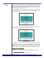
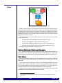
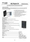
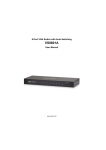
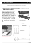
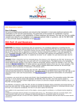
Upstream Port Redundancy and
Failover for System Interconnect
Switches
®
Application Note
AN-572
By Sean Sweeney
Notes
Introduction
Fault tolerance of the system processor is a critical requirement in embedded and storage systems like
the one shown in Figure 1. In this example, if the active processor blade were to fail, then the standby card
would take its place. This is called failover. Failover enables fault tolerance, which can increase overall
system RAS (reliability, availability, and serviceability).
Figure 1 A Fault-Tolerant System with Active and Standby Processors
It is desirable, and in fact common, for failover to happen automatically (via software) without the intervention of a technician. A popular way to achieve this kind of fault tolerance is to use two upstream ports in
the switch. One upstream port is connected to the active processor blade, while the other is connected to
the standby processor blade. During failover, the standby processor becomes the active root complex and
takes over the control and management of the PCI Express® (PCIe®) switch and the I/O blades.
In order to support failover, a switch must implement two features: redundant upstream ports and a
failover mechanism. Note that non-transparent bridging (NTB) functionality is not required for a switch to
support failover. The IDT System Interconnect PCIe Switches are useful in building fault-tolerant systems
because they satisfy both of the requirements. In addition to being fault-tolerant, these systems can achieve
high port densities (up to 16 ports) with full peer-to-peer simultaneous switching between all ports at wire
speed.
This document describes the redundancy and failover features of the IDT System Interconnect PCI
Express Switches1 and also discusses how these switches can be used to build fault-tolerant systems.
Upstream Port Redundancy
The redundancy feature can be enabled during fundamental reset. Pin strapping of the SWMODE
signals is used to turn on redundancy and select which upstream port is active and which is standby. This
section provides an overview of the PES64H16 ports with respect to number and widths, and also
describes the upstream redundancy implementation.
1.
While this application note refers to the PES64H16 device, the information herein applies to any device in the System
Interconnect Switch family.
1 of 4
© 2007 Integrated Device Technology, Inc.
May 24, 2007
IDT
Application Note AN-572
Notes
The PES64H16 has sixteen physical x4 ports. In a 16x4 configuration, there are also sixteen logical
ports, 0 through 15. Even/odd (and not odd/even) x4 ports can be merged to form a x8 port. In such a case,
the two merged physical ports take on the even port number. This rule is valid for all ports, including the
upstream port(s). Port 0 is always an upstream port, regardless of port width. Port 2 is an upstream port if
redundancy is enabled, also regardless of port width.
Figure 2 illustrates a switch configuration using redundant x4 upstream ports 0 and 2. Note that ports 1
and 3 are downstream ports. This configuration has sixteen logical x4 ports: two redundant upstream ports
and fourteen downstream ports.
.
Figure 2 Upstream x4 Ports
Figure 3 illustrates a switch configuration using redundant x8 upstream ports 0 and 2. There are fourteen logical ports: two redundant upstream ports and twelve downstream ports.
Figure 3 Upstream x8 Ports
The SERDES for ports 0 and 2 are connected via a multiplexer. This is an important feature used in
dynamic failover2 mode, wherein certain triggers can cause the multiplexer to switch. This causes the
standby port to become active, that is, to fail over. If the redundancy feature is not enabled, then the
SERDES multiplexer is not active and the dynamic failover feature is not available. Note that this is not a
“hot standby” scheme; the standby processor port must undergo link training before it can become active.
System Considerations
A typical system control topology for implementing failover with the PES64H16 is shown in Figure 4.
2. Dynamic failover
is explained in subsequent sections of this application note.
2 of 4
May 24, 2007
IDT
Application Note AN-572
Notes
Figure 4 Control Topology
Typically, a heartbeat message is sent periodically from the active processor to the standby processor in
order to continuously verify that the active processor is functioning. Due to its ubiquity, ease of implementation, and the fact that it comes for free on root complex chipsets, Ethernet is a natural choice to carry the
heartbeat message. Should the heartbeat message not be received by the standby processor within a
predetermined time frame, the active processor would be considered “down” and the standby processor
would commence the failover operation.
There are signals which are important to failover operation that must connect each processor blade to
the switch blade. They are:
– A fundamental switch reset (PERSTN) signal (required for static failover only)
– Four switch mode (SWMODE) signals (required for static failover only)
– Two Slave SMBus (SSMB) signals (required for dynamic software or timer failover only)
– An upstream port select (USPSEL) signal (required for dynamic hardware failover only)
These signals will be discussed further in subsequent sections.
Failover Methods: Static and Dynamic
Once redundancy is enabled, failover is also supported. The system designer can choose between two
failover methods: static and dynamic. Static failover involves a fundamental reset of the system, while
dynamic failover does not. Details on each of these failover methods are provided in the next two sections.
Static Failover
Static failover is essentially a swapping of the active and standby upstream ports during a fundamental
reset of the system. During fundamental reset, the SWMODE vector is changed to select the other
upstream port.
To be in a mode conducive to static failover, the switch can be operating under SWMODE vectors 0x8,
0x9, 0xA, or 0xB3. To perform a static failover, a processor (usually the standby processor, except in the
case of a planned switchover) would assert fundamental reset (PERSTN) to the switch, toggle to the
complementary upstream port using the appropriate SWMODE vector, then deassert reset.
Because static failover requires a fundamental reset of the system, the dynamic failover method might
be preferred since it does not require a fundamental reset of the switch.
3. Other modes could be relevant in certain cases, but are of limited use as they do not support toggling between upstream
ports (“re-failover”).
3 of 4
May 24, 2007
IDT
Application Note AN-572
Notes
Dynamic Failover
Dynamic failover makes use of the SERDES multiplexing mentioned previously, as well as three triggers
which can initiate the switching of the SERDES to the other upstream port. This operation requires a hot
reset, during which all of the switch ports are retrained. A configuration option exists whereby the downstream ports’ states are preserved during hot reset. If this option is enabled, the new upstream port will be
trained, but the downstream ports and core switch logic will not be reset. This feature is disabled by default
and can be enabled in the Switch Control (SWCTL) register.
As with static switchover, upstream port redundancy must be selected during fundamental reset. It can
be enabled as part of the boot mode configuration by selecting an appropriate SWMODE vector with redundant upstream ports. Either port 0 or port 2 can be configured to be the upstream port. By implication, the
other port would become the standby port. Once redundancy is enabled, dynamic failover is also enabled.
This is reflected in the Upstream Port Failover Status (USPFSTS) register.
Dynamic Failover Triggers
The failover operation is triggered in one of three ways.
◆
Software-Initiated Failover
An upstream port failover can be initiated via the Upstream Port Failover Control (USPFCTL)
register. A software initiated failover can be sourced by the upstream port (as in the case of a
planned switchover) or the slave SMBus.
Start with the upstream port value in the USPFCTL register corresponding to the active upstream
port. To trigger failover, write the USPFCTL register with the new upstream port value.
◆
Hardware Pin-Initiated Failover
An upstream port failover may be initiated by a change in the state of the Upstream Port Select
(USPSEL) signal pin. This failover mode must be enabled in the USPFCTL register and the
upstream port selected by the USPSEL signal must differ from the current upstream port.
The USPSEL signal should initially correspond to the active upstream port. Enable hardware-based
failover in the USPFCTL register. To initiate failover, change the state of the USPSEL signal.
◆
Watchdog Timer-Initiated Failover
An upstream port failover may be initiated as the result of an expiration of a watchdog timer. Such a
failover must be enabled in the USPFCTL register. If software does not reset the timer, thereby
allowing the Watchdog Timer Count (COUNT) field in the Upstream Port Failover Watchdog Timer
(USPFTIMER) register to transition from a one to a zero, then failover will occur. The timer can be
written via the slave SMBus or the upstream port.
The upstream port value in the USPFCTL register should initially correspond to the active upstream
port. Enable timer-based failover in the USPFCTL register and set the timer in the USPFTIMER
register to the desired value. Failover is initiated if software does not reset the timer before it
reaches zero.
After a failover has occurred, the switch will be in a state wherein another failover can be performed.
Simply supply another trigger to perform another failover.
Summary
The IDT System Interconnect PCI Express Switches are ideal for building fault-tolerant, high-RAS
embedded and storage systems. Their key advantages are the ability to support failover, the highest port
densities in the industry, and wire speed, simultaneous switching between any and all ports.
References
PES64H16 User Manual
Revision History
May 24, 2007: Initial publication.
4 of 4
May 24, 2007