1
PACiS SCE
System Configuration Editor
SCE/EN O/C40
Version
4.5
Operation Guide
Operation Guide
Contents
PACiS System Configuration Editor
SCE/EN O/C40
Page 1/2
PACiS SCE
OPERATION GUIDE
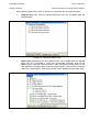
CONTENTS
Safety & Handling
Introduction
SCE/EN SA/C40
SCE/EN IT/C40
Technical Data
SCE/EN TD/C40
Functional Description
SCE/EN FT/C40
Human Machine Interface
SCE/EN HI/C40
Application
SCE/EN AP/C40
Lexical
SCE/EN LX/C40
SCE/EN O/C40
Page 2/2
Operation Guide
Contents
PACiS System Configuration Editor
BLANK PAGE
Safety & Handling
SCE/EN SA/C40
PACiS System Configuration Editor
SAFETY & HANDLING
Safety & Handling
SCE/EN SA/C40
PACiS System Configuration Editor
Page 1/8
CONTENT
1.
INTRODUCTION
3
2.
SAFETY
4
2.1
Health and Safety
4
2.2
Explanation of symbols and labels
4
2.3
Installing, Commissioning and Servicing
4
2.4
Decommissioning and Disposal
4
3.
GUARANTIES
5
4.
COPYRIGHTS & TRADEMARKS
6
4.1
Copyrights
6
4.2
Trademarks
6
5.
WARNINGS REGARDING USE OF SCHNEIDER ELECTRIC
PRODUCTS
7
SCE/EN SA/C40
Page 2/8
Safety & Handling
PACiS System Configuration Editor
BLANK PAGE
Safety & Handling
PACiS System Configuration Editor
1.
SCE/EN SA/C40
Page 3/8
INTRODUCTION
This document is a chapter of PACiS System Configuration Editor PACiS SCE V4.5
documentation binder. It describes the safety, handling, packing and unpacking procedures
applicable to PACiS SCE software tools.
SCE/EN SA/C40
Safety & Handling
Page 4/8
2.
SAFETY
WARNING:
2.1
PACiS System Configuration Editor
THIS SAFETY SECTION SHOULD BE READ BEFORE COMMENCING
ANY WORK ON THE EQUIPMENT.
Health and Safety
The information in the Safety Section of the product documentation is intended to ensure
that products are properly installed and handled in order to maintain them in a safe condition.
It is assumed that everyone who will be associated with the equipment will be familiar with
the contents of the Safety Section and all Safety documents related to the PC and
Communication networks.
2.2
Explanation of symbols and labels
The meaning of symbols and labels may be used on the equipment or in the product
documentation, is given below.
2.3
Installing, Commissioning and Servicing
Equipment operating conditions
The equipments (PC supporting PACiS SCE) should be operated within the specified
electrical and environmental limits.
Fibre optic communication
Optical LED transceivers used in Switch boards are classified as IEC 825-1 Accessible
Emission Limit (AEL) Class 1 and consequently considered eye safe.
Optical power meters should be used to determine the operation or signal level of the device.
2.4
Decommissioning and Disposal
Disposal:
It is recommended to avoid incineration and disposal of the PACiS SCE CD-ROM. The
product should be disposed of in a safe manner.
Safety & Handling
PACiS System Configuration Editor
3.
SCE/EN SA/C40
Page 5/8
GUARANTIES
The media on which you received Schneider Electric software are warranted not to fail
executing programming instructions, due to defects in materials and workmanship, for a
period of 90 days from date of shipment, as evidenced by receipts or other documentation.
Schneider Electric will, at its option, repair or replace software media that do net execute
programming instructions if Schneider Electric receive notice of such defects during the
guaranty period. Schneider Electric does not guaranty that the operation of the software shall
be uninterrupted or error free.
A Return Material Authorisation (RMA) number must be obtained from the factory and clearly
marked on the package before any equipment acceptance for guaranty work.
Schneider Electric will pay the shipping costs of returning to the owner parts, which are
covered by warranty.
Schneider Electric believe that the information in this document is accurate. The document
has been carefully reviewed for technical accuracy. In the event that technical or
typographical errors exist, Schneider Electric reserves the right to make changes to
subsequent editions of this document without prior notice to holders of this edition. The
reader should consult Schneider Electric if errors are suspected. In no event shall
Schneider Electric be liable for any damages arising out of or related to this document or the
information contained in it.
Expect as specified herein, Schneider Electric makes no guaranties, express or implied and
specifically disclaims and guaranties of merchantability or fitness for a particular purpose.
Customer's rights to recover damages caused by fault or negligence on the part
Schneider Electric shall be limited to the amount therefore paid by the customer.
Schneider Electric will not be liable for damages resulting from loss of data, profits, use of
products or incidental or consequential damages even if advised of the possibility thereof.
This limitation of the liability of Schneider Electric will apply regardless of the form of action,
whether in contract or tort, including negligence. Any action against Schneider Electric must
be brought within one year after the cause of action accrues. Schneider Electric shall not be
liable for any delay in performance due to causes beyond its reasonable control.
The warranty provided herein dues net cover damages, defects, malfunctions, or service
failures caused by owner's failure to follow the Schneider Electric installation, operation, or
maintenance instructions; owner's modification of the product; owner's abuse, misuse, or
negligent acts; and power failure or surges, fire, flood, accident, actions of third parties, or
other events outside reasonable control.
SCE/EN SA/C40
Page 6/8
4.
COPYRIGHTS & TRADEMARKS
4.1
Copyrights
Safety & Handling
PACiS System Configuration Editor
Under the copyright laws, this publication may not be reproduced or transmitted in any form,
electronic or mechanical, including photocopying, recording, storing in an information
retrieval system, or translating, in whole or in part, without the prior written consent of
Schneider Electric.
4.2
Trademarks
PACiS, PACiS SCE, PACiS ES, PACiS SCE, PACiS PS, PACiS SCE, are trademarks of
Schneider Electric. Product and company names mentioned herein are trademarks or trade
names of their respective companies.
Safety & Handling
PACiS System Configuration Editor
5.
SCE/EN SA/C40
Page 7/8
WARNINGS REGARDING USE OF SCHNEIDER ELECTRIC PRODUCTS
Schneider Electric products are not designed with components and testing for a level of
reliability suitable for use in or in connection with surgical implants or as critical components
in any life support systems whose failure to perform can reasonably be expected to cause
significant injuries to a human.
In any application, including the above reliability of operation of the software products can be
impaired by adverse factors, including -but not limited- to fluctuations in electrical power
supply, computer hardware malfunctions, computer operating system, software fitness,
fitness of compilers and development software used to develop an application, installation
errors, software and hardware compatibility problems, malfunctions or failures of electronic
monitoring or control devices, transient failures of electronic systems (hardware and/or
software), unanticipated uses or misuses, or errors from the user or applications designer
(adverse factors such as these are collectively termed "System failures").
Any application where a system failure would create a risk of harm to property or persons
(including the risk of bodily injuries and death) should not be reliant solely upon one form of
electronic system due to the risk of system failure to avoid damage, injury or death, the user
or application designer must take reasonably steps to protect against system failure,
including -but not limited- to back-up or shut-down mechanisms, not because end-user
system is customised and differs from Schneider Electric testing platforms but also a user or
application designer may use Schneider Electric products in combination with other
products.
These actions cannot be evaluated or contemplated by Schneider Electric; Thus, the user or
application designer is ultimately responsible for verifying and validating the suitability of
Schneider Electric products whenever they are incorporated in a system or application, even
without limitation of the appropriate design, process and safety levels of such system or
application.
SCE/EN SA/C40
Page 8/8
Safety & Handling
PACiS System Configuration Editor
BLANK PAGE
Introduction
SCE/EN IT/C40
PACiS System Configuration Editor
INTRODUCTION
Introduction
PACiS System Configuration Editor
SCE/EN IT/C40
Page 1/6
CONTENT
1.
INTRODUCTION TO PACiS
3
2.
INTRODUCTION TO PACiS GUIDES
4
2.1
Chapters description
4
2.1.1
Chapter Safety (SA)
4
2.1.2
Chapter Introduction (IT)
4
2.1.3
Chapter Technical Data (TD)
4
2.1.4
Chapter HMI, Local control and user interface (HI)
4
2.1.5
Chapter Installation (IN)
4
2.1.6
Chapter Settings (ST)
4
2.1.7
Chapter Lexical (LX)
4
2.2
Operation guide
5
2.3
Technical guide
5
3.
INTRODUCTION TO PACiS SCE APPLICATIONS
6
SCE/EN IT/C40
Page 2/6
Introduction
PACiS System Configuration Editor
BLANK PAGE
Introduction
SCE/EN IT/C40
PACiS System Configuration Editor
1.
Page 3/6
INTRODUCTION TO PACiS
The PACiS range will continue to be expanded. The general features of PACiS will also be
enhanced, as we are able to adopt new technology solutions.
For
up-to-date
information
www.schneider-electric.com
on
any
PACiS
product,
visit
our
website:
SCE/EN IT/C40
Page 4/6
2.
Introduction
PACiS System Configuration Editor
INTRODUCTION TO PACiS GUIDES
This version of the PACiS SCE documentation refers to version PACiS V4.5. The guides
provide a functional and technical description of the PACiS System Configuration Editor PACiS SCE adapted to PACiS V4 (IEC61850 Station Bus) and a comprehensive set of
instructions for the PACiS SCE’s use and application.
PACiS SCE guides is divided into two volumes, as follows:
•
Operation Guide: includes information on the application of the PACiS SCE and a
technical description of its features. It is mainly intended for protection & control
engineers concerned with the selection and application of the PACiS SCE for the
Configuration of PACiS solution or of any of the PACiS equipment.
•
Technical Guide: contains information on the installation and commissioning of the
PACiS SCE, and also a section on fault finding. This volume is intended for site
engineers who are responsible for the installation, commissioning and maintenance of
the PACiS SCE application.
2.1
Chapters description
2.1.1
Chapter Safety (SA)
This chapter contains the safety instructions, handling and reception of electronic equipment,
packing and unpacking parts, Copyrights and Trademarks.
2.1.2
Chapter Introduction (IT)
This is this document containing the description of each chapter of the PACiS SCE guides. It
is a brief introduction to PACiS SCE capabilities.
2.1.3
Chapter Functional Description (FT)
This chapter contains a description of the product. It describes the functions included in
PACiS SCE.
2.1.4
Chapter Technical Data (TD)
This chapter contains the technical data including, accuracy limits, recommended operating
conditions, ratings and performance data.
It also describes environment specification, compliance with technical standards.
2.1.5
Chapter HMI, Local control and user interface (HI)
This chapter contains the operator interface description, Menu tree organisation and
navigation, Setting/configuration software.
2.1.6
Chapter Installation (IN)
This chapter contains the installation procedures.
2.1.7
Chapter Commissioning record sheet (RS)
This chapter provides detailed record sheets to commission PACiS SCE.
2.1.8
Chapter Settings (ST)
This chapter contains the list of the setting with defaults values and range of the PACiS SCE.
2.1.9
Chapter Maintenance, Fault finding, Repairs (MF)
This chapter provides advice on how to identify failure modes, fault codes and describes the
recommended repair actions.
Introduction
PACiS System Configuration Editor
2.1.10
SCE/EN IT/C40
Page 5/6
Chapter Problem analysis (PR)
This chapter provides practical examples of problem solving and company contact
information. It includes all information on the self-checking features and diagnostics of
PACiS SCE.
2.1.11
Chapter Lexical (LX)
This chapter contains lexical description of acronyms and definitions of the PACiS SCE.
2.2
Operation guide
This binder contains the following chapters:
SA, IT, TD, FT, HI, AP, LX
2.3
Technical guide
This binder contains the following chapters:
SA, IT, TD, FT, IN, ST, RS, MF, PR, LX
SCE/EN IT/C40
Page 6/6
3.
Introduction
PACiS System Configuration Editor
INTRODUCTION TO PACiS SCE APPLICATIONS
The PACiS SCE Applications are mainly defined in the Application chapter (AP) of each
PACiS equipment (MiCOM C264/C264P, PACiS GTW, PACiS OI).
Technical Data
SCE/EN TD/C40
PACiS System Configuration Editor
TECHNICAL DATA
Technical Data
PACiS System Configuration Editor
SCE/EN TD/C40
Page 1/6
CONTENT
1.
SCOPE OF THE DOCUMENT
3
2.
REQUIREMENTS
4
3.
CAPABILITIES
5
SCE/EN TD/C40
Page 2/6
Technical Data
PACiS System Configuration Editor
BLANK PAGE
Technical Data
PACiS System Configuration Editor
1.
SCE/EN TD/C40
Page 3/6
SCOPE OF THE DOCUMENT
This document is a chapter of PACiS System Configuration Editor PACiS SCE V4.5
documentation binder. It describes the Technical Data (SCE/EN TD) of this set of software
applications.
SCE/EN TD/C40
Technical Data
Page 4/6
2.
PACiS System Configuration Editor
REQUIREMENTS
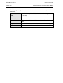
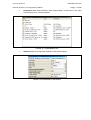
The following tables give the minimum hardware requirements to run correctly PACiS SCE
application.
Type of PC
Standard desktop with CPU Centrino Duo 1.7GHz or upper
RAM
1 GB RAM
Hard Disk
80 GB - FT32 format
CD-ROM Reader
Operating System
Windows 2000 Professional SP4, 2000 Server SP2 or Windows XP
SP2
Graphical
VGA screen 256 colours minimum, resolution 1024*768 or upper
Optionally
Ethernet port, CD-Writer for database exchange
Technical Data
PACiS System Configuration Editor
3.
SCE/EN TD/C40
Page 5/6
CAPABILITIES
The capabilities of PACiS SCE application allows to define the maximal configuration of a
PACiS project. The cardinality limits of the different components of a PACiS project are
described in the chapter PACiS SCE/EN MF § 2.2.
SCE/EN TD/C40
Page 6/6
Technical Data
PACiS System Configuration Editor
BLANK PAGE
Functional Description
SCE/EN FT/C40
PACiS System Configuration Editor
FUNCTIONAL DESCRIPTION
Functional Description
PACiS System Configuration Editor
SCE/EN FT/C40
Page 1/10
CONTENT
1.
SCOPE OF THE DOCUMENT
3
2.
PACiS SCE ARCHITECTURE
4
2.1
General Description
4
2.2
Functional Specification
4
2.2.1
PACiS SCE Users
5
2.2.2
PACiS SCE Template & Object
5
2.2.3
Database creation process
6
2.2.4
Version & release
7
2.3
External Interfaces
7
2.4
Human Interface
8
2.4.1
PACiS SCE General Display
8
2.4.2
Working or Docking Window
10
2.4.3
Management under Windows 2000 & XP
10
SCE/EN FT/C40
Page 2/10
Functional Description
PACiS System Configuration Editor
BLANK PAGE
Functional Description
PACiS System Configuration Editor
1.
SCE/EN FT/C40
Page 3/10
SCOPE OF THE DOCUMENT
This document is a chapter of PACiS SCE V4.5 documentation binders. It is the functional
description of PACiS System Configuration Editor software application dedicated to the
PACiS system and sub-systems.
SCE/EN FT/C40
Page 4/10
Functional Description
PACiS System Configuration Editor
2.
PACiS SCE ARCHITECTURE
2.1
General Description
The System Configuration Editor (PACIS SCE) is the central tool in charge to manage the
PACiS system database for the PACiS equipment. The system configuration database
contains the configuration data for the PACiS system equipment:
•
PACiS OI the Operator Interface
•
PACiS SMT the System Management Tool that download Databases
•
PACiS GTW the Tele control gateway
•
MiCOM Computers C264 & C264P
•
PACiS ES the Equipment Simulator
The PACIS SCE allows some authorised personnel to interact with the PACiS system
configuration:
•
modelling of coherent system configuration data: devices, electrical topologies,
graphical mimics, automations
•
generation of configuration data-file for IEC61850 devices of the PACiS project
To generate any equipment database, the PACIS SCE manages:
•
Inner data of the device itself (structure and parameters values)
•
Exchange data of the device with other system devices
•
Exchange data of the device with non-system devices
With the 3rd case, the PACIS SCE manages the communication with all non-PACiS devices
with typically IED or protection devices on Legacy BUS or system network. It is only by the
configuration of communication mapping that PACIS SCE can handle non-PACiS devices.
2.2
Functional Specification
PACiS System Configuration Editor is a tool that:
•
helps in definition/edition of equipment data with specific editors (attribute, mimic,
ISaGRAF) or with queries on configuration
•
generates equipment databases
The definition of data is done firstly by the definition by developer experts of templates or
models of data. These templates are then stored and delivered in PACIS SCE libraries. In a
second time, the models can be loaded and instanced as a clever kind of duplication to
create object data customised to the application case.
When all data of the concrete case are defined, the PACIS SCE generates a coherent set of
databases that can be loaded into each system equipment.
Functional Description
SCE/EN FT/C40
PACiS System Configuration Editor
2.2.1
Page 5/10
PACIS SCE Users
Control access of an operator is realised through a login and password capture.
Different levels of operators are distinguished depending on its role:
•
Level 1 allows the modification of an existing configuration by adjustment of
parameters, settings or graphical representations. The users of level 1 can also add or
remove elements derived from the user template libraries. They can generate PACiS
application databags. Level 1 users are typically final users.
•
Level 2 allows the modification of an existing configuration by adding or removing
elements derived from the user templates libraries. They can break the links between
the templates and the instantiated objects. Like level 1 users they can generate PACiS
application databags. Level 2 users are Integrators and VARs.
•
Level 3 users have the capability to modify and create new templates derived from the
existing template libraries. They can generate PACiS application databags but also
template libraries. User of level 3 will be all T&D-EAI PACiS specialists.
•
Level 4 users are PACiS SCE experts. They can modify and create the templates
directly from the structural database elements. Their PACIS SCE user level allows
also the management of all template databases and the administration of the
structural database. The level 4 users are the PACiS SCE administrators.
Such categories is only an outline of PACIS SCE users since several of its tools thanks to
specific editors, or report managers, can provided the records needed by other tasks:
commissioning cubicle, mapping extraction, etc.
2.2.2
PACIS SCE Template & Object
A database is basically a collection of persistent data. In the PACIS SCE framework, a
database is a collection of objects. Any object has its specific attributes, organised in
categories and subcategories. The objects are organised in the database by following predefined association rules.
The structural database defines object types and association types. Association types
are hierarchical link types and relation link types between object types. Hierarchical links
are defined for father/child associations. Relation links are defined for other associations,
and may hold attributes. Cardinalities are defined for all associations.
A library database contains templates. A template is a collection of objects/associations
instantiated from the structural database or from others templates.
A configuration database contains objects/associations instantiated from types of the
structural database or from templates. It also contains its own templates, created specifically
for the configuration, or imported from a library database. A configuration database defines
all data needed by system devices to feel up customer application.
All the database elements support internationalisation (multiple languages).
SCE/EN FT/C40
Functional Description
Page 6/10
2.2.3
PACiS System Configuration Editor
Database creation process
To create the database downloaded to system devices, the common way is to:
•
Import a template from an external library into current database (in its template area)
•
Customise the template if needed in DB template area
•
Instantiated the template from template to Object part of the database
•
Feel up predefined attribute known as degree of freedom (for example the name)
•
Generate devices databases
The link between template and instantiated object can be kept. Nevertheless this relation can
be broken for deep object modifications.
During all this creation process, the PACIS SCE make control in data coherency with its
Data Model. The checks are made with templates and objects. The checks are mare during
configuration edition and/or by a check action. They are done on:
•
Attribute input
•
Relation creation
•
Generation
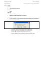
Configuration database
Library = Collection of Models
Local templates
Configuration Objects =
Configuration
Instance 1
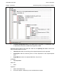
Import
Template
Instance 2
Instance n
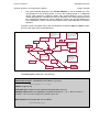
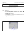
S0126ENa
FIGURE 1: CONFIGURATION PROCESS
Functional Description
SCE/EN FT/C40
PACiS System Configuration Editor
2.2.4
Page 7/10
Version & release
Along time, system’s device features have evolution and their inner data base structure is
subject to modification. PACiS SCE need to feel the new requirement and has also
evolutions and corrections referenced by version.
A unique reference determines the coherent set of system equipment database and
soft/hard equipment that PACIS SCE can be used.
PACIS SCE can be compared two referenced versions of a configuration.
2.3
External Interfaces
PACiS
Data Model
Interface
files
External tools
Xml files
CMT
MiCOM
C264
SMT
OI
ISaGRAF
full integrated
workbenches
SCE
System
databag
FBD
Ga teway
Equipment
Simulator
Configuration
S0469ENa
FIGURE 2: EXTERNAL INTERFACES
There is no software interfaces between PACIS SCE and other external tools or PACiS
devices.
External interfaces are implemented throw files:
•
Xml files: the user can export or import a whole configuration or only a subset. A
PACIS SCE exchange Xml format is defined for describing files which are:
•
exported from PACIS SCE to an external tool.
•
imported from an external tool to PACIS SCE.
•
System databag: from a referenced version of a configuration, PACIS SCE generates
an application databag for each PACiS devices. The application databags are bagged
in a System databag. The system databag are used by PACiS SMT to download
application databag in each PACiS devices. This system databag could be used by
PACiS simulator tools.
•
Reports: the user selects a whole configuration or only a subset and asks a report. A
predefined report pdf format is delivered with PACIS SCE.
SCE/EN FT/C40
Functional Description
Page 8/10
PACiS System Configuration Editor
2.4
Human Interface
2.4.1
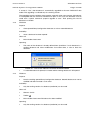
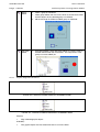
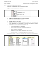
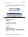
PACIS SCE General Display
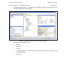
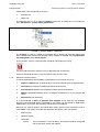
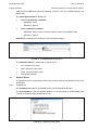
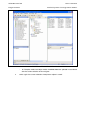
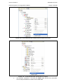
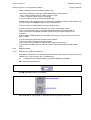
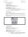
At initial start-up or after installation of new version, the PACIS SCE application display can
be seen as represented below (as far as user has all PACIS SCE rights and licences). It
should be noticed that all parts are not necessary needed for all kind of user.
FIGURE 3: PACIS SCE DISPLAY AT START-UP
The staring view is empty. Explanation of each area is given below with some information on
it.
Functional Description
PACiS System Configuration Editor
SCE/EN FT/C40
Page 9/10
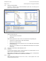
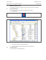
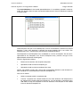
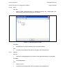
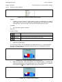
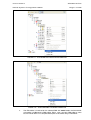
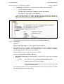
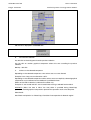
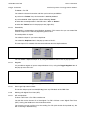
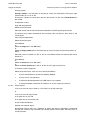
For displaying information it is needed to load a database. After such database load, the
PACIS SCE application looks as below.
FIGURE 4: PACIS SCE DISPLAY WITH LOADED DATABASE
The display is composed of 5 areas:
•
Title Bar
•
Menu Bar
•
Tool Bar
•
Docking Window or common work area composed of several on line optional and
customisable areas.
•
State Bar
SCE/EN FT/C40
Functional Description
Page 10/10
2.4.2
PACiS System Configuration Editor
Working or Docking Window
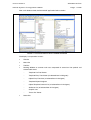
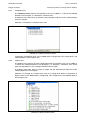
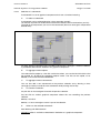
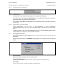
By default or selecting all items in Menu Bar/Windows option items, the working area is
displayed with all areas as below:
FIGURE 5: DOCKING WINDOW
Areas are viewers driven by:
•
Navigator perspective Tree Viewer
•
Mimic Editor
When selecting object (click, enter) all views are “refreshed” with corresponding data:
•
Components List (Object/relations under selected object)
•
Attributes List (of object selected)
•
Template Entry List (of existing template of that can be added under selected object
from DB template list)
•
Object Entry List (of objects that can be added under selected object from conceptual
modelisation)
2.4.3
Management under Windows 2000, 2000 Server & XP
2.4.3.1
Windowing
The PACIS SCE Application follows windowing behaviour. As presented before it has all
option for iconify, maximise/minimise, or close/exit.
When window is minimised it can be resized by its border or corner, and displaced by
dragging of title bar. This behaviour is also down with sub windows.
2.4.3.2
ToolTip
When mouse pointer remains on tool bar icon or menu, a tool tip appears with a short
message explaining the function.
User Interface
SCE/EN HI/C40
PACiS System Configuration Editor
USER INTERFACE
User Interface
PACiS System Configuration Editor
SCE/EN HI/C40
Page 1/208
CONTENT
1.
SCOPE OF THE DOCUMENT
5
1.1
Using PACiS SCE
5
1.1.1
PACiS SCE Users
6
1.1.2
Devices handle by PACiS SCE
6
1.1.3
PACiS SCE Components
6
1.1.4
PACiS SCE Data hierarchy
7
1.1.5
PACiS SCE Template & Object
7
1.1.6
Database creation process
8
2.
GENERAL DESCRIPTION
9
2.1
Launching PACiS SCE
9
2.2
Leaving PACiS SCE
9
2.3
PACiS SCE General Display
10
2.3.1
Title Bar
12
2.3.2
Menu Bar
12
2.3.3
Tool bars
13
2.3.4
Working or Docking Window
13
2.3.5
Status Bar
18
2.4
Management under Windows 2000 & XP
18
2.4.1
Windowing
18
2.4.2
ToolTip
18
3.
PACiS SCE DETAILED WINDOWS DESCRIPTION
19
3.1
Tools Bar
19
3.1.1
Common Tools
19
3.1.2
OI Mimic Tools
20
3.1.3
Computer Mimic Tools
21
3.2
Docking Window
22
3.2.1
Docking Window Management
22
3.2.2
Selecting displayed area in working window
22
3.2.3
Moving/placing areas into working window area
23
3.3
Navigator
24
3.4
Components List
26
3.5
Attributes List Editor of Object/Template
27
3.6
Database Entries
28
3.6.1
Templates list
28
3.6.2
Templates entry
30
3.6.3
Objects entry
30
3.7
Graphic Area
31
SCE/EN HI/C40
Page 2/208
User Interface
PACiS System Configuration Editor
4.
PACiS SCE MENU COMMAND
32
4.1
File Menu
32
4.1.1
File/New…
34
4.1.2
File/Open…
35
4.1.3
File/Close
37
4.1.4
File/Save
37
4.1.5
File/Prepare upgrade & Save
38
4.1.6
File/Clean & Save
38
4.1.7
File/Create a copy
39
4.1.8
File/Check in…
40
4.1.9
File/Check out
42
4.1.10
File/Check
43
4.1.11
File/Generate…
44
4.1.12
File/Properties
47
4.1.13
File/Exit
48
4.2
Edit Menu
49
4.2.1
Edit/Cut
50
4.2.2
Edit/Copy
51
4.2.3
Edit/Paste
54
4.2.4
Edit/Delete
54
4.2.5
Edit/Select all
55
4.2.6
Edit/Edit relations
56
4.2.7
Edit/Reach
58
4.2.8
Edit/Search…
59
4.2.9
Edit/Switch Mode
63
4.2.10
Move
65
4.2.11
Replace
65
4.2.12
Add
66
4.2.13
Duplicate
68
4.2.14
Canonic Form
69
4.2.15
Break All Inner Template Link
70
4.2.16
Break Upper Template Link
72
4.2.17
View Linked Attributes
73
4.2.18
View Template Instances
75
4.2.19
View Template Content
76
4.2.20
Create Backup
77
4.2.21
New
79
4.2.22
Define
82
4.2.23
Associate Parameter
85
4.2.24
DOF Status
87
4.2.25
SBus Automatic Addressing
89
User Interface
PACiS System Configuration Editor
SCE/EN HI/C40
Page 3/208
4.2.26
Unused templates
90
4.2.27
Unused templates refresh
91
4.3
User Menu
92
4.3.1
User/Login
92
4.3.2
User/Administration
93
4.4
Graphic Menu
95
4.4.1
Graphic palettes
96
4.4.2
OI mimic
109
4.4.3
Computer mimic
121
4.4.4
Graphic/Utility sub-menu
127
4.5
Workbenches Menu
128
4.5.1
Workbenches/ISaGRAF Edit …
128
4.5.2
Workbenches/ISaGRAF Compile
130
4.5.3
Workbenches/FBD Edit …
130
4.6
Tools Menu
132
4.6.1
Tools/Options
133
4.6.2
Tools/Create Template…
134
4.6.3
Tools/Search all…
135
4.6.4
Tools/Export, Import sub-menu
136
4.6.5
Tools/Report…
144
4.6.6
Tools/Export FBD
145
4.6.7
Tools/Import FBD
152
4.6.8
Tools/Export IOMapping…
155
4.6.9
Tools/Export Wiring
158
4.6.10
Tools/Export SCADA
159
4.6.11
Tools/Export IEC61850 SCL
160
4.6.12
Tools/Import IEC61850 SCD…
163
4.6.13
Tools/Manage IEC61850 IED…
165
4.6.14
Tools/Languages…
168
4.6.15
Tools/Dictionary…
170
4.7
Window
172
5.
TRACES WINDOW
5.1
Trace saving
174
5.2
Trace log file checking
176
6.
FBD EDITOR
6.1
Generalities of FBD
177
6.2
The FBD Editor Views
178
6.2.1
FBD Editor View
178
6.2.2
The FBD Overview
179
6.2.3
Toolbar
180
6.2.4
Library Toolbar
180
173
177
SCE/EN HI/C40
Page 4/208
User Interface
PACiS System Configuration Editor
6.2.5
Logging View
181
6.2.6
Key Functions
181
6.3
Understanding FBD
182
6.3.1
Graphical component on the Editor View
182
6.3.2
Language Elements
183
6.3.3
Text Annotations
186
6.3.4
Evaluation strategy
186
6.4
Working with the Equation Viewer
186
6.4.1
FBD document
186
6.4.2
Navigation Features
187
6.4.3
Zoom Features
188
6.4.4
Selection Model
189
6.4.5
Working with Functions and Function Blocks
192
6.4.6
Working with Signal Flow Lines (SFL)
194
6.4.7
Working with Slots
197
6.4.8
Working with FBD Network
198
6.4.9
FBD Graphical Controls
201
6.4.10
FBD Semantical Controls
202
6.4.11
Working with Literals
202
6.4.12
Working with Text Annotations
205
6.5
Printing FBD Documents
205
6.6
Popup Activity Lists
206
6.6.1
Activity List of the Editor View
206
6.6.2
Activity List of Blocks
206
6.6.3
Activity List of Slots
206
6.6.4
Activity List of Connecting Lines
207
6.6.5
Activity List of Signal Flow Lines
207
6.6.6
Activity List of H/V Connections
207
6.6.7
Activity List of Text Annotations
207
6.6.8
Activity List of the Logging View
208
User Interface
SCE/EN HI/C40
PACiS System Configuration Editor
1.
Page 5/208
SCOPE OF THE DOCUMENT
This document is a chapter PACiS SCE (System Configuration Editor) documentation
binder. It describes all User Interface or Human Machine Interface of this engineering tool.
1.1
Using PACiS SCE
PACiS System Configuration Editor is a tool that:
•
Helps in definition/edition of all system data with its equipment.
•
Generates each PACiS equipment databases.
At first, the data definition is done by experts through templates or models of data. These
templates are then stored and delivered in PACiS SCE libraries.
In a second time, the models can be loaded and instantiated as a clever kind of duplication
to create object data customised to the application case.
In a third time users can makes modification on its object database.
When all data of the concrete case are defined, the PACiS SCE generates a coherent set of
databases, named system databag, which can be loaded into each system equipment by
PACiS SMT, the PACiS maintenance tools.
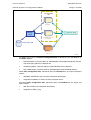
PACiS SCE can export/import XML files to/from external tools and generate reports.
PACiS
Data Model
Interface
files
External tools
Xml files
CMT
MiCOM
C264
SMT
OI
ISaGRAF
full integrated
workbenches
CIS SCE
System
databag
FBD
Gateway
Equipment
Simulator
Template
libraries
Configuration
S0478ENa
FIGURE 1 - PACiS SCE DATA FLOW
SCE/EN HI/C40
Page 6/208
1.1.1
User Interface
PACiS System Configuration Editor
PACiS SCE Users
This brief definition of PACiS SCE using shows several kind of user:
•
Expert template developers who maintain a set of libraries adapted to specified
equipment, a protocol mapping, a graphical representation, or an electric
automation…
•
Prototypes engineers who should build quickly the draft of a specific substation with
its devices, its main functionality and graphic views, in order to evaluate
implementation solutions.
•
Configuration engineers, who customise, detail and update all structured data of a
specified application case, and generate the databases downloaded to the system
devices.
•
Maintenance technicians who need to modify or adjust parameters prior of new
database download.
Such categories is only an outline of PACiS SCE users since several of its tools thanks to
specific editors, or report managers, can provide the records needed by other tasks:
commissioning cubicle, mapping extraction, …
Because of these different users, PACiS SCE has several “levels” in its HMI interface. This
manual describes all of them whatever could be option or license limitations.
The projection of these user categories on PACiS SCE is not implemented in PACiS V4.
1.1.2
Devices handle by PACiS SCE
PACiS is designed to generate database for PACiS devices:
•
PACiS OI the Operator Interface
•
PACiS SMT the System Management Tool that downloads Databases
•
PACiS ES the Equipment Simulator
•
PACiS GTW the separate Gateway or Tele control Interface to SCADA
•
MiCOM C264 and C264P
To generate any equipment database, the PACiS SCE manages:
•
Inner data of the device itself (structure and parameters values)
•
Exchange data of the device with other system devices
•
Exchange data of the device with non system devices
With the 3rd case, the PACiS SCE manages the communication with all non-PACiS devices
with typically IED or protection devices on Legacy BUS or system network bus. It is only by
the configuration of communication mapping that PACiS SCE can handle non-PACiS
devices. Anyway, the PACiS SCE does not generate database or setting for these nonPACiS devices.
1.1.3
PACiS SCE Components
As most configuration tools, the PACiS SCE is composed of two main software parts with:
•
HMI (Human Machine Interface) of PACiS SCE and associate tools
•
Data Model that includes association rules attributes range, and generators.
The aim of this part is the description of Human Machine interfaces. For a full description of
the data model and its use, refer to chapters Application of each PACiS device.
Nevertheless, a good understanding of the user interface needs at least the few notions
expressed below.
User Interface
SCE/EN HI/C40
PACiS System Configuration Editor
1.1.4
Page 7/208
PACiS SCE Data hierarchy
First of all, Data Model defines structure and structured data. Any piece of information
belongs to a hierarchy of information often referenced from browsing point of view as a
tree. This abstraction of data is named object.
In PACiS SCE all data belong to only one of the three following tree structures:
•
Electric process.
•
System (device characteristics and communication).
•
Graphic definition of Operator Interface with Archives, Graphic, Printing…
FIGURE 2: PACIS SCE DATA HIERARCHY
In the other hand, the piece of information is structured data, with list of attributes. For
example, C264 object has a set of configurable attributes like TCP/IP address or network
name.
FIGURE 3: ATTRIBUTES OF A C264
1.1.5
PACiS SCE Template & Object
All data are defined in data model structure. In PACiS SCE, this notion is fully exploited with
the possibility for a user to create models called templates. Models are duplicated and
modified for concrete cases called Object database. This last one is used to generate all
PACiS devices databags.
SCE/EN HI/C40
User Interface
Page 8/208
PACiS System Configuration Editor
PACiS SCE is then composed of two parts:
•
template part,
•
object part.
The template part is a list of separate models used or not. A model has its own hierarchy
data, with process, system and/or graphic data.
FIGURE 4 - OBJECT MODEL / TEMPLATE
The template is used as a model to create new data in object part. The data which come
from a template are linked to this template. When template is modified, these modifications
are propagated to all its linked objects.
At any moment, user can switch between Template and Object parts using
Current mode Template or Object is always displayed (right of state Bar).
Access to Template functions is only possible for Level 3 and 4 users.
1.1.6
Database creation process
To create the database downloaded to system devices, the common way is to:
1.
Import a template from an external library into current database (in its template area)
2.
Customise the template if needed in database template area
3.
Instantiated the template from template to Object part of the database
4.
Modify predefined attribute(s) known as degree of freedom (D.O.F), for example the
name.
5.
Generate devices databases
It is recommended to work as possible with template and to keep the link between
template and instantiated object. Nevertheless, this relation can be broken for deep object
modifications. This broken link operation should remain an exception.
During all this creation process, the PACiS SCE makes control in data consistency with its
“Data Model”. The checks are made with templates and objects. They are done on:
•
Attribute input
•
Relation creation
•
Generation
NOTE:
Use of templates is not mandatory. A database could be configured
with no template, directly with objects.
User Interface
SCE/EN HI/C40
PACiS System Configuration Editor
2.
Page 9/208
GENERAL DESCRIPTION
For Installation, please refer to associate document where is define also start settings.
2.1
Launching PACiS SCE
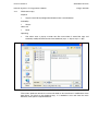
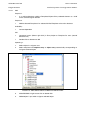
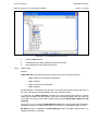
As Windows Application, PACiS SCE can be started for example by:
1.
Desktop shortcut
2.
Windows Explorer selection
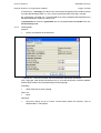
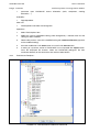
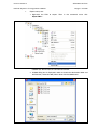
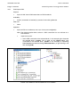
C:\Program Files\Schneider Electric\PACiS\sce\4.46
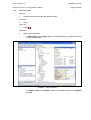
FIGURE 5: EXECUTABLE PATH
2.2
3.
Start-up/Execute option and typing PACiS SCE
4.
Start-up/Program/PACiS/Configuration Editor X.Y/ SCE selection
Leaving PACiS SCE
To stop PACiS SCE use the File/Exit option.
SCE/EN HI/C40
User Interface
Page 10/208
2.3
PACiS System Configuration Editor
PACiS SCE General Display
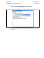
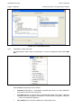
At initial start-up or after installation of new version, the PACiS SCE application display can
be seen as represented below (as far as user has all PACiS SCE rights and licences). It
should be noticed that all parts are not necessary needed for all kind of user.
FIGURE 6 - PACiS SCE DISPLAY AT START-UP
The starting view is empty. Explanation of each area is given below with some information
on it. For displaying information it is needed to load an example or delivered database. This
loading explained in detail later is done.
Menu bar: File/Open and classic window search of a database.
User Interface
SCE/EN HI/C40
PACiS System Configuration Editor
Page 11/208
After such database load, the PACiS SCE application looks as below.
FIGURE 7: PACIS SCE DISPLAY WITH LOADED DATABASE
The display is composed of 5 areas:
•
Title Bar
•
Menu Bar
•
Tool Bar
•
Docking Window or common work area composed of several on line optional and
customisable areas:
•
−
Template List Tree Viewer
−
Template Entry Tree Viewer (of selected item in Navigator)
−
Object Entry Tree view (of selected item in Navigator)
−
Template/Object Navigator
−
Object/Template Contents List (of selected item in Navigator)
−
Attributes List (of selected Item in Navigator)
−
Graphic area
−
Traces List Viewer
Status Bar
SCE/EN HI/C40
User Interface
Page 12/208
2.3.1
PACiS System Configuration Editor
Title Bar
FIGURE 8: TITLE BAR
This Title bar provides:
−
the name of the product PACiS Configurator synonym of System Configuration
Editor,
−
the full file name of the active database (including its path),
−
optionally if database is read only.
On the right of title bar are displayed three window standard buttons
Set application as icon in Window Task Bar,
Maximise/minimize application windows
Close/Exit the application.
When the PACiS SCE window is minimised its size remain unchanged, covering fully the
screen. Resizing corners and hedges are usually hidden by Windows Application Bars. To
resize the minimised PACiS SCE window, it is needed to select the title bar and move it. It is
then possible to select window border for a resize operation.
2.3.2
Menu Bar
The menu bar is composed of 8 Sub-Menus described in detail in next chapter
FIGURE 9 - MENU BAR
File
All Files operations including generation
Edit
All Edition operations
User
PACiS SCE access control right management
Graphic
All graphical actions (done in Graphic Area)
Workbenches
All relations with ISaGRAF and FBD editors
Tools
PACiS SCE parameters and internal tools
Window
All PACiS SCE work areas management
Help
Help index
User Interface
SCE/EN HI/C40
PACiS System Configuration Editor
2.3.3
Page 13/208
Tool bars
Three tool bars are available. They could be independently displayed and positioned.
The tool bars display is managed by Menu/Window/Common, OI Mimic and Computer mimic
Toolbar.
FIGURE 10 - COMMON, OI MIMIC AND COMPUTER MIMICS TOOL BARS
2.3.4
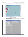
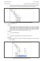
Working or Docking Window
By default, the working area is displayed with all areas as below.
Areas are viewers driven by:
•
Navigator perspective Tree Viewer: presents a hierarchical view of the configuration.
Three roots are defined: electric (Site), system (Scs) and graphic. Its behaviour is the
same than the left part of a window explorer.
FIGURE 11: - NAVIGATOR
SCE/EN HI/C40
Page 14/208
•
User Interface
PACiS System Configuration Editor
OI Mimic Editor: this editor is displayed in the graphic area and is used to edit the OI
mimics.
FIGURE 12: OI MIMIC EDITOR
•
Computer Mimic Editor: this editor is displayed in the graphic area and is used to
edit the bay mimic of C264 HMI.
FIGURE 13: COMPUTER MIMIC EDITOR
User Interface
SCE/EN HI/C40
PACiS System Configuration Editor
•
Page 15/208
Bitmap Editor: this editor is displayed in the graphic area and allows editing the
bitmap file which is used during Computer mimic edition. The bitmaps are stored in a
bitmap table.
FIGURE 14 - BITMAP EDITOR
•
Template navigator: presents the list of all templates defined in the current
configuration database.
FIGURE 15 - TEMPLATE LIST
SCE/EN HI/C40
Page 16/208
User Interface
PACiS System Configuration Editor
When selecting object (click, enter) all viewers are “refreshed” with corresponding data:
•
Template Entry List: views the existing templates which can be added under the
selected object.
FIGURE 16 - TEMPLATE ENTRY LIST
•
Object Entry List: displays the list of objects which can be added under the selected
object. This list is presented in a tree view: for example: all boards which can be
added under a C264 are presented under a folder named Board. The content of this
view depends on existing objects under the selected object: if the maximum number of
cards with a specific type is reached, this kind of card is deleted from this helper view.
FIGURE 17: OBJECT ENTRY WINDOW ASSOCIATED TO A COMPUTER
User Interface
SCE/EN HI/C40
PACiS System Configuration Editor
•
Components List: objects/relations under selected object. Its behaviour is the same
than the right part of a window explorer.
FIGURE 18 - COMPONENTS LIST
•
Page 17/208
Attributes List: the configurable attributes of the selected object.
FIGURE 19: ATTRIBUTES OF AN OBJECT
SCE/EN HI/C40
User Interface
Page 18/208
2.3.5
PACiS System Configuration Editor
Status Bar
At the bottom of the screen, is displayed a set of information relative to PACiS SCE
Application run time messages.
FIGURE 20 - STATE BAR
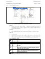
With 4 contextual labels from left to right:
1.
PACiS SCE Application run time message or selected Object/Template name and
type.
2.
Read/Write property of the object.
3.
Object / Template mode.
4.
Coordinates of cursor in the OI or Computer Mimic editor.
2.4
Management under Windows 2000 & XP
2.4.1
Windowing
The PACiS SCE Application follows windowing behaviour. As presented before it has all
option to set as an icon, maximise/minimise, or close/exit.
Each internal window (included tool bar) is managed with the following dock/float window
features:
•
dock window anywhere,
•
window can be fixed in the screen,
•
change dock/float states by double clicking,
•
window can be either attached to or detached from the tabbed components,
•
save and load dock/float states when user exits and enters in the PACiS SCE
Application.
When window is minimised it can be resized by its border or corner, and displaced by
dragging of title bar. This behaviour is also down with sub windows.
2.4.2
ToolTip
When mouse pointer remains on tool bar icon or menu, a tool tip appears with a short
message explaining the function.
User Interface
SCE/EN HI/C40
PACiS System Configuration Editor
3.
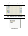
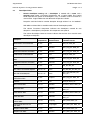
PACiS SCE DETAILED WINDOWS DESCRIPTION
3.1
Tools Bar
Page 19/208
The tool bar can have separate groups of tools displayed by Menu/Windows/Tools option.
The associated functions are detailed in following chapter.
3.1.1
Common Tools
Set of statistically most commonly used control (also defined in menu bar)
FIGURE 21 - COMMON TOOL BAR
Switch between Template and Object Mode
New File Database or Library
Open Database or Library
Save current File (Database or Library)
Cut Selected Object/Template
Copy Selected Object/Template
Paste/Duplicate Selected Object/Template
Delete Selected Object/Template
Add Mimic Editor Area into Dock window
Reset the default perspective of Dock / Float windows
Switch Dock window focus on Navigator Perspective
Switch Dock window focus on Graphical Perspective
Show/Hide the grid
Zoom +
Zoom Anti-aliasing effect
SCE/EN HI/C40
User Interface
Page 20/208
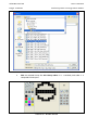
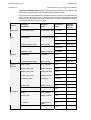
3.1.2
PACiS System Configuration Editor
OI Mimic Tools
Set of statistically most commonly used graphic control (also defined in menu bar) for OI
Mimic graphical editor.
FIGURE 22 - OI MIMIC GRAPHICAL EDITOR TOOL BAR
Create a line
Create a rectangle
Create a circle
Create a polyline
Create a text
Create a variable text
Create a memo icon
Create an image
Group edition
Exit group edition
Group Selected Graphic Objects
Ungroup Graphic group object
Rotation 90°
Flip
Mirror
Graphic Object at Bottom plane
Graphic Object at Backward plane
Graphic Object at Forward plane
Graphic Object at Top plane
Scrolling list of alignment functions
Scrolling control
Align Horizontal Top
Align Horizontal Centre
Align Horizontal Bottom
Align Horizontal Side by Side
Align Vertical Left
Align Vertical Centre
Align Vertical Right
Align Vertical Side by Side
User Interface
SCE/EN HI/C40
PACiS System Configuration Editor
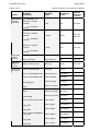
3.1.3
Page 21/208
Computer Mimic Tools
Set of statistically most commonly used graphic control (also defined in menu bar) for
Computer Mimic graphical editor.
FIGURE 23 - MICOM C264 MIMIC EDITOR TOOL BAR
Create an horizontal line
Create a vertical line
Create a text
Insert a bitmap
Create a module
Create a transformer module
Module edition
Exit module edition
SCE/EN HI/C40
User Interface
Page 22/208
PACiS System Configuration Editor
3.2
Docking Window
3.2.1
Docking Window Management
The main working area uses a display principle called docking. It is made for flexible
management of several sub-areas.
•
inserted with dependency in the docking window or
•
separate window.
A docked area supports any kind of editor: tree browser, list, graphic, As window sub-object,
area can be resized by its edge, moved by its title bar, or closed by the cross on upper right
corner.
When the docked area is a separate window, it is handled like any window and can be
dragged to separate screen display (when PC has multiple screens), or on extended virtual
desktop part. The separated window remains over its father PACiS SCE application window,
like a more known pop-up. This window can not be set in icon.
When the docked area remains in dock window, its size is adjusted to other docked area
and especially a main docked area. The main docked area is selected in the Window Menu.
It is proposed the object/template navigator perspective or the graphical area perspective
which supports all graphical editors. All other docked areas are automatically adjusted from
this first area.
An area could be pinned or not: if it is pinned, its view is permanent, if it is not pinned; the
area is displayed only when the mouse points on it.
An area could be attached to or detached from the tabbed components: several areas are
displayed on the same window, the user works on each area through its tab button.
3.2.2
Selecting displayed area in working window
The menu bar in sub menu Windows helps to select or deselect the areas seen in working
window area. When an item is clicked, a tilde appears before all activated area. Another click
deselects the given area from the working window area.
FIGURE 24 - AVAILABLE AREAS
Area unselecting can be done also by a click on its cross on upper right corner, except for
the main area (navigator or graphic editor).
User Interface
SCE/EN HI/C40
PACiS System Configuration Editor
3.2.3
Page 23/208
Moving/placing areas into working window area
The size of the PACiS SCE application determines the size of its inner docking windows.
Most of the time, PACiS SCE window is maximised. When new docking areas are added by
menu bar, they are displayed as “docked”, in the docking window, at default location. Then
all docked areas are resized.
Working with PACiS SCE, a user may need to:
•
resize docked area or
•
modify docked position relatively one to others.
To resize docked area without changing disposition of areas, a mouse click on border or
edge allows a resizing of this area in horizontal or vertical direction. As docking window size
is then fixed, other docked areas are then resized in same directions.
To modify the area disposition or how they are placed relatively one to the other, the user
has to click on one area header. Since a rectangle appears. While still right mouse pressed,
the rectangle representing area can be dragged. This control rectangle can change in shape
or colour.
If mouse pointer is released when control rectangle is still blue, the moved area while be
dropped in docking window. If the key is release when rectangle is grey, the moved area
becomes a moveable window out of dock window and PACiS SCE main window.
If control rectangle is blue and dragged to the boundary of docked area it changes its shape.
New shape is still rectangle but different sizing, square, flat vertical or flat horizontal. The
new shape in blue is a “proposal” new positioning of the moved area into the docking
window, relatively to other docked areas. A key release drops then the moved area in new
relative position in docking window.
It is possible at any moment to get back the default configuration of windows by select Reset
Perspective item
in Window menu.
SCE/EN HI/C40
Page 24/208
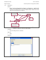
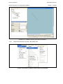
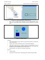
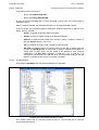
3.3
User Interface
PACiS System Configuration Editor
Navigator
It is the main window to select template/object. It is the central area in docking window
management (like also graphic area) when Navigator Perspective
(Windows menu) has
been chosen. This area should not then become a stand-alone window.
FIGURE 25: NAVIGATOR PERSPECTIVE
In any case the main interest is on the selected object (here the object Substation is in grey
background). All other docked area refers to this object.
The navigator has a panel on its top which allows to browse into the list of the last visited
objects.
There are seven buttons which have the following functions:
Favourite: reaches to the favourite object, if it is defined. The combo list allows to
visualise the path of the favourite object and to set a new one.
Back: reaches to the previous selected object, if it is defined. The combo list allows
to visualise the complete list of the previous visited objects and to select one of
them.
Forward: reaches to the next selected object, if it is defined. The combo list allows
to visualise the complete list of the next visited objects and to select one of them.
Collapse sub tree: collapses the current selected object and all components of this
object. Allow to free memory used by its components.
Sort: sorts all short names of the children components of the selected object with
alphabetic order.
This button is used to toggle the last check box (among the three described here
after) which has been accessed by the user.
User Interface
SCE/EN HI/C40
PACiS System Configuration Editor
Page 25/208
When this button is clicked the following submenu is displayed
The first check box is used to show (when selected) or hide ( when unselected) the
complete relations
The second check box is used to show (when selected) or hide ( when unselected)
the uncompleted relations
The third check box is used to show (when selected) or hide ( when unselected)
the spare objects or spare templates.
Theses buttons are used in all tree representations of PACiS SCE; with the same behaviour.
This behaviour is not re-defined elsewhere in this document.
The navigator is a standard tree viewer allowing with + and – to expand, reduce browsing of
object components.
Icon indicates properties of objects.
They are different in template or object mode.
Icons
Database
Properties
Template
Main Electric Parent
Template
Main System Parent
Template
Main Graphic Parent
Both
Configurable component
Both
Folder or Binder
Both
Template Anchor (Parameter)
Both
Template Instance Anchor (Parameter)
Both
Template root
Both
Complete or Full Filled Relation
Both
Incomplete Relation
Both
Complete and Fixed Relation
Relation representation is defined via toggle buttons,
filter or to display relations on navigator.
and
. Theses buttons allows to
A double click on an object expands it.
In navigator and content window, the labels of Spare objects are greyed and italic. For
sparing an object, set the Object attribute spare to Yes.
SCE/EN HI/C40
Page 26/208
3.4
User Interface
PACiS System Configuration Editor
Components List
FIGURE 26 - COMPONENTS LIST VIEWER
The components list gives the same sub-object that navigator expands. But it provides two
other columns with the object type, and object description.
Sorting can be made by Name, Type or Description by clicking on header.
Relations, content drawings are the same that navigator, with same visibility rules. The
behaviour of mouse operation is the same. A click on an object changes focus. A double
click on a relation opens the Relation link editor dialog box..
FIGURE 27 - RELATION LINK EDITOR
User Interface
SCE/EN HI/C40
PACiS System Configuration Editor
3.5
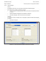
Page 27/208
Attributes List Editor of Object/Template
Attributes are displayed in the editor as a table. Attributes are organised in categories
(different tables with tabs) and sub-categories (different separators within a table).
FIGURE 28: ATTRIBUTES LIST EDITOR
Relation attributes are displayed as normal attributes in a tab Relation. The path of linked
object is also displayed as an attribute in a category Relation. If the relation is filled (i.e. the
link is defined), the attributes of linked object are also displayed and editable while the
relation edition. This allows to minimize the navigation between objects.
FIGURE 29 - RELATION ATTRIBUTES LIST EDITOR
If the relation is filled (i.e. the link is defined), the attributes of linked object are also displayed
and editable while the relation edition. This allows to minimize the navigation between
objects.
FIGURE 30 - RELATION ATTRIBUTES OF LINKED OBJECT
SCE/EN HI/C40
User Interface
Page 28/208
PACiS System Configuration Editor
Attribute value modification is done by selecting a value in a list, or by double-clicking in the
field to edit.
The value representation is different for:
•
•
Attribute not linked to a template:
−
Read/write: white,
−
Read-only: greyed.
Attribute linked to a template:
−
Read/write: white, its short name font colour is blue in the template mode,
−
Read-only: greyed.
Parameters are displayed as attributes in the Parameter category.
FIGURE 31 - PARAMETERS LIST EDITOR
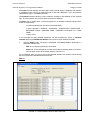
The contextual menus, available with a right click, are:
3.6
•
Cut: initiate the Cut action
•
Copy: initiate the Copy action
•
Paste: initiate the Paste action
•
View linked attributes
Database Entries
The Database entry is composed of three areas whose purposes are different in the cases
listed below.
3.6.1
Templates list
The Templates list contains all templates that are in the opened database(s).
The main database is the first opened database. It can be opened in update mode (work
version) or read-only mode (referenced version).
FIGURE 32 - TEMPLATE LIST AREA
User Interface
PACiS System Configuration Editor
SCE/EN HI/C40
Page 29/208
The second database is the second opened database. It is mandatory opened in read-only
mode. The System allows to open the second database only if the main database is opened
in update mode.
FIGURE 33 - TEMPLATE LIST AREA WITH A SECOND OPENED DATABASE
These templates are split in two tabbed panes, one for main database, and other for second
database. If only main database is opened, the second tabbed pane is not visible. The
tabbed panes have a ToolTip which give the name of opened database.
The Templates list and Templates entry are defined as a flat list of templates. The list root is
specialised for the Templates Lists and the Templates entry (contains the type of the
object/template selected in the Navigator).
The list is organised as follows:
•
Electrical, then System, then Graphical templates.
•
Alphabetical order on Anchor template type.
•
Alphabetical order on Anchor template short name.
The list root ToolTip contains the name of the corresponding database (main database in
Main Template List, second database in Second Template List).
This area is used to:
•
Select a template to edit, in template mode,
•
Transfer a template from second database to the main database: the template must
be selected from second database templates list. On this template a contextual menu
Add allows to copy this template to the main database. The template is then added
into main database templates list.
SCE/EN HI/C40
Page 30/208
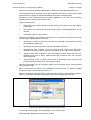
3.6.2
User Interface
PACiS System Configuration Editor
Templates entry
The Templates entry contains the templates that can be added as a child of the selected
element in the Navigator. It is therefore a contextual area.
A contextual menu item allows to add the current template under the current selected object
from the navigator.
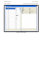
Hereafter, an example of a templates entry area.
FIGURE 34 - TEMPLATE ENTRY AREA
It represents all templates which can be added under a voltage level. This voltage level is the
selected object in the Navigator view.
3.6.3
Objects entry
The Objects entry contains the types (objects/templates and relations) that can be added as
a child of the selected element in the Navigator. It is therefore a contextual area. These
types are displayed as a tree, and organised with abstract types.
A contextual menu item allows to create an object with the selected type under the current
selected object from the navigator.
Hereafter, an example of an objects entry area for a voltage level objects. It represents all
objects which can be added under a voltage level. This voltage level is the selected object in
the Navigator view.
FIGURE 35: OBJECT ENTRY AREA
User Interface
SCE/EN HI/C40
PACiS System Configuration Editor
3.7
Page 31/208
Graphic Area
This graphic area is represented by a moveable window.
It is the central area in docking window management (like also Navigator) when Graphic
Perspective
(Windows menu) has been chosen.
It can receive various editors in according to the selected object in the Navigator and the
selected attribute in the attributes editor.
As all objects, the graphic objects can be manipulated from the Navigator. Nevertheless, the
graphic editor is helpful to create graphic objects, by showing a graphical representation of
the objects.
Currently, the available editors are:
•
OI Mimic Editor: to build the OI Mimics used by the operator interface,
•
Computer Mimic Editor: to build the Computer Mimics used by the MiCOM C264
front panel HMI.
•
Bitmap Editor: to build the bitmaps also used by the MiCOM C264 front panel HMI..
A complete description of these editor is done in section Graphic menu, see § 4.4.
SCE/EN HI/C40
User Interface
Page 32/208
4.
PACiS System Configuration Editor
PACiS SCE MENU COMMAND
All PACiS SCE actions are available through the menu bar items and/or contextual menu
items.
Availability of theses items is contextual. For example, Edit/Paste is enabled if an object has
been cut/copy before and a potential parent object has been selected in navigator. Theses
conditions are described for each action.
4.1
File Menu
FIGURE 36: FILE MENU
A database is either a configuration database or a library database. A configuration
database contains templates and a configuration which uses theses templates. A library
contains only templates.
Database could have some different storing format:
•
a compressed file: the database is a compressed file that contains all files of the
database.
•
a sub tree directory: the database is a directory and its files sub tree.
The storing format of a database is indicated by its file/directory extension. e.g.:
•
.mpc: database configuration file
•
.mpl: database library file
•
.dpc: database configuration directory
•
.dpl: database library directory
Each database is composed of several versions: a working version and some referenced
versions. The working version can be updated (read and write), whereas referenced
versions are frozen (read only).A Check In mechanism is used to reference the working
version: it becomes a referenced version. A Check Out mechanism is used to transfer a
referenced version to the working version.
No more than two databases can be opened simultaneously in the PACiS SCE:
•
The first opened database is the main database. It can be the working version
(opened in update mode) or a referenced version (opened in read-only mode).
User Interface
SCE/EN HI/C40
PACiS System Configuration Editor
•
Page 33/208
The second opened database is the second database. It can be opened only if the
main database is the working version. It can be the working version or a referenced
version (both opened in read-only mode). This second database is only used to
transfer template from a database to the main database. This second database could
be a configuration database or a library database. In both case, only the template part
of this database is used to transfer some template from second database to the main
database.
The item of menu file applies only to the main database, except the Open and Close actions
that may also apply to the second database:
second db is opened in
readonly mode.
It could be a working or
frozen version
only save the main
db : the working
version
save
only working
version
no database
(db) is opened
the save action is
applied on t he MAIN db
and not on the second
db (opened in readonly
mode)
open RW
save
open
close
a working db
is opened
new
close only t he
second db
creat e a new db,
and an initial
version : a working
version
frozen
version
before ALL save
action (on the
working version), a
backup copy is
done.
a working db and a
second db are opened
open R
if t he db has been
updated, a save action
is applied after
operator confirmation,
then the main db is
closed.
close the
main db
a referenced db
is opened
close
close
no database
(db) is opened
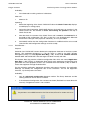
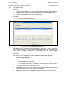
S0211ENa
FIGURE 37 - MAIN / SECOND DATABASES
The naming rule of database is the following:
Referenced version is a file/directory with indices: v.r[.m]. e.g.:
databaseName.1.1.3.mpc
indices range is 0..99,
third index (m) is optional and is used for partial generation use case.
database name contains any alphabetic or numeric character or “_” or “-“. Blank character is
forbidden. This rule must be applied for database path also.
Work version of the configuration has no indices.
databaseName.mpc
SCE/EN HI/C40
Page 34/208
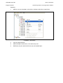
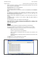
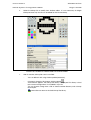
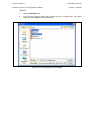
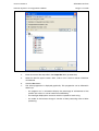
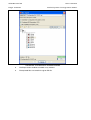
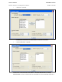
4.1.1
User Interface
PACiS System Configuration Editor
File/New…
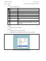
Purpose:
•
Create a new working library(.mpl, .dpl) or configuration database (.mpc, .dpc)
Availability:
•
No database loaded, or no working database.
Other call:
•
Shortcut: Ctrl+N
•
Toolbar
Operating:
•
The action is available from start-up or if all loaded database have been closed. After
this new action it is possible to open second database to pick-up data/templates.
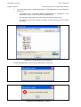
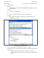
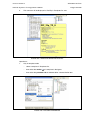
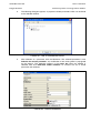
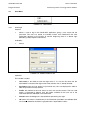
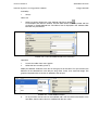
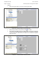
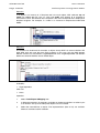
FIGURE 38: - FILE/NEW DATABASE
1.
Browse the drive and directories selections to define where to store new file or
directory
2.
Enter a name for the New database in “File Name” area
3.
Select the kind of database in “File Type” area with: mpc for configuration, or mpl for
library
4.
Validate by clicking the New button or enter in “file name” area
A first working file or directory is created. An empty working database is available under
PACiS SCE interface.
With previous naming rules, the name is free, but a good practice is to put PACiS SCE
software version at its beginning.
User Interface
SCE/EN HI/C40
PACiS System Configuration Editor
Page 35/208
Example:
04_34_myDb.mpc
Path of database must contain only alphabetic or numeric character or “_” character or “-“
character.
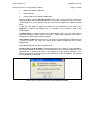
If the given name is wrong a warning message is displayed:
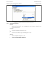
FIGURE 39: WRONG FILE NAME FORMAT
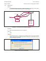
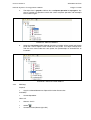
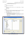
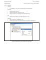
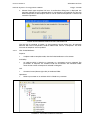
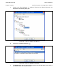
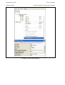
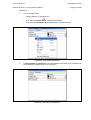
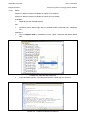
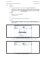
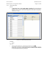
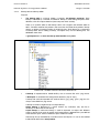
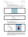
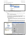
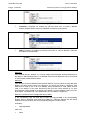
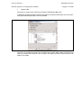
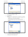
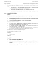
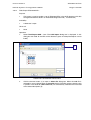
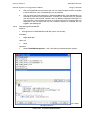
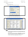
4.1.2
File/Open…
Purpose:
•
Open an existing library/configuration database as main or second database. If no
database already opens, it opens a main working database. If a work database is
already opened, a second database is opened in read only, for copy of object to the
working database.
Availability:
•
Only two databases can be opened simultaneously
Other call:
•
Shortcut: Ctrl+O
•
Toolbar
Operating:
•
The action is available from start-up, or when a main database is already defined. A
pops up appears for selecting the database.
SCE/EN HI/C40
User Interface
Page 36/208
PACiS System Configuration Editor
FIGURE 40: FILE/OPEN DATABASE
1.
Browse directories to select the file to load with drive selection and directories
2.
Select a filter with the kind of database in “File Type” area with: mpc for configuration,
or mpl for library
3.
Click on file name or enter the name of the database to load in “File Name” area
4.
Check comments in write panel
5.
Validate the selected file by clicking the Open button
The database is opened in a temporary directory (.mpx). By default, this temporary
directory is an uncompressed copy of database that is created under the directory where the
database is stored.
This directory where this temporary directory is created could be set explicitly via two
PACiS SCE settings (tools/option).
The temporary directory could be directly the directory of database. This option is set by a
PACiS SCE setting (tools/option) and is available for directory database format (.dpc, .dpl)
only.
The read/write mode is displayed in title bar.
When PACiS SCE reads the open database, it checks with which PACiS SCE version it has
been saved. If the PACiS SCE version was older, then some upgrades can be necessary:
for example, adding a new attribute to an object, modifying the cardinality of an object, etc. In
this case, the following dialog box is displayed:
FIGURE 41: FILE/OPEN WITH DATABASE CONVERSION
User Interface
SCE/EN HI/C40
PACiS System Configuration Editor
Page 37/208
If answer is “Yes”, then database is automatically upgraded to the new PACiS SCE data
model. This upgrading is available only for a working version.
The upgrading process could be more complex, especially when new structure of databases
is incompatible with the structure of database to open. In this case, the database must be
saved with a special command: “prepare upgrade & save”. Then opening this kind of
database is available.
4.1.3
File/Close
Purpose:
•
Close opened library/configuration database as main or second database.
Availability:
•
when a database has been opened.
Other call:
•
Main window close button
Operating:
•
The name of the database is already defined from Open/New. If main database is a
working database and some modifications have been done, it asks to Save the
database:
FIGURE 42: - FILE/CLOSE ASKING FOR SAVE WORK DATABASE
•
4.1.4
If a second database is opened, it’s closed and the working database is still opened.
File/Save
Purpose:
•
Save the working opened library/configuration database. Second database can not be
modified and does not need a save action.
Availability:
•
Only the working version of a database (read/write) can be saved
Other call:
•
Shortcut: Ctrl+S
•
Toolbar
•
Main window close button if database has been modified
Operating:
•
Only the working version of a database (read/write) can be saved
SCE/EN HI/C40
Page 38/208
4.1.5
User Interface
PACiS System Configuration Editor
File/Prepare upgrade & Save
Purpose:
•
Save the main opened library/configuration database and put into the database file an
xml form of the database. This xml form could be used during opening operation if the
structure of the data model has been changed (see File/ Open)
Availability:
•
Only the working version of a database (read/write) can be saved with this option
Other call:
•
None
Operating:
•
4.1.6
An xml backup of the database is done. This xml backup is stored in .mpc file.
File/Clean & Save
Purpose:
•
Compact the main opened library/configuration database and save it. The compaction
consists to delete the space not used in database file: when an object is deleted, its
space is not freed.
Availability:
•
Only the working version of a database (read/write) can be cleaned and saved.
Other call:
•
None
Operating:
•
An xml backup of the database is done. This xml backup is stored in .mpc file.
User Interface
SCE/EN HI/C40
PACiS System Configuration Editor
4.1.7
Page 39/208
File/Create a copy
Purpose:
•
Copy the main library/configuration database into a new database.
Availability:
•
Always
Other call:
•
None
Operating:
•
The action starts a pop-up to enter new file name where is stored the copy and
eventually modify the store format of the database (.mpc <> .dpc or .mpl <> .dpl):
FIGURE 43: COPY FILE CHOOSER
The current database remains the same and needs to be saved later if modifications have
been done. To switch to the database copy, it is needed to save and close the main
database, then open the copied database.
SCE/EN HI/C40
User Interface
Page 40/208
4.1.8
PACiS System Configuration Editor
File/Check in…
Purpose:
•
Save the current working database (template or configuration) in a referenced file
version. The working database is not saved but only copied. The “check in” file is
named like work database with increment of database version. Check in file is then
read only from PACiS SCE until a check out.
save A s action allows to
copy of a db version in a
new db and the working
version of this new db.
A frozen
version
save As
save, save As
checkin
THE working
version
MULTIPLE
version are
available
checkout
only ONE vorking version for a
db : so some warning are done
during checkin/checkout
operat ion t o prevent some data
crash.
S0209ENa
FIGURE 44 - CHECK IN / CHECK OUT MECHANISM
Availability:
•
Only with working version of a database
Other call:
•
None
Operating:
FIGURE 45: FILE/CHECK IN WORKING DATABASE
User Interface
SCE/EN HI/C40
PACiS System Configuration Editor
1.
Select new reference identifier
2.
Write comments
3.
Confirm check-in by clicking the OK button
Page 41/208
A pop-up window asks for identifier increment with major or minor evolution. PACiS SCE
computes directly the proposed identifier from current one. In example it starts from 0.0. If
current identifier is 3.5 it proposes 3.5.0, 3.6, and 4.0. This reference is added to the file
name.
A field text area allows to precise the content or the modification of the version. This
comment is stored in the database file. It is possible at any moment to read it with
File/Properties.
A good practice is to keep reference 0.x for development, and 1.x, 2.x for major steps of
project life: prototype, Factory version, site version… Major index modification can be also a
consequence of PACiS SCE software evolution.
Three indices versions (for example 3.5.1) are used for partial generation of database: only
a subset of devices are taken into account during device configuration files process
(file/generate).
The loaded database is still the working database.
‘Check in’ does not mean Check: a referenced version (with a check in) is not mandatory a
full consistent database (test done with Check operation). An inconsistent database can be
referenced but a warning message is then displayed. During opening operation, if the
working version does not come from the latest referenced version of database, the following
warning dialog box is displayed:
FIGURE 46: FILE/OPEN AND CHECK IN WORKING DATABASE
SCE/EN HI/C40
User Interface
Page 42/208
4.1.9
PACiS System Configuration Editor
File/Check out
Purpose:
•
A referenced database could not be modified (read only). The check out action allows
to transform the referenced database into a working database.
A frozen
version
s ave As
s ave As
c hec kin
THE work ing
version
check out
myDb.mpc
myDb.0.1.mpc
myDb.0.2.mpc
myDb.0.3.mpc
myDb.0.5.mpc
myDb.1.0.mpc
myDb.1.1.mpc
myDb.2.0.mpc
... .
S0210ENa
FIGURE 47 - FILE/CHECK OUT DATABASE, EXAMPLE
Availability:
•
Only with loaded referenced version of a database
Other call:
•
None
Operating:
•
The referenced version is copied into the working version. The previous working
version is overwritten. If the referenced version to check out is not the latest version, a
warning dialog box is displayed:
FIGURE 48: FILE/CHECK OUT WARNING
User Interface
SCE/EN HI/C40
PACiS System Configuration Editor
4.1.10
Page 43/208
File/Check
Purpose:
•
Check the main library/configuration database consistency. The action starts testing
on whole database. The templates and the spared objects are not taken into account
by the check function. The complete definition of errors/warnings is available in
chapter PACiS SCE/EN MF.
All errors/warnings are displayed in the following table of the Trace panel ("Checks"
tab):
FIGURE 49 - ERROR / WARNING CHECK TABLE
Table rows: each row corresponds to one check operation whose result is an error or a
warning.
Table columns:
−
Level: it displays an icon for error or warning.
−
Type: it contains the identifier of the check operation displayed in the row.
Example: "DataObjectPhases" is a check consisting in verifying that all the phases
under a GenWYE or GenDELTA DataObject, is linked, through the "has for
IEC61850 address" relation, to distinct Datapoints.
−
Reference: for each check operation, an object implicated in the check operation,
is considered as the main object. The column displays the path of this object. If the
user activates the "Reach" action on the row, this object is retrieved in the
PACiS SCE navigator and selected. This action is also available with double-click.
−
Message: it displays a message explaining the error/warning for the check
operation.
−
First column: the user can check On/Off this column to remember which
error/warning he tried to correct.
The panel of the Table contains also the following buttons:
−
Errors filter toggle button: if this button is selected, the Error traces are not
displayed (they are filtered). Else they are.
−
Warnings filter toggle button: if this button is selected, the Warning traces are
not displayed (they are filtered). Else they are.
−
Info filter toggle button: if this button is selected, the Info traces are not displayed
(they are filtered). Else they are.
−
Checked traces filter toggle button: if this button is selected, the Checked traces
are not displayed (they are filtered). Else they are.
SCE/EN HI/C40
User Interface
Page 44/208
PACiS System Configuration Editor
Availability:
•
For referenced or working version of a database
Other call:
•
Shortcut: F6
Operating:
4.1.11
1.
Before the beginning of the check, PACiS SCE clears the Check Traces tab, displays
it and displays a waiting popup
2.
During the check computing, PACiS SCE displays the found errors or warnings in the
Check Traces tab. The number of errors and warning are updated at the top of
Check Traces tab
3.
After the check, the content of the Check Traces tab is saved in the check.txt file in
the folder of the configuration. This file is a text file. It can be displayed in Microsoft
Excel with the file type: Text (separator: tabulation), or in any text editor.
4.
PACiS SCE notifies that the Configuration Database is modified and has to be saved
(check.txt file and Configuration settings are to be saved).
File/Generate…
Purpose:
Generate from PACiS SCE current database the equipment database to load into system
devices. This equipment database is a Zip file which is used by the SMT (System
Management Tool). It’s called System Data Bag (*.sdb). There is no software interface
between SMT and PACiS SCE. The exchanges are done manually with files.
This System Data Bag contains all device configuration files which are named Application
Data Bags (*.adb). There’s an Application Data Bag for each equipment configuration to be
generated. For each equipment, there’s also a Maintenance Data Model (*.dm) for SMT to
access the equipment through the Station Bus.
For the simulation application (equipment simulator and process simulator), the application
databags are directly the configuration files of the simulators: .xml for the equipment
simulator, .zip for the process simulator.
Availability:
•
Only for referenced configuration database version. The library database and the
working database version are not available.
•
If the referenced configuration has not been consistent (file/check has been done with
no error), File/generate action is not available.
FIGURE 50 - CHECK WARNING FOR NO-CONSISTENT
OR OBSOLETE CONSISTENT CHECK
User Interface
SCE/EN HI/C40
PACiS System Configuration Editor
Page 45/208
Other call:
•
Shortcut: F7
Operating:
1.
File/Open a referenced (and check in) version. This means that in common cases, the
user may have to:
−
check in its working database,
−
notice the check in the new version reference,
−
save the working database for future modification,
−
close the working database,
−
open the database with new referenced version.
2.
Select File/Generate…
3.
A Generation dialog box lists all SBus devices available on database and allows to
select a part or all of them. The spare devices are not displayed.
4.
Only if referenced version has a third index, select the devices. Otherwise all devices
are pre-selected.
5.
Select the output directory, where the System Data Bag will be generated, with the …
button.
6.
Click the Run button.
FIGURE 51: FILE/GENERATE DIALOG BOX
SCE/EN HI/C40
Page 46/208
7.
User Interface
PACiS System Configuration Editor
The action progression is displayed graphically. This progression can be followed in
three ways:
-
the progress bar is animated to display the percentage of achievement of the
process (the value is a ratio of number of treated items),
-
the messages displayed on status bar which are specific of each using,
-
the nodes of the browser change in function of their processing state to follow
processing.
FIGURE 52: FILE/GENERATE PROGRESSION
At the end of generation the final result of generation is presented.
FIGURE 53 - FILE/GENERATE … SUCCESSFUL
FIGURE 54 - FILE/GENERATE … ERROR
User Interface
PACiS System Configuration Editor
SCE/EN HI/C40
Page 47/208
A third result is a warning that indicates that some C264 configuration files could be too big
for C264 downloading by SMT. It’s only a warning and the System Data Bag is created.
So, If generation succeeds, the *.zip generated file is to be provided to SMT equipment that
download equipment databases from the .zip
A good practise is to launch a generation only for a checked referenced version which has
no consistency error.
4.1.12
File/Properties
Purpose:
•
Display all properties of the database:
FIGURE 55: - FILE/PROPERTIES SETTING MANAGER ON WORK DATABASE
Only Languages used during File/Generate for OI and C264 localization could be updated.
Theses fields could be also updated through Tools/Languages.
Availability:
•
When database has been opened
Other call:
•
None
Operating:
•
Leave this display by Ok or Cancel. Cancel button restore the previous value of
editable field, i.e. Description.
SCE/EN HI/C40
Page 48/208
4.1.13
User Interface
PACiS System Configuration Editor
File/Exit
Purpose:
•
Leave PACiS SCE application
Availability:
•
Always
Other call:
•
Shortcut: Alt+F4
•
Window quit button or double click on title left icon
Operating:
•
If main database is a working database and some modifications have been done, it
asks to Save the database:
FIGURE 56: - FILE/EXIT AND PENDING MODIFIED DATABASE
−
If answer is Yes, current working database is saved before exit,
−
if answer is No, exit PACiS SCE application with no save,
−
if answer is Cancel, cancel exit operation, come back to edition mode.
User Interface
SCE/EN HI/C40
PACiS System Configuration Editor
4.2
Page 49/208
Edit Menu
This menu defines all available items while data edition: a data can be an object, an
attribute, a graphic representation of an object, etc. The edition can occur in the different
areas of PACiS SCE: navigator, components list, attribute editor, graphical editors, etc.
Most of these items are contextual and don’t appear directly in menu Edit: they are
defined by a contextual menu which depends on the type of selected object. This contextual
menu is available with a right click on the focus element (node of navigator, item of list entry,
graphical representation in mimic editor …).
FIGURE 57 - EDIT MENU
SCE/EN HI/C40
User Interface
Page 50/208
4.2.1
PACiS System Configuration Editor
Edit/Cut
Purpose:
•
Cut the selected object/attribute to clipboard. The cut selection is moved to a new
parent object.
Availability:
•
Context dependent
Other call:
•
Shortcut: Ctrl+X
•
Toolbar
•
Contextual menu (Mouse right click)
Operating:
1.
Select the object/attribute to cut and choose cut item. In Navigator, only one object
can be selected; in Components list, multi-selection is available (left click and shift,
left click and ctrl).
FIGURE 58 - EDIT/CUT
User Interface
SCE/EN HI/C40
PACiS System Configuration Editor
2.
Page 51/208
The object icon is greyed to indicate that a cut/paste operation is in progress. Any
copy or another cut operation cancels the current cut/paste operation and the object
icon is normal again.
FIGURE 59 - EDIT/CUT RESULT
3.
Select the new parent object/attribute where the cut object will be moved and choose
paste item. The cut object is then moved to its new parent. If an object already exists
with the same name under the same parent, the pasted object is renamed with an
increment.
FIGURE 60 - EDIT/CUT-PASTE RESULT
4.2.2
Edit/Copy
Purpose:
•
Copy the selected element to clipboard for further Paste action
Availability:
•
Context dependent
Other call:
•
Shortcut: Ctrl+C
•
toolbar
•
Contextual menu (Mouse right click)
SCE/EN HI/C40
User Interface
Page 52/208
PACiS System Configuration Editor
Operating:
1.
Select in any area the object (1 left click) or attribute (2 left click) to copy/Paste
FIGURE 61 - EDIT/COPY
2.
Copy the object/attribute
3.
Select the object under which, or the attribute to paste
4.
Edit/Paste (may be used several times) to paste copied object.
User Interface
SCE/EN HI/C40
PACiS System Configuration Editor
Page 53/208
Copy action stores all objects and all hierarchy below it. Copy action tries to keep referenced
relations.
FIGURE 62 - EDIT/PASTE
FIGURE 63 - EDIT/COPY-PASTE RESULT
SCE/EN HI/C40
User Interface
Page 54/208
4.2.3
PACiS System Configuration Editor
Edit/Paste
Purpose:
•
Paste the selected element from clipboard. This clipboard content comes from a cut
action or a copy action. See Edit/Copy and Edit/Cut.
Availability:
•
Context dependent
Other call:
•
Shortcut: Ctrl+V
•
Toolbar
•
Contextual menu (Mouse right click)
Operating:
•
4.2.4
Select object under which the paste operation should be done, then paste. Paste can
be used several times after a copy action. It inserts all hierarchy below copied object,
all attributes and all relations.
Edit/Delete
Purpose:
•
Delete the selected element: object, template, Unified Template, Parameter…
•
A general setting allows to confirm or not any delete operation.
FIGURE 64 - EDIT/DELETE CONFIRMATION SETTING
If this option is set to True, before each delete operation, the following dialog box is
displayed:
FIGURE 65: - EDIT/DELETE CONFIRMATION DIALOG BOX
User Interface
SCE/EN HI/C40
PACiS System Configuration Editor
Page 55/208
Availability:
•
Depending on the selected element and associated conditions
Other call:
•
Shortcut: Del
•
Toolbar
Contextual menu (Mouse right click) in Navigator, Components list, Templates list
4.2.5
Edit/Select all
Purpose:
•
Select all graphic objects in graphic viewers (OI Mimic viewer or Computer Mimic
viewer).
Availability:
•
The graphic viewer must have the focus.
Other call:
•
Contextual menu of graphic viewer (Mouse right click)
•
Shortcut: Ctrl+A.
•
Be care: when Navigator has the focus, Ctrl+A moves the current selection to the root.
Operations:
1.
Click to the graphic viewer or select a graphic object in the viewer.
2.
Choose Select All item: all graphic objects of mimic are selected.
FIGURE 66 - EDIT/SELECT ALL
SCE/EN HI/C40
User Interface
Page 56/208
4.2.6
PACiS System Configuration Editor
Edit/Edit relations
Purpose:
•
The relation editor is a dialog providing multiple relations creating with automatic
linking with objects.
Availability:
•
Depending on the selected element
Call:
•
Contextual menu (Mouse right click) in Navigator, Components List
Operations:
1.
Select an object from Navigator or Components list. Choose Edit relations item.
2.
This modal dialog box appears:
FIGURE 67 - RELATION LINK EDITOR
On top, the working object is remembered to know where user is working.
On bottom, two buttons: the first allows to apply modification and the other closes dialog box.
Two main parts:
−
the relation list which displays all relations available for the selected object,
−
the object tree which displays all objects available for the current selected
relation.
User Interface
SCE/EN HI/C40
PACiS System Configuration Editor
Page 57/208
A relation between two objects has a direction. So, the relation list is composed of two
tabbed pane:
−
“From” which gives relations for which the working object is the main object,
−
“To” which gives relations for which the working object is the second object.
"to" relation :
the origin of the
relation is
another objet
linked object
w orking objec t
linked object
"from" relation :
the origin of the
relation is the
working object
S0212ENa
FIGURE 68 - RELATION DIRECTION
The relation label is the name of the relation, followed by the type of object which could be
linked and then, the cardinality of the relation ([min .. max]).
User can select more than one object by checking check boxes, and when apply
modification, it creates one relation for each new selected object and removes relation with
new unselected objects, after controlling the cardinality.
So, if cardinality is respected by selection, after apply, there’s one relation for each selected
object, and no relation with others.
The object tree could be view as an object list:
FIGURE 69 - RELATION LINK EDITOR WITH OBJECTS LIST
SCE/EN HI/C40
User Interface
Page 58/208
PACiS System Configuration Editor
As user could select more than one object, the list provides same check boxes seen in
tree view, and four new icons:
4.2.7
−
Uncheck: which uncheck selected objects,
−
Check: which check selected objects,
−
Uncheck All: which uncheck all objects of the list,
−
Check All: which check all objects of the list.
Edit/Reach
Purpose:
•
Go to the linked object
Availability:
•
Depending on the selected element
Call:
•
Contextual menu (Mouse right click) in Navigator, Components List
•
Shortcut: Ctrl+G
Operations:
1.
Select relation
2.
Select Reach item in the contextual menu:
of an object in Navigator
FIGURE 70 - EDIT/REACH ITEM
User Interface
SCE/EN HI/C40
PACiS System Configuration Editor
3.
Page 59/208
The tree view is elapsed to the linked object. The linked object becomes the current
object:
FIGURE 71 - ELAPSE OF NAVIGATOR TO THE LINKED OBJECT
4.2.8
Edit/Search…
Purpose:
•
Perform contextual search on selected element.
•
This description (from step 3) remains true for a global search which is launched from
Tools/Query.
•
The query is performed:
−
for a global search, either on Objects or Templates depending on the selected
database mode when the dialog box is launched (Object mode or Template
mode).
SCE/EN HI/C40
User Interface
Page 60/208
−
PACiS System Configuration Editor
for a contextual search, only on the selected element and its own components (=
all sub tree with the selected object as root).
Availability:
•
Depending on the selected element
Other call:
•
Contextual menu (Mouse right click) of the selected element in Navigator,
Components list
•
Shortcut: Ctrl+F
Operation:
1.
Select Object from Navigator in configuration database. ( in our example, illustrated by
the three following figures the selected object is Ethernet network)
2.
Select Search… menu item.
3.
The Query Manager dialog box is displayed. It contains two areas:
−
An Instance Format containing the selection of a data type (Object, Template or
Relation) and a sublist of its Attributes.
−
A Filter optional area allowing to define a logical constraint to apply on a
selected Attribute.
FIGURE 72 - QUERY MANAGER DIALOG BOX
User Interface
SCE/EN HI/C40
PACiS System Configuration Editor
Page 61/208
The Types browser displays the data types used to create objects, templates and relations
in a database. The user has to select one type for the query definition ( In our example the
selected data type is a DIU200-210 board)
The Attributes browser displays all the attributes available in the definition of the selected
type. The user selects all or some of them for the query definition.
The Filter area is used to enter a constraint pattern on an attribute to refine the query result.
A filter is composed of:
−
an attribute identification (its label in the PACiS SCE),
−
a query operation ( EQUALS / CONTAINS / STARTS WITH / ENDS WITH /
DIFFERENT FROM / GREATER THAN / GREATER OR EQUAL TO / LESS
THAN),
−
a query value.
In our example the query defined hereabove can be translated by: search in Ethernet
network object all the DIU200-210 boards which have its spare attribute set to No.
4.
Click the Apply button. The query is performed. The Query result is displayed in a
dialog box with two tabs:
−
Edit tab: for displaying the query result table.
−
Select tab: for extracting data from the result table by selecting them in a browser.
This tab gives access to the Export function (see § 4.6.2 ).
For a contextual query, the short name of the selected element from which the query dialog
box was launched is reminded under the box title.
Edit tab:
FIGURE 73 - QUERY RESULT DIALOG BOX, EDIT TAB
SCE/EN HI/C40
User Interface
Page 62/208
PACiS System Configuration Editor
Lines are the objects, templates or relations matching the query definition. Their short name
path is displayed in the first column.
Following columns are the selected Attributes.
A cell contains the value of an Attribute.
This cell is editable with the same behaviour and the same constraints as in the Attributes
Editor.
The modification of the Attribute value is enabled only if the database is not open in readonly mode and if the Attribute is not read-only because of the User Profile rights, the
structural database locks, or the DOF status.
When an attribute value is modified an icon appears in its cell, and its previous value can be
restored.
A contextual menu is available on each attribute to copy, cut, paste, restore, or
increment the value.
The multi-selection of cells is also available for cells modifications.
All the modifications are stored in database when the Apply button is clicked. If some
modification cannot be applied to the database because of error, the modification icon
remains displayed in the cell.
Select tab:
A browser displays the objects (or templates) retrieved by the performed query.
Each object (or template) can be checked or not, to be available or not, in the export.
A contextual menu is available on each item of the browser with the following options:
−
Select to check the box of the selected it.
−
Unselect to uncheck the box of the selected item.
−
Select all children to automatically check all the boxes of the sub-items of the
selected item.
−
Unselect all children to automatically uncheck all the boxes of the sub-items of the
selected item.
The Export button saves the selected data into an xml file.
The Close button closes the query result dialog box.
FIGURE 74 - QUERY RESULT DIALOG BOX, SELECT TAB
User Interface
SCE/EN HI/C40
PACiS System Configuration Editor
4.2.9
Page 63/208
Edit/Switch Mode
Purpose:
•
Switch between Object mode and Template mode.
Availability:
•
Always
Other call:
•
Toolbar
Operations:
1.
Select switch mode item:
−
in Object mode, the navigator displays the complete object configuration and the
current selected object;
FIGURE 75 - OBJECT MODE
−
in Template mode, the navigator displays the selected template of Templates
list area;
SCE/EN HI/C40
Page 64/208
User Interface
PACiS System Configuration Editor
FIGURE 76 - TEMPLATE MODE
−
2.
for Template mode and Object mode, the other areas are updated in accordance
with the current selection of the navigator.
switch again: the current selection of template or object is saved.
User Interface
SCE/EN HI/C40
PACiS System Configuration Editor
4.2.10
Page 65/208
Move
Purpose:
•
Move an object. Same behaviour as a sequence cut/paste, with a modal editor. This
editor allows to choose the new parent of the object.
FIGURE 77 - EDIT/MOVE DIALOG BOX
Availability:
•
Depending on the selected element and associated conditions
Call:
•
4.2.11
Contextual menu (Mouse right click) in Navigator and Components list.
Replace
Purpose:
•
Replace the selected object by the content of the clipboard if objects are compatible
Availability:
•
Context dependant
Call:
•
Shortcut: Ctrl+H
•
Contextual menu (Mouse right click) in Navigator and Components list.
SCE/EN HI/C40
User Interface
Page 66/208
4.2.12
PACiS System Configuration Editor
Add
Purpose 1:
•
In a working database, add the Templates/Objects Entry selected element as a child
of the active Navigator element
Purpose 2:
•
Add the Second Templates List selected Unified Template to the main database
Availability:
•
Context dependent
Call:
•
Contextual menu (Mouse right click) in Entry helper or Template list area (second
database tab)
•
Double-click on element to add
Operating 1:
1.
Select object in navigator area
2.
Select template into template entry or object entry automatically corresponding to
navigator selected object
FIGURE 78 - EDIT/ADD IN OBJECT/TEMPLATE ENTRY AREA
3.
Make Edit/Add or right mouse click or double-click.
4.
Added object is put under navigator selected object.
User Interface
SCE/EN HI/C40
PACiS System Configuration Editor
Page 67/208
Operating 2:
1.
Select a template in second database tab in Template list area.
2.
Choose Edit/Add or right mouse click or double-click.
FIGURE 79 - EDIT/ADD IN TEMPLATES LIST AREA
3.
Selected template is copied from template library (second database) to the current
database.
SCE/EN HI/C40
User Interface
Page 68/208
4.2.13
PACiS System Configuration Editor
Duplicate
Purpose:
•
In Templates list area, duplicate (copy/paste) the selected template.
Availability:
•
Template mode is selected.
•
Template is selected in Templates list area.
•
Database is opened in read/write mode (working database).
Call:
•
Contextual menu (Mouse right click) in templates list area
Operation:
1.
Select a template in Templates list area.
2.
Choose duplicate item. The selected template is cloned in the Templates list.
FIGURE 80 - EDIT/DUPLICATE IN TEMPLATES LIST AREA
User Interface
SCE/EN HI/C40
PACiS System Configuration Editor
4.2.14
Page 69/208
Canonic Form
Purpose:
•
View an FBD interlock equation in two forms (developed and factorised). It is used
to visualise all the content of the logical equation selected into a normalised view (sum
of products) and into the original view (factorised). See the example below.
•
The view is divided in two parts, one to represent the whole automation diagram
and one two represent the developed equations which will be generated to
implement the automatism. The developed equation is displayed in PACiS OI when a
control is refused because of interlocks.
•
The development of an equation must generate much combinations of operands that
can be easily simplified using basic Morgan rules (e.g.: A AND A = A, A OR A = A,
A AND NOT(A) = 0), so the resulting developed equation can be lighter than the
factorised. More, if all the operands are cancelled, the developed equation displayed
is empty, revealing that the original equation contains a conception mistake.
FIGURE 81: - EDIT/CANONIC FORM
Availability:
•
on FBD interlock object
Call:
•
Contextual menu (Mouse right click) in Navigator, Components List
SCE/EN HI/C40
User Interface
Page 70/208
PACiS System Configuration Editor
Operating:
1.
Select in navigator area under process part, FBD object
2.
Select Canonic form item
3.
Pop up appears to see two forms of the equation
Equation is shown in factorised (compact) and developed (uniqueness ) format in Tree
Viewer where each node replaces the factorisation ( ). Except for NOT, all terms are
displayed in list below given operator.
Operators are:
Data Point Input
Not Operator
OR operator
AND Operator
NOR Operator
NAND Operator
XOR Operator
NotXOR Operator
4.2.15
Break All Inner Template Link
Purpose:
•
In Object mode, break the link between an object which is an instance of template and
this template. Any template modification does not impact anymore the object. Object
attributes and its component can be modified. If this instance of template contains
another instances of template (inner templates), their template links are also broken.
Availability:
•
On an instantiated template
Call:
•
Contextual menu (Mouse right click) in Navigator, Components List
Operations:
1.
Select an object which is an instance of a template. This object must be the root
anchor of template:
User Interface
SCE/EN HI/C40
PACiS System Configuration Editor
Page 71/208
FIGURE 82 - EDIT/BREAK ALL INNER TEMPLATE LINKS
2.
Choose Break all inner template link item. A confirmation dialog box appears: this
message indicates that this selected object is concerned by the operation but also the
others components of the template. Click on Yes/Oui to continue the operation. A click
to No/Non cancels the operation.
FIGURE 83: EDIT/BREAK TEMPLATE LINK CONFIRMATION
SCE/EN HI/C40
User Interface
Page 72/208
3.
PACiS System Configuration Editor
The link with its template is broken. Its icon becomes normal object icon. All attributes
becomes RW and its components could be edited: add, remove a component.
FIGURE 84 - EDIT/ALL TEMPLATE LINKS HAVE BEEN BROKEN
4.2.16
Break Upper Template Link
Purpose:
•
In Object mode, break the link between an object which is an instance of a template
and this template. Any template modification does not impact anymore the object.
Object attributes and its component can be modified. If this instance of template
contains other instances of template (inner templates), their template links are kept.
So only the upper level of template is concerned by this action.
Availability:
•
On an instantiated template
Call:
•
Contextual menu (Mouse right click) in Navigator, Components List
Operations:
1. Select an object which is an instance of a template. This object must be the root anchor
of template:
FIGURE 85: EDIT/BREAK UPPER TEMPLATE LINK
User Interface
SCE/EN HI/C40
PACiS System Configuration Editor
Page 73/208
2. Choose Break upper template link item. A confirmation dialog box is displayed: this
message indicates that this selected object is concerned by the operation but also the
others components of the template. Click on Yes to continue the operation. A click on No
cancels the operation.
FIGURE 86: EDIT/BREAK TEMPLATE LINK CONFIRMATION
The link with its template is broken. Its icon becomes normal object icon. All attributes
becomes RW and its components could be edited: add, remove a component. The inner
instances of templates are not updated.
4.2.17
View Linked Attributes
Purpose:
•
In object mode or template mode, view the linked attributes to a Parameter
Availability:
•
An attribute which is linked to a parameter or a parameter must be selected. The
parameters of template are available inside tab Parameters with Attributes Editor
when the root anchor of template is selected in Navigator.
Call:
•
Contextual menu (Mouse right click) in Attributes Editor
Operations:
1.
Select a parameter or an attribute which is linked to a parameter
FIGURE 87 - EDIT/VIEW LINKED ATTRIBUTES
SCE/EN HI/C40
User Interface
Page 74/208
2.
PACiS System Configuration Editor
Choose view linked attributes: all attributes linked to the selected parameter are
displayed in the following dialog box:
FIGURE 88 - TREE OF LINKED ATTRIBUTES
3.
A list form is available with button:
FIGURE 89 - LIST OF LINKED ATTRIBUTES
4.
The Reach button allows to elapse the navigator to the selected object and to select in
the Attribute editor the selected attribute.
User Interface
SCE/EN HI/C40
PACiS System Configuration Editor
4.2.18
Page 75/208
View Template Instances
Purpose:
•
View the instances of the selected template
Availability:
•
Depending on the selected element
Call:
•
Contextual menu (Mouse right click) in Templates List, Templates Entry.
Operations:
1.
Select a template in Templates list area or in Template entry area
FIGURE 90 - EDIT/VIEW ALL INSTANCES
2.
Choose View template instances item. This dialog box appears:
The content of the tree show all instances of the selected template in template list or
template entry. Only main object of the template are shown and where it’s instantiated.
A list form is available.
FIGURE 91 - TEMPLATE INSTANCES
SCE/EN HI/C40
User Interface
Page 76/208
4.2.19
PACiS System Configuration Editor
View Template Content
Purpose:
•
View all components of a template instance. This feature is useful if the template has
several components: graphic, electric or system.
Availability:
•
Depending on the selected element
Call:
•
Contextual menu (Mouse right click) in Navigator, Components List
Operations:
1.
Select a component of a template instance, the template anchor or any other
component of the template instance:
FIGURE 92 - EDIT/VIEW TEMPLATE CONTENT
2.
Choose View template content item. This following dialog box appears:
FIGURE 93 - TEMPLATE VIEWING
User Interface
SCE/EN HI/C40
PACiS System Configuration Editor
Page 77/208
In tree view:
−
template part shows the original template,
−
objects part shows all components of the template instance.
The Reach button allows to browser the selected object in Navigator.
An object list view is also available with
4.2.20
.
Create Backup
Purpose:
•
Create a backup device for an IEC61850 device C264 or OI: for redundant
equipment, clone the equipment as a backup and associate the created backup to its
existing main equipment. This association is done with a specific relation “has for
backup:”.
•
Backup equipment is read-only. So, user can’t create, modify or delete any thing
inside it. The read only state is displayed with a different icon, like templates.
•
The only possibility of change is system information, like TCP/IP address and
network name.
•
The cloned information in backup equipment is the system datapoint which can be
used in a system mimic definition to animate the states of the backup.
•
A complementary description of this feature is done in chapter Application of
PACiS C264 and PACiS OI.
Availability:
•
Depending on the selected element
Call:
•
Contextual menu (Mouse right click) in Navigator, Components List
Operations:
1.
Select an equipment which can be redounded yet: C264 and OI Server.
2.
Choose Create Backup item:
SCE/EN HI/C40
Page 78/208
User Interface
PACiS System Configuration Editor
FIGURE 94 - EDIT/CREATE BACKUP
User Interface
SCE/EN HI/C40
PACiS System Configuration Editor
3.
Page 79/208
The selected equipment is cloned. A new relation between the two equipment is
created: “is backup of”. Its components are read-only except its name or network
attributes:
FIGURE 95 - A BACKUP EQUIPMENT
4.2.21
New
Purpose 1:
•
Create a new Unified Template
Purpose 2:
•
Create a new Parameter in the selected Unified Template
Availability:
•
Depending on the selected element
Call:
•
Contextual menu (Mouse right click) in Attributes Editor (Parameter tab), Templates
List
SCE/EN HI/C40
Page 80/208
User Interface
PACiS System Configuration Editor
Operation 1:
1.
Only in template mode, select the root of Templates list area and choose New item:
FIGURE 96 - EDIT/NEW TEMPLATE
2.
A new template is created with a default name. Its name will be set after the creation
of its first component: the first created component of a template is the anchor of the
template. The name of the template is the name of its anchor. An anchor is the object
from which the template can be instantiated.
FIGURE 97 - A NEW TEMPLATE
User Interface
SCE/EN HI/C40
PACiS System Configuration Editor
Page 81/208
Operation 2:
1.
Only in template mode:
−
select a template in Templates list,
−
then select the anchor
−
then select the parameter tab in Attribute editor. Choose New item:
of a template in Navigator,
FIGURE 98 - EDIT/NEW PARAMETER
2.
A new parameter is created with no linked attribute. The name of its parameter can
be changed with a double click on its first column.
FIGURE 99 - AN EMPTY PARAMETER
SCE/EN HI/C40
User Interface
Page 82/208
4.2.22
PACiS System Configuration Editor
Define
Purpose 1: define a comment available on ToolTip for a template
Purpose 2: define a comment available on ToolTip for a parameter
Availability:
•
Depending on the selected element
Call:
•
Contextual menu (Mouse right click) in Attributes Editor (Parameter tab), Templates
List
Operation 1:
1.
Only in template mode, in Templates list area, select a template and choose define
item:
FIGURE 100 - EDIT/DEFINE TEMPLATE
2.
A text field editor appears. Type template comment. HTML tags can be used.
FIGURE 101 - TEMPLATE DEFINITION EDITOR
User Interface
SCE/EN HI/C40
PACiS System Configuration Editor
3.
Page 83/208
This comment will be displayed as ToolTip in Templates list area.
FIGURE 102 - TEMPLATE DEFINITION TOOLTIP
Operation 2:
1.
Only in template mode:
−
select a template in Templates list,
−
then select the anchor
−
then select the parameter tab in Attribute editor. Choose Define item:
of a template in Navigator,
FIGURE 103 - EDIT/NEW PARAMETER
SCE/EN HI/C40
Page 84/208
2.
User Interface
PACiS System Configuration Editor
A text field editor appears. Type parameter comment. The HTML tags can be used.
FIGURE 104 - PARAMETER DEFINITION EDITOR
3.
This comment will be displayed as ToolTip in Attributes editor, tab parameter:
FIGURE 105 - PARAMETER DEFINITION TOOLTIP
User Interface
SCE/EN HI/C40
PACiS System Configuration Editor
4.2.23
Page 85/208
Associate Parameter
Purpose:
•
Associate the selected attribute as a new parameter or as an existing parameter.
A parameter is a link between several attributes. When an element of this set is modified,
the other are also modified. This shortcut allows to modify only one attribute instead of
modifying n times with same value n attributes.
Availability:
•
Depending on the selected element
Call:
•
Contextual menu (Mouse right click) in Attributes Editor
Operations:
1.
Select an attribute in Attribute editor, in template Mode only
2.
Choose Associate item parameter. This item is enabled if a parameter is available
for the selected attribute:
−
an empty parameter with no linked attribute,
−
or a parameter already linked to another compatible attribute.
FIGURE 106 - EDIT/ASSOCIATE PARAMETER ITEM
SCE/EN HI/C40
Page 86/208
3.
User Interface
PACiS System Configuration Editor
The following dialog box appears. It propose available parameters which can be linked
to the selected attribute.
FIGURE 107 - LINK TO PARAMETER EDITOR
4.
After selection of a parameter, click the Ok button. The selected parameter is now
linked to the chosen parameter: any modification of one among them is propagated
on the other(s). This indication appears in the status bar when the attribute is
selected. See also EDIT/View linked attributes to visualise the set of linked
parameter and attributes.
FIGURE 108 - LINKED PARAMETER
User Interface
SCE/EN HI/C40
PACiS System Configuration Editor
4.2.24
Page 87/208
DOF Status
Purpose:
•
Toggle the selected attribute or parameter as a Degree Of Freedom (DOF).
•
In that case, in object mode, for the template instance, the target object
attribute/parameter value can be modified even if the object is linked to its template.
The font colour of an attribute DOF label is blue in the template and black in the target
object.
Availability:
•
Depending on the selected element
•
Template mode only
Call:
•
Contextual menu (Mouse right click) in Attributes Editor
Operations:
1.
Select an attribute or a parameter in Attribute editor, in template mode only. If the
attribute is linked to a parameter, the item is not enabled: item is enabled only for the
linked parameter.
FIGURE 109 - EDIT/DOF STATUS ITEM
2.
Choose DOF Status item. The DOF status of the attribute/parameter is inverted:
FIGURE 110 - TOGGLE DOF STATUS
SCE/EN HI/C40
Page 88/208
3.
User Interface
PACiS System Configuration Editor
In object mode, the DOF attribute/parameter becomes updateable:
FIGURE 111 - OBJECT MODE AND DOF STATUS
User Interface
SCE/EN HI/C40
PACiS System Configuration Editor
4.2.25
Page 89/208
SBus Automatic Addressing
Purpose:
•
Create automatically the SBus mapping of SBus PACiS device.
•
The creation rules and its limitations are described in chapter AP.
Availability:
•
The procedure is available in the contextual menu of PACiS SBus devices or Ethernet,
only for Object mode.
Call:
•
Contextual menu (Mouse right click) in Navigator, Components List
Operation:
1. Select a PACiS SBus device (OI, C264, GTW) in navigator.
2. Select contextual menu item SBus Automatic Addressing.
FIGURE 112 - EDIT/SBUS AUTOMATIC ADDRESSING FOR SBUS DEVICE
3. The SBus mapping of the selected device is created following the PACiS IEC 61850
projection rules.
or
4. Select Ethernet object in navigator
5. Select contextual menu item SBus Automatic Addressing.
SCE/EN HI/C40
Page 90/208
User Interface
PACiS System Configuration Editor
FIGURE 113 - EDIT/SBUS AUTOMATIC ADDRESSING FOR ETHERNET OBJECT
6. The SBus mapping of ALL PACiS SBus devices (OI, C264, GTW) are created following
the PACiS IEC 61850 projection rules.
4.2.26
Unused templates
Purpose:
•
In Templates list area, hide/show templates that are unused at objects level or upper
template level.
Availability:
•
Template is selected in Templates list area.
Call:
•
Contextual menu (Mouse right click) in templates list area
Operation:
1.
Select a template in Templates list area.
2.
Choose Unused templates item. If this item was not previously ticked it is "ticked":
the Templates list contains used and unused templates. If this item was previously
ticked it is "unticked": the Templates list contains only the used templates.
User Interface
SCE/EN HI/C40
PACiS System Configuration Editor
Page 91/208
FIGURE 114: UNUSED TEMPLATES CONTEXTUAL MENU
4.2.27
Unused templates refresh
Purpose:
•
Refresh the Templates list area according to the state ( ticked or unticked) of the
Unused templates item.
Availability:
•
Template is selected in Templates list area.
Call:
•
Contextual menu (Mouse right click) in templates list area
Operation:
1.
Select a template in Templates list area.
2.
Choose Unused templates refresh item.
SCE/EN HI/C40
Page 92/208
4.3
User Interface
PACiS System Configuration Editor
User Menu
FIGURE 115 - USER MENU
4.3.1
User/Login
Purpose:
•
Allows a user to log in the PACiS SCE application giving a user name and the
password. The user has profile of available actions with PACiS SCE that filter
information relatively to the profile. At session beginning, there is a default right
defined by product options and licences.
Availability:
•
Always
FIGURE 116 - USER/LOGIN POP-UP
Operation:
This window is modal.
•
User name: a text field to enter the login name. If it is not the first time that the
PACiS SCE is launched, the login name of the previous user is already entered.
•
Password: when the user enters his password, only stars are displayed in order to
hide the password actually entered.
•
Profile: the profile that the user wants to use in the current session. The last used
profile, is proposed by default. Only the profile available for the user set in the
Username field are selectable in the combo box.
•
Cancel button: the dialog box is closed without processing any login.
•
Ok button: this button is enabled only if the information provided in the editable fields
are correct., otherwise the button is greyed and it is impossible to click it.
User Interface
SCE/EN HI/C40
PACiS System Configuration Editor
4.3.2
Page 93/208
User/Administration
Purpose:
•
Manages the authorised users on PACiS SCE. The management includes adding or
removing a user, changing passwords or profile, modify users relative description.
•
Let point that the administrator user cannot remove him.
Availability:
•
Only user with the administration profile.
FIGURE 117 - USER/ADMINISTRATION POP-UP
Add defines new user with its profile and description. Remove acts on user selected in
reverse video. “Properties” button is a separate definition of profiles, as “Set Default” used
when no Login is required. Password is a facility display below to re-enter forgotten
password.
Operations:
This window is modal. It displays the user list and allows to make some updates on it.
•
Checkbox Login required:
−
if selected: the login is set as mandatory. The users must use a user name and
a password to enter in PACiS SCE.
−
if not selected: the login is set as optional; the passwords can be “empty” strings.
the users can enter in the PACiS SCE without login. In this case, a default
profile (administrator) is given for this session.
•
User table: display the list of the registered users with their profile and a description
field. It is possible to select a user (the line is highlighted).
•
Add Button: leads to the “user properties” dialog box and allows to add a new user.
SCE/EN HI/C40
User Interface
Page 94/208
PACiS System Configuration Editor
FIGURE 118 - USER PROPERTIES POP-UP
•
Remove button: remove the selected user.
This button is disabled if:
−
no user is selected,
−
the selected user is the logged one,
−
the logged user does not hold administration rights.
•
Properties button: leads to the “user properties” dialog and allows to modify the
current properties of the currently selected user.
This button is disabled if no user is selected.
If the selected user is the only one which has the “administration” profile, it will be
impossible to change the profile.
•
Password button: leads to the “change password” dialog box and allows to change
the password of the selected user. This button is disabled if no user is selected.
FIGURE 119 - USER/ADMINISTRATION REDEFINING PASSWORD
•
Set Default button: set the selected user as the default user.
•
Close button: close this dialog window.
User Interface
SCE/EN HI/C40
PACiS System Configuration Editor
4.4
Page 95/208
Graphic Menu
Graphic menu is the collection of items which implements PACiS SCE graphic features:
•
Graphic editors which are specialised for each kind of target equipment: OI mimic and
Computer mimic. The data model and the edition constraints of each of them are
different.
•
Graphic palettes: colour, font, stroke, and bitmap. Theses palettes are used to define
the graphical attributes of each graphic object of mimics.
Items are activated when a graphic object is selected in navigator.
The graphic menus are classified from the kind of graphic objects. A graphic object could be
a part of an OI mimic or a Computer mimic. Two different graphic editors can be edited them:
OI mimic editor and Computer mimic editor.
General menu items (Grid, Zoom, and Anti-aliasing) are independent of this classification.
Theses items can be applied to an OI mimic or to a Computer mimic.
Graphic palettes can be modified at any moment.
FIGURE 120 - GRAPHIC/MENU
List of items:
OI Mimic
All specialised menu items for OI mimic graphical objects
Computer Mimic
All specialised menu items for Computer mimic graphical
objects
Grid
Toggle to activate Magnetic Grid
Zoom
Zoom factors used for the current editor (OI mimic editor or
Computer mimic editor).
Anti-aliasing
Colour editor
The editor of colour palette
Font editor
The editor of font palette
Stroke editor
The editor of stroke palette
SCE/EN HI/C40
Page 96/208
4.4.1
User Interface
PACiS System Configuration Editor
Graphic palettes
A palette is a collection of predefined graphical attributes. Each element of a palette is
identified by a number.
When a graphical object is defined, the graphical attributes of this object is precise with using
theses palettes.
When an element of a palette is modified, all users of this element, i.e., all graphical objects
which use a reference (its number) to this element are impacted by this modification.
For example, colour 21 is used for circles C1, C2, rectangles R1, R2, and R3. When colour
21 is modified in colour palette, C1, C2, R1, R2, R3 are also modified.
Colour, font, stroke palettes are based on the same editor with two parts: left part is the list
of palette element, right part is the description of the selected element in the list.
Bitmap palettes use the navigator and the attribute editor to define it. A bitmap editor
allows to edit, pixel by pixel, the selected bitmap.
4.4.1.1
Graphic/Color editor
Purpose:
•
A colour editor helps to define colour palette: 256 colours. The 19 first colours are
fixed. Specific colour palette can be set also as template in order to reuse it with
several configurations. A number identifies each colour of the palette.
FIGURE 121 - GRAPHIC/COLOR EDITOR
Availability:
•
Always
User Interface
SCE/EN HI/C40
PACiS System Configuration Editor
Page 97/208
Other call:
•
Select a graphical object with a colour attribute and click on button
.
For example a circle and fill colour attribute. The colour editor allows to edit the palette
and also to choose an already defined colour. The index of colour is displayed in the
attribute editor between two parentheses.
FIGURE 122 - COLOR ATTRIBUTE AND COLOR PALETTE
Operation:
1.
Launch color editor from menu graphic
2.
Select the color to modify (since 19)
3.
Click on Definition/Color or enter directly the new value
Modify the different attributes of the colour at the right part of the table. This part contains the
definition of the selected colour at the left part: long name, colour, and blinking period. The
graphical representation of the colour is updated at the left part:
FIGURE 123 - COLOR GENERAL DEFINITION
The pop-up for colour definition propose definition in RVB, HSB format. The samples help to
play with front/back policy.
SCE/EN HI/C40
Page 98/208
User Interface
PACiS System Configuration Editor
FIGURE 124: COLOR DEFINITION
4.4.1.2
Graphic/Font editor
Purpose:
•
A font editor helps to define font palette: 64 fonts. The 4 first fonts are predefined
and can not be modified. Specific font palette can be set also as template in order to
reuse it with several configurations. A number identifies each font of the palette.
FIGURE 125 - GRAPHIC/FONT EDITOR
User Interface
SCE/EN HI/C40
PACiS System Configuration Editor
Page 99/208
Availability:
•
Always
Other call:
•
Select a graphical object with a font attribute and click on button
.
For example a text and font attribute. The font editor allows to edit the palette and also
to choose an already defined font. The index of font is displayed in the attribute editor
between two parentheses.
FIGURE 126 - FONT ATTRIBUTE AND FONT PALETTE
Operation:
1.
Launch font editor from menu graphic
2.
Select the font to modify (since 4)
Modify the different attributes of the font at the right part of the table. This part contains the
definition of the selected font at the left part: long name, family, size, style and weight. The
graphical representation of the font is updated at the left part:
FIGURE 127 - FONT MODIFICATION
3.
At any moment, the test text can be modified: edit it with the field at the bottom of the
font editor, then the font column is modified with the new value.
SCE/EN HI/C40
Page 100/208
User Interface
PACiS System Configuration Editor
FIGURE 128 - FONT TESTING
User Interface
SCE/EN HI/C40
PACiS System Configuration Editor
4.4.1.3
Page 101/208
Graphic/Stroke editor
Purpose:
•
A stroke editor helps to define stroke palette: 64 strokes. The 5 first strokes are
predefined and can not be modified. Specific stroke palette can be set also as
template in order to reuse it with several configurations. Each stroke of the palette is
identified by a number.
FIGURE 129 - GRAPHIC/STROKE EDITOR
Availability:
•
Always
Other call:
•
.
Select a graphical object with a stroke attribute and click on button
For example a circle and its stroke type attribute. The stroke editor allows to edit the
palette and also to choose an already defined stroke. The index of stroke is displayed
in the attribute editor between two parentheses.
SCE/EN HI/C40
User Interface
Page 102/208
PACiS System Configuration Editor
FIGURE 130 - STROKE ATTRIBUTE AND STROKE PALETTE
Operation:
1.
Launch stroke editor from menu graphic
2.
Select the stroke to modify (since 4)
Modify the different attributes of the stroke at the right part of the table. This part contains the
definition of the selected stroke at the left part: long name, width, and dash. The graphical
representation of the stroke is updated at the left part:
FIGURE 131 - STROKE DEFINITION
User Interface
SCE/EN HI/C40
PACiS System Configuration Editor
4.4.1.4
Page 103/208
Bitmap table and bitmap editor
Purpose:
•
The bitmap table is a bitmap palette. It contains 150 bitmaps maximum. Each
bitmap is identified by a number, its identifier. Bitmap is used during Computer mimic
definition, with this unique reference (see Computer mimic section).
There is no specific editor to edit bitmap table: use navigator and attribute editor to
edit it. The data model of this palette is the same than the three other palettes. Bitmap
table is an object of Graphical tables of Graphical views. Each bitmap is a component
of bitmap table. So for adding a bitmap, use object entry and for deleting one, use
edit/delete menu item.
A good practise is to name the bitmap with identifier as a prefix.
FIGURE 132 - BITMAP PALETTE THROUGH NAVIGATOR
•
A bitmap is implemented in PACiS SCE by one or several files with *.png format.
A bitmap file is stored into the configuration database (.mpl or .mpc).
A bitmap file could be imported with another format (.jpg, .jpeg, .gif or .png) but it is
always transcribed into .png format.
A bitmap could be a single bitmap or multiple bitmap.
Single bitmap is displayed in a mimic without any animation, only one file is
necessary to define this kind of bitmap.
5-uple bitmap or multi-state bitmap is used to represent an object with different
states: a bitmap file by state. A specific multi-state bitmap is defined with 5 pre-defined
states: default, open, closed, withdrawn open, withdrawn closed.
The bitmap file can be edited by an external tools and import it. It can be also edited
inside PACiS SCE with a bitmap editor.
SCE/EN HI/C40
Page 104/208
User Interface
PACiS System Configuration Editor
Availability:
•
Always
Operation:
1.
Select the bitmap through the navigator. After this selection, a bitmap editor is
displayed in graphic area to edit it. It displays the default bitmap file.
FIGURE 133 - 5-UPLE BITMAP SELECTION
FIGURE 134 - SINGLE BITMAP SELECTION
User Interface
SCE/EN HI/C40
PACiS System Configuration Editor
2.
Page 105/208
Select the bitmap file to modify from Attribute editor. It is not necessary for Single
bitmap because only one file can be edited for this kind of bitmap.
FIGURE 135 - BITMAP FILE SELECTION FOR 5-UPLE BITMAP
1.
After its creation, bitmap file name is not filled:
−
You can define it with using of bitmap editor(see below),
−
.
Or import it through a file chooser: click the button
A file chooser appears: the bitmap files library is displayed. This library is local
to the current configuration: it is included in .mpc file.
You can choose among them a file or choose another directory and a bitmap
file to import.
button allows to return to the local bitmap files library.
SCE/EN HI/C40
Page 106/208
User Interface
PACiS System Configuration Editor
FIGURE 136: BITMAP FILE CHOOSER
2.
Edit the selected bitmap file with bitmap editor. It is a standard pixel editor. It is
composed of three parts:
FIGURE 137 - BITMAP EDITOR
User Interface
SCE/EN HI/C40
PACiS System Configuration Editor
Page 107/208
−
left part contents the draws tools (pencil, dropper, paint, eraser, and hand to
move), the predefined shapes (line, oval, rectangle, rounded rectangle and full
oval, full rectangle, full rounded rectangle) and the specific colour palette.
Note: The edited bitmaps are used in computer bay mimics displayed on MiCOM
C264 front panel HMI.. Otherwise, the MiCOM C264 front panel HMI is black &
white. So the specific colour palette of bitmap editor is not useful for its actual
application.
−
central part contents the pixel editor or pixel view.
−
right part contents the bitmap pre-viewer, the general function (resize view, erase
view, save as action) and then handling tools to rotate, move or flip the current
bitmap.
SCE/EN HI/C40
User Interface
Page 108/208
3.
PACiS System Configuration Editor
Available operations with bitmap editor:
Objective
Operations
Modify the colour of one select one paint tool ( or ) in the tool box on the left,
or several pixels at the
select a colour in the palette on the left.
same time
click on the pixel or on a bitmap area to change the colour.
Erase the pixel colour
) in the tool box on the left,
select the eraser tool (
in the pixel view, press the mouse button, drag the mouse to erase the
desired pixels, and release the mouse button.
Draw a predefined shape select one shape tool (
left,
,
,
,
,
,
,
) in the tool box on the
in the pixel view, press the mouse button, drag the mouse until the desired
dimension, and release the mouse button.
Move the bitmap
) in the tool box on the left,
select the hand tool (
in the pixel view, presses the mouse button, drag the mouse until the
desired position, and release the mouse button.
Move the bitmap pixel by click on one arrow (
pixel
right.
,
,
,
Rotate the bitmap
click on one rotation button (
Flip the bitmap
click on one flip button (
Resize the bitmap
click on the resize button (
,
or
or
,
,
,
) in the tool box on the
) in the tool box on the right
) in the tool box on the right
) in the main tool box on the right.
A dialog box appears and the user can modify the width and/or the height
of the bitmap. If the user validates these modifications, then the bitmap is
resized.
Erase the bitmap
click on the erase View button (
) in the main tool box on the right.
a confirmation dialog box appears. If the user validates its choice, then the
bitmap is erased but the physical file if it exists, isn't removed from hard
disk.
Save the bitmap
The save of the modified bitmap is run automatically when one among
following actions is done:
select an other attribute,
select an other object,
switch the mode,
close the configuration database,
exit of PACiS SCE.
If the attribute of the modified bitmap is without value, then a dialog box
appears and asks the file name. The user clicks on OK and the save is
done with this name if this name isn't already use, else the name is
incremented automatically (For example: open *.png becomes
open1.png).
Save the bitmap with an
other file name
click on the Save As button (
) in the main tool box on the right.
A dialog box appears and asks the new file name. The user clicks on OK
and the save is done with this new name, if it isn't already used, else the
name is incremented automatically (For example: open *.png becomes
open1.png). A new bitmap file is created. There is no specific constraint
on the file name.
The user can also click on the Cancel button in order to cancel his action
and in this case nothing is done.
User Interface
SCE/EN HI/C40
PACiS System Configuration Editor
4.4.2
Page 109/208
OI mimic
As all objects, the OI Mimic graphic objects can be manipulated from the Navigator and
Attribute Editor. Nevertheless, the OI Mimic Editor is helpful to create graphic objects, by
showing a graphical representation of the objects. The OI Mimic menus items allow to create
and modify OI Mimic objects through OI Mimic Editor.
Before a full description of theses items, a brief description of OI mimic editor:
•
View and specific toolbar
The OI mimic is displayed in the graphical area. A specific toolbar can be displayed with
window/OI mimic toolbar item. This toolbar contains some OI mimic item shortcuts.
FIGURE 138 - OI MIMIC EDITOR AND ITS TOOLBAR
•
Content
The content of OI Mimic depends on the selected object in the Navigator.
−
If the selected object is a mimic or a component of a mimic, the OI Mimic Editor
contains the graphical representation of the mimic.
−
otherwise, the graphic area is empty.
The Navigator and the OI Mimic Editor are linked together: any modification done in the OI
Mimic Editor is also visible in the Navigator and/or in the Attributes Editor. Reversibly, any
modification done in the Navigator or in the Attributes Editor is also visible in the OI Mimic
Editor (if the modification has a graphical effect).
SCE/EN HI/C40
User Interface
Page 110/208
•
PACiS System Configuration Editor
Selection
The selected object in the OI Mimic Editor depends on the selected object in the Navigator.
More precisely:
−
If the selected object is a mimic, no object is selected in the OI Mimic Editor.
−
If the selected object belongs to a group or a multistate, the corresponding group
or multistate is selected in the OI Mimic Editor.
−
If the selected object is a feature (as animation, action, …), the owner object is
selected in the OI Mimic Editor.
Multi-selection is available with a key-sequence: shift / left mouse click.
Unselect an object in a multi-selection is available with the same key-sequence: shift / left
mouse click.
•
List of items
FIGURE 139 - GRAPHIC/OI MIMIC ITEMS
Hereafter, a full description of theses items with this classification:
−
creation,
−
transformation and rotation,
−
group management,
−
alignment,
−
layer management.
User Interface
SCE/EN HI/C40
PACiS System Configuration Editor
4.4.2.1
Page 111/208
Graphic/Creation sub-menu
FIGURE 140: GRAPHIC/OI MIMIC/CREATION ITEMS
Purpose:
•
Create a basic graphic object. Creation is interactive: the position and the size of
created object are given by the user with mouse. The new object is added at bottom of
navigator parent object list.
Availability:
•
When a graphic object or a mimic is selected from navigator or from Mimic viewer.
Other call:
•
OI Mimic toolbar.
•
Object entry area: select the type of object to add. This way is not interactive. The
object is created with default values at the upper left corner. If an object already exists
at this position, the new object position is translated below the existing object(s).
List of available basic objects:
Line
Rectangle
Circle
Polyline
Text
Text field
Var.Text
Variable text: the content of this text field is defined on run-time. This
kind of object can be linked to a datapoint, and the text is then the
current value/state of this datapoint.
Memo.Icon
The icon is animated by memo messages entered on run-time at
PACiS OI. This creation is not interactive: the new memo icon is
created at the upper left corner.
Image
Insert picture/Photo from file
SCE/EN HI/C40
Page 112/208
User Interface
PACiS System Configuration Editor
Operation:
1.
Select Parent graphic object: a mimic or another graphic object.
FIGURE 141 - OI MIMIC INTERACTIVE CREATION
2.
Select the type of object to create (line in example).
3.
A cross cursor appears in OI Mimic editor: press the mouse button at the desired
position, drag the mouse until the desired dimension, and release the mouse button.
The line is created at the given position with the given size.
4.
The object Line appears in navigator below its parent.
5.
Attribute editor is updated with the attributes of the new object. Object attributes can
be adjusted. For a line, its position, stroke type or stroke color.
User Interface
SCE/EN HI/C40
PACiS System Configuration Editor
FIGURE 142 - OI MIMIC INTERACTIVE CREATION RESULT
4.4.2.2
Graphic/Transformation sub-menu and Rotation item
FIGURE 143: GRAPHIC/OI MIMIC/TRANSFORMATION SUB-MENU
Page 113/208
SCE/EN HI/C40
User Interface
Page 114/208
PACiS System Configuration Editor
Purpose:
•
Transform a graphic object:
Flip
Symmetry upon horizontal axis
Mirror
Symmetry upon vertical axis
Horizontal Line
Projection of line on Vertical axis
Vertical Line
Projection of line on Horizontal axis
Square
Rectangle is forced to be perfect square
Round rectangle
Rectangle corner is rounded
Perfect Circle
Circle is forced to be perfect circle
Arc
Circle arc is forced to be semi-arc
Open polyline
Linear segment between last and first polyline point is not
drawn
Close polyline
Linear segment between last and first polyline is drawn
Rotate 90°
Rotate from 90° the selected object, left direction. Any basic
graphic object could be rotated except text, var.text and
Image objects.
In bold, the type of object for which the transformation is applied.
Availability:
•
Depending on the selected element.
Other call:
•
OI Mimic Toolbar for Flip, Mirror or Rotate 90°
•
Contextual menu of the selected graphic object to transform. For example:
FIGURE 144 - OI MIMIC TRANSFORMATION CALL
User Interface
SCE/EN HI/C40
PACiS System Configuration Editor
Page 115/208
Operation:
1.
Select the graphic object to transform.
2.
Select the available transformation for this kind of object. See the description table. In
bold, the good type of object for the transformation.
3.
The transformation is applied to the selected object. Its graphical representation is
updated. For example for the previous line and Horizontal line transformation:
FIGURE 145 - OI MIMIC TRANSFORMATION RESULT
4.4.2.3
Graphic/Group sub-menu
FIGURE 146 - GRAPHIC/OI MIMIC/GROUP ITEMS
Purpose:
•
Manage groups of graphic objects.
A group is a container of graphic objects. A graphic object could be also a group.
So, you can have a group of group, recursively...
A group can be handled as a basic graphic object: move, resize, cut, copy, paste, etc.
FIGURE 147 - A GROUP IN NAVIGATOR AND OI MIMIC VIEWER
•
A specialised group has been defined for PACiS SCE application: a multiState. A
multiState is a group of symbols. Each symbol represents the state of a datapoint.
A symbol could be a basic graphic object, a group or another multiState. A complete
description of its application and its relations is done in chapter Application of
equipment OI. The creation of a multiState is available only from Object entry area. It
is not possible to ungroup a multiState.
SCE/EN HI/C40
User Interface
Page 116/208
PACiS System Configuration Editor
FIGURE 148 - A SPECIALISED GROUP: THE MULTISTATE
•
When a group is selected, these components can not be edited individually: move,
resize, etc. A special edition mode is available to edit the components of an existing
group.
FIGURE 149 - GROUP EDITION
Availability:
•
Group: when at least two graphic objects are selected. Multi-selection is available with
shift / left mouse click.
•
Ungroup: when a group is selected. This item is not enabled for MultiState.
•
Group edition: when a group or a multiState is selected. The selected object can be an
inner group: a group of group. In this last case, the selection must be done with
navigator; OI mimic viewer represents only first level group.
•
Exit group edition: when a group or a multiState is going to edit.
Other call:
•
OI Mimic ToolBar.
•
Contextual menu when a group is selected (right click): ungroup and group edition
User Interface
SCE/EN HI/C40
PACiS System Configuration Editor
Page 117/208
Operation:
Group
Ungroup
1.
select several graphic objects with mouse: shift / left mouse click
2.
select group item. A new group is created. The selected objects
are moved under this new group. The mimic viewer and the
navigator are updated.
1.
select a group
2.
select ungroup item. The group is deleted. The objects of the
group are moved at the same level as the deleted group.
SCE/EN HI/C40
User Interface
Page 118/208
PACiS System Configuration Editor
Group
edition
Exit group
edition
4.4.2.4
1.
select a group or multiState.
2.
select group edition item: the mimic viewer is cleared and is filled
with the objects of the selected group or multiState.
3.
edit and arrange all children of edited group or multiState:
1.
while group edition, select Exit group edition: the mimic viewer is
cleared and filled with the whole mimic. The components of the
group can not be edited yet:
Graphic/ Alignment sub-menus
FIGURE 150 - GRAPHIC/OI MIMIC/VERTICAL ALIGNMENT ITEMS
FIGURE 151 - GRAPHIC/OI MIMIC/HORIZONTAL ALIGNMENT ITEMS
Purpose:
•
Align selected graphic objects
Availability:
•
Two graphic objects must be selected at least in OI mimic viewer.
User Interface
SCE/EN HI/C40
PACiS System Configuration Editor
Page 119/208
Other call:
•
OI Mimic Toolbar
Left
Align left selected objects
Centre
Centre selected objects
Right
Align right selected objects
Side by side
Reorganise objects side by side
Top
Align top selected objects
Centre
Centre selected objects
Bottom
Align top selected objects
Side by side
Reorganise objects side by side
Operation:
1.
Select the graphic objects to align, at least two objects. Multi-selection is available with
shift / left mouse click.
FIGURE 152 - OI MIMIC ALIGNMENT PREPARATION
2.
Select the alignment rule to apply.
3.
The alignment is applied to the selected objects. The position of each selected object
is updated with the given rule. Their graphical representation is updated. For example,
with
:
FIGURE 153 - OI MIMIC ALIGNMENT RESULT
SCE/EN HI/C40
User Interface
Page 120/208
4.4.2.5
PACiS System Configuration Editor
Graphic / Layers sub-menu
FIGURE 154 - GRAPHIC/OI MIMIC/LAYERS ITEMS
Purpose
•
modifies the stack position of graphic objects which are superposed. This defines
which objects will be on top or behind the selected object. This mechanism can be
represented by a stack: the bottom of the stack is behind the top of the stack.
Availability:
•
only one graphic object is selected.
Other call:
OI Mimic Toolbar
Lower
Set the object at the bottom of the stack
Upper
Set the object at the top of the stack
Backward
Move back the object of one position in the stack
Forward
Move up the object of one position in the stack
Operations:
1.
Select one graphic object.
In the following example, the selected object, the middle red circle, is in second position in
the stack. Left white circle is in top position, right blue circle is in third position and blue
rectangle is in bottom position.
FIGURE 155 - OI MIMIC STACKED OBJECT SELECTION
2.
Select the layer item. The stack position of the selected object is modified. The
graphical representation of the selected object and of the stacked objects is updated.
For example, with , lower, middle red circle is then in last position:
FIGURE 156 - OI MIMIC LAYERS RESULT
User Interface
SCE/EN HI/C40
PACiS System Configuration Editor
4.4.3
Page 121/208
Computer mimic
As all objects, the Computer Mimic graphic objects can be manipulated from the Navigator
and Attribute Editor. Nevertheless, the Computer Mimic Editor is helpful to create graphic
objects, by showing a graphical representation of the objects. The Computer Mimic menus
items allow to create and modify Computer Mimic objects through Computer Mimic Editor.
Only available items of Computer mimic are described and not the way to configure
completely a bay mimic. This way is described in the chapter Application of equipment C264.
This chapter describes how to configure a computer and its bay mimic. In particular, it
describes all links of a bay mimic and its components with electric topology (bay, module,
datapoint).
Before a full description of theses items, a brief description of Computer mimic editor:
•
View and specific toolbar
The Computer mimic is displayed in the graphical area. A specific toolbar can be displayed
with window/Computer mimic toolbar item. This toolbar contains some Computer mimic item
shortcuts.
FIGURE 157 - COMPUTER MIMIC EDITOR AND ITS TOOLBAR
SCE/EN HI/C40
User Interface
Page 122/208
•
PACiS System Configuration Editor
Content
The content of Computer Mimic depends on the selected object in the Navigator.
−
If the selected object is a bay mimic or a component of a bay mimic, the Computer
Mimic Editor contains the graphical representation of the bay mimic.
−
If the selected object belongs to a module
selected in the Computer Mimic Editor.
, the corresponding module is
The Navigator and the Computer Mimic Editor are linked together: any modification done in
the Computer Mimic Editor is also visible in the Navigator and/or in the Attributes Editor.
Reversibly, any modification done in the Navigator or in the Attributes Editor is also visible in
the Computer Mimic Editor (if the modification has a graphical effect).
•
Selection
The selected object in the Computer Mimic Editor depends on the selected object in the
Navigator. More precisely:
−
If the selected object is a bay mimic, no object is selected in the Computer Mimic
Editor.
−
If the selected object belongs to a module, the corresponding module is selected
in the Computer Mimic Editor.
Multi-selection is available with a key-sequence: shift / left mouse click.
Unselect an object in a multi-selection is available with the same key-sequence: shift / left
mouse click.
•
List of items
FIGURE 158 - GRAPHIC/COMPUTER MIMIC ITEMS
Hereafter, a full description of theses items with this classification:
−
creation,
−
module management
User Interface
SCE/EN HI/C40
PACiS System Configuration Editor
4.4.3.1
Page 123/208
Graphic/Creation sub-menu
FIGURE 159: GRAPHIC/COMPUTER MIMIC/CREATION ITEMS
Purpose:
•
Create a basic graphic object. Creation is not interactive: the object is created with a
default position and a default size. The new object is added at bottom of navigator
parent object list.
Availability:
•
When a graphic object or a mimic is selected from navigator or from Mimic viewer.
Other call:
•
Computer Mimic ToolBar.
•
Object entry area: select the type of object to add.
List of available basic objects:
Horizontal Line
Vertical line
Text
A text field. The text must be defined by the user.
Predefined text
Some predefined text fields are available from Object Entry area.
Bitmap
Bitmap defined from bitmap palette (single)
Generic module
Specialised group that represents a generic module.
Transformer
module
Specialised group that represents a transformer module.
SCE/EN HI/C40
Page 124/208
User Interface
PACiS System Configuration Editor
Operation:
1.
Select Parent graphic object: a bay mimic or another graphic object.
FIGURE 160 - COMPUTER MIMIC CREATION (BEFORE)
2.
Select the type of object to create (Generic module
in example).
3.
The object Generic module appears in navigator below its parent and the Computer
mimic viewer is updated with its graphical representation. The module is created with
a default position and a default bitmap. This object can be handled like all graphical
objects with mouse.
FIGURE 161 - COMPUTER MIMIC CREATION (AFTER)
User Interface
SCE/EN HI/C40
PACiS System Configuration Editor
4.4.3.2
Page 125/208
Graphic/Module sub-menu
FIGURE 162: GRAPHIC/COMPUTER MIMIC/MODULE ITEMS
Purpose:
•
Manage specialised groups of bay mimic: the generic module and the transformer
module.
•
A group is a container of graphic objects.
A group can be handled as a basic graphic object: move, cut, copy, paste, etc.
•
Two specialised groups have been defined for PACiS SCE application and bay
mimics: these groups are the graphical representation of electric module.
A complete description of their application and their relations is done in chapter
Application of equipment C264.
−
Generic module has two fixed components: the module name and its graphic
representation (LHMI xPS MultiSt) for which a bitmap is referenced from bitmap
palettes.
−
Transformer module has two fixed components: the module name and its
graphic representation (LHMI TPI MultiSt) for which a bitmap is referenced from
bitmap palettes. Some optional component can be added with Object Entry Area.
FIGURE 163 - SPECIALISED GROUPS: GENERIC & TRANSFORMER MODULE
SCE/EN HI/C40
User Interface
Page 126/208
•
PACiS System Configuration Editor
When a module is selected, these components can not be edited individually. A
special edition mode is available to edit the components of an existing module.
FIGURE 164 - MODULE EDITION
Availability:
•
Module edition: when a module is selected.
•
Exit module edition: when a module is going to edit.
Other call:
•
Computer Mimic ToolBar.
•
Contextual menu when a group is selected (right click): group edition
Operation:
module
edition
1.
select a module
2.
select module edition item: the mimic viewer is cleared and is filled
with the objects of the selected module.
3.
edit, add new components and arrange them:
Exit module 1.
edition
while module edition, select Exit module edition: the mimic viewer
is cleared and filled with the whole mimic. The components of the
module can not be edited yet:
User Interface
SCE/EN HI/C40
PACiS System Configuration Editor
4.4.4
Page 127/208
Graphic/Utility sub-menu
FIGURE 165 - GRAPHIC/UTILITY ITEMS
FIGURE 166 - GRAPHIC/ ZOOM ITEMS
Purpose:
•
Apply general settings upon graphical objects. Theses items are available for
Computer Mimic Editor and for Computer Mimic Editor.
Availability:
•
Always
Other call:
•
Common toolbar
Grid
Toggle to activate Magnetic Grid. Grid is displayed in the
viewer. Any moving with mouse is aligned with the magnetic
grid.
OI Mimic: the grid is displayed and activated with the grid
settings defined with tools/setting function.
Computer Mimic: the grid is displayed. The grid is always
activated for this editor even if the grid is not displayed.
Zoom
The available zoom factors are different for:
OI Mimic: 25%, 50%, 75%,100%, 150%, 200%, 400%, 800%
Computer Mimic: 50%, 100%, 200%, 400%, 800%
Anti-Aliasing
Smoothing or anti-alias function
The following copies illustrate anti-aliasing action.
FIGURE 167 - GRAPHIC/ANTI-ALIASING EFFECT
SCE/EN HI/C40
User Interface
Page 128/208
4.5
PACiS System Configuration Editor
Workbenches Menu
FIGURE 168 - WORKBENCHES MENU
The aim of this menu is to drive actions linked to external tools. The presented tools are:
•
ISaGRAF from CJ international used to edit custom automation in IEC61131. This tool
could be an option and subject to license.
•
FBD editor used to edit Function Block Diagram.
This section describes only how launching theses tools.
A user manual of ISaGRAF and FBD is available in chapter PACiS SCE/EN LG.
A complementary description of ISaGRAF and FBD is available in chapter Application of
equipment MiCOM C264.
4.5.1
Workbenches/ISaGRAF Edit …
Purpose:
•
Launch ISaGRAF PRO Workbench, with all element already entered and needed for
the tool:
−
name of automation,
−
list of interface variables into dictionary.
Availability:
•
ISaGRAF Pro must be installed with its Dongle.
Other call:
•
Contextual menu when type of selected object is Slow Automation or C264 PLC
Operations:
1.
Select ISaGRAF edit item.
User Interface
SCE/EN HI/C40
PACiS System Configuration Editor
Page 129/208
FIGURE 169 - TOOLS/ISaGRAF EDIT FROM SLOW AUTOMATION OBJECT
FIGURE 170 - TOOLS/ISaGRAF EDIT FROM C264 PLC OBJECT
2.
The ISaGRAF workbench is launched with modal mode. Edit the slow automation,
save it and quit workbench to come back to PACiS SCE.
SCE/EN HI/C40
Page 130/208
4.5.2
User Interface
PACiS System Configuration Editor
Workbenches/ISaGRAF Compile
Purpose:
•
Compile/Check ISaGRAF PRO automation made with its Workbench, to verify syntax
and make the target files. This operation is made automatically in PACiS SCE
File/Generate.
Availability:
•
ISaGRAF Pro must be installed with its Dongle.
Other call:
•
Contextual menu when type of selected object is Slow Automation or C264 PLC. See
Tools/ISaGRAF edit.
Operations:
4.5.3
1.
Select ISaGRAF compile on the available object,
2.
A popup indicates the result of compilation.
Workbenches/FBD Edit …
Purpose:
•
Launch FBD editor which allows to define Function Block Diagram:
−
for logical equation used by interlock,
−
for FBD automation.
Availability:
•
Always
Other call:
•
Contextual menu when type of selected object is FBD Automation or FBD interlock.
Operations
1.
Select FBD edit item on the available object
User Interface
SCE/EN HI/C40
PACiS System Configuration Editor
Page 131/208
FIGURE 171 - TOOLS/FBD EDIT FROM FBD AUTOMATION
FIGURE 172 - TOOLS/FBD EDIT FROM FBD INTERLOCK
2.
The FBD editor is launched for the selected FBD with modal mode: the PACiS SCE
main editor is hidden during FBD edition. Edit it, save it and quit FBD editor to come
back to PACiS SCE. For a complete description of this editor see § 6 FBD Editor.
SCE/EN HI/C40
Page 132/208
4.6
User Interface
PACiS System Configuration Editor
Tools Menu
FIGURE 173: THE TOOLS MENU
User Interface
PACiS System Configuration Editor
4.6.1
SCE/EN HI/C40
Page 133/208
Tools/Options
FIGURE 174: TOOLS/OPTION SETTING MANAGER ON PACIS SCE APPLICATION
Purpose: display and allow modification of PACiS SCE settings. The PACiS SCE settings
are:
•
PACiS SCE Version (including creation date, JDK, data model version),
•
parameters upon visibility in status bar,
•
parameters upon mimic graphic editors (colour, Mimic editor option,...),
SCE/EN HI/C40
User Interface
Page 134/208
•
PACiS System Configuration Editor
parameter upon
directories,…).
PACiS SCE
access
directories
(tools,
component,
working
Availability:
•
Right dependent
Other call:
•
File/Properties and select tab Configurator
Operations:
4.6.2
1.
Select Tools/Options item
2.
Modify the value of updateable setting (white background): * indicates then that the
setting has been modified.
3.
Restore the previous value of the modified setting with contextual Restore (right click
on the modified setting).
4.
Save the modifications with Close button or cancel it with Cancel button.
5.
A setting of a previous version of PACiS SCE can be imported with Import button.
From the displayed file chooser, select the PACiS SCE_setting.xml file from
installation directory of this old version; then click on Select button.
Tools/Create Template…
FIGURE 175 - TOOLS/CREATE TEMPLATE CREATION
User Interface
PACiS System Configuration Editor
SCE/EN HI/C40
Page 135/208
Purpose:
•
Create a new template from the objects hierarchy.
Availability:
•
Right dependent
Other call:
•
None
Operation:
4.6.3
1.
Select Tool/Create template item: a tree view of all objects are displayed.
2.
Select objects that will be the components of the new template.
3.
Select an object that will be the anchor of the new template. Be care, while an anchor
is not defined, the Create button is disabled.
4.
Click the Create button: a new template is added in Templates List. This template
contains all selected object. Its name is the name of anchor object.
Tools/Search all…
Purpose:
Creation of query from all configuration data. For a complete description of a query and its
result, refer to § 4.2.8 Edit/Search…
Availability:
•
Right dependent
Other call:
•
None
Operation:
•
Select Tools/Search all… item. The following dialog box is displayed. For a complete
description of this dialog box and the next operations, see refer to § 4.2.8
Edit/Search…
SCE/EN HI/C40
User Interface
Page 136/208
PACiS System Configuration Editor
FIGURE 176 - TOOLS/QUERY ITEM
4.6.4
Tools/Export, Import sub-menu
The export/import actions allow to export/import a subset of configuration data to/from XML
files.
FIGURE 177: TOOLS EXPORT, IMPORT AND REPORT ACTIONS
Several kinds of export/import are available:
•
Standard export/import: a PACiS SCE standard XML format has been defined to
exchange any data from/to PACiS SCE.
•
IO mapping export: a specialisation of standard XML export. This export is limited to
computers and their mappings: all datapoints and their linked info (profiles, addresses,
…) that are managed by computers.
•
SCL 61850 export: use of IEC 61850 norm to export SBus data.
User Interface
SCE/EN HI/C40
PACiS System Configuration Editor
Page 137/208
PACiS SCE
Standard XML
files
by Type
External tools
PACiS
SCE
For IO Mapping tools,
by Computer
Configuration DB
IEC 61850 SCL
XML files
S0479ENa
For export use cases, the subset of configuration data is defined by user and depends on
the kind of exports:
•
Standard export: a browser allows to select/deselect some objects/templates sub tree.
The result query allows this selection too.
•
IO Mapping export: a browser allows to select/deselect some computers.
•
SCL 61850 export: a browser allows to select/deselect some IEC61850 devices.
Some Extra configuration files attached to data are excluded from any import and export
actions:
•
ISaGRAF and FBD files (Fast and slow automation description)
•
Image files included in OI mimics and bay computer mimics
The others Extra configuration files attached to data are included from any import and
export actions:
•
XML files of FBD (Fast automation description)
•
Image files of FBD (*.png)
SCE/EN HI/C40
Page 138/208
4.6.4.1
User Interface
PACiS System Configuration Editor
Tools/ Import & Export schema definition
Tools/Import and Tools/Export use the same exchange format.
Object is the central XML element of this format:
•
Name is the PACiS SCE attribute short name of the object,
•
id is the internal PACiS SCE id of the object;
•
idType is the type id of the object;
•
ExtId is the object path name, also called External Id. This path name identifies the
object and its parents. It’s a concatenation of short name of each parents of the object;
•
Attribute(s) is a PACiS SCE attribute of the object with:
−
id is the internal mnemonic of the attribute,
−
Name is the label that is used by PACiS SCE Attribute editor,
−
Value is the value of the attribute,
−
ReadOnly is a flag that indicates the attribute is read only or not
−
and eventually Desc is the textual description of an enumerate value.
In the following example, an attribute is displayed in each line, so 8 attributes are displayed:
User Interface
SCE/EN HI/C40
PACiS System Configuration Editor
•
Page 139/208
Relation(s) is the definition of a link between this object and another object:
−
this link or relation is typed;
−
the other object is defined by its identifiers (internal and external);
−
and, optionally, relation has its own attribute(s).
In the following example, the relation describes the link client/server between two
devices. This kind of link has an attribute, DataModelAndGooseUsage, which defines the
type of SBus communication between theses two devices.
The description of PACiS SCE exchange format is completely defined by schema file (*.xsd)
in PACiS SCE installation directory: PACiS SCEx.y/data/dtd/ExportDb.xsd
4.6.4.2
Tools/Export…
Purpose:
Export in XML zipped files the selected part of current database.
The selection of data is made in a browser displaying the three categories of objects
(electrical, system and graphical) and templates split in the 3 previous categories,
corresponding to the main entry point of the template.
The exported data can be issued from the result of a query.
Standard export produces multiples XML files:
•
One file for each type of exported objects and one file for each type of exported
templates.
NOTES:
- Each XML file uses the standard PACiS SCE XML format.
- One file contains only one type of objects.
- Two sub-directories are exported, one contains all objects files, and
the other all templates files.
In the following example, the file UCA2Computer.xml contains three computers. A header
element defines the context of this export.
SCE/EN HI/C40
Page 140/208
•
User Interface
PACiS System Configuration Editor
The Extra configuration files: for the FBD objects or templates, a sub-directory (Fbd)
is exported and it contains all XML files image files of FBD.
Standard export produces also some files used only for reporting use cases. Theses files
are not used by import use cases.
•
Hierarchy.xml: XML file containing all the object/template hierarchy exported.
•
Catalog.xml: XML file containing the list of files exported for each object/template
types.
•
ExportDB.xsd: schema of exported XML files. Only for info.
Availability:
•
Right dependent
Other call:
•
None
Operation:
1.
Select Tools/Export item
2.
A browser appears. Select the part of work database to export.
User Interface
SCE/EN HI/C40
PACiS System Configuration Editor
Page 141/208
FIGURE 178 - TOOLS/EXPORT SELECTION
4.6.4.3
3.
Click the Export button.
4.
A window pop-up to define directory and name of zip file
5.
The exported files are stored in this ZIP file.
Tools/ Import…
Purpose:
Import XML files. The following actions are taken into account during this import:
−
object attributes and relations modifications,
−
object creations,
−
object instantiation from template,
−
object deletions.
Standard import is available for one XML file or for ZIP file that contains several XML files. In
this case, the XML files are imported with file name alphabetic order.
In a XML file, only Object elements are taken into account during import process, with file
reading/parsing order. The XML element Type which could group objects with the same type
is not taken into account. The Object elements that represent PACiS SCE template are not
imported.
Import format is the standard PACiS SCE XML format. So, the complete XML description
(attributes, relations) of a PACiS SCE object, is the result of the Standard export use case.
By default, Object is imported in creation/updating mode: if the object already exists, it is
updated, otherwise it is created.
SCE/EN HI/C40
Page 142/208
User Interface
PACiS System Configuration Editor
Some other explicit actions are available during import:
•
instantiate a template. An attribute op with key word “inst” as value is defined.
Another attribute extIdT contains the identifier of template to instantiate.
•
delete an object. An attribute op with key word “del” as value is defined. It indicates
that object must be deleted.
Remark 1:
XML Attribute Name is optional. It is used to modify the PACiS SCE attribute Shortname of
the object. If XML Attribute Name is not defined, ExtId must be defined; the last part of ExtId
is used instead of XML Attribute Name.
Remark 2:
XML Attribute id and sub-element ExtId are both optional, but one at least must be defined to
identify the object during import into database. To search the object in database, XML
Attribute Id is used at first. If Id is not defined, ExtId sub-element is used. When ExtId is
used, if two objects at the same hierarchical level have the same external Id, an extra
discrimination is done based on its idType. This idType is used to determine the basic class
of the object. The external Id + this determined class must define a unique key.
Remark 3: (relative to Extra Configuration files of FBD)
In the sub-directory Fbd, the XML files of FBD are imported only if the corresponding
diagram exists in database. Each XML file of FBD has a "FBType" element with the "ExtId"
attribute that is the external Id of its corresponding diagram in order to find it.
Availability:
•
Right dependent
Other call:
•
None
User Interface
SCE/EN HI/C40
PACiS System Configuration Editor
Page 143/208
Operation:
1.
Select Tools/Import item
2.
A file chooser appears. Select one or more xml files or archive files. The import
treatment is then applied on all selected files.
FIGURE 179: TOOL/IMPORT FILE CHOOSER
SCE/EN HI/C40
User Interface
Page 144/208
4.6.5
PACiS System Configuration Editor
Tools/Report…
Purpose:
•
Creation of a report from an archive file created by Tools/Query or Tools/Export
function. The format of the report is *.pdf.
Availability:
•
Right dependent
Other call:
•
None
Operation:
1.
Select Tools/Report… item. A file chooser appears.
FIGURE 180: TOOL/REPORT ARCHIVE FILE SELECTION
2.
Choose an archive that has been created by a previous Tools/Export action.
3.
A pdf report document is then displayed with a pdf reader. A pdf file is created in the
same directory than the selected archive with the same name. This report contains a
full description of all data of the selected archive.
User Interface
SCE/EN HI/C40
PACiS System Configuration Editor
Page 145/208
FIGURE 181 - TOOL/REPORT PDF FILE RESULT
FIGURE 182 - TOOL/REPORT OBJECT DESCRIPTION FORMAT
4.6.6
Tools/Export FBD
Purpose:
•
Export in XML format FBD automations or FBD interlocks.
The exported files are stored in a ZIP file which can contain in according to the choise
of the user:
−
One XML file per FBD describing the FBD plus one XSD file describing the
schema of a FBD XML file. The XML file is linked to an XSD schema: therefore it
must be valid. This file is used after updating by the FBD Editor (The EqViewer
software); It contains:
−
the general data
−
the interface data (inputs, outputs)
−
the Function Block data (type, location)
−
the connection data (source, destination)
SCE/EN HI/C40
User Interface
Page 146/208
PACiS System Configuration Editor
−
One PNG file per FBD which is the graphical representation of the FBD. Even if
the FBD has been created on 2 or 4 pages in the FBD Editor, only one PNG file is
generated. The image size depends on the useful area of FBD.
−
One PDF file which is a report of all selected FBD in the dialog box. It is generated
in A4 format with the landscape orientation. It contains
−
a cover page (see figure 186)
−
a blank page
−
the FBD list ( see figure 187)
For each FBD
−
the diagram picture ( see figure 188)
−
the input list ( see figure 189)
−
the output list ( see figure 190)
Availability:
•
Other call:
•
None
Operation:
•
Export of FBD can be done by two ways: One by one and globally
NOTE:
The following explanations concern a FBD automation but are valid
too for a FBD interlock
User Interface
SCE/EN HI/C40
PACiS System Configuration Editor
•
Page 147/208
Export one by one:
1. Right-click the FBD to export. Then in the contextual menu click
Export FBD….
FIGURE 183: SELECTION OF THE FBD TO EXPORT
2. A Save dialog box is displayed in order to choose the destination folder and
the filename ( extension xml). When done click the Save button.
FIGURE 184: SELECTION OF THE DESTINATION FOLDER AND THE FILENAME
SCE/EN HI/C40
User Interface
Page 148/208
•
PACiS System Configuration Editor
Export globally:
1. Click Tools/Export item: the FBD Export dialog box is then displayed
2. Select the check box of the FBD to export
3. Select the output file format ( XML, PNG, PDF)
4. Click the Run button.
FIGURE 185: GLOBAL FBD EXPORT DIALOG BOX
5. A Save dialog box is displayed in order to choose the destination folder and
the filename ( extension zip). When done click the Save button. A popup
window informs that the export is running.
User Interface
SCE/EN HI/C40
PACiS System Configuration Editor
Page 149/208
The followings figures give an example of some pages of the pdf file generated by the FBD
Export function:
FIGURE 186: THE COVER PAGE OF THE FBD AUTOMATION REPORT
FIGURE 187: THE LIST OF EXPORTED FBD
SCE/EN HI/C40
Page 150/208
User Interface
PACiS System Configuration Editor
FIGURE 188: THE DIAGRAM OF FBD1
FIGURE 189: THE INPUTS AND OUTPUTS LISTS OF FBD1
User Interface
SCE/EN HI/C40
PACiS System Configuration Editor
•
Page 151/208
Export to file:
The user can access to this function by clicking in tools\Export FBD menu.
A dialog box presents all FBD available on database and allows selecting all or part of them.
The spare and template objects are not available.
The user has to define the output file, the FBD type to create (XML, MNG or PDF file) and
also has to select which FBD he wants to export. The display of FBD can be based on Tree
mode or List mode
SCE/EN HI/C40
User Interface
Page 152/208
4.6.7
PACiS System Configuration Editor
Tools/Import FBD
Purpose:
•
Import in XML format FBD automations or FBD interlocks.
Availability:
•
A FBD ( automation or interlock) is present in the working database
Other call:
•
None
Operation:
•
Import of FBD can be done by two ways: One by one and globally.
Note: The following explanations concern a FBD automation but are valid too for a
FBD interlock
•
Import one by one:
1. Add a FBD automation to the selected level ( in the example given hereafter
the selected level is Feeder). This is done via the “Object entry” area
associated to the selected level ( Feeder in our example) by expanding
User function then double-clicking FBD automation ( or right-clicking it and
then clicking Add)
FIGURE 190: ADDING A FBD AUTOMATION TO A FEEDER
User Interface
SCE/EN HI/C40
PACiS System Configuration Editor
Page 153/208
2. Right-click the newly created FBD. Then in the contextual menu click
Import FBD….
FIGURE 191: SELECTION OF THE FBD TO IMPORT
3. An Open dialog box is then displayed in order to choose the origin folder
and the name of the xml file to import ( FBD_TS_03.xml in our example).
When done click the Open button.
FIGURE 192: SELECTION OF THE XML FILE TO IMPORT
SCE/EN HI/C40
User Interface
Page 154/208
PACiS System Configuration Editor
4. The FBD automation is then present at the Feeder level.
FIGURE 193: THE IMPORTED FBD AUTOMATION
•
Import globally:
1. Click Tools/Import item
2. An Open dialog box is then displayed in order to choose the origin folder
and the name of the zip file to import ( Two_FBD.zip in our example. This
file has been previously created with the Tools/Export function and contains
two FBD: FBD 1 and FBD 2). When done click the Open button.
3. FBD 1 and FBD 2 are present at the feeder level
FIGURE 194: THE GLOBALLY FBD IMPORT FUNCTION
User Interface
PACiS System Configuration Editor
4.6.8
SCE/EN HI/C40
Page 155/208
Tools/Export IOMapping…
Purpose:
•
This export is a specialization of standard export: it allows to export the IO mapping
of C264 devices.
It uses the same XML schema but the exported files and the data selection are different.
The exported files are stored in a ZIP file.
IO Mapping Export produces multiple XML files:
•
1 file for all profiles named <1 – Profiles.xml>,
•
1 file for all selected C264, named <2 – Equipement.xml>,
•
n files, one for each selected C264, named <3 – computer's short name.xml>.
Each XML file respects the standard PACiS SCE XML format and hierarchy.
Profiles:
This file is build with all profiles found directly under Scs root and which respect the pattern
*_[n].
Equipment:
This file is built with all equipment of the database (even if not selected in dialog box) and
describes each one:
•
for a C264, it gives all cards, SCADA networks, Legacy networks (IED) and printers,
•
for a Gateway, it gives all SCADA networks,
•
and for OI, it gives all printers.
Computer(s):
The last files are built for each selected C264 and define all datapoints managed by this
computer and their addresses (linking + SCADA + IED). They contain the following
information:
•
SCADA address (of other devices or of the computer) used by datapoints managed by
the computer,
•
IED address of the computer,
•
Voltage Level,
•
datapoints on Voltage Level,
•
Bays managed by computer,
•
datapoints on Bays level,
•
Modules,
•
datapoints on Modules level
Remark 1:
In each file, the objects are sorted by their external id (= ExtId = path of short names of the
hierarchy of the object).
SCE/EN HI/C40
Page 156/208
User Interface
PACiS System Configuration Editor
Remark 2:
If an object is an instance of a Template and is the main object, XML attributes op and
extIdT are added: op with “inst” as value and extIdT with external id of template to
instantiate as value. The external id of a template is the name of template that is displayed in
template navigator. For example, if a C264 is an instance of template Scs-C264-C264
Model:
Remark 3:
The relations are factorized. For example, an object “Group SPS” has several relations with
other SPS; each one uses the same type of relation. In this case, only one XML element
Relation contains all sub-element TargetObjectExtId. Each TargetObjectExtId sub-element
defines the external identifier of each linked object.
Availability:
•
Right dependent
Other call:
•
None
Operation:
1.
Select Tools/Export IOMapping item
2.
A dialog box presents all computers available on database and allows to select a part
or all of them. The spare and templates objects are not available.
3.
Select the C264 devices to export. Two representations (tree or list) are available.
Shortcuts could be used for selection.
User Interface
SCE/EN HI/C40
PACiS System Configuration Editor
Page 157/208
FIGURE 195 - TOOLS/EXPORT IOMAPPING SELECTION
4.
Select the output file by clicking the "…" button
5.
Click the Run button
6.
The action progression is displayed graphically. This progression can be followed in
three ways:
−
the progress bar is animated to display the percentage of achievement of the
process (the value is a ratio of number of treated items),
−
the messages displayed on status bar which are specific of each using,
−
the nodes of the browser change in function of their processing state to follow
processing.
FIGURE 196 - TOOLS/EXPORT IOMAPPING RUNNING
7.
The Export action could be cancelled at any moment.
8.
The exported files are stored in the given ZIP file.
SCE/EN HI/C40
User Interface
Page 158/208
4.6.9
PACiS System Configuration Editor
Tools/Export Wiring
Purpose:
•
Export the wiring information of the selected computer(s)
Availability:
•
A database is open
Other call:
•
None
Operation:
1
Select Tools/Export Wiring item: the Wiring Export dialog box is then displayed.
2
Select the output file, its format (XML or PDF) and the computer(s) whose wiring is
(are) to be exported.
3
Click the Run button
A dialog box presents all Computers available and allows selecting all or part of them. The
spare and template objects are not available
FIGURE 197: - TOOLS/EXPORT WIRING SELECTION
The action progression is displayed graphically. This progression can be followed in three
ways:
−
the progress bar is animated to display the percentage of achievement of the
process (the value is a ratio of number of treated items),
−
the messages displayed on status bar which are specific of each using,
−
the look of the selected nodes of the browser change according to their
processing state
The user has to define the output file to be created (XML PDF file) and also has to select
which Computer he wants to export. The display of Computers can be based on Tree mode
or on List mode.
User Interface
SCE/EN HI/C40
PACiS System Configuration Editor
Page 159/208
When this export operation is complete the related files are created and can be opened. The
"pdf" file is generated in A3 format with the "landscape" orientation. it contains:
4.6.10
−
a cover page: title, name of the database, SCE version number, date and time of
the file
−
a blank page
−
the list of the computers
−
for each computer: composition of the rack and for each board the name of each
datapoint wired to an pin of the connector of the board.
Tools/Export SCADA
Purpose:
•
Export in standard SCE) XML format the information related to the selected SCADA
protocol(s)
Availability:
•
A database is open
Other call:
•
None
Operation:
1
Select Tools/Export Scada item: the Scada Export dialog box is then displayed.
2
Select the output file and the SCADA protocol(s) which is (are) to be exported.
3
Click the Run button
FIGURE 198: - TOOLS/EXPORT SCADA SELECTION
SCE/EN HI/C40
Page 160/208
User Interface
PACiS System Configuration Editor
The action progression is displayed graphically. This progression can be followed in three
ways:
4.6.11
−
the progress bar is animated to display the percentage of achievement of the
process (the value is a ratio of number of treated items),
−
the messages displayed on status bar which are specific of each using,
−
the look of the selected nodes of the browser change according to their
processing state
Tools/Export IEC61850 SCL
Purpose:
This export is used to export a database (electric and system topology) in one or several
XML files with a schema defined by IEC 61850 norm:
•
electric topology: electro-technical view of the substation with links between different
modules (topology),
•
system topology: devices definitions and their IEC61850 mapping.
Three export modes are available:
•
a complete export (.SCD, System Configuration Description), that contains all
information of the configured system, only one XML file;
•
an IEC61850 IED export (.CID, Configured IED Description), that contains all
information from an IED, one XML file by IED;
•
an IEC61850 IED Model export (.ICD, IED Capability Description), that contains an
IED template to create IED based on same model; one XML file by IED.
The XML format is described in IEC61850 norm part 6.
The exported files are stored in a ZIP file.
Availability:
•
Right dependent
Other call:
•
None
Operation:
1.
Select Tools/Export IEC61850 SCL item
2.
A dialog box displays all IEC61850 devices, except OI Server and GTW devices. It
allows to select a part or all of them. The spare and templates objects are not
available.
3.
Select the devices to export. Two representations (tree or list) are available. Shortcuts
could be used for selection.
User Interface
SCE/EN HI/C40
PACiS System Configuration Editor
Page 161/208
FIGURE 199 - TOOLS/EXPORT IEC61850 SELECTION
4.
Enter the name of the output file in the Output file field ( zip extension)
5.
Select the SCL file type to create: .SCD, .CID or .ICD. If .SCD is chosen all devices
are selected.
6.
Click the Run button
7.
The action progression is displayed graphically. This progression can be followed in
three ways:
−
the progress bar is animated to display the percentage of achievement of the
process (the value is a ratio of number of treated items),
−
the messages displayed on status bar which are specific of each using,
−
the nodes of the browser change in function of their processing state to follow
processing.
SCE/EN HI/C40
Page 162/208
User Interface
PACiS System Configuration Editor
FIGURE 200 - TOOLS/EXPORT IEC61850 RUNNING
8.
The Export action could be cancelled at any moment.
9.
The exported files are stored in the given ZIP file.
User Interface
SCE/EN HI/C40
PACiS System Configuration Editor
4.6.12
Page 163/208
Tools/Import IEC61850 SCD…
Purpose:
•
This import is used to update a set of IEC61850 IEDs in the SCE database with data
configured outside the SCE in an IEC61850 configuration file ( .scd extension)
Availability:
•
A database is open
Other call:
•
None
Operation:
1.
Select Tools/Import SCD… item. The SCD import dialog box is displayed. In this
dialog box are listed all the IEDs of the database (spare and template objects are not
listed).
(1
FIGURE 201: SCD IMPORT DIALOG BOX
2.
Click the browse button (1) to open a Select file dialog box. When the scd file is
selected its name is displayed in the Input file field (2).The IEDs whose network name
is present in the SCD file ( IED name field) are automatically selected and associated
to the related description (3).
SCE/EN HI/C40
Page 164/208
User Interface
PACiS System Configuration Editor
(2
(3
(4
(5
FIGURE 202: SCD IMPORT DIALOG BOX
3.
By right-clicking on a no-associated IED a contextual menu is displayed (4). In this
menu are listed the no-yet associated descriptions present in the SCD file. By clicking
the wanted IED (5) the association is done (6).
Note: the first item of this contextual menu is Remove association if the right-click is
done on an associated IED. This item is of course used to remove an existing
association.
(6)
FIGURE 203: SCD IMPORT DIALOG BOX: ASSOCIATION DONE
User Interface
SCE/EN HI/C40
PACiS System Configuration Editor
4.6.13
Page 165/208
4.
After having defined the associations the user can select/unselect the IEDs to update
in the the database. Only associated IEDs can be selected.
5.
The user ends this import operation by clicking the Run button. The selected IEDs are
checked for coherency with imported ones. If all IEDs are compliant they are updated
with data found in the SCD file: network name, IP address and goose information If at
least one IED is not compliant the import is not done and all non compliant IEDs are
displayed in red. For these IEDs the non compliant elements of imported IED are
logged in the Trace panel.
Tools/Manage IEC61850 IED…
Purpose:
•
manage the list of IEC61850 IED model files (which are xml files)
Availability:
•
Right dependent
Other call:
•
None
Operation:
•
Select Tools/IED Management… item. The following modal dialog box appears:
reur ! Objet
incorporé incorrect.
FIGURE 204:- TOOLS/IED MANAGEMENT…
SCE/EN HI/C40
User Interface
Page 166/208
PACiS System Configuration Editor
In this dialog, there are two parts:
−
the list of available model files,
−
the list of existing IEC61850 IED.
The list of existing IEC61850 IED is always displayed, and for each, the current model is
indicated if exists.
When a model is selected, the IEC61850 IED that has the selected model is ticked.
Then, five actions are possible through this dialog box. When the database is read-only, only
Export action is possible.
−
Import: to append model files (XML or ICD files)
−
Export: to save his models outside of the database directory
−
Remove: to delete unused models form the library. When a model is used by an
IED, the Remove button is not active.
−
Set: to associate (change or add) a model to an existing IED.
−
IED Map: to update mapping of private classes of the IED to PACiS common
classes. The IED Map button is active when a model is selected. The update of a
model make all IEDs which use this model to be updated to allow structure
modification if needed. When importing a model file, if it’s an ICD file, it is
automatically transformed to an XML file. Then, for all imported model file, the IED
Mapper is called to review classes association if needed.
4.6.13.1 The IED Mapper
By clicking the IED Map button the following dialog box is displayed:
FIGURE 205: THE IED MAPPER DIALOG BOX
This window allows user to associate private classes of a non PACiS IED to common
classes defined in PACiS.
User Interface
SCE/EN HI/C40
PACiS System Configuration Editor
Page 167/208
This work is necessary for PACiS equipments to understand what other equipments say.
This association map an unknown type of data (called Private Class) to a known one (called
Common Class). It works on attributes defined for these data to matching them.
The title bar of this dialog displays the currently edited file. In this way, when importing
multiple files, the user knows on which he work.
There are three panels:
•
The private class presents the list of private classes in tree view, to view the contents
of each class,
•
The common class presents the list of classes know by PACiS equipments, in tree
view too,
•
The bottom panel is a log of actions.
The goal of this dialog is to associate a private class to a common class. To do this the user
has five actions represented by five buttons:
•
“Associate” is used to associate the private class selected in left panel to common
class selected in right panel,
•
“Dissociate” remove association of currently selected private class
•
“Search exact CDC” indicate to user the common class which match exactly the
selected private class, if exists, select it in common class list, and write it in log panel,
•
“Search similar CDC” indicate to user the common classes which looks like the
selected private class, if exists, select the first one in common class list, and write
them in log panel,
•
“Associate Auto” launch a process which search all matching common classes for all
private ones and associate them automatically if found.
The two latest buttons are use to quit IED mapper, the first without saving, and the second
with saving the model.
When a private class (or sub-class) is associated to a common class, it’s shown by adding
the common class name on left of the arrow (->)
When an association is done manually, if some sub-classes are not automatically mapped, a
subclass association dialog box is displayed to allow user mapping them manually:
FIGURE 206: SUBCLASS ASSOCIATION DIALOG BOX
It works like main dialog box, but specialized for a sub set of classes.
After closing this dialog box, the association is done.
SCE/EN HI/C40
Page 168/208
4.6.14
User Interface
PACiS System Configuration Editor
Tools/Languages…
Purpose:
This dialog box allows the user to manage the configuration and HMI languages.
This window allows to modify the following languages:
•
Current languages: the language used to display user interface and database contents
or creation,
•
Database languages: languages that are defined in a database,
•
Generation languages: used to localize C264 and OI devices.
Availability:
The dialog box is always available, even if no database is opened. Available actions depend
on context:
•
no database is opened:
FIGURE 207: LANGUAGES SETTING WHEN NO DATABASE IS OPENED
User Interface
PACiS System Configuration Editor
•
SCE/EN HI/C40
Page 169/208
a database is opened:
FIGURE 208: LANGUAGES SETTING WHEN A DATABASE IS OPENED
•
a released database is opened:
FIGURE 209 - LANGUAGES SETTING WHEN A RELEASED DATABASE IS OPENED
Cancel button is always available and close the dialog box without applying modifications.
SCE/EN HI/C40
Page 170/208
User Interface
PACiS System Configuration Editor
OK button is available only if allowed modifications have been done in language selection.
Modifications are identified by an asterisk (‘*’) for each modified field. Clicking on OK
validates the modifications.
Other call:
•
None
Operation:
Current languages
Two combo-boxes are available:
Configurator’s language stands for the language used to display the user interface (i.e. the
menus, dialog boxes, the button tool tips, labels…),
Database’s language has two meanings, depending on context. At first, if no database is
opened, the language indicates in which language a database must be created. Secondly, if
a database is opened, it indicates in which language the database content must be displayed
(i.e. the values of attributes).
When a database is opened, the displayed database language is set to current configurator’s
language if the language is defined in database, or else, the first created language of the
database is chosen.
Database languages
All languages of the current configuration appear in the list Configuration languages.
The remaining available languages appear in the list Available languages.
Add button: to add the selected languages from the “available” list to the configuration.
When a language is added all its multi-languages attributes are copied from the current
configuration language to the new one if its value is different than default value: if the
attribute hasn’t been updated by user, the translated default value is used for the new
language.
Remove button: to remove the selected languages from the “configuration” list from the
configuration. The current language of the PACiS SCE can not be removed.
Adding and removing are effective only when OK button is clicked.
Generation languages
These languages are used to localize the generated databases for PACiS OI and PACiS
C264 devices.
The languages list could be a subset of configured languages. For the moment, the C264
does not accept Chinese and Turkish languages.
4.6.15
Tools/Dictionary…
Purpose:
•
Open a dictionary editor with all configurable labels that can be translated.
Availability:
•
Right dependent
Other call:
•
None
User Interface
SCE/EN HI/C40
PACiS System Configuration Editor
Page 171/208
Operations:
1.
Select Tools/Dictionary item
2.
Select the languages to edit and the reference language.
FIGURE 210:DICTIONARY LANGUAGES SELECTION
3.
Click the Next>> button: the following modal dialog box appears:
FIGURE 211: TOOLS/DICTIONARY … DICTIONARY MANAGER
Tool bar:
−
The upper tool bar is used to select the labels that must be displayed in the edition
area. The selected letter corresponds to the first letter of the label in the
reference language.
−
Only the letters that actually correspond to existing labels in the reference
language are showed. For instance, if there is no word beginning by the ‘a’ letter in
the reference language then the ‘A’ letter will not be present in the tool bar.
−
The ”ALL” word allows displaying all the entries of the dictionary.
SCE/EN HI/C40
Page 172/208
User Interface
PACiS System Configuration Editor
Edition area:
−
The greyed parts can not be edited by the user. The reference language labels
are greyed, unlike the target languages labels.
−
The first column shows a “mark” if the translation of the corresponding entry was
modified.
−
A contextual menu allows to cancel the modifications of this entry and thus to
retrieve the initial values of all translations.
−
The user can directly edit a translation inside the cell of a target language
column.
−
The max length column contains the maximum length of the label translations.
−
The attribute column shows the attributes number that are associated with this
label. A button allows to display a windows tree structure with all attributes holding
this label. This button is contextual and it is displayed when the entry is selected.
Buttons area:
−
The Previous button leads to the dictionary language selection dialog box in order
to change the languages to the current dictionary. This button is greyed if at least
one entry is marked as modified by an asterisk in the first column.
−
The Apply button updates the configuration database with the last modifications
without closing the window. After pushing this button, all asterisks are removed
from the first column.
−
The Close button closes the dialog window. If there is some modified field, the
PACiS SCE asks to the user to save the data before closing windows.
−
The Cancel button closes the window discarding the last modifications.
−
The Export button saves the dictionary as an XML file.
−
The Import button allows entering a dictionary from an XML file.
FIGURE 212 - EXTRACT OF A DICTIONARY XML FILE
4.7
Window
For a full description of this menu, see §3.2.2 Selecting displayed area in working window.
User Interface
SCE/EN HI/C40
PACiS System Configuration Editor
5.
Page 173/208
TRACES WINDOW
This area of the docking window is reserved for database developers. The aim is to study
trouble at maintenance level, and to keep precise traces of database modifications (for
example between two database evolutions asked by customer).
FIGURE 213 - TRACE WINDOW DISPLAY
The display is based on 5 resizable columns with:
1.
The Level field is one of the following trace levels: Information, Error, Warning,
Debug, Fatal Error.
2.
The Date field is the recording date/time of the trace.
3.
The User field is the identification of the logged user.
4.
The Source field is the PACiS SCE class component that generates the trace. It is
displayed only when Debug traces are displayed.
5.
The Message field is the text message of the trace.
Trace management is driven by 4 icons:
Save the displayed traces in a file selected through a file chooser.
Clear the table. Traces are saved in the log file of the open configuration
Toggle for DEBUG traces: If this button is selected, the DEBUG level traces are
not displayed (they are filtered). Else they are.
Toggle for traces from event manager of the PACiS SCE software (operator
actions…)
SCE/EN HI/C40
Page 174/208
5.1
User Interface
PACiS System Configuration Editor
Trace saving
User saving:
The User can save the displayed traces in a file selected through a file chooser. The current
log file is then saved into the given file. The file could be edited by an text editor. Field
separator is a tab character.
Specific saving for configuration upgrades:
During opening of a configuration, an upgrade can be occurred (see File/Open). The traces
sent by the upgrade process are automatically saved in a specific file. The file name is
log<v.r>.txt, where <v.r> is the release number of the target configuration. It’s stored in the
configuration file. This file is a zip file.
Example:
A configuration database conf.mpx is opened with PACiS SCE with a release number 3.34.
This operation needs an upgrade of the configuration database. The upgrading operations
are logged in a file log3.34.txt. This file is stored in configuration database file conf.mpc
which is a zip file.
With this feature, all upgrading operation of configuration database in stored in its file and
could be consulted. The files of .mpc are the following:
FIGURE 214 - MPC CONTENTS AND UPGRADING ACTIONS LOG FILES
User Interface
SCE/EN HI/C40
PACiS System Configuration Editor
Page 175/208
Automatic saving:
The maximum number of traces in the table is configured in the General Settings.
When this maximum is reached, the non DEBUG level traces are automatically saved in the
log file of the open configuration and the table is cleared. The file name is log.txt. It's stored
in the configuration zip file.
If the size of the current log.txt file is greater than 15 MB, then this file is saved as log(i).txt
(where i is an incremented number) and a new log.txt file is created for the new traces.
When the Check-In action is applied to a configuration, the traces are automatically saved in
the frozen configuration, the log file of the current configuration is reset.
When the Check-Out action is applied to a configuration, the new work configuration is
created from the frozen one, but the trace file (if any) is discarded.
conf.mpx
co n fig u r e
Sa ve
conf.mpx
if count of traces > max
then
Save in conf.mpx\log.txt
+
Clear traces table
conf.mpc
conf.mpx
Clo se
conf.mpc
Clear traces table
Save in conf.mpx\log.txt
S0215ENa
FIGURE 215 - LOG AND FILE OPERATIONS (1/3)
conf.mpc
Open
conf.mpx
Loads the last max/100 traces
from the conf.mpx\log.txt file (if
max < 100, loads max traces).
+
Checks checksum of each log
file.
S0216ENa
FIGURE 216 - LOG AND FILE OPERATIONS (2/3)
conf.mpx
Ch e ck In
conf.0.1.mpc
Save the conf.mpx\log.txt
+
Saves the content of thempx in the
conf.0.1.mpc
+
Deletes the log files of thecurrent
configuration (in the mpx)
Ch e ck O u t
conf.mpc
No conf.mpx\log.txt in
the new work
configuration.
S0217ENa
FIGURE 217 - LOG AND FILE OPERATIONS (3/3)
SCE/EN HI/C40
User Interface
Page 176/208
5.2
PACiS System Configuration Editor
Trace log file checking
An ADLER32 checksum is associated to each log file (except upgrading log files).
When a configuration is opened, all the log files are checked. If one of them is missing or has
its checksum not matching the one registered, then an error trace is displayed:
Corrupted traces log file
This feature prevents some external wrong manipulation of log files: any external
modifications (add, suppress, modification of a log line; or add, suppress of a log file) are
traced by this error.
User Interface
PACiS System Configuration Editor
6.
SCE/EN HI/C40
Page 177/208
FBD EDITOR
The Logical Equation Viewer is an application that allows the edition of one equation (FBD
logic diagram).
It is launched from the menu item Workbenches/FBD Edit (see § 4.5.3).
•
either at the creation: only with the I/O slots declared as I/O parameters in PACiS
•
or at the modification: with the schema already entered and eventually a redefinition
of the inputs/outputs.
The Function Block Diagram language combines functions and function blocks
interconnected by signal flow lines in order to define function block diagram networks.
The Equation Viewer allows the programmer to build equations by taking existing blocks
from libraries, defining data flow between functions, …
The application can print a view on as many folios as required to cover the full content of
this view. Boundaries of printed folios are clearly indicated on the FBD view.
The application is also able to open on-line help following the chosen language.
In addition, text annotations may be used to document the logic.
6.1
Generalities of FBD
The views exposed by this application are several FBD Views of the same document.
Through these views it will be possible to edit the equation logic.
•
a Logging View that shows warnings and error messages,
•
a FBD Overview This overview shows the whole content of the FBD view,
•
a Library Toolbar containing the whole set of FBD blocks of the library.
A FBD document gathers a lot of FBD networks needed to achieve functionality.
FBD documents are divided into pages. Page boundaries are set in order to have for
instance almost 40 blocks on a page. Pages are the smallest entities that can be printed.
SCE/EN HI/C40
Page 178/208
6.2
User Interface
PACiS System Configuration Editor
The FBD Editor Views
It displays the part of the equation logic that is currently edited.
The Editor View acts as a peephole to the document that may be too large to allow display of
all FBD logic at once.
With the scrolling facilities, this peephole can be moved across the document to reveal
different portions of it. Acting on the Overview or on the Editor View horizontal and vertical
scroll bars may do this.
With the zooming facilities, it is possible to modify the zoom level of the Editor View for an
improved readability. This may be achieved by acting on the Overview or on the Zoom dialog
box.
6.2.1
FBD Editor View
[1]
Close: Like any window: you click on the cross at the upper right coin of the window.
Scroll: Scroll bars are available (horizontal and vertical) to move the peephole through the
FBD document ; this movement is visible in the Overview window by the corresponding
movement of the blue rectangle. You can also move the screen one page at a time by
clicking left inside the scroll bar (see "Navigation Features").
Zoom: Resizing the Editor view leads to show a larger or lower part of the FBD Document.
The size of the displayed graphical components is not modified when resizing the Editor
view.
On the other hand, the size of the displayed components is modified if you change the zoom
ratio with the Overview blue rectangle manipulation (see "Zoom Features").
User Interface
PACiS System Configuration Editor
SCE/EN HI/C40
Page 179/208
User Interactions
Edition: You can create a network by:
•
dropping Blocks on the Editor view,
•
linking these blocks with Signal Flow Lines, Connecting lines and Connections,
•
defining input/output operands using slots and literals.
For more details about it, see § 6.4.5 Working with Functions and Function Blocks.
Status Bar: The status bar may be toggled on and off at the bottom of the window by using
the Status Bar option in the View menu.
The status bar displays information about the activity associated to toolbar icons when the
mouse cursor stays on these icons (standard behaviour of toolbar).
6.2.2
The FBD Overview
[2]
The Overview displays the whole content of the document.
On this Overview, a blue rectangle shows the current relative size and position of the active
Editor View.
Resize & Move the Overview: you can move the overview like any window. On the other
hand, resizing the overview has automatically an action vertically and horizontally.
Drag the blue rectangle or click any location inside the Overview in order to change
the Editor view content: click left in the blue rectangle and, without releasing the mouse
button, move the mouse to put the rectangle to another location or click left any location in
the Overview ; the blue rectangle comes at this place and the Editor view is updated.
Resize the rectangle in order to change the Editor view zoom level: Select the bottom
right corner of the blue rectangle: a double arrow appears. Without releasing the mouse
button, resize the blue rectangle. The Editor view zoom ratio and content are updated.
Show the associated overview Choose the menu option Window and the item Overview.
SCE/EN HI/C40
User Interface
Page 180/208
6.2.3
PACiS System Configuration Editor
Toolbar
The Toolbar may be toggled on and off at the top of the window by using the Tool Bar option
in the View menu.
It may also be moved (standard behaviour of toolbar).
allows to save the current view.
allows to cut the selected element(s).
allows to copy the selected element(s).
allows to paste the element(s) held in the clipboard
allows to undo the last action.
allows to print the current view.
allows to display the Overview.
clears the current mouse function.
6.2.4
Library Toolbar
The Library Toolbar may be toggled on and off at the top of the window by using the Library
Toolbar option in the View menu.
The Library toolbar contains all the buttons corresponding to the available function blocks.
Two libraries are available: one for FBD Automation, another for FDB Interlock (with only
Boolean function blocks).
FIGURE 218 - FBD AUTOMATION LIBRARY
FIGURE 219 - FBD INTERLOCK LIBRARY
Boolean operators:
AND, OR, XOR, NOT
Bistable function blocks:
SR, RS
Timer function blocks:
TON, TOF
User Interface
SCE/EN HI/C40
PACiS System Configuration Editor
6.2.5
Page 181/208
Logging View
The Logging View will be mainly used to log messages from the ST translation process.
Each time a FBD document is saved an equivalent structured text (XML file) form is created.
Translation warnings and errors are logged into the logging view.
MaxLines: You can set the maximum number of lines that can be displayed in the Logging
View:
Right-click in the background of the Logging View,
Select the MaxLines item,
In the edit field that appears, enter the maximum number of lines to display,
Press OK to confirm.
CleanUp: You can clear the content of the Logging View:
Right-click in the background of the Logging View,
Select the CleanUp item.
File Save As: You can save the content of this window in a file. This file must be defined
with a file chooser.
6.2.6
Key Functions
Keyboard shortcuts are available for many functions in the FBD Editor window.
These functions and the corresponding keystrokes are grouped below by type.
6.2.6.1
Moving around in the FBD Editor View
KEYS
FUNCTION
Move the view up by a smooth scroll
Move the view down by a smooth scroll
Move the view left by a smooth scroll
Move the view right by a smooth scroll
Ctrl
Move the view up by a half page
Ctrl
Move the view down by a half page
Ctrl
Move the view left by a half page
Ctrl
Move the view right by a half page
Page-Up
Move the view up by an entire page
Page-Down
Move the view down by an entire page
Home
Move the view at the upper right corner of the document
End
Move the view at the lower left corner of the document
SCE/EN HI/C40
User Interface
Page 182/208
6.2.6.2
6.2.6.3
PACiS System Configuration Editor
Using File Functions
CTRL + S:
To save the current equation
CTRL + P:
To print the current equation
Getting Help
F1: Access to Online Help for the active window (help about the Equation Viewer) or the
selected functional block (help about the selected block).
6.3
Understanding FBD
The Equation Viewer allows the programmer to build equations by taking existing blocks
from libraries, assigning their input/output parameters, defining data flow between
functions…
In addition, text annotations may be used to document the logic.
6.3.1
Graphical component on the Editor View
6.3.1.1
Graphical component summary
FBD Language Elements
Slots, Functions, Function Blocks, Connecting Lines, Signal Flow Lines, Horizontal/Vertical
Connections, Literal
Annotations
Text Annotations
6.3.1.2
Properties
(1) Slots describe input/output parameters of Functions or Function Blocks.
(2) A Function or Function Block is a FBD instruction which, when executed, yields one or
more values.
(3) A Function, Function Block or Slot can have one or more Connecting lines.
(4) Signal flow lines represent the data flow between Blocks: head and tail of a SFL may
either be put on a Slot, a Function or Function Block CL or on a H/V C. Only one Signal
Flow Line may be routed from one connecting line.
(5) A Signal Flow Line may be derived in many locations of its path inserting
Horizontal/Vertical connections at these locations.
Inserting an H/V C in the SFL path break down this SFL into two new SFL connected to the
H/V C. A H/V C may not stay alone on the Editor view.
(6) Literal may be used to customize Function or Function Block inputs.
NOTE:
For PACiS V3, only duration literal is available.
User Interface
SCE/EN HI/C40
PACiS System Configuration Editor
Page 183/208
(7) Network evaluation sequence index is automatically calculated.
(8) Text annotations are useful to the equation.
NOTE:
6.3.2
Language Elements
6.3.2.1
Function (F)
Graphical components can be put anywhere on the FBD Editor view.
Graphical overlapping and page boundaries crossing checks are
made.
Edition is Language Sensitive and allows only the building of
semantically meaningful FBD networks.
Definition: A Function is defined as a FBD instruction which, when executed, yields exactly
one data element.
Functions are stateless (invocation of a Function with the same arguments shall always yield
the same output value).
Drawing: The illustration below shows the features of a Function.
Name or abbreviation
of the Function
7
AND
In1
Connecting Line
Network evaluation
sequence indice
Q
In2
S0195ENa
More details
6.3.2.2
•
about Function usages in "Working with Functions and Function Blocks",
•
about the Block pop-up menu in "Activity List of Blocks".
Function Block (FB)
Definition: A Function Block is a FBD instruction which, when executed, yields one or
more values. Multiple copies, named instances, of a Function Block can be created.
All the values of the output parameters and of the internal variables shall persist from one
execution of the Function Block to the next ; therefore, invocation of a Function Block with
the same arguments needs not always yield the same output values.
Output parameters shall be accessible outside an instance of a Function Block.
Drawing: The illustrations below show the features of a Function-Block
Name or abbreviation
of the Function Block
7
TON
Connecting Line
IN
Q
PT
ET
Network evaluation
sequence indice
S0196ENa
More details
•
in "Working with Functions and Function Blocks",
•
about Block pop-up menu: "Activity List of Blocks".
SCE/EN HI/C40
Page 184/208
6.3.2.3
User Interface
PACiS System Configuration Editor
Connecting Lines (CL)
Connecting lines represent graphically the input and output signals of a Function or a
Function Block.
Connecting lines are typed.
Examples: BOOL, TIME
More details
6.3.2.4
•
about the CL usage in "Working with Signal Flow Lines (SFL)" and in "Working with
Literals",
•
about the CL pop-up menu: "Activity List of Connecting Lines".
Signal Flow Lines (SFL)
Signal flow lines represent the data flow between Blocks: head and tail of a SFL may either
be put on a Slot, a Function or Function Block CL or on a H/V C.
A SFL is created by left clicking on a CL or a H/V C without releasing the mouse button,
moving the mouse up to reach another CL or H/V C.
Routing is made automatically.
The SFL route can be adjusted translating SFL segments.
A signal flow line must be connected on its two extremities to a Function, Function Block
CL or a H/V C.
Head and tail must be connected to CL having the same type and the same variable symbol
name. If not, the connection fails.
More details
•
about the SFL usage in the chapter "Working with Signal Flow Lines (SFL)",
•
about the SFL pop-up menu: "Activity List of Signal Flow Lines".
User Interface
PACiS System Configuration Editor
6.3.2.5
SCE/EN HI/C40
Page 185/208
Horizontal/Vertical Connections (H/V C)
Horizontal/Vertical Connections represent signal connections between Signal Flow Lines.
H/V connections allow quick understanding of line crossing with or without connections.
A new H/V connection is added by breaking down a horizontal or vertical signal flow line into
two segments and allows the connection of a respectively vertical or horizontal new one. It
can also be added at a SFL bend.
More details
6.3.2.6
•
about the H/V C usage in "Working with FBD Network",
•
about the H/V C pop-up menu: "Activity List of H/V Connections".
Slots
Slots describe the equation input/output parameters defined by PACiS. Therefore, new Slots
can not be created.
More details
•
about the Slots usage in "Working with Slots",
•
about the Slots pop-up menu: "Activity List of Slots".
SCE/EN HI/C40
Page 186/208
6.3.3
User Interface
PACiS System Configuration Editor
Text Annotations
Text annotations (TA) are used in FBD documents. A Text Annotation is a comment that
you can write in the background of the FBD document.
Text annotations may be left anywhere on the edition view sheet except on page boundaries.
For manipulations, see "Working with Text Annotations".
TA pop-up menu is described in "Activity List of Text Annotations".
6.3.4
Evaluation strategy
In a FBD document, each Function Block is marked with an execution order number. FBD
editor gives itself all the sequence indexes to all the F and FB.
This number is called "Network evaluation sequence index" and is automatically
calculated (see description of "Function (F").
This automatic calculation is founded upon the IEC standard. The most important rule of
the IEC standard is the obligation to evaluate at once, all the FB linked with the input
Connecting Lines of the current FB to evaluate.
6.4
Working with the Equation Viewer
6.4.1
FBD document
A FBD Document gathers a lot of FBD networks needed to achieve equations.
The whole document is visible in the Overview.
The document is divided into pages that are delimited by dashed lines (page boundaries) in
the Overview and in the Editor view.
Page ranges on X and Y are from 1 to 4 allowing a maximum matrix of 12 pages (3*4/2*6).
User Interface
SCE/EN HI/C40
PACiS System Configuration Editor
Page 187/208
The document control panel allows resizing the FBD document matrix by specifying the
number of pages.
NOTE:
6.4.2
It is impossible to reduce a document size if it involves the removing of
non-empty pages: it is necessary to delete or move these FBD
networks before.
Navigation Features
There are different ways to change the Editor view content, from the Editor view itself or from
the Overview:
To shift the view with a smooth scroll
Using arrow keyboard interface:
Using the mouse: left-clicking on the vertical/horizontal scroll bars arrows
To shift the view by a half page
Using arrow keyboard interface:
Using the mouse: left-clicking on the free part of the scroll bar
To shift the view by an entire page
Using keyboard interface: buttons Page-Up and Page-Down
Using the mouse: left-clicking on the blue rectangle and moving it up to the next page
To shift the view in the middle of the document
Using keyboard interface: button 5 of the keypad in Num Lock position
Using the mouse: left-clicking on the blue rectangle and moving it up to the middle
To shift the view at the beginning and at the end of the document
Using keyboard interface:
Button Home: the blue rectangle goes to the top left corner of the document overview.
SCE/EN HI/C40
Page 188/208
User Interface
PACiS System Configuration Editor
Button End: the blue rectangle goes to the bottom right corner of the document overview.
Using the mouse: left-clicking on the blue rectangle and moving it up to the top left corner or
the bottom right corner of the document
In all cases with the mouse
You can shift the view anywhere by left clicking on the blue rectangle and move it where you
want in the document, keeping the left click on.
You can click anywhere in the document Overview window and the blue rectangle comes
where you have clicked.
6.4.3
Zoom Features
It is possible to adjust the Zoom level of the Editor view in order to have the best
compromise between the amount of information displayed and their readability.
Edition is possible for any Zoom ratio.
For example: working with a high Zoom ratio is useful for structural operation (subnetwork
duplication,...)
The Zoom unit is a page.
The Zoom minimum value is 1/120th of a page.
The Zoom maximum value is the page number fixed by the user (see "FBD document").
The current Zoom value is displayed in the edit field.
User Interface
PACiS System Configuration Editor
SCE/EN HI/C40
Page 189/208
There are different means to modify the Zoom ratio:
The arrows and double arrows are used to modify Zoom more precisely.
< and > modify the Zoom ratio of a tenth (1/10) of a page.
<< and >> modify the Zoom ratio of a half page.
|< and >| set the minimum and maximum Zoom ratio.
"Edition quality" sets the Zoom ratio to have the best readability of Blocks and comments on
the chosen view. The Default button has the same behaviour.
The "one" button sets the Zoom ratio to "one page per view".
If you have chosen to work with the Zoom ratio set for a maximized window:
You have to select the option "for a maximized window" like in the example above.
In this case you can also modify the Zoom ratio by moving the blue rectangle in the
Overview.
If you modify the Editor window size, the Zoom ratio stays the same and more or less FBD
logic is visible.
If you have chosen to work with whatever size of window:
You have to select "whatever size of the window".
In this case, it is not possible to modify the Zoom ratio by the overview.
If you modify the Editor view size, the same content will be displayed with another Zoom
ratio.
6.4.4
Selection Model
6.4.4.1
Selection of a graphical component
All graphical components may be individually selected by a left-click or by a right click. In the
second case, a pop-up activity list is also displayed.
A.
In response to this explicit selection, a selection feedback is provided.
Slot: the border becomes blue.
F & FB: the border colours are reversed.
SFL, CL & H/V C: a gray border is displayed around the graphical component.
SCE/EN HI/C40
Page 190/208
User Interface
PACiS System Configuration Editor
TA: the text is displayed in embedded form.
B.
To cancel the selection
Any left click on the background cancels previous selection.
Any left click on another graphical component selects this one cancelling the previous
selection.
Ctrl key + left click.
C.
Actions on the selected component
Depending on the selected component, some actions are or are not allowed.
Example: Cut or Copy are not allowed on a SFL.
Depending on the selected component and the action, some non-explicitly selected graphical
components may be affected and no feedback is provided for them.
Effects of this kind of selection is indicated in another way.
Example: CL are moved and SFL are re-routed when moving a selected function block.
WYSIWYG (What You See Is What You Get) effect is provided during Move/Copy
operations: dashed graphical components represent the operation result at the drop time.
More Details
See "Block manipulation" or "Move/Copy-Paste/Cut-Paste operation for Network region".
User Interface
PACiS System Configuration Editor
6.4.4.2
SCE/EN HI/C40
Page 191/208
Selection of a subnetwork
A subnetwork is a set of graphical components that have a functional meaning.
A.
To select a subnetwork
A subnetwork can be selected drawing a focus rectangle around it:
you left-click anywhere in the document and with the mouse button maintained on, you fully
surround all the components you want in the subnetwork (the focus rectangle is composed of
dashed lines).
For each graphical component fully included inside the focus rectangle, a selection feedback
is provided as described in "Selection of a graphical component".
B.
To aggregate several objects
You select the first object by a left click and for the others, you use the left click with the Ctrl
key pushed on. All these not contiguous objects create a set that can be copied, cut or
deleted as the subnetwork described below.
C.
To aggregate several subnetworks
You can also add a new subnetwork to the previous selection set by drawing a focus
rectangle (as above) around this new subnetwork while pressing the Ctrl key.
D.
To cancel the selection:
Any left click on the background cancels the previous selection.
Any left click on another graphical component selects this one cancelling the previous
selection.
Ctrl key + left click.
Ctrl key + a focus rectangle to cancel a part of the selection.
E.
Actions on the selected subnetwork
See "Working with FBD Network".
WYSIWYG effect is available as described in "Selection of a graphical component".
SCE/EN HI/C40
Page 192/208
6.4.5
Working with Functions and Function Blocks
6.4.5.1
How to get a Block
User Interface
PACiS System Configuration Editor
To add a FBD Block, choose the block by left clicking on the corresponding button in the
FBD toolbar and place it in the document by left clicking in the FBD View where it must be
placed.
After the selection of the block, the cursor (usually an arrow) is replaced by a cursor
representing the block.
When the block is added to the document, it can be moved or duplicated by traditional drag
and drop operations.
6.4.5.2
Block manipulation
A right-click on a Block selects it and also displays a pop-up activity list whose items are
explained below; then it becomes possible to do some manipulations with the selected
Instruction.
To move a Block
You select the chosen block and you move the mouse with the left-click on (drag and drop
operation).
The borders are then drawn in dashed lines as the linked SFL which stay attached and are
automatically rerouted.
The drawing stays with dashed lines until you drop the left-click. The instruction is then redrawn in its new location.
User Interface
SCE/EN HI/C40
PACiS System Configuration Editor
Page 193/208
Cut and paste operations
You select the chosen block.
You push on Ctrl+X or
you select the "Cut" item in the Edit menu or
you select the "Cut" item in the pop-up menu (right click).
You left-click at any location of the Editor view.
You push on Ctrl+V or
you select the "Paste" item in the Edit menu or
you select the "Paste" item in the Editor view pop-up menu (right click).
NOTE:
By cut and paste, both source and target networks are modified; the
Instruction loses its connected SFL lines.
To duplicate a Block
* Drag and drop operation
You select the chosen block by a left-click.
You move the mouse with the left click on and while pushing on the Ctrl key.
The new F or FB is copied without its connected SFL lines and is drawn in dashed lines (as
above).
The drawing stays with dashed lines until you drop the left-click. The new block is then
drawn in the current place.
or
* Copy and paste operations
You select the chosen F or FB
You push on Ctrl+C or
you select the "Copy" item in the Edit menu or
you select the "Copy" item in the pop-up menu (right click)
You left click at any location of the Editor view.
You push on Ctrl+V or
you select the "Paste" item in the Edit menu or
you select the "Paste" item in the Editor view pop-up menu (right click)
(copy is also made without SFL lines).
NOTE:
If you drop/copy on a wrong area, the element remains displayed
dashed red. It is now possible to initiate a new drag&drop/copy
operation in order to move the element in a right area.
SCE/EN HI/C40
Page 194/208
User Interface
PACiS System Configuration Editor
To delete a F or FB
You select the chosen Instruction and then you have four possibilities:
to push on the "Delete" key: the Instruction is definitely deleted.
to push on Ctrl+X: "Cut" operation without following "Paste".
to select the wanted operation in the Edit menu: "Cut" or "Delete".
to select the "Delete" item in the pop-up menu (right click).
6.4.5.3
Extensibility
Extensibility is supported on some Boolean operators. This means that you can extend the
number of input CL of a block by duplicating the last one.
The manipulation is simple:
You select the input CL you want to duplicate.
You select the Duplicate item in the pop-up menu of the CL.
The new input CL is created, with the same attributes than the duplicated one.
You can delete a duplicated input CL by using the Delete CL item in the CL pop-up menu.
6.4.5.4
Negation
It is possible to negate an input or output Boolean CL, by using the Toggle Negation item in
the pop-up menu of the CL.
This item will obviously toggle the negation on and off.
6.4.5.5
How to get Help about a Block
The on-line help may be launched (F1 key) from any FBD block of the FBD View.
6.4.6
Working with Signal Flow Lines (SFL)
6.4.6.1
SFL manipulation
To draw a SFL from a F or FB to another one
You left click on the chosen CL of the original F or FB: it initiates a new “Signal Flow Lines
(SFL)” routing; the feedback is the CL becomes white.
You move the cursor until the CL of the ending F or FB (with the left click pushed on); the
SFL is drawing in dashed line(s).
User Interface
SCE/EN HI/C40
PACiS System Configuration Editor
Page 195/208
You push off the left click when the cursor is on the destination CL; the SFL is now drawn in
continuous lines and in selected mode.
NOTE:
Head and Tail must be connected to CL having the same type. In this
case the feedback is a white dashed SFL.
If not, an error is displayed by a red dashed line feedback and a "not
entry" sign.
Information about "Literal manipulation (Paste/Delete/Cut/Copy".
To perform a SFL Routing
Each time a SFL routing is necessary, it is made automatically but roughly.
It is efficient enough for the most frequently operations made on networks.
Meanwhile, the SFL route can be adjusted translating segments:
You select the SFL segment left clicking it.
You keep the left click and move the mouse until having the right routing.
The SFL is drawn in dashed lines during the operation.
You release the left click to have the final route. The SFL is then drawn in continuous lines.
To delete a SFL
You select the chosen SFL and then:
You push on the "Delete" key or
You select the item "Delete SFL" of the pop-up activity list (right click) or
You select the "Delete" operation in the Edit menu
Then SFL is definitely deleted,
To choose the SFL thickness
You can change the SFL drawing thickness by the "Toggle thickness" option of the SFL
pop-up activity list (right click).
SCE/EN HI/C40
Page 196/208
User Interface
PACiS System Configuration Editor
The result is showed below:
6.4.6.2
SFL derivation: H/V C
A H/V C connection breaks down an horizontal or vertical Signal Flow Line into two
segments and allows connection of respectively vertical or horizontal new one. It allows
quick understanding of line crossing with or without connections.
To insert a Horizontal/Vertical Connection in a SFL, you have to do the following actions:
You select the SFL where you want insert a H/V C.
You right-click with the mouse and a pop-up activity list is displayed.
You select the item "Insert H/V C" and the H/V C symbol is displayed at the cursor location
on the SFL drawing.
To delete a Horizontal/Vertical Connection, you have to do the following actions:
You select the H/V C.
You right-click with the mouse and a pop-up activity list is displayed.
You select the item
"Delete H/V C & SFL": the selected H/V C and all the SFL linked to are deleted.
"Delete H/V C, SFL & symbol": the selected H/V C, all the SFL connected to and the
corresponding symbol are deleted.
User Interface
PACiS System Configuration Editor
6.4.7
SCE/EN HI/C40
Page 197/208
Working with Slots
Slots are graphical FBD elements representing input/output list.
That list is written in the XML input file by the PACiS Environment before the calling of the
Equation Viewer application.
Slots are represented as shown below:
Each slot has a Connecting Line that is a link between:
an input slot and the input of a block or function block (SFL).
an output of a block or function block and an output slot (SFL).
The orientation of the Slots can be toggled thanks to the Left and Right items of their pop-up
menu.
SCE/EN HI/C40
User Interface
Page 198/208
PACiS System Configuration Editor
6.4.8
Working with FBD Network
6.4.8.1
Move/Copy-Paste/Cut-Paste operation for Network region
The general mechanism is quite the same using clipboard or drag and drop facilities:
Select a network region on the Editor view
(see "Selection of a subnetwork").
Initiate a Cut-Paste/Copy-Paste or drag and drop operation.
Terminate this operation either by cancelling it or by entering it (you can stop the operation
by pushing on the Esc key or by dropping in a "no entry"
area).
To move a network region
* Drag and drop operation
You select the network.
You left click on one of selected objects.
You move the mouse with the left-click on.
The borders are then drawn in dashed lines as the linked SFL which stay attached and are
automatically rerouted.
The drawing stays with dashed lines until you drop .The subnetwork is then re-drawn in its
new location.
or
* Cut and paste operations
You select the subnetwork.
You push on Ctrl+X or select the "Cut" item in the Edit menu.
You move the cursor where you want in the Editor window and left-click on.
You push on Ctrl+V or select the "Paste" item in the Edit menu.
NOTE:
Connexion (SFL) between the cut subnetwork and the remaining
network are lost.
To duplicate a subnetwork
* Drag and drop operations
You select the subnetwork and you move the mouse with the Ctrl key pressed.
The new subnetwork loses all its connected SFL lines with the remaining network .
It is drawn in dashed lines (as below). The draw stays with dashed lines until you drop
(WYSIWYG effect).
User Interface
SCE/EN HI/C40
PACiS System Configuration Editor
Page 199/208
The new instruction is then drawn in continuous lines at the current place.
During the copy operation, the subnetwork is displayed red as long as it is in a wrong area.
or
* Copy and paste operations
You select the subnetwork.
You push on Ctrl+C or select the "Copy" item in the Edit menu.
You move the cursor where you want in the Editor window and left-click on.
You push on Ctrl+V or select the "Paste" item in the Edit menu
(SFL lines are lost).
NOTE:
If you drop/copy on a wrong area, the subnetwork remains displayed
dashed red.
It is now possible to initiate a new drag&drop/copy operation in order
to move the subnetwork in a right area.
To delete a subnetwork:
You select the subnetwork and then you have three possibilities:
To push on the "Delete" key: subnetwork is definitely deleted.
To push on Ctrl+X: "Cut" operation.
To select the wanted operation in the Edit menu: "Cut" or "Delete".
6.4.8.2
Working with several Editor Views
When you are working in a document, you can probably have to move or copy a Block or a
subnetwork from a document area to another or to draw a SFL from a Block to another.
If the two areas or blocks are not visible in the same view, you have two solutions:
1.
You can perform a drag-scroll through the document with the drawback of not seeing
the beginning AND the end of your operation at the same time.
2.
You can open another view of the same document:
At the main toolbar, you select the "New Window" item of the "Window" menu.
A second window of the same document is opened and is independent of the first one.
You can choose different Zoom ratios, focus on different document areas, ...
SCE/EN HI/C40
User Interface
Page 200/208
PACiS System Configuration Editor
DOCUMENT
VIEW 1
VIEW 2
S0365ENa
Now, it is possible to perform drag and drop, SFL drawing, ... from one view to the other but
in the same document and seeing the two views at the same time.
NOTE:
DOCUMENT 1
DOCUMENT 2
VIEW 1
VIEW 2
S0371ENa
The sequence indice is automatically modified, adapted to the new
network. SFL connections are not allowed between different
documents.
User Interface
PACiS System Configuration Editor
6.4.9
SCE/EN HI/C40
Page 201/208
FBD Graphical Controls
You cannot put FBD graphical elements anywhere in the Editor Window:
not on or quite near a Block or a Text Annotation,
not on the page boundaries.
In these cases, FBD returns a feedback to show the problem:
RED dashed lines to indicate what draw part is in a forbidden zone, with a "no entry"
sign.
YELLOW dashed lines to indicate the objects which becomes unacceptable because of the
attached wrong (RED) object.
Example 1: MOVE operation
During the Move operation, these colours (red and yellow) are displayed as long as the
moved object is in a wrong area. If you drop in a wrong situation, the drawing is like before
the move operation and the colour dashed lines are removed.
Example 2: Copy/Paste between two Editor windows
During the Copy operation, the graphical element is displayed red as long as it is in a wrong
area. If you drop it on this wrong area, the element remains displayed dashed red. It is now
possible to initiate a new drag & drop operation in order to move it on a right area.
SCE/EN HI/C40
Page 202/208
6.4.10
User Interface
PACiS System Configuration Editor
FBD Semantical Controls
6.4.10.1 Prototypical FBD network notion
In the description of a Function or a Function Block, each connecting line has definite
characteristics which fix the data types choice possibilities for each of them.
The Equation Viewer controls that the edited variable meets the CL criteria.
Connecting Lines prototypes are characterized by Data type. A CL can accept variables of
one or several data types (ex: Bool, Time, ...). Supported data types depend on target types.
Two CL of two F or FB which has to be linked by an SFL must have compatible data types ;
if not, the Equation Viewer doesn't allow the SFL drawing as explained in "Prototypical
Controls".
6.4.10.2 Prototypical Controls
The Equation Viewer controls that two linked CL have compatible characteristics.
Example with no compatible data type: Error feedback
6.4.11
Working with Literals
The Equation Viewer allows the creation of boolean and duration literals. For PACiS V3, only
duration literal are available.
When assigning a literal, users will be prompted to enter its value:
Duration:
duration::= (T| t )#[-]) interval
interval::= days| hours | minutes | seconds | milliseconds
fixed_point::= integer[.integer]
days:: = Fixed_Point ( d |D)
hours:: = Fixed_Point ( h | H)
minutes:: = Fixed_Point ( m | M)
seconds::= Fixed_Point (s | S)
milliseconds::= Fixed_Point (ms | MS)
Example: T#100ms, t#10H30m15s
When the user assigns a literal to a function or function block input parameter, checks are
made in order to evaluate if the data type complies with this one expected on this parameter.
If not, the assignment will fail.
User Interface
SCE/EN HI/C40
PACiS System Configuration Editor
Page 203/208
6.4.11.1 Associate Symbol
You double click the left-hand mouse button on the CL or you click the right-hand mouse
button and select the Associate symbol item in the activity list of a SFL, a CL or a H/V C.
An edit field is then opened where you can type the literal you wish to associate to the CL.
Near the name of the CL, you can see in square brackets the data types which can be
associated.
As we enter a literal which does not match with the duration type constraint, we obtain the
following error message:
As the right literal is in the field, press the Enter key of your keyboard. The literal is then
associated to the CL and an edit field is automatically shifted to the next CL to define (if there
is one…).
6.4.11.2 Literal manipulation (Paste/Delete/Cut/Copy
To move a literal
Drag and drop operation
Initially, the literals are put around the F or the FB, but they may be moved anywhere on the
sheet according graphical and semantic control:
Select the literal by clicking the left mouse button.
You can then move the literal by maintaining the left mouse button clicked on, up to another
place (drag and drop operation).
Cut and paste operations
Select the chosen literal.
Press Ctrl+X,
or
Select the Cut item in the Main Edit menu,
or
Select the Cut symbol item in the literal pop-up activity list (click the right mouse button on
the literal.
Move the cursor to another CL, SFL or H/V C in the Editor window and click the left mouse
button on it.
Press Ctrl+V,
or
Select the Paste item in the Edit menu,
or
Select the Paste symbol item in the CL or SFL or H/V C pop-up activity list.
SCE/EN HI/C40
Page 204/208
User Interface
PACiS System Configuration Editor
Arrange symbol
Arrange symbol is an operation of the pop-up activity list obtained by clicking the right
mouse button on an F or an FB.
The result is a display in normal form and near the current F or FB, at the initial position of
the symbol.
To duplicate a literal
Drag-and-drop operation:
Select the chosen literal.
Move the mouse with the left mouse button clicked on and while pressing the Ctrl key.
The drawing stays within dashed lines until you drop. The new literal is then drawn in the
current place.
Copy and paste operations:
Select the chosen literal.
Press Ctrl+C,
or
Select the Copy item in the Edit menu,
or
Select the Copy symbol item in the literal pop-up activity list (click the RH mouse button on
literal).
Move the cursor to another CL, SFL or H/V C in the Editor window and click the left mouse
button on it.
Press Ctrl+V,
or
Select the Paste item in the Edit menu,
or
Select the Paste symbol item in the CL or SFL or H/V C pop-up activity list.
To remove a literal assignment
Select the chosen literal ; then you have several possibilities:
•
to press the Delete key: the literal is definitely deleted,
•
to press Ctrl+X (cut operation),
•
to select the desired operation in the Edit menu: Cut or Delete,
•
to select the Delete symbol item in the literal, CL or H/V C pop-up activity list.
6.4.11.3 Literal controls
If you try to move or copy a literal on a CL which has not the same type
or
If you try to move or copy a literal:
on or quite near an F or FB,
on or quite near an annotation (TA),
on the window boundaries,
between two equation logics,
the Equation Viewer gives you a feedback as below: the literal is displayed in red dashed
line with the "no entry" sign and when you release the left mouse button, the literal stays at
its initial position.
User Interface
SCE/EN HI/C40
PACiS System Configuration Editor
6.4.12
Page 205/208
Working with Text Annotations
6.4.12.1 Creation of TA
You right click on the Editor view background. An activity list is displayed.
You select the option "Insert Text Annotation" and an Edit field is displayed at the left-top
of the active view, where you can enter your text.
You move by drag & drop the entered text at the location you want in the active view or in
another view.
6.4.12.2 Manipulations of Text Annotation
These manipulations are the same as those described in "Literal manipulation
(Paste/Delete/Cut/Copy" and as the use of the Paste option in the Activity List of the Editor
View.
In order to modify a TA, you have to double-click on the TA and an Edit field appears which
is initialized by the current TA. It is so possible to modify it.
6.5
Printing FBD Documents
Print, Print Preview and Print Setup features will be provided in order to allow printing of
documents.
When printing a document, a Print Mode dialog prompts user to choose one of the following
topics:
Print Overview
To print the whole document into one sheet of paper
Print Partial Overviews
To print as many sheet as there are matrix of 4x4 pages into the equation logic
Print Pages
To print as many sheet as there are pages in the document
SCE/EN HI/C40
Page 206/208
6.6
Popup Activity Lists
6.6.1
Activity List of the Editor View
User Interface
PACiS System Configuration Editor
Paste: Displays in the Editor View what has been stored by a Cut or a Copy instruction
Undo: Cancels the last operation
Insert Test Annotation: "Working with Text Annotations".
6.6.2
Activity List of Blocks
Arrange symbol: "Literal manipulation (Paste/Delete/Cut/Copy"
Cut/Copy/Delete: "Literal manipulation (Paste/Delete/Cut/Copy"
6.6.3
Activity List of Slots
Left/Right: "Working with Slots".
User Interface
PACiS System Configuration Editor
6.6.4
SCE/EN HI/C40
Page 207/208
Activity List of Connecting Lines
Associate symbol: "Working with Literals"
Paste symbol/Delete symbol: "Literal manipulation (Paste/Delete/Cut/Copy"
Arrange symbol: "Literal manipulation (Paste/Delete/Cut/Copy"
Delete SFL/Delete SFL & symbol: "SFL manipulation"
Delete CL: "Extensibility"
Duplicate: "Extensibility"
Toggle negation: "Negation"
6.6.5
Activity List of Signal Flow Lines
Insert H/V C: "SFL derivation: H/V C"
Toggle thickness: "SFL manipulation"
Delete SFL: "SFL manipulation"
6.6.6
Activity List of H/V Connections
Delete H/V C & SFL: "SFL derivation: H/V C"
6.6.7
Activity List of Text Annotations
Cut/Copy/Delete: "Manipulations of Text Annotation"
SCE/EN HI/C40
Page 208/208
6.6.8
Activity List of the Logging View
MaxLines: "Logging View"
Cleanup: "Logging View"
File Save As: "Logging View"
User Interface
PACiS System Configuration Editor
Application
SCE/EN AP/C40
PACiS System Configuration Editor
APPLICATION
Application
PACiS System Configuration Editor
SCE/EN AP/C40
Page 1/14
CONTENT
1.
SCOPE OF THE DOCUMENT
3
2.
PACiS IEC 61850 PROJECTION
4
2.1
Logical Device Rules
5
2.2
Logical Node Rules
5
2.3
DataObject Rules
7
2.4
Goose Rules
14
SCE/EN AP/C40
Page 2/14
Application
PACiS System Configuration Editor
BLANK PAGE
Application
SCE/EN AP/C40
PACiS System Configuration Editor
1.
Page 3/14
SCOPE OF THE DOCUMENT
The present document is a chapter of PACiS SCE V4.5 documentation binders.
It describes:
•
the station bus automatic addressing of datapoints. Implemented PACiS Station Bus
(SBus) protocol is IEC 6185. Non-PACiS IED is out of scope of this document.
SCE/EN AP/C40
Application
Page 4/14
2.
PACiS System Configuration Editor
PACiS IEC 61850 PROJECTION
IEC61850 mapping of an IED is an aggregation of Logical Devices (LD), composed of
Logical Nodes (LN), Functional Components (FC) and DataObjects (DO). This mapping is
used to model the subset of substation’s electrical devices managed by the server.
UCA2/IEC PACIS system device
+has for UCA2/IEC client
+has for UCA2/IEC server
0..n
0..n +has for UCA2/IEC server
0..n
0..n
UCA2 IED
+has for UCA2/IEC client
UCA2/IEC PACIS system device
1
1
UCA2/IEC Mapping
1..n
Datapoint
Logical device
0..1
+is UCA2/IEC address of
1..n
(UCA2) Brick /
(IEC) Logical Node
1.. n
Functionnal
Component
+has for UCA/IEC address
1.. n
0..1
Data Object
S0470ENa
Electrical plant items are modelling with the following structure:
Site
1
0..*
0..*
Substation
0..n
+is default UCA2/IEC server for
Datapoint
0.. *
0..*
1..*
Voltage level
0..n
+is default UCA2/IEC server for
+has for default UCA2/IEC server
1
0..1
PACIS Computer
+is managed by
1
1..*
+manages
Bay
0..n
0..*
Module
S0471ENa
Automatic-addressing consists to create IEC61850 mapping and in particular DataObjects
and to link them with Datapoints. This creation process follows some rules.
Theses rules are defined by hierarchical level: Logical Devices, then Logical Nodes then
DataObjects.
Application
SCE/EN AP/C40
PACiS System Configuration Editor
2.1
2.2
Page 5/14
Logical Device Rules
−
One Logical Device LD0 is created for each PACiS SBus devices. LD0 is pre-defined
for each type of IED (C264, GTW, OI) and contains system information of the IED: a
LN DIAG, a LN LLN0 and two empty LN DBID and LPHD are defined and used by
system datapoints of the device.
−
One Logical Device SYSTEM is created for each C264 Legacy IED. Under this LD is
defined a Logical Node named IEDDIAG. that contains some DataObjects used by
system datapoints of the legacy IED.
During edition, this LD is named only SYSTEM. During generation of .dm file, this
Logical Device is prefixed by the <C264_name> and its <IED_name>.
−
One Logical Device CONTROL is created for each MiCOM C264 device. It contains
Logical Nodes and DataObjects used for mapping Electrical objects (Substation /
Voltage Level / Bays / Module / Datapoints).
−
One Logical Device PROTECTION is created for a MiCOM C264P that manages
Relay Built-in functions.
−
One Logical Device MEASUREMENT is created for a C264 that manages:
−
measures computed by a C264 TMU 200 or TMU 210 board
−
measures linked to an Energy counting function.
Logical Node Rules
−
All Logical Nodes are suffixed by a number: default value is 1, range is [1..9 999 999];
except for LLN0 and some LN of LD0.
−
A Logical Node name must be unique in the whole IEC61850 mapping, except for
LLN0, DBID and LPHD. The uniqueness is done with number suffix (see previous
rule).
−
One Logical Node LD0/TCIDIAG is created for each C264 SCADA protocol.
−
A Logical Node SYSTEM/RDRE is created for the Legacy IED SPS ‘disturbance file
ready’.
−
A Logical Node CONTROL/GBAY is created for each bay that is managed by a server
and that contains some particular bay datapoints.
−
A Logical Node is created for each module of bay that is managed by a server:
Bay module
IEC61850 LD and LN
Circuit breaker
CONTROL/CSWI or CONTROL/XCBR
Switchgear
CONTROL/CSWI
Capacitor
CONTROL/ZCAP
Converter
CONTROL/ZCON
Generator
CONTROL/ZGEN
Motor
CONTROL/ZMOT
Transformer
CONTROL/YPTR
Auto-recloser
CONTROL/RREC
Synchro-check
CONTROL/RSYN
ATCC
CONTROL/ATCC
Tap Changer
CONTROL/YLTC
SCE/EN AP/C40
Page 6/14
Application
PACiS System Configuration Editor
−
A logical Node CONTROL/GAPC is created for each User function/Slow Automatism
(ISaGRAF) under the server where the automatism runs (relation ‘runs on:’).
−
Some Logical Nodes CONTROL/GGIO are created for generic modules. A generic
module is a non-typed module. Numerical suffix is used when several GGI0 exists.
The number of GGIO is minimized with the following assertion:
No more 50 ST DataObjects could be defined under the same GGIO.
No more 50 MX DataObjects could be defined under the same GGIO.
No more 50 SP DataObjects could be defined under the same GGIO.
No more 50 CO DataObjects could be defined under the same GGIO.
−
A Logical Node CONTROL/CILO is created for each xPC datapoints for which
Interlocking datapoints are defined.
−
A Logical Node CONTROL/RDRE is created for the C264 SPS ‘disturbance file ready’.
−
A Logical Node is created for each threshold of bay relay function that is managed
by a server.
Bay relay built-in function
IEC61850 LD and LN / threshold
[27] Phase undervoltage
PROTECTION/PTUV
[32N] Earth wattmetric
PROTECTION/PDOP
[37] Phase under current
PROTECTION/PTUC
[46] Seq inv overcurrent
PROTECTION/sqPTOC
[49] Thermal overload
PROTECTION/PTTR
[50BF] Breaker failure
PROTECTION/RBRF
[59] Phase overvoltage
PROTECTION/phPTOV
[59N] Earth over voltage
PROTECTION/gndPTOV
[67] Phase dir overcurrent
PROTECTION/phPTOC
[67N] Earth dir overcurrent
PROTECTION/gndPTOC
[81U] Under Frequency
PROTECTION/PTUF
[81O] Over Frequency
PROTECTION/PTOF
[81R] Range Frequency
PROTECTION/PFRC
General Trip
PROTECTION/PTRC
Automatism
PROTECTION/GGIO
Application
SCE/EN AP/C40
PACiS System Configuration Editor
2.3
Page 7/14
DataObject Rules
−
Default dataObject naming rule: a dataObject is created with a name and a
common class under a Functional Component and a Logical Node. This Logical
Node represents the parent of the datapoint: a bay, a module, a built-in function or a
user function. Logical Node rules are defined in the previous section.
Datapoint could be linked to another datapoint through relation ‘has for feedback’.
With SBO or without SBO is the SBO mode value of the datapoint profile.
The column Functional Component indicates the dataobjects created for one
datapoint: a dataObject by component. SV components are optional.
The column DataObject Common classes indicates the common class used for each
dataObject of datapoint.
Datapoint
Functional
Components
DataObject
default Name
DataObject
Common classes
SPS without associated xPC
ST, SV
Ind
SPS_ST, SPS_SV
SPS with linked xPC without
SBO
ST, SV
SPCSO
SPC_Orig_ST, SPS_SV
SPS with linked xPC with SBO
ST, SV
SPCSO
SPC_Orig_ST, SPS_SV
DPS without associated xPC
ST, SV
Ind
DPS_ST, DPS_SV
DPS with linked xPC without
SBO
ST, SV
SPCSO
DPC_Orig_ST, DPS_SV
DPS with linked xPC with SBO
ST, SV
DPCSO
DPC_Orig_ST, DPS_SV
MPS
ST, SV
IntIn
INS_ST, INS_SV
MV without associated Setpoint
MX, SV, CF
AnIn
MV_MX, MV_SV, MV_CF
MV with linked Setpoint
MX, SV, CF
AnIn
APC_Orig_MX, MV_SV,
APC_CF
Tap position MV with linked
Raise/lower DPC
ST, SV
TapPos
BSC_Orig_ST, BSC_SV
Counter
ST, CF
Cnt
BCR_ST, BCR_CF
SPC without SBO
CO, CF
SPCSO
SPCDPC_Direct, SBO_CF
SPC with SBO
CO, CF
SPCSO
SPCDPC_SBO_Sec,
SBO_CF
DPC without SBO
CO, CF
DPCSO
SPCDPC_Direct, SBO_CF
DPC with SBO
CO, CF
DPCSO
SPCDPC_SBO_Sec,
SBO_CF
Raise/Lower DPC for TPI
without SBO
CO, CF
TapChg
BSC_Direct, BSC_CF
Raise/Lower DPC for TPI
with SBO
CO, CF
TapChgSO
BSC_SBO_Sec, BSC_CF
Setpoint without SBO
SP, CF
APC
APC_Direct, APC_CF
Setpoint with SBO
SP, CF
APCSO
APC_SBO_Sec, APC_CF
SCE/EN AP/C40
Page 8/14
−
Application
PACiS System Configuration Editor
Particular dataObject naming rule is refined for some datapoint. The Logical Node
under which the DataObject is created depend of Logical Node rules.
Only common classes different from the default common classes are re-defined in this
table. The default common class is done then throw the type of the datapoint and the
previous table. The type of datapoint is done by the last part of datapoint mnemonic.
For example AR_Status_MPS is a MPS.
Parent
Datapoint
mnemonic
Datapoint
name
DataObject
Name
Substation
LocRemSubstation
Local/remote DPS
LocSubst
LocRemSubstation_DPC
Loc/rem ctrl DPC
LocSubst
LocRemBay
Local/remote DPS
Loc
LocRemBay_DPC
Loc/rem ctrl DPC
Loc
OrderInProgress (SPS)
Order running
OrdRun
SBMCBay
SBMC SPS
SBMCDS
SBMCBay_SPC
SBMC control SPC
EnaSBMC
LockModule
Lock SPS
Lock
LockModule_SPC
Lock control SPC
Lock
OrderInProgress (SPS)
Order running
OrdRun
Select (SPS)
Phys. selection
Sel
Switch_DPC_PhA
Switch phA DPC
PosA
Switch_DPC_PhB
Switch phB DPC
PosB
Switch_DPC_PhC
Switch phC DPC
PosC
CBHealthy_SPS
CB Healthy
CBOpCap
Switch_SPC
Switch Ctrl SPC
PosSPC
Switch_DPC
Switch Ctrl DPC
Pos
ComputedSwitchPos_DPS
Comp. swit. pos.
Pos
Select
Phys. selection
Sel
Switch_SPC
Switch Ctrl SPC
Pos
Switch_DPC
Switch Ctrl DPC
Pos
SwitchPos
Switchgear pos.
(DPS)
Pos
SwitchPos_SPS
Switchgear pos.
Pos
Bay
Module
Circuit
breaker
Switchgear
Specific
common
classes
SPS_ST
SPS_ST
Application
SCE/EN AP/C40
PACiS System Configuration Editor
Parent
Synchrochec
k built-in
function
Autorecloser
built-in
function
Tap changer
built-in
function
Page 9/14
Specific
common
classes
Datapoint
mnemonic
Datapoint
name
DataObject
Name
CS_AcceptForcing_SPS
Accept forcing
ForcAlw
CS_AuthoState_SPS
Possible closing
EnaCls
CS_CloseOrderState_SPS
Close order
ClsOpSt
CS_CtrlOnOff_DPC
on/off ctrl DPC
Ena
CS_CtrlOnOff_SPC
on/off ctrl SPC
Ena
CS_Locked_SPS
CS locked
LockSt
CS_OnOff_DPS
on/off DPS
Ena
CS_OnOff_SPS
on/off SPS
SyncSt
CS_VoltageAbsence_SPS
Voltage absence
VAbs
CS_VoltagePresence_SPS
Voltage presence
VInd
CS_VoltageRefAbsence_
SPS
Ref. U absence
VRefAbs
CS_VoltageRefPresence_
SPS
Ref. U presence
VRefInd
AR_CtrlOnOff_DPC
on/off ctrl DPC
Ena
AR_FaultReason_MPS
Autorecloser flt
ARFlt
AR_OnOff_DPS
on/off
Ena
AR_Status_MPS
Autorecloser st
ARSt
Trip_SPS
Trip 3 phases
Trip3P
Ctrl3PhaseTrip_SPC
Force trip 3P
Trip3P
TAPHigherPos_SPS
Higher position
HiTapPos
TAPInProgress_SPS
Tap in progress
TCIP
TAPLowerPos_SPS
Lower position
LoTapPos
TAPSelect_SPC
TAP Select SPC
TapPos
MCBCtrlOpen_SPC
MCB open SPC
OpnMCB
SPI
Tap pos ind
TapChg
BSC_ST
RaiseLower_DPC
Raise/lower DPC
TapChg
BSC_DIRE
CT |
BSC_SBO
_Sec
BSC_CF
SCE/EN AP/C40
Application
Page 10/14
PACiS System Configuration Editor
Datapoint
name
DataObject
Name
Specific
common
classes
* inst.
Str
ACD_ST
* mode
Mod
INC_ST,
INS_SV
* temp.
Op
ACT_ST
49_th_alarm
49 th alarm
AlmThm
ACT_ST
49_th_overload
49 th overload
Op
ACT_ST
Relay [50]
built-in
function
50BF_breaker_failure
break fail
OpIn
ACT_ST
ATCC builtin function
ATCC_Alarmed_SPS
ErrorLog
AtcFlt
Parent
Relay built-in
function
threshold
Datapoint
mnemonic
XX_thresholdY_inst
With: XX = function
number
Y = threshold
number
XX_threshold_Y_mode
With: XX = function
number
Y = threshold
number
XX_thresholdY_temp
With: XX = function
number
Y = threshold
number
Relay [49]
built-in
function
ATCC_BusbarCtrlOnOff_SPC ATCC on/off ctrl
EnaBus1
ATCC_BusbarInhibited_SPS
ATCC inhibited
BusInh1
ATCC_BusbarInterTarget
Running_SPS
ATCC to target
TargIP1
ATCC_BusbarInvalidModule_
SPS
ATCC inv module
BusDvInv1
ATCC_BusbarInvalidVoltage_
ATCC inv voltage
SPS
BusVInv1
ATCC_BusbarMaxTRFRe
ached_SPS
ATCC max transfo
MoreTrf1
ATCC_BusbarOnOff_SPS
ATCC on/off
EnaBus1
ATCC_BusbarTarget1Run
ning_SPS
ATCC target 1
EnTg1Bus1
ATCC_BusbarTarget2Run
ning_SPS
ATCC target 2
EnTg2Bus1
ATCC_BusbarTarget3Run
ning_SPS
ATCC target 3
EnTg3Bus1
ATCC_BusbarTarget4Run
ning_SPS
ATCC target 4
EnTg4Bus1
ATCC_BusbarTarget5Run
ning_SPS
ATCC target 5
EnTg5Bus1
Application
SCE/EN AP/C40
PACiS System Configuration Editor
Parent
Page 11/14
Datapoint
mnemonic
Datapoint
name
DataObject
Name
ATCC_BusbarVoltage_MV
BusBar voltage
Vbus1
ATCC_CtrlClearAlarm_SPC
ATCC clear alarm
ClearFlt
ATCC_CtrlOnOff_SPC
ATCC on/off ctrl
Ena
ATCC_DBIOverride_SPS
DBI override
DBIOver
ATCC_MCBPos_DPS
MCB position DPS
MCBPos
ATCC_MCBPos_SPS
MCB position SPS
MCBPos
ATCC_MCBTrip_SPS
MCB trip
MCBTr1
ATCC_OnOff_SPS
on/off
Ena
ATCC_TAPBadTCIP_SPS
TAP bad TCIP
BadTCIP1
ATCC_TAPInvalidTCIP_SPS
TAP invalid
InvPos1
ATCC_TAPLongTCIP_SPS
TAP long TCIP
LongTCIP1
ATCC_TAPRunAway_SPS
Run away
RunAway
ATCC_TXFFaultOnEqptDi
sc_SPS
ATCC disc eqpt
DcnxTrf1
ATCC_TXFFaultOnLocalB
ay_SPS
ATCC local bay
LocTrf1
ATCC_TXFHoming_MPS
ATCC homing
HomTrf1
ATCC_TXFHunting_SPS
ATCC hunting
HuntTrf1
ATCC_TXFInvalidVoltage
_SPS
ATCC inv voltage
Vinv
ATCC_TXFLowerActivePo
wer_MV
Second. active P
PTrf1
ATCC_TXFLowerCurrent_
MV
Second. current
ITrf1
ATCC_TXFLowerReactive
Power_MV
Second. react. Q
QTrf1
ATCC_TXFLowerVoltage_
MV
Second. voltage
VTrf1
ATCC_TXFOnOff_SPS
ATCC on/off
ModTrf1
ATCC_TXFOverCurrent_SPS
ATCC overcurrent
OCTrf1
ATCC_TXFOverVoltage_
SPS
ATCC overvoltage
OVTrf1
ATCC_TXFUnderVoltage_
SPS
ATCC low-voltage
UVTrf1
ATCC_TargetNotReached
_SPS
target unreached
TarNach
Specific
common
classes
SCE/EN AP/C40
Application
Page 12/14
PACiS System Configuration Editor
Parent
Datapoint
mnemonic
Datapoint
name
DataObject
Name
xPC
OpenIntlkSPS
Open intlk SPS
EnaOpn
CloseIntlkSPS
Close intlk SPS
EnaCls
−
Specific
common
classes
Particular dataObject naming rule is refined for some datapoints:
−
MV computed by TMU 200,TMU 210 or TMU220,
−
Counter which integrates energy (function energy counter)
For a C264, only one Logical Node rmsMMXU, powMMXU, effMMXU and MMTR exists.
Bold columns indicate all IEC 61850 objects (LD, LN, FC, DO) for each type of MV or
counter.
Common
classes
WYE_MX,
WYE_CF,
WYE_SV
DEL_MX,
DEL_CF,
DEL_SV
WYE_MX,
WYE_CF,
WYE_SV
DataObject
Parent path
(LD/LN/FC/DO)
MEASUREMENT/rmsMMX
U1/MX/phV
MEASUREMENT/rmsMMX
U1/MX/PPV
MEASUREMENT/rmsMMX
U1/MX/A
DataObject
Name
MV type
Name
MV type
id
phsA
VAN, RMS value of the
voltage phase A
0
phsB
VBN, RMS value of the
voltage phase B
1
phsC
VCN, RMS value of the
voltage phase C
2
neut
Vr , RMS value of
voltage
3
phsAB
VAB, RMS value of the
voltage phase AB
4
phsBC
VBC, RMS value of the
voltage phase BC
5
phsCA
VCA, RMS value of the
voltage phase CA
6
phsA
IA, RMS value of the
current phase A
7
phsB
IB, RMS value of the
current phase B
8
phsC
IC, RMS value of the
current phase C
9
neut
Ir, RMS value of the
current
10
MV_MX, MV_CF,
MV_SV
MEASUREMENT/rmsMMX
U1/MX
Hz
network frequency
36
MV_MX, MV_CF,
MV_SV
MEASUREMENT/powMMX
U1/MX
TotW
Pt, total active power
26
MV_MX, MV_CF,
MV_SV
MEASUREMENT/powMMX
U1/MX
TotVAr
Qt, total reactive power
27
Application
SCE/EN AP/C40
PACiS System Configuration Editor
Common
classes
DataObject
Parent path
(LD/LN/FC/DO)
MV_MX, MV_CF,
MV_SV
MEASUREMENT/powMMX
U1/MX
WYE_MX,
WYE_CF,
WYE_SV
MEASUREMENT/effMMXU
1/MX/A
DEL_MX,
DEL_CF,
DEL_SV
MEASUREMENT/effMMXU
1/MX/PPV
Common
classes
DataObject
Parent path
(LD/LN/FC/DO)
BCR_ST,
BCR_CF
MEASUREMENT/MMTR1/
ST
Page 13/14
DataObject
Name
MV type
Name
MV type
id
TotPF
cos t: Power factor
29
phsA
mod Ia (ADC)
184
phsB
mod Ib (ADC)
185
phsC
mod Ic (ADC)
186
neut
mod Io (ADC)
187
phsAB
mod Vab (ADC)
188
phsBC
mod Vbc (ADC)
189
phsCA
mod Vca (ADC)
190
DataObject
Name
Counter
Name
TotWh
Counter which integrates
Reactive Energy of a MV
TotVArh
Counter which integrates Active
Energy of a MV
INC_Orig_St,
INC_SV
MEASUREMENT/GGIO
OpCntRS
Operating Counter (feedback of
Setpoint
INC_Direct,
Direct_CF
MEASUREMENT/GGIO
OpCntRS
Setpoint having as feedback an
Operating Counter
INC_ST, INC_SV
MEASUREMENT/GGIO
OpCnt
Operating Counter (alone)
−
DataObjects of datapoints linked with ‘has for feedback’ relation have the same
name: the dataObject name of the xPC.
−
Coupling between DataObjects linked to the same datapoint is done by naming:
theses DataObjects located under different Functional Components (SV, CF) have the
same name.
−
SV dataObject is optional. It exists if flag ‘enable Force/Subst/Sup’ of profile of
datapoint is set to ‘Yes’.
−
Only no-spared datapoints are taken into account in auto-addressing. If a datapoint
is unspared then an auto-addressing treatment maus be done again.
−
Some datapoints are out of scope of auto-addressing. Theses datapoints are
identified by their data model mnemonic and their short name.
SCE/EN AP/C40
Application
Page 14/14
PACiS System Configuration Editor
Parent
Excluded mnemonic
datapoint
Excluded Datapoint
name
Module Circuit breaker
SynCheck_Close_DPC
Sync CB close
SynCheck_Close_SPC
Sync CB close
Select_SPC
Selection SPC
Switch_SPC_Ph[A|B|C]
Switch ph[A|B|C] SPC
SwitchPos_SPS_Ph[A|B|C]
Switch Ph[A|B|C] pos.
SwitchPos (DPS)
Switchgear pos.
SwitchPos_SPS
Switchgear pos.
PhaseNotTogether_SPS
Ph not together
CS_CtrlOnOff_DPC
on/off ctrl DPC
CS_CtrlOnOff_SPC
on/off ctrl SPC
External automatic
synchrocheck built-in function
Relay built-in functions
XX_thresholdY_trip
With:XX = function number
* Trip
Y = threshold number
XX_thresholdY_inst_dir_rev
With:XX = function number
* in di rev
Y = threshold number
XX_thresholdY_interlock
With:XX = function number
* interlock
Y = threshold number
Relay [automatism] built-in
function
start_disturbance
start dist ctrl
Relay [49] built-in function
49_trip_th_overload
49 trip th over.
Wild char (*) or pseudo regular expression ([A|B|C]) is used to specify several datapoints.
2.4
Goose Rules
−
Only MX or ST DataObjects under Functional Components MX and ST could be
goosed.
−
DataObject is transmitted by goose if the linked datapoint is used in a remote
automatism (FBD, ISaGRAF). Remote means the server of datapoint is not the server
of automatism. "Global Alarm Acknowledgement" SPS is always transmittted by
goose. Automatic Goose transmission flag of a dataObject contains these
conditions.
−
Manual Goose transmission flag of a dataObject is set manually by user. Between
two auto-addressing, the value of this flag is kept if the dataObject exists yet.
−
DataObject is transmitted by goose if its Automatic or Manual Goose transmission
flags are true.
−
Capacity of each goose (one for ST, one for MX) is limited to 1250 bytes.
Lexical
SCE/EN LX/C40
PACiS System Configuration Editor
LEXICAL
Lexical
SCE/EN LX/C40
PACiS System Configuration Editor
Page 1/12
CONTENT
1.
SCOPE OF THE DOCUMENT
3
2.
LEXICAL
4
SCE/EN LX/C40
Page 2/12
Lexical
PACiS System Configuration Editor
BLANK PAGE
Lexical
SCE/EN LX/C40
PACiS System Configuration Editor
1.
Page 3/12
SCOPE OF THE DOCUMENT
This document is a chapter of PACiS SCE documentation binders. It is the lexical.
SCE/EN LX/C40
Lexical
Page 4/12
2.
PACiS System Configuration Editor
LEXICAL
AC
Alternative Current
ACU
Analog transduCerless Unit
MiCOM C264 Additional Mezzanine on CPU for CT/VT
ADC
Analogue to Digital Converter
AI
Analogue Input (Measurement Value including state attribute)
Commonly Voltage or current DC signals delivered by transducers, and
representing an external value (refer to CT/VT for AC).
AIS
Air Insulated Substation
AIU
Analogue Input Unit
MiCOM C264 Board name for DC Analog Input
Alarm
An alarm is any event tagged as an alarm during configuration phase
AO
Analogue Output
Value corresponding to a desired output current applied to a DAC.
AOU
Analogue Output Unit
MiCOM C264 board name for DC AO
API
Application Programming Interfaces
ASCII
American Standard Code for Information Interchange
ASDU
Application Specific Data Unit
Name given in OSI protocol for applicative data (T103, T103..)
ATCC
Automatic Tap Change Control
Same as AVR, automation charged to regulate secondary voltage
Attribute
Define in IEC61850 as: named element of data which has a specific type
AVR
Automatic Voltage Regulator
Automatism used to regulate secondary voltage by automatic tap changer
control (see ATCC).
Bay
Set of LV, MV or HV plants (switchs and transformer) and devices
(Protective, Measurement…) usually around a Circuit Breaker and
controlled by a bay computer.
BCD
Binary Coded Decimal
One MiCOM C264 supported coding on a set of Digital Input, that
determine a Digital Measurement, then Measurement value (with specif
invalid code when coding is not valid). Each decimal digit is coded by 4
binary digit.
BCP
Bay Control Point
Name given to the device or part used to control a bay. It can be Mosaic
Panel , MiCOM C264 LCD ‘Local Control Display),… Usually associate
with Remote/Local control.
BI
Binary Input (or Information)
Name given into MiCOM C264 of information already filtered, before it
becomes a SPS, DPS… with time tag and quality attributes
BIU
Basic Interface Unit
MiCOM C264 Board for auxiliary power supply, watchdog relay, 2 DO,
2 RS232/485 insulated ports
Lexical
SCE/EN LX/C40
PACiS System Configuration Editor
B-Watch
Monitoring and control device for GIS substation.
CAD
Computer Aided Design
Page 5/12
Computer application dedicated to design like wiring, protective setting…
CAS
Case
MiCOM C264 rack
CB
Circuit Breaker
Specific dipole switch with capability to power on and break on fault
current. Some has not isolation capability (nominal-earth at each side)
CBC
Compact Bay Controller
Small capacity bay computer for Medium Voltage applications typically
MiCOM C264C
CCU
Circuit breaker Control Unit
MiCOM C264 Board dedicated to switch control with 8DI, 4 DO
CDM
Conceptual Data Modeling
Is the modelisation of system/devices data using a hierarchy of structured
data (called object of class) with their attributes, method or properties and
the relations between themselves.
It maps common data to devices or components of devices, with garanty
of interoperability.
Class
Define in IEC61850 as: description of a set of objects that share the same
attributes, services, relationships, and semantics
Client
Define in IEC61850 as: entity that requests a service from a server and
that receives unsolicited messages from a server
CPU
Central Processing Unit
MiCOM C264 main Board based on PowerPC
CRC
Cyclic Redundancy Check
Coding result send with packet of transmitted data to guarantee their
integrity. Usually result of a division of transmitted data by polynom.
CSV
Character Separate Values
Asci values separated by predefined character or string like in Excel or
ASCII Comtrade.
CT
Current Transformer
Basically the electric device connected to process and extracting a current
measurement. By extension part of a device (MiCOM C264) that receives
this AC value and convert it to numerical measurement value. CT are
wired in serial.
CT/VT
(Conventional)
Current and Voltage transformers
CT/VT
(NonConventional or
intelligent)
Current and Voltage transformers
DAC
By extension the MiCOM C264 board and module (ACU, TVU, TCU) that
capture via wiring and digitalize the DC measurement.
New generation of captor based for example on on-light diffraction under
electric field, without transformer, that give s directly numerical
measurement of voltage and current like communicating IED.
Digital to Analogue Converter
Used to generate analogue signals (usually DC) from a digital value.
SCE/EN LX/C40
Lexical
Page 6/12
PACiS System Configuration Editor
Data
Define in IEC61850 as: meaningful structured information of applications
located in an automation device which can be read or written.( NOTE This
definition is in accordance with the Data definition of IEC 61850-7-2. The
MMS use of Data refers to data types and potential instantiations of MMS
variables. The reader of this part of IEC 61850 shall be careful of the
context in which “data” is being used.)
DB
DataBase
Tool or set of data that define all configuration of a system or specific
device like computer. Opposed to setting or parameter DB has a structure
that can not be modified on line. DB are always versioned.
DBI
Don’t Believe It
Term used for undefined state of a double point when input are not
complementary. DBI00 is state motion or jammed. DBI11 is undefined.
DC, DPC
Double (Point) Control
Two digit and/or relays outputs used for device control with
complementary meaning (OPEN, CLOSE).
DCF77
Extern master clock and protocol transmission
LF transmitter located at Mainflingen, Germany, about 25 km south-east
of Frankfurt/Main, broadcasting legal time on a 77.5 kHz standard
frequency.
DCP
Device Control Point
Located at device level (electric device or IED). It should have its own
Remote/Local switch.
DCS
Digital Control System
Generic name of system based on numeric communication and devices,
to be opposed to traditional electrically wired control.
DCT
Double CounTer
Counter based on 2 DI with complementary states (counting switgear
maneuver for example)
Device
Term used for one of the following unit:
Protective relays, metering units, IED, switchgear (switching device such
as CB, disconnector or earthing switch), disturbance or quality recorders
Define in IEC61850 as: entity that performs control, actuating and/or
sensing functions and interfaces to other such entities within an
automation system (NOTE Devices alone do not perform energy transport
functions.)
DI
Digital Input
Binary information related to the presence or to the absence of an external
signal, delivered by a voltage source.
DIU
Analogue Input Unit
MiCOM C264 Board name for DC Analog Input
DM
Digital Measurement
Is a measurement value which acquisition is done by DI and a specific
coding BCD, Gray, 1 among N…
DO
Digital Output
Used to apply a voltage to an external device via a relay, in order to
execute single or dual, transient or permanent commands.
Lexical
SCE/EN LX/C40
PACiS System Configuration Editor
DOF
Page 7/12
Degree Of Freedom
This notion is used for a template attribute, which can be or not modified
when it is used. An attribute has a degree of freedom if an user can
modify its values on its instances.
DOU
Analogue Input Unit
MiCOM C264 Board name for DC Analog Input
DOU
Digital Output Unit
MiCOM C264 board with output relays
DP
Double Point
Information/control derived from 2 digital inputs/output; usually used for
position indication of switching devices (OPEN, CLOSE).
DPS
Double Point Status
Position indication of switching devices (OPEN, CLOSE).
DTD
Document Type Definition
Structured description of an XML document.
EH90
Transmission protocol dedicated to time synchronization and standardized
by EDF. Specification document: D.652/90-26c, March 1991.
Event
An event is a time tagged change of state/value acquired or transmitted by
a digital control system.
FAT
Factory Acceptance Test
Validation procedures execution with the customer at factory.(SAT)
FBD
Functional Block Diagram
One of the IEC61131-3 programming languages (language used to define
configurable automation).
Gateway
Level 6 session of OSI, the gateway is any device transfering data
between different networks and/or protocol. The RTU function of MiCOM
C264 gives a gateway behaviour to SCADA or RCP level. PACiS
Gateway is separate PC base device dedicated to this function. C364 or
PCI is referenced also as a gateway between IED and upper lever of
communication.
GHU
Graphic Human interface Unit
MiCOM C264 Front Panel digital part (LCD, buttons, Front RS)
GHU
Graphical Human Unit
Front panel of MiCOM C264 with LCD and buttons
GIS
Gas Insulated Substation
GMT
Greenwich Meridian Time
Absolute time reference
GOOSE
Generic Object Oriented Substation Event
GSSE
Generic Substation Status Event
GPS
Global Positioning System
Based on triangulation from satellite signal, that transmit also absolute
GMT time used to synchronize a master clock
Group
Logical combination of BI (i.e. SP, DP, SI or other groups).
SCE/EN LX/C40
Lexical
Page 8/12
PACiS System Configuration Editor
Hand Dressing
Facility for an operator to set manually the position of a device (acquired
by other means) from the HMI at SCP level; e.g. from OPEN to CLOSE
(without any impact on the “ physical ” position of the electrical switching
device).
HMI
Human Machine Interface
Can be PACiS OI(Operator Interface) or MiCOM C264 LCD (Local Control
Display) or Leds, mosaic...
HSR
High Speed autoRecloser
First cycles of AR
HTML
Hyper Text Mark-up Language
Used as standard for formatting web display
HV
High Voltage (for example 30kV to 150kV)
I/O
Input/Output
IEC
International Electrotechnical Commission
IED
Intelligent Electronic Device
General expression for a whole range of microprocessor based products
for data collection and information processing
IRIG-B
Inter-Range Instrumentation Group standard format B. This is an
international standard for time synchronization based on analog signal.
JAMMED
Invalid state of a Double Point:
Occurs when the two associated digital inputs are still in state 0 after an
user-selectable delay (i.e. when the transient state “ motion ” is considered
as ended).
Kbus
(Kbus Courier)
Term used for the protocol Courier on K-Bus network (kind of RS422).
L-BUS
Legacy Bus
Generic name of Legacy or field networks and protocols used to
communicate between MiCOM C264 (Legacy Gateway function) and IED
on field bus. Networks are based on (RS232,) 422, 485. Protocols are
IEC 60850-5-103 (T103 or VDEW), Modbus or MODICON
LCD
Liquid Crystal Display
Local Control Display
On MiCOM C264
LD
Ladder Diagram
One of the IEC1131-3 programming languages (language used to define
configurable automation).
LD
Logical Device
Define in IEC61850 as: An entity that represents a set of typical substation
functions
LED
Light Emitting Diode
LF
Low Frequency
LN
Logical Node
Define in IEC61850 as: An entity that represents a typical substation
function
LOC
Local Operator Console
Dedicated to maintenance operation
Lexical
SCE/EN LX/C40
PACiS System Configuration Editor
Page 9/12
Local / Remote
Control Mode
When set to local for a given control point it means that the commands
can be issued from this point, else in remote control are issue for upper
devices.
Local / Remote
Control Mode
When set to local for a given control point it means that the commands
can be issued from this point, else in remote control are issue for upper
devices.
LV
Low Voltage
MAFS
Marketing And Functional Specification
MC
Modular Computer
Measurements
Values issued from digital inputs or analogue inputs (with value, state and
time tag).
Metering
(non-tariff)
Values computed depending on the values of digital or analogue inputs
during variable periods of time (time integration).
Metering
(tariff)
Values computed depending on the values of digital or analogue inputs
during variable periods and dedicated to the energy price fixing. These
values are provided by dedicated “ tariff computer ” which are external to
the MiCOM Systems.
MIDOS
Schneider Electric Connector
Used for CT/VT acquisition
MMC
Medium Modular Computer
MMS
Manufacturing Message Specification (ISO 9506)
ModBus
Communication protocol used on secondary networks with IED or with
SCADA RCP. 2 versions exist with standard MODICON or
Schneider Electric one.
Module
Word reserved in PACiS SCE for all electric HV devices. It groups all
switch-gears, transformer, motors, generators, capacitors, …
MOTION
Transient state of a Double Point
Occurs when the two associated digital inputs are momentarily in state 0
(e.g. position indication when an electrical device is switching ). The
concept of “ momentarily” depends on a user-selectable delay.
MPC
Protection Module for Computer
MV
Medium Voltage
NBB
Numerical Busbar Protection
NC
Normally Closed (for a relay)
NO
Normally Open (for a relay)
OBS
One Box Solution
Computer which provides protection and control functions with local HMI.
The prime application of this device is intended for use in substations up
to distribution voltage levels, although it may also be used as backup
protection in transmission substations. Likewise, the OBS may be applied
to the MV part of a HV substation which is being controlled by the same
substation control system.
OLE
Object Linking and Embedding
OLE is a Microsoft specification and defines standards for interfacing
objects.
OPC
OLE for process control
OPC is a registered trademark of Microsoft, and is designed to be a
method to allow business management access to plant floor data in a
consistent manner.
SCE/EN LX/C40
Lexical
Page 10/12
PACiS System Configuration Editor
Operation hours Sum of time periods, a primary device is running under carrying energy,
e.g. circuit breaker is in Close-state and the current is unequal 0 A.
OSI
Open System Interconnection
Split and define communication in 7 layers: physical, link, network,
transport, session, presentation, application
PDF
Portable Document Format
PDU
Define in IEC61850 as: Protocol Data Unit
PICS
Define in IEC61850 as: Protocol Implementation Conformance Statement
PIXIT
Define in IEC61850 as: Protocol Implementation Extra Information
PLC
Programmable Logic Control
Within the PLC-programs are defined the configurable control sequences
or automations taken into account by the MiCOM Systems.
POW
Point On Wave
Point on wave switching is the process to control the three poles of an HVcircuit breaker in a way, to minimize the effects of switching.
PSTN
Public Switched Telephone Network
PT100
Probes of temperatures providing analogue signals.
RCC
Remote Control Centre
Is a computer or system that is not part of MiCOM system. RCC
communicates with and supervises MiCOM system using a protocol.
RCP
Remote Control Point
Name given to the device or part used to control remotely several bay or
sub-station. Usually associate with Remote/Local sub-station control. It is
a SCADA interface managed by the MiCOM system through Telecontrol
BUS. Several RCP’s can be managed with different protocols.
Remote Control
Mode
When set for a given control point it means that the commands are issued
from an upper level and are not allowed from this point.
Remote HMI
Remote HMI is a client of the substation HMI server. The client may
provide all or part of functions handled by the substation HMI.
RI
Read Inhibit
This output indicates the availability of an analogue output (e.g. during
DAC converting time)
RRC
Rapid ReClosure
RSVC
Relocatable Static Var Compensator
RTU
Remote Terminal Unit
Stand alone computer that acquires data and transmit them to RCP or
SCADA. Typically it is the C964. RTU link is the TBUS.
SAT
Site Acceptance Test
Validation procedures executed with the customer on the site.
SBMC
Site Based Maintenance Control mode
A bay in SBMC mode does not take into account the commands issued
from RCP; moreover, some of its digital points and measurements
(defined during the configuration phase) are not sent anymore to the RCP
(they are “ automatically ” suppressed).
SCE
System Configuration Editor
SCL
substation automation System Configuration Language (IEC 61850-6)
Lexical
SCE/EN LX/C40
PACiS System Configuration Editor
SBO
Page 11/12
Select Before Operate
A control made in two steps, selection and execution. Selection phase
give a feedback. It can be used to prepare, reserve during time, configure
circuit before execution.
Controls are done into a protocol, or physical (DO select with DI Select
then DO execute).
S-BUS
Station Bus
Federal network between PACiS devices, UCA2 and IEC 61850
SCADA
Supervisory Control And Data Acquisition
Equivalent to RCC
SCP
Substation Control Point
Name given to the device or part used to control locally several bays or
sub-station. Usually associate with Remote/Local sub-station control. It is
commonly PACiS Operator Interface.
SCS
Substation Control System
SCT
Single Counter
Setpoints
(analogue)
Analogue setpoints are analogue outputs delivered as current loops.
Analogue setpoints are used to send instruction values to the process or
to auxiliary devices.
Setpoints
(digital)
Digital values sent on multiple parallel wired outputs Each wired output
represent a bit of the value. Digital setpoints are used to send instruction
values to the electrical process or to auxiliary devices.
Server
Define in IEC61850 as: entity that provides services to clients or issues
unsolicited messages
SFC
Sequential Function Chart
One of the IEC1131-3 programming languages (language used to define
configurable automation).
SI
System Indication
Binary information that do not come from external interface. It is related to
an internal state of the computer (time status, hardware faults…). It is the
result of all inner function (AR, …), PSL, or ISaGRAF automation.
SICU 4
Switchgear Intelligent Control Unit
Control unit of an intelligent circuit breaker (fourth generation)
SNTP
Simple Network Time Protocol
SOE
Sequence Of Events
Other term for the event list.
SP
SPS
SPC
Single Point
Single Point Status
Single Point Control
ST
Structured Text
One of the IEC1131-3 programming languages (language used to define
configurable automation).
Substation
computer
Bay computer used at substation level.
Suppression
(Automatic)
A binary information belonging to a bay in SBMC mode will be
automatically suppressed for the remote control. However changes of
state will be signaled locally, at SCP.
Suppression
(Manual)
A binary information can be suppressed by an order issued from an
operator. No subsequent change of state on a “ suppressed information ”
can trigger any action such as display, alarm and transmission.
SCE/EN LX/C40
Lexical
Page 12/12
SWR
PACiS System Configuration Editor
Switch Redundant
MiCOM C264 board Ethernet switch with redundant ethernet
SWU
Switch Unit
MiCOM C264 board Ethernet switch
T101
Term used for IEC60870-5-101 protocol.
T103
Term used for IEC60870-5-103 protocol
T104
Term used for IEC60870-5-104 protocol
TBC
TBC to Be Completed
TBD
To Be Defined
T-BUS
Telecontrol Bus
Generic name of networks and protocols used to communicate between
PACiS GTW or MiCOM C264 Telecontrol Interface function and the RCP.
Networks are based on RS232, 485, or ethernet (T104). Protocols are
IEC 60850-5-101 (T101), Modbus MODICON
TCU
Transformer Current Unit
MiCOM C264 CT/VT Board: Current acquisition
TIU
Transformer Input Unit
Topological
interlocking
Interlocking algorithm, based on evaluation of topological information of
the switchgear arrangement in the HV network, the switchgear kind and
position, and defined rules for controlling this kind of switch (e.g. continuity
of power supply)
TPI
Tap Position Indication (for transformers).
Frequently acquired via a Digital Measurement
TVU
Transformer Voltage Unit
MiCOM C264 CT/VT Board: Voltage acquisition
UCA
Utility Communications Architecture
Communication standard (mainly US) used for PACiS SBUS
communication
UPI
Unit Per Impulse
Parameter of counter to convert number of pulse to Measurement value.
Both data (integer and scaled float) are in common class UCA2
Accumulator.
UTC
Universal Time Coordinates (or Universal Time Code)
Naming that replace GMT (but it is the same)
VDEW
Term used for IEC60870-5-103 protocol
VID
VLAN identifier
VLAN
Virtual LAN
Voltage level
Set of bays whose plants and devices are dealing with the same voltage
(e.g. 275kV, 400 kV).
VT
Voltage Transformer
Basically the electric device connected to process and extracting a voltage
measurement. By extension part of a device (MiCOM C264) that receives
this AC value and convert it to numerical measurement value. VT are
wired in parallel.
Customer Care Centre
© 2011 Schneider Electric. All rights reserved.
http://www.schneider-electric.com/CCC
Schneider Electric
35 rue Joseph Monier
92506 Rueil-Malmaison
FRANCE
Phone:
Fax:
+33 (0) 1 41 29 70 00
+33 (0) 1 41 29 71 00
www.schneider-electric.com
Publication: SCE/EN O/C40
Publishing: Schneider Electric
03/2011