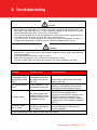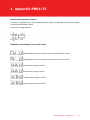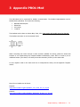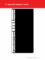
1
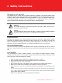
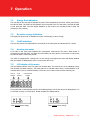
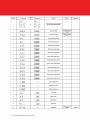
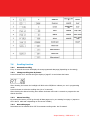
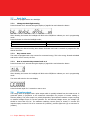
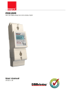
PRO1-S PRO1-2T PRO1-Mb PRO1-Mod PRO 1 Series MID DIN rail single phase two wire energy meter User Manual Product version: 1.12 © 2014 Inepro B.V. All rights reserved 1 Index 2 Safety instructions .........................................................................................................3 3 Foreword ........................................................................................................................5 4 Certificates .....................................................................................................................6 5 Specifications .................................................................................................................7 5.1 Performance criteria .........................................................................................7 5.2 Basic errors......................................................................................................7 5.3 Infra-red specification .......................................................................................8 5.4 M-bus communication specifications (PRO-Mb only) ............................................ 8 5.5 RS485 communication specifications (PRO-Mod only) .......................................... 8 6 5.6 Dimensions ......................................................................................................8 Installation .....................................................................................................................9 7 Operation ......................................................................................................................11 8 7.1 Energy flow indication..................................................................................... 11 7.2 Re-active energy indication ............................................................................. 11 7.3 Tariff indication .............................................................................................. 11 7.4 Reading the meter.......................................................................................... 11 7.5 LCD display of the meter ................................................................................. 11 7.6 Scrolling function............................................................................................ 13 7.7 Back light ...................................................................................................... 14 7.8 S0 pulse output .............................................................................................. 14 7.9 Setting the total (combined) energy calculation................................................. 15 7.10 Communicating via the M-bus output(PRO1-Mb only) ........................................ 15 7.11 Communicating via the Modbus output(PRO1-Mod only) .................................... 16 Troubleshooting ...........................................................................................................17 8.1 List of errors in display.................................................................................... 18 8.2 Technical support ........................................................................................... 18 1 Appendix PRO1-2T .......................................................................................................19 2 Appendix PRO1-Mb ......................................................................................................20 3 Appendix PRO1-Mod.....................................................................................................21 4 Appendix Infra-Red PC software..................................................................................22 5 Appendix Registry matrix .............................................................................................23 2 – Inepro Metering – PRO Series 1 2 Safety instructions Information for your own safety This manual does not contain all of the safety measures for operation of this meter because special operating conditions, local code requirements or local regulations may necessitate further measures. However, it does contain information which must be adhered to for your own personal safety and to avoid material damage. This information is highlighted by a warning triangle with an exclamation mark or a lightning bolt depending on the degree of actual or potential danger: Warning This means that failure to observe the instruction can result in death, serious injury or considerable material damage. Caution This means hazard of electric shock and failure to take the necessary safety precautions will result in death, serious injury or considerable material damage. Qualified personnel Installation and operation of the device described in this manual may only be performed by qualified personnel. Only people that are authorized to install, connect and use this device, who have the proper knowledge about labeling and grounding electrical equipment and circuits and can do so in accordance with local (safety)regulations, are considered qualified personnel in this manual. Use for the intended purpose This device may only be used for the application cases specified in the catalog and the user manual and only in connection with devices and components recommended and approved by Inepro Metering B.V. Proper handling The prerequisites for perfect, reliable operation of the product are proper transport, storage, installation and connection, as well as proper operation and maintenance. During its operation certain parts of the meter might carry dangerous voltages. Only use insulated tools suitable for the voltages this meter is used for. Do not connect while the circuit is connected to a power or current source. Only place the meter in a dry environment. Do not mount the meter in an explosive area or exposed to dust, mildew and/or insects. Make sure the used wires are suitable for the maximum current of this meter. Make sure the AC wires are connected correctly before activating the current/voltage to the meter. Do not touch the meter’s connection clamps directly with your bare hands, with metal, blank wire or other conducting material as you will risk an electric shock that could cause possible injury, serious injury or death. Make sure the protection covers are replaced after installation. Inepro Metering – PRO Series 1 – 3 Maintenance and repair of the meter should only be carried out by qualified personnel. Never break any seals (if present on this meter) to open the front cover as this might influence the functionality or accuracy of the meter, and will void all warranty. Do not drop, or allow physical impact to the meteras there are high precision components inside that may break and affect the meter measurement negatively. All clamps should be properly tightened. Make sure the wires fit properly in the connection clamps. If the wires are too thin it will cause a bad contact which can spark causing damage to the meter and its surroundings. Exclusion of liability We have checked the contents of this manual and every effort has been made to ensure that the descriptions are as accurate as possible.However, deviations from the description cannot be completely ruled out, so that no liability can be accepted for any errors or omissions in the information given. The data in this manual are checked regularly and the necessary corrections will be included in subsequent editions. If you have any suggestions, please do not hesitate to contact us. Subject to technical modifications without notice. Copyright Copyright Inepro Metering August 2011. It is prohibited to pass on or copy this document or to use or disclose its contents without express permission of Inepro Metering BV. Any duplication is a violation of the law and subject to criminal and civil penalties. All rights reserved, particularly for pending or approved patent awards or registered trademarks. 4 – Inepro Metering – PRO Series 1 3 Foreword Thank you for purchasing this energy meter. Inepro has a wide product range of devices. We have introduced a large number of energy meters on the market suitable for 110V AC to 400V AC (50 or 60Hz). Besides the normal energy meters we also developed our own pre-paid meters with chip card, chip card re-loaders and a complete PC management control system. For more information on other products please contact our sales department at [email protected] or visit our website at www.ineprometering.com. Although we produce this device according to international standards and our quality inspection is very accurate it’s still possible that this device shows a defect or failure for which we do apologize. Under normal conditions your product should give you years of trouble free operation. In case there is a problem with the energy meter you should contact your distributor immediately. Most of our energy meters are sealed with a special seal. Once this seal is broken there is no possibility to claim any warranty. Therefore NEVER open an energy meter or break the seal of the device. The limited warranty is 5 years after production date, divided into various periods., after production, and only valid for production faults. Inepro Metering – PRO Series 1 – 5 4 Certificates 6 – Inepro Metering – PRO Series 1 5 Specifications Casing Nominal voltage (Un) Operational voltage Insulation capabilities: - AC voltage withstand - Impulse voltage withstand Basic current (Ib) Maximum rated current (Imax) Operational current range Overcurrent withstand Operational frequency range Internal power consumption Test output flash rate (RED LED) Pulse output rate Pulse width - ≤ 5625W - > 5625W Data store 5.1 4KV for 1 minute 6KV – 1.2µS waveform 5A 45A 0.4%Ib-Imax 30Imax for 0.01s 50Hz ±10% ≤2W/Phase - ≤10VA/Phase 10.000 imp/kWh 10.000, 2.000, 1.000, 100, 10, 1, 0.1 or 0.01 imp/kWh 32ms 11.2ms The data can be stored for more than 10 years without power Performance criteria Operating humidity Storage humidity Operating temperature Storage temperature International standard Accuracy class Protection against penetration of dust and water Insulating encased meter of protective class 5.2 PC flame resistant plastic 230V AC 195-253VAC ≤ 75% ≤ 95% -25°C - +55°C -30°C- +70°C EN50470-1/3 B (=1% accuracy) IP51 II Basic errors 0.05Ib 0.1Ib 0.1Ib - Imax 0.2Ib - Imax Cosφ = 1 Cosφ = 0.5L Cosφ= 0.8C Cosφ = 1 Cosφ = 0.5L Cosφ = 0.8C ±1.5% ±1.5% ±1.5% ±1.0% ±1.0% ±1.0% Inepro Metering – PRO Series 1 – 7 5.3 Infra-red specification Infrared wavelengths Communication distance Protocol 5.4 900- 1000nm Direct contact IEC62056-21:2002 (IEC1107) M-bus communication specifications (PRO-Mb only) Bus type baud rate Range Downlink signal Uplink signal Cable Protocol Max. number of meters M-bus 300, 600, 1200, 2400, 4800 and 9600 (default) ≤1000m 64PCS* Master to slave,Voltage modulation Slave to master,Current modulation JYSTY (n×2×0.8) EN13757-3 64* *Note that the maximum number of meters is dependent on the converter, baudrate (the higher the baudrate the smaller the number of meters which can be used) and the circumstances under which the meters are installed. 5.5 RS485 communication specifications (PRO-Mod only) Bus type Protocol Baud rate Address range Maximum bus load Range 5.6 RS485 MODBUS RTU with 16 bit CRC 1200, 2400, 4800, 9600 (default) 0-247 user settable 60 meters per bus 1000m Dimensions Height without protection cover Height Width Depth Max diameter power connection clamps Weight 8 – Inepro Metering – PRO Series 1 90 mm 117 mm 17.5 mm 63 mm 10 mm2 (Solid copper) 0.08 Kg (net) 6 Installation CAUTION Turn off and if possible lock all sources supplying the energy meter and the equipment that is connected to it before working on it. Always use a properly rated voltage sensing device to confirm that power is off. WARNING The installation should be performed by qualified personnel familiar with applicable codes and regulations. Use insulated tools to install the device. A fuse, thermal cut-off or single-pole circuit breaker should be fitted on the supply line and not on the neutral line. The connecting wire, connecting the device to the outside circuit, should be sized in accordance with local regulations for the maximum amount of the current breaker or other overcurrent protection devices used in the circuit. An external switch or a circuit-breaker should be installed on the supply wires, which will be used to disconnect the meter and the device supplying energy. It is recommended that this switch or circuit-breaker is placed near the meter because that is more convenient for the operator. The switch or circuit-breaker should comply with the specifications of the building’s electrical design and all local regulations. An external fuse or thermal cut-off used as an overcurrent protection device for the meter must be installed on the supply side wires. It’s recommended that this protection device is also placed near the meter for the convenience of the operator. The overcurrent protection device should comply with the specifications of the building’s electrical design and all local regulations. This meter can be installed indoor, or outdoor enclosed in a meter box which is sufficiently protected, in accordance with local codes and regulations. To prevent tampering, an enclosure with a lock or a similar device can be used. The meter has to be installed against a fire resistant wall. The meter has to be installed in a well-ventilated and dry place. The meter has to be installed in a protective box if the meter is exposed to dust or other contaminants. The meter can be installed and used after being tested and can be sealed afterwards. The device can be installed on a 35mm DIN rail. The meter should be installed on a location where the meter can be read easily. In case the meter is installed in an area with frequent surges for example due to thunderstorms, welding machines, inverters etc, the meter is required to be protected with a Surge Protection Device. The device should be sealed immediately after installing it in order to prevent tampering Inepro Metering – PRO Series 1 – 9 Connection of the wires should be done in accordance with the connection diagram as shown below: 1 3 4 6 20 and 21 23 and 24 phase line in (L-IN) phase line out (L-OUT) neutral line in (N) neutral line out (N) Pulse output contact (S0) PRO1-S PRO1-2T PRO1-Mb PRO1-Mod 10 – Inepro Metering – PRO Series 1 Not in use External tariff input (230V) M-Bus communication contact Modbus communication contact 7 Operation 7.1 Energy flow indication The red LED on the front panel indicates the power flow measured by the meter. When power flows, the LED will flash. The faster the LED flashes, the more power flows. For this meter, the LED will flash 10.000 times per kWh. The first display indication of the meter in the scrolling mode is either FW (forward) or RV (reverse) 7.2 Re-active energy indication The dispay will show Kvarh to indicate the meter is measuring re-active energy. 7.3 Tariff indication The LCD will show a dot underneath the word tariff on the name plate to indicate tariff 2 is active 7.4 Reading the meter A red LED on the front panel indicates the consumption measured by the meter. When power is consumed, the LED will flash. The faster the LED flashes, the more power is consumed. For this meter, the LED will flash 10.000 times per kW. The meter is equipped with a 6 digit LCD. For the energy consumption the meter will display 9999.99 kWh and switch to 99999.9 kWh when over this value and so on. 7.5 LCD display of the meter The LCD display has two rows. The upper row contains dots. The most left one is for indicating energy flow direction (forward/ reverse). The most right one is will flash when there is communication to an external device (only on selected models). The lower row is used to show al other metering info. Reverse indicator Tariff indicator Communication indicator This means that certain displays have the same abbreviations, but the dot above will distinguish if it is for forward (no dot) or reverse (dot). Please compare the displays below: Total forward active energy Total reverse active energy Inepro Metering – PRO Series 1 – 11 12 – Inepro Metering – PRO Series 1 7.6 Scrolling function 7.6.1 Automatic scrolling Every 10 seconds the meter will display the next programmed data page (depending on the setting) 7.6.2 Change scrolling time by button Press the button for 5 seconds during the display of page RT 00 and release the button After releasing the button the backlight will blink twice OFF/ON to indicate you are in programming mode. Press the button to select the scrolling time (01 to 30 seconds) After choosing the desired scrolling time release the button and wait 10 seconds to program the new data in the meter 7.6.3 Manual scrolling By pressing the button you will go through all data pages one by one starting from page 1 (sequence see in above table and is depending on the version of PRO1) 7.6.4 Data table pages Data tables can be selected ON or OFF for automatic scrolling mode. See IR-manual. Inepro Metering – PRO Series 1 – 13 7.7 Back light The meter is equipped with a blue backlight. 7.7.1 Change the back light setting Press the button for 5 seconds during the display of page BL btn and release the button After releasing the button the backlight will blink twice OFF/ON to indicate you are in programming mode. Press the button to select the backlight mode; bl btn Press button to activate light bl off Always OFF bl on Always ON After choosing the desired scrolling time release the button and wait 10 seconds to program the new data in the meter. 7.7.2 Day counter reset The meter is equipped with a day counter for consumed energy. This is the energy forward calculated and can be reset to zero by the user 7.7.3 How to reset the day counter back to 0 Press the button for 5 seconds during the display of page kWh 0 and release the button After releasing the button the backlight will blink twice OFF/ON to indicate you are in programming mode The meter will switch to the next display: Press the button again for 5 seconds to reset to zero 7.8 S0 pulse output The energy meter is equipped with a pulse output which is optically isolated from the inside circuit. It generates pulses in proportion to the measured consumption for purpose of remote reading or accuracy testing. The pulse output is a polarity dependent, open-collector transistor output requiring an external voltage source for correct operation. For this external voltage source, the voltage (Ui) should be lower than 27V DC. The maximum switching current (Imax) is 100mA. To connect the impulse output, connect 5-27V DC to connector 20 (collector), and the signal wire (S) to connector 21 (emitter). 14 – Inepro Metering – PRO Series 1 pin 20 (collector) pin 21 (emitter) To change the pulse output you need to purchase a IR eye head and PC software from your dealer. Selectable S0 output rates are mentioned in paragraph 6 specifications. 7.9 Setting the total (combined) energy calculation The meter allows you to display the total energy (usage) shown on the display in accordance to different calculation methods. indicating that the total energy is the sum of forward + reverse To change the calculation method used, please use the infra-red eye, which can be bought separately and software which can be downloaded via the website of Inepro. On how to use the infra-red eye to read out values and change settings, a separate manual is available. For this, please contact your local distributor or Inepro Metering bv. You can use the following calculation methods for total energy as follows: Code Total (active) energy C-01 C-04 C-05 C-06 C-09 C-10 Forward only Reverse only Forward + Reverse Reverse – Forward Forward – Reverse Forward – Reverse 7.10 Communicating via the M-bus output(PRO1-Mb only) The meter is equipped with an M-bus port, the data can be read out via this port. The communication protocol conforms to the EN13757-3 standard. The meter can communicate with your PC. In order to read out the meter registers first install and configure the PC software. Use an M-bus level converter to connect the PC and the meter. The cable should be connected to terminals 23 and 24. The default communication adress of the meter is 001. Note: PC software is available at request. Inepro Metering – PRO Series 1 – 15 7.11 Communicating via the Modbus output(PRO1-Mod only) The meter can communicate with your PC. In order to read out the meter registers first install and configure the PC software. Use an RS485 level converter to connect the PC and the meter. The cable should be connected to terminals 23 and 24. The default communication adress of the meter is 001. Note: PC software is available at request. 16 – Inepro Metering – PRO Series 1 8 Troubleshooting CAUTION During repair and maintenance, do not touch the meter connecting clamps directly with your bare hands, with metal, blank wire or other conducting material as that will cause an electric shock and possibly cause injury, serious injury or even death. Turn off and if possible lock all sources supplying the energy meter and the equipment that is connected to it before opening the protection cover and working on it. Turn off and lock all power supply to the energy meter and the equipment to which it is installed before opening the protection cover to prevent the hazard of electric shock. WARNING Maintenance or repair should only be performed by qualified personnel familiar with applicable codes and regulations. Use insulated tools to maintain or repair the meter. Make sure the protection cover is in place after maintenance or repair. The case is sealed, failure to observe this instruction can result in damage to the meter. Problem Possible cause Check/Solution The red consumption LED is not flashing (PULSE LED). There is no load connected to the meter. The load on the line is very low. Connect a load to the meter. The register doesn’t count. There is almost no load connected to the meter No pulse output. The pulse output is not supplied with DC power. The pulse output is not connected correctly. The pulse output rate is wrong. Is the correct pulse rate set via the infra red eye and software? Check with an Ohm-meter if the load value is very low. Check if the red consumption LED is flashing. 10.000 flashes of the LED at 100 pulses per kWh equals 0.01kWh. Check the external voltage source (Ui) is 5-27V DC with a voltage meter Check if the connection is correct: the 527V DC should be connected to the collector connection (pin 20+) and the signal wire (S) to the emitter connection (pin 21-). Download or request the software and use the infra red eye which can be bought seperately. If non of the above works, please contact technical support Inepro Metering – PRO Series 1 – 17 8.1 List of errors in display It could be that one the following errors is displayed on the meter: Display shows Kind of errors Measures Err 01 EEPROM error Please contact technical support for a meter replacement. Err 02 Program code checksum error Please contact technical support for a meter replacement 8.2 Technical support For questions about one of our products please contact: - Your local Inepro Metering distributor Email: [email protected] www.ineprometering.com 18 – Inepro Metering – PRO Series 1 1 Appendix PRO1-2T How to switch between T1 and T2 The meter is equipped with 2 tariff functionality which need to be activated by an external voltage connected to the terminals 23/24 This is an AC voltage between Additional LCD readings for the 2 tariff version Indicating that the current energy direction is Forward and T2 is active Indicating that the current energy direction is Reverse and T2 is active Forward active energy for tariff 2 Reverse active energy for tariff 2 Forward reactive energy for tariff 2 Reverse reactive energy for tariff 2 Inepro Metering – PRO Series 1 – 19 2 Appendix PRO1-Mb The PRO1-Mb can be connected for M-Bus communication. The defaults for Mbus communication are: Baudrate 9600 bits/sec 8 data bits even parity 1 stop bit The M-Bus connection is on the terminals 23/24 The secondary addressing is preset to the last 8 digits of the serial number printed on the side of the meter. However this can be changed to a more convenient number through IR or Mbus communication. The baudrate can be lower to values 4800, 2400, 1200, 600 and 300 baud. Data, parity and stop bit cannot be changed. For the registers used in the meter and how to interpreted the data, see the appendix "Register matrix". Although INEPRO does not give support on third party software and hardware, we noticed good experiences with Relay products with our customers. More detailed info on M-Bus can be found: http://www.m-bus.com/mbusdoc/default.php 20 – Inepro Metering – PRO Series 1 3 Appendix PRO1-Mod The PRO1-Mod can be connected for Modbus communication. The Modbus implementation used is Modbus basic (standard). This means the following: Baudrate 9600 bits/sec 8 data bits even parity 1 stop bit The baudrate can be lower to values 4800, 2400, 1200. Data, parity and stopbit cannot be changed. The Modbus connection is on the terminals 23/24 When connecting the meter through a serial converter (RS485) for testing, please be aware that because of not implementing the complete Modbus infrastructure, there will be a need to put an additional resistor (120 ohms/ 0.25 watts) across the terminals (23 & 24) on the meter side. For the registers used in the meter and how to interpreted the data, see the appendix "Register matrix". More info on Modbus can be found: Physical: http://www.modbus.org/docs/Modbus_over_serial_line_V1_02.pdf Protocol: http://www.modbus.org/docs/Modbus_Application_Protocol_V1_1b3.pdf Inepro Metering – PRO Series 1 – 21 4 Appendix Infra-Red PC software All PRO1-series meters are capable to be read out and configured by IR. The standard used is IRDA (IEC62056-21:2002 (IEC1107)). IR converter and accompaning software are sold separately. Please contact your dealer. 22 – Inepro Metering – PRO Series 1 Contents Serial number Meter code Meter ID (Mbus/Modbus) Baud Rate Protocol Version Software Version Hardware Version Meter Amps S0 output rate Combined Code LCD cycle time Voltage Grid Frequency Current Total Active Power Total reactive power Total Apparent Power Power Factor Tariff Total Active Energy T1 Total Active Energy T2 Total Active Energy Forward Active Energy T1 Forward Active Energy T2 Forward Active Energy Reverse Active Energy T1 Reverse Active Energy T2 Reverse Active Energy Total Reactive Energy T1 Total Reactive Energy T2 Total Reactive Energy Forward Reactive Energy T1 Forward Reactive Energy T2 Forward Reactive Energy Reverse Reactive Energy T1 Reverse Reactive Energy T2 Reverse Reactive Energy Register Address 1000 1010 1018 1020 1050 1054 1058 1060 1066 107A 1510 2000 2020 2060 2080 20A0 20C0 20E0 2200 3000 3100 3200 3020 3120 3220 3040 3140 3240 3060 3160 3260 3080 3180 3280 30A0 31A0 32A0 Read Read Read/write Read/write Read Read Read Read Read/write Read/write Read/write Read Read Read Read Read Read Read Read/write Read Read Read Read Read Read Read Read Read Read Read Read Read Read Read Read Read Read Read/Write 04 02 01 01 02 02 02 01 02 01 01 02 02 02 02 02 02 02 01 02 02 02 02 02 02 02 02 02 02 02 02 02 02 02 02 02 02 Datablocks Float Float Float Float Float Float Float Float Float Float Float Float Float Float Float Float Float Float Float Float Float Float Float Float Float Float signed signed signed signed signed signed signed signed - Big Endian (ABCD) signed signed - Big Endian (ABCD) - Big Endian (ABCD) - Big Endian (ABCD) - Big Endian (ABCD) - Big Endian (ABCD) - Big Endian (ABCD) - Big Endian (ABCD) signed - Big Endian (ABCD) - Big Endian (ABCD) - Big Endian (ABCD) - Big Endian (ABCD) - Big Endian (ABCD) - Big Endian (ABCD) - Big Endian (ABCD) - Big Endian (ABCD) - Big Endian (ABCD) - Big Endian (ABCD) - Big Endian (ABCD) - Big Endian (ABCD) - Big Endian (ABCD) - Big Endian (ABCD) - Big Endian (ABCD) - Big Endian (ABCD) - Big Endian (ABCD) - Big Endian (ABCD) HEX response PR O IR R/W R n/a n/a R R R R R/W R/W R/W R R R R R R R n/a R n/a n/a R n/a n/a R n/a n/a R n/a n/a R n/a n/a R n/a n/a S 1PR O IR R/W R n/a n/a R R R R R/W R/W R/W R R R R R R R n/a R R R R R R R R R R R R R R R R R R 2T 1O Mbus R/W R R/W R/W R R R R R/W R/W R/W R R R R R R R R/W R R R R R R R R R R R R R R R R R R PR IR R/W R R/W R/W R R R R R/W R/W R/W R R R R R R R R/W R R R R R R R R R R R R R R R R R R b M 1- IR R/W R R/W R/W R R R R R/W R/W R/W R R R R R R R R/W R R R R R R R R R R R R R R R R R R od M 1- Modbus R/W R R/W R/W R R R R R/W R/W R/W R R R R R R R R/W R R R R R R R R R R R R R R R R R R PR O 01 (t1 saved), 02 (t2 saved), 11 (t1 not saved), 12 (t2 not saved) 10000, 2000, 1000 (default), 100, 10, 1, 0.1, 0.01 01, 04, 05 (default), 06, 09 and 10 0~30 (seconds, 10 seconds default) 001~247 (001 default; 000 broadcast) 9600 (default), 4800, 2400, 1200, 600, 300 Remarks 5 Appendix Registry matrix Inepro Metering – PRO Series 1 – 23 Open ambitions 24 – Inepro Metering – PRO Series 1