1
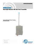
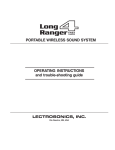
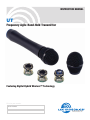
INSTRUCTION MANUAL
UT
Frequency Agile Hand-Held Transmitter
Featuring Digital Hybrid Wireless™ Technology
Fill in for your records:
Serial Number:
Purchase Date:
Rio Rancho, NM, USA
www.lectrosonics.com
UT
2
LECTROSONICS, INC.
Frequency-Agile Hand-Held Trasmitter
Table of Contents
General Technical Description .............................................................................................................................................................. 4
Introduction ........................................................................................................................................................................................... 4
Digital Hybrid Technology ..................................................................................................................................................................... 4
Digital Signal Processor ....................................................................................................................................................................... 4
Microprocessor, PLL and VCO Circuits ................................................................................................................................................ 4
Compatibility Modes ............................................................................................................................................................................. 5
Pilot Tone Squelch ................................................................................................................................................................................ 5
Wide-Band Deviation ............................................................................................................................................................................ 5
Input Limiter .......................................................................................................................................................................................... 5
Long Battery Life .................................................................................................................................................................................. 5
Frequency Agility .................................................................................................................................................................................. 5
Circulator/Isolator ................................................................................................................................................................................. 5
Antenna ................................................................................................................................................................................................ 5
Microphone Element ............................................................................................................................................................................ 5
Controls and Functions ......................................................................................................................................................................... 6
Power On/Off Switch ............................................................................................................................................................................ 6
Power LED ............................................................................................................................................................................................ 6
Compatibility Modes ............................................................................................................................................................................. 6
Frequency Switches ............................................................................................................................................................................. 7
Audio Level LEDs ................................................................................................................................................................................. 7
Audio Level Control .............................................................................................................................................................................. 7
Locked Mode ........................................................................................................................................................................................ 7
VariMic™ Controls ................................................................................................................................................................................. 8
Bass/Mid/Treble (LO/MID/HI) ................................................................................................................................................................ 8
Control Settings: ............................................................................................................................................................................... 8
Preamp Level Control ........................................................................................................................................................................... 8
Subsonic Noise Filter ........................................................................................................................................................................... 9
Interchangeable Capsules .................................................................................................................................................................... 9
VMO omnidirectional condenser ....................................................................................................................................................... 9
VMC cardioid condenser .................................................................................................................................................................. 9
VMS super-cardioid condenser ........................................................................................................................................................ 9
Changing Capsules ............................................................................................................................................................................. 10
Operating Instructions ........................................................................................................................................................................ 12
Selecting Compatibility Mode ............................................................................................................................................................. 12
Adjusting the Audio Gain .................................................................................................................................................................... 12
Power ON/OFF Switch Function Selection ......................................................................................................................................... 13
Determine Power Switch Function .................................................................................................................................................. 13
Changing Power Switch Function ................................................................................................................................................... 13
Battery Installation ............................................................................................................................................................................... 14
Operating Notes ................................................................................................................................................................................... 15
Adjusting the Transmitter Frequency .................................................................................................................................................. 15
Troubleshooting ................................................................................................................................................................................... 16
Specifications ....................................................................................................................................................................................... 17
Service and Repair ............................................................................................................................................................................... 18
Returning Units for Repair .................................................................................................................................................................. 18
Rio Rancho, NM
3
UT
General Technical Description
Introduction
The UT Digital Hybrid Wireless™ handheld transmitter
uses state-of-the-art wireless technology with a highpowered 100mW RF output and a unique microphone
capsule arrangement. The VariMic™ preamp allows the
user to custom-tailor the microphone’s response to suit
the application.
Three capsules are available for this transmitter: a
cardioid condenser, an omni condenser and a supercardioid condenser. Each capsule assembly comes
complete with the VariMic™ preamp.
In addition to providing peerless audio quality in native
400 Series mode, the Digital Hybrid Wireless™ technology in the UT transmitter allows compatibility with a
wide range of receiver types, including Lectrosonics 100
and 200 series and IFB. The UT is also compatible with
receivers from other manufacturers. Contact
Lectrosonics for details.
Digital Hybrid Technology
All wireless links suffer from channel noise to some
degree and all wireless microphone systems seek to
minimize the impact of that noise on the desired signal.
Conventional analog systems use compandors for
enhanced dynamic range, at the cost of subtle artifacts
(known as “pumping” and “breathing”). Wholly digital
systems defeat the noise by sending the audio information in digital form, at the cost of some combination of
power, bandwidth and resistance to interference.
The Lectrosonics Digital Hybrid Wireless™ system
(hereafter called Digital Hybrid) overcomes channel
noise in a dramatically new way, digitally encoding the
audio in the transmitter and decoding it in the receiver,
yet still sending the encoded information via an analog
FM wireless link. This proprietary algorithm is not a
digital implementation of an analog compandor but a
technique which can be accomplished only in the digital
domain, even though the inputs and outputs are analog
signals.
Because it uses an analog FM link, the Digital Hybrid
enjoys all the benefits of conventional FM wireless
systems, such as excellent range, efficient use of RF
spectrum, and long battery life. However, unlike conventional FM systems, the Digital Hybrid has done away
with the analog compandor and its artifacts.
Digital Signal Processor
The DSP encodes the digitized audio from the A-D
converter and adds an ultrasonic pilot tone to control
the receiver's squelch (only in 400 Series, 200 Series
and IFB compatibility modes with the pilot tone enabled
– see Pilot Tone Squelch). It also controls the input
limiter and audio metering.
Microprocessor, PLL and VCO Circuits
An 8-bit microprocessor monitors numerous internal
signals. It also drives the Modulation LEDs, controls the
pilot tone and operates the PLL/VCO circuits.
UT Block Diagram
4
LECTROSONICS, INC.
Frequency-Agile Hand-Held Trasmitter
Compatibility Modes
The transmitter was designed to operate with
Lectrosonics Digital Hybrid Wireless™ receivers and
will yield the best performance when doing so. However, due to the flexibility of digital signal processing, it
is also able to operate with Lectrosonics 200 Series,
Lectrosonics 100 Series, IFB and certain nonLectrosonics analog receivers in special compatibility
modes. (Contact the Lectrosonics Sales Department
for a complete list of compatible receivers.)
Pilot Tone Squelch
The benefit of the pilot tone squelch system is that the
associated receiver will remain muted until it receives
the pilot tone from the matching transmitter, even if a
strong RF signal is present on the carrier frequency of
the system. All 400 Series transmitters use one of 256
different ultrasonic tones between 25 and 32 kHz to
modulate the carrier to operate the receiver squelch.
The pilot tone frequency is chosen according to which
of the 256 channels has been selected by the frequency switch setting. This ensures that all transmitters
in a system have different pilot tone frequencies so that
even spurious RF from the wrong transmitters can’t
open the receiver squelch.
Wide-Band Deviation
Circulator/Isolator
The RF output circuit includes a one way circulator/
isolator using magnetically polarized ferrite. This device
greatly reduces RF intermodulation produced when
multiple transmitters are used at separations of less
than five feet. It also provides additional RF output
stage protection but is rarely seen in a wireless microphone transmitters due to the considerable expense.
Antenna
The highly efficient antenna uses the lower half of the
printed circuit boards as one radiating element, with the
upper half of the PC boards and the mic capsule as the
other half of the dipole configuration. This allows the
mic to be held in any position, since the user’s hands
have little or no effect on the radiated power.
Microphone Element
The UT handheld transmitter is available with any of
three capsule types: the VMC cardioid condenser, the
VMO omni condenser and the VMS super-cardioid
condenser. All three are mounted with tuned suspensions in order to eliminate handling noise. Each capsule
is also mated with the unique VariMic™ preamp arrangement allowing for custom-tailoring the frequency
response based on application.
The ±75 kHz deviation dramatically improves the
capture ratio, signal to noise ratio and dynamic range of
a wireless system.
Input Limiter
A digitally-controlled limiter and a precise, 16-position
attenuation control allow a very wide range of gain
settings based on the source volume, thus optimizing
the signal-to-noise performance in any situation. The
result is the widest dynamic range of any wireless
condenser microphone today.
Long Battery Life
Switching power supplies throughout the design allow
over 3.5 hours of operation using a single 9 VDC
alkaline battery. (A 9 VDC lithium battery will provide
over 6.5 hours of operation.) The battery contacts are
spring loaded to prevent “rattle” as the unit is handled.
Frequency Agility
The transmitter section uses a synthesized, frequency
selectable main oscillator. The frequency is extremely
stable over a wide temperature range and over time.
Two 16-position rotary switches, located under the
battery door, provide 256 frequencies in 100 kHz steps
over a 26.5 MHz range. This alleviates most carrier
interference problems in mobile or traveling applications.
Rio Rancho, NM
5
UT
Controls and Functions
Power On/Off Switch
Windscreen
A Power On/Off switch located on the outside bottom of
the unit turns the unit on and off. The function of the
Power On/Off Switch can also be changed so it also
operates as an audio mute switch. In this configuration,
the Power LED doubles as a battery status indicator (in
the unmute or On position) and an audio mute/unmute
indicator (in the muted or Off position). (See Operating
Instructions, Power Switch Function Selection.) These
functions are illustrated in the chart below:
If the UT Power On/Off Switch has been configured for
Audio Mute Mode, it is still possible to turn off the
transmitter without removing the battery. This is done
by placing the switch in the On position, then toggling
the switch between the On and Off position three times
in less than five seconds, i.e., On (Starting Position)Off-On-Off-On-Off.
Audio Level Control
Modulation
Level LEDs
Battery
Compartment
Cover
Frequency
Switches
Power LED
Battery
Compartment
Locking ring
(Open Position)
Power On/Off
The user-selected configuration of the Power On/Off
switch is stored in the unit’s memory and persists until
reconfigured by the user.
Function
Power Switch Position
On
Off
Normal, or
Power Mode
Applies Power
to Unit
Turns Unit Off
Audio Mute
Mode
Enables Audio
Mutes Audio
Power LED
Whether in normal, mute or locked mode, the Power
LED will indicate the battery level when the unit is
powered up.
The Power LED indicates the battery status when the
unit is powered up with the Power On/Off switch configured for normal operation. The Power LED glows green
when the battery is good. The color
changes to red when there is about
Power LED
30 minutes of operation left with
the recommended lithium
battery. (An alkaline battery
will have about 20 minutes
of life left.) When the LED
begins to blink red, there
are only a few minutes of
life left in the battery. The
Power LED blinks red for a
short period when the
transmitter is configured
for Normal Mode and the
Power On/Off switch is set
to Off. At the end of the
power off sequence, then
Power On/Off
Switch
Power LED goes out.
6
NOTE: A NiMH battery gives little or no warning
when it is depleted. If you use NiMH batteries in
the UT, we recommend trying fully charged
batteries first, noting the length of time that the
batteries will run the unit and in the future use
somewhat less than that time to determine when
the battery needs to be replaced.
When first tinstalled, a weak battery will sometimes
cause the Power LED to glow green, but will soon
discharge to the point where the LED will blink red or
shut off completely.
When Power On/Off switch is configured for Audio Mute
Mode, the Power LED indicates battery status when the
switch is set to On. However, when the Power On/Off
swtich is configured for Audio Mute Mode and set to Off,
the Power LED will slowly double blink green to indicate
that the unit’s audio is muted. (See Operating Instructions, Power Switch Function Selection.)
Compatibility Modes
The Power LED is used to indicate Compatibility Mode.
To identify the current Compatibility Mode, as part of
the powerup sequence, the Power LED will blink:
• Once for 100 Series mode
• Two times for 200 Series mode
• Three times for Mode 3*
• Four times for 400 Series mode
• Five times for IFB Series mode
*This mode works with analog receivers from other
manufacturers. Contact Lectrosonics for a complete list
of non-Lectrosonics compatible receivers.
LECTROSONICS, INC.
Frequency-Agile Hand-Held Trasmitter
Frequency Switches
Coarse Fine
Modulation LEDs
-20 -10
Locked Mode
The UT can be placed in a locked mode where the
Power switch and the Frequency Switches are disabled.
This protects the unit from accidental power-off or
misadjustment after it has been prepared for use.
To enter locked mode, toggle the Power switch off then
on again rapidly three times. The sequence must start
with the Power Switch in the On position. Set the Power
Switch to On, then initiate the Locked Mode sequence,
i.e., Off-On-Off-On-Off-On). Each toggle must take no
longer than two seconds and there cannot be more
than ten seconds between toggles.
Audio Level
Frequency Switches
Two 16-position rotary switches (located under the
battery door) adjust the operating frequency of the
transmitter. The Coarse switch adjusts the frequency in
1.6 MHz steps and the Fine switch adjusts the frequency in 100 kHz steps.
Audio Level LEDs
The two bicolor Modulation LEDs (located under the
Battery Compartment Cover) provide a visual indication
of the audio signal level to the microphone. These
LEDs can glow either red or green to indicate modulation levels as shown in the following chart.
Signal Level
-20 LED
-10 LED
Less than -20 dB
Off
Off
-20 dB to -10 dB
Green
Off
-10 dB to +0 dB
Green
Green
+0 dB to +10 dB
Red
Green
Greater than +10 dB
Red
Red
During the first two toggles, the Power LED will behave
normally, blinking slowly red while the switch is in the off
position to warn that the power will go off, then returning to normal battery status indication when the switch
is set to On again. After the third toggle, the Power LED
will go out briefly, then blink the code that indicates the
current Compatibility Mode, just as it does when the
unit is first powered on. The Power LED going out
briefly followed by this blinking code serves as a
confirmation that the switches are now locked.
Locked Mode can only be cleared by removing the
battery. Note that since removing the battery bypasses
the normal delayed power-off circuit, it may cause noise
at the receiver.
Audio Level Control
The Audio Level Control (under the Battery Compartment Cover) is used to adjust the audio input level for
proper modulation.
Rio Rancho, NM
7
UT
VariMic™ Controls
Caution: Due to the high RF levels surrounding
the transmitter, the sound of the VariMicTM capsule
may be temporarily affected if the metal
windscreen is not in place. Always make the final
decision about sound balance and quality with the
windscreen in place.
Note: The attenuator should not be used as a level
control. The Audio Level control inside the battery
compartment is the main level control. Adjust the
Preamp Level Control only when the Audio Level
control is turned completely down and more
headroom is still needed. Be sure to set the
Preamp Level Control back to its original setting
for normal operation.
The VariMicTM head includes adjustments for Bass (LO),
Midrange (MID) and Treble (HI) response. There is also
an attenuation adjustment to provide up to 15 dB of
additional headroom if needed.
Bass/Mid/Treble (LO/MID/HI)
The bass and treble controls will boost/cut by up to 8 dB
while the Mid control will boost/cut up to 6 dB. These
controls operate as standard tone controls: A counterclockwise adjustment cuts the response in that band
and a clockwise adjustment boosts the response.
These controls can be accessed by removing the
windscreen. To remove the windscreen, grasp the body
of the transmitter in one hand and the windscreen in the
other hand. Carefully unscrew the windscreen counterclockwise until it comes off. Then, carefully slide the
windscreen past the mic element.
Control Settings:
•
Set flat, the response comes directly from the
capsule, without alteration.
•
Bass cut gives a dry but highly intelligible sound.
Crisp.
Bass (LO)
Mid (MID)
Treble (HI)
VariMic Tone Control Range
+10
•
Bass boost “fattens” the sound but is very listenable. Does not get midbass boomy.
•
Midrange cut sounds very smooth. Almost a
“crooner” quality. A sweet sound.
•
Midrange boost is likely to be useful in a system
that is midrange shy.
•
Treble cut has a “mellow” sound. These capsules
have a solid high end so a little cut does not ruin
the response.
•
Boost
Treble
Bass
Midrange
Bass
Midrange
+5
0dB
-5
Treble
Cut
-10
10Hz
100Hz
10KHz
1KHz
Treble boost might be fine on some sound systems.
The sound doesn’t get harsh (showing that the
response was smooth) but sibilants may be excessive. Should be used in moderation.
Preamp Level Control
The VariMicTM head includes an attenuator to provide an
additional 15 dB of headroom when needed. The
attenuator should only be used when the normal Audio
Level control is already turned down as far as it will go
and the signal through the mic is still too high. The
attenuator control is a 16-position switch marked “0”
through “F.” “F” is minimum attenuation. “0” is maximum
attenuation. For the maximum amount of headroom,
set the switch to “0.”
Preamp Level Control
(Shown set to “F”)
8
LECTROSONICS, INC.
Frequency-Agile Hand-Held Trasmitter
Subsonic Noise Filter
In addition to the tone controls, the UT also has a builtin subsonic noise (or high pass) filter. This filter is fixed
and cannot be adjusted or defeated. Low frequency
noise is much more of a problem with wireless microphones than with conventional microphones. With a
conventional mic, low frequency wind noise, breath
thumps or handling rumble can be filtered out at the
control board before the noise causes problems with
the following electronics or speaker systems. However,
with a wireless microphone, the electronics that will be
overdriven are in the microphone itself. Filtering at the
control board is too late. To solve this problem, the
VariMicTM has a subsonic noise filter that is so sharp
that it can remove low frequency noise without affecting
any wanted vocals. It consists of a 90 dB per octave
filter circuit to sharply remove low frequency noise
below 75 Hz without affecting vocal fundamentals. (For
reference, the lowest operatic bass voice fundamental
is 82 Hz.)
Interchangeable Capsules
Any of these capsules may be included with the UT as
a standard option, or they can be ordered separately:
VMO omnidirectional condenser
The omni capsule is perfect when the talent may need
to be off-axis, such as in an interview situation. Also,
omni capsules by nature are much more immune to
handling, popping and wind noise than directional
microphones. In addition, this capsule has slightly
higher sensitivity than the VMC cardioid capsule.
VMC cardioid condenser
This element has excellent frequency and transient
response rivaling the top condenser performance
microphones on the market. The pickup pattern is a
standard cardioid with exemplary off-axis response,
allowing the talent to move around the microphone
without a change in tone. The extended high-frequency
response produces an open, clean sound with excellent
intelligibility.
VMS super-cardioid condenser
In applications where maximum gain before feedback is
required, the VMS capsule is the right choice. With its
nearly perfect super-cardioid pattern, the AKG C5900
capsule rejects sounds from the direct rear and rear
sides, while providing a generous frontal “live” area. The
VMS is slightly lower in sensitivity when compared to
the VMC.
Rio Rancho, NM
9
UT
Changing Capsules
1) Remove windscreen
2) Loosen and remove the
two socket head bolts
that attach the capsule
to the microphone body
3) Lift capsule assembly
4) Disconnect 3-pin
connector
Caution: Avoid damaging
the coiled wire under the
capsule.
5) Connect new capsule
10
6) Set new capsule assembly
to align the holes for the
socket head bolts
LECTROSONICS, INC.
Frequency-Agile Hand-Held Trasmitter
7) Insert and tighten both
socket head bolts
8) Replace windscreen
Note: Older units may have
phillips head bolts. Please use
the supplied socket head bolts to
install the new capsule.
Rio Rancho, NM
11
UT
Operating Instructions
Selecting Compatibility Mode
4) Rapidly toggle the Power Switch Off and On.
This transmitter is capable of working with Lectrosonics
400 Series Digital Hybrid Wireless™, 200 Series, 100
Series, and some analog wireless receivers from other
manufacturers. (Contact Lectrosonics for details.) The
transmitter must be set for compatibility with the matching receiver, which is easily done using the supplied
screwdriver and a battery.
Note: The unit is supplied from the factory
configured as a 400 Series transmitter.
2) Install a good
battery in the
transmitter. Turn
on the transmitter
and observe the
Power LED to
determine the
current Compatibility Mode. The
Power LED will blink:
Power LED
Power Switch
IMPORTANT: When performing the following
steps, The transmitter allows ten seconds to
set the frequency switches before the next
toggle of the power switch. When toggling the
power switch, it is not neccesary to allow the
transmitter to turn off completely. If more than
ten seconds elapse between toggles, the mode
change will not take effect and you must begin
again from step 3.
Frequency Switches
Coarse
Fine
2
3
4
5
9 8 7
6
Set the Frequency Switches to 0,0.
6) Rapidly toggle the Power Switch Off and On.
Observe the Power LED on the bottom panel to
verify the compatibility mode for the unit has
changed. The Power LED will blink the new
compatibility mode. (See Step 2.)
Note: Each time the transmitter is turned on, the
Power LED will confirm the current operating
mode with the number of blinks listed in Step 2.
The mode setting will not change until it is reset
with the procedure listed above.
1) Install a good battery in the transmitter. Move the
Power Switch to On and observe the Power LED. It
should blink the compatibility mode, then glow green.
3) With a small screwdriver (included with your unit),
set the Frequency Switches to “CC” (for Change,
Change).
E
D
C
B
A
1,1
2,2
3,3
4,4
5,5
Adjusting the Audio Gain
• Once for 100 Series mode
• Two times for 200 Series mode
• Three times for mode 3
• Four times for 400 Series mode
• Five times for IFB Series mode
F 0 1
• 100 Series mode:
• 200 Series mode:
• Mode 3:
• 400 Series mode:
• IFB Series mode:
5) Rapidly toggle the Power Switch Off and On.
1) Set the audio output controls for the corresponding
receiver to minimum.
Modulation LEDs
-20 -10
Change the Frequency Switches to one of the
following settings:.
E
D
C
B
A
F 0 1
2
3
4
5
9 8 7
6
2) Set the preamp level attenuator (Refer to “Preamp
Level Control” on page 8).
3) Hold the microphone the way it will be used in
actual operation.
4) While speaking or singing at the same voice level
that will actually be used during the program,
observe the Modulation LEDs. Adjust the Audio
Level control until the –20 dB LED occasionally
flickers red and the -10 dB glows green. (See
Modulation Chart.)
Signal Level
-20 LED
-10 LED
Less than -20 dB
Off
Off
-20 dB to -10 dB
Green
Off
-10 dB to +0 dB
Green
Green
+0 dB to +10 dB
Red
Green
Greater than +10 db
Red
Red
Note: If you find that the Audio Level control is set
to minimum and both Modulation LEDs glow red
sporadically, then it may be necessary to adjust
the Preamp Level Control. This control is located
under the UT’s windscreen. Unscrew the
windscreen and carefully lift it off the top of the
unit. See the VARIMICTM CONTROLS section for
these adjustments. If the Preamp Level Control is
adjusted, be sure to repeat the audio gain
adjustment procedure beginning at step 3.
Audio Level
12
LECTROSONICS, INC.
Frequency-Agile Hand-Held Trasmitter
5) Once the audio gain has been set, the signal
can be sent through the sound system for
overall level adjustments, monitor settings, etc.
Power ON/OFF Switch Function Selection
The Power On/Off switch can be configured as an audio
mute switch. When used as an audio mute switch, the
power switch causes the transmitter’s audio to be
muted when the switch is placed in the Off position.
The Power LED double blinks green to indicate that the
transmitter is in Audio Mute Mode.
In Audio Mute Mode, the transmitter can still be turned
off by starting with the Power On/Off switch in the On
position, then toggling the Power Switch three times
(ending in the Off position) within five seconds to initiate
the power off sequence. The sequence would be:
On (starting position)-Off-On-Off-On-Off.
Audio Mute Mode will persist when the unit is powered
up again, until it is changed with the procedure at right.
Determine Power Switch Function
Use the following procedure to determine the currently
selected function for the Power On/Off Switch.
1) If the transmitter is turned off, set the Power Switch
On and observe the Power LED to confirm that a
good battery is installed.
2) After the power up sequence completes, place the
POWER On/Off switch in the Off position and
observe the Power LED.
Changing Power Switch Function
1) Ensure the Power On/Off switch is in the On
position.
2) With a battery installed, open the Battery Compartment to expose the Frequency Select Switches.
3) With a small screwdriver (included with your unit),
set the Frequency Select Switches to F,F (for
Function, Function).
4) Rapidly toggle the Power On/Off switch off, then on
again.
5) Set the Frequency Select Switches for the desired
configuration from the choices below:
Normal Mode:
1,1
Audio Mute Mode: 2,2
6) Rapidly toggle the Power On/Off switch off, then on
again.
7) Set the Frequency Select Switches to 0,0.
8) Rapidly toggle the Power On/Off switch off, then on
again.
Note: At this time, the power LED will blink the
code for the selected compatibility mode, just as it
does at powerup, as a comfirmation.
9) To confirm the power switch mode, observe the
behavior of the LED while turning off the transmitter. Refer to Step 3 in the previous section (Determine Power Switch Function).
3) If the Power LED slowly double blinks green, the
Power On/Off Switch is in Audio Mute Mode. If the
Power LED fast blinks red then goes out, the Power
Switch is in Normal or Power Mode.
Rio Rancho, NM
13
UT
Battery Installation
The transmitter is powered by a standard alkaline or
lithium 9 Volt battery. Alkaline batteries will provide
about 3.5 hours of operation while the lithium batteries
will operate the transmitter for about 6.5 hours.
Note: The battery status lamp will function normally
only with alkaline or lithium batteries. Standard
zinc-carbon batteries marked “heavy duty” or
“long-lasting” are not adequate. They will provide
only about 30 minutes of operation.
NiMH rechargeable batteries will work, but they run
down quite abruptly. Because of this, using the Power
LED to verify battery status not reliable with NiMH
batteries. However, a number of Lectrosonics receivers
incorporate a Battery Timer function which tracks the
amount of time the transmitter signal is detected (See
your receiver manual to determine if this function is
available.) By using the receiver’s battery timer and
replacing the transmitter battery before the
premeasured time is up, users can minimize potential
loss of audio when NiMH batteries are used.
The battery compartment is located in the lower section
of the transmitter, between the two printed circuit
boards. Follow the steps illustrated to the right to install
a fresh battery.
Note the two differently sized holes in the battery
contact pad inside the Battery Compartment. Insert the
battery so that the large hole in the battery contact pad
will line up with the large contact on the battery. A
spring-loaded plunger in the bottom of the compartment
(opposite the contact pad) secures the battery in place.
14
The battery status is indicated by the Power LED on the
bottom panel. The Power LED glows green when a new
battery is installed, then changes to red as battery
condition deteriorates. It begins blinking red as the
battery nears depletion. Battery status is also displayed
on the front panel LCD of some Lectrosonics receivers.
See the associated receiver manual for further details.
Note: It is possible to insert the battery backwards
and still be able to close the battery door. No
damage will occur but the transmitter will not
operate in this condition.
LECTROSONICS, INC.
Frequency-Agile Hand-Held Trasmitter
Operating Notes
The Audio Level control should not be used to control
the volume of the overall sound system or recorder
levels. This gain adjustment is used to match the
transmitter gain with the user’s voice level and microphone position.
If the audio level is too high — both Modulation
LEDs glow red sporadically. This condition will
reduce the dynamic range of the audio signal.
If the audio level is too low — neither Modulation
LED will glow, or only the -20 LED will glow green.
This condition may cause hiss and noise in the
audio.
Different voices will usually require different settings of
the Audio Level control, so check the Audio Level
settings as each new person uses the UT. If several
different people will be using the same UT and there is
not time to make the adjustment for each individual,
adjust it for the loudest voice.
Adjusting the Transmitter Frequency
If you are experiencing interference from another signal
on your operating frequency, you may need to change
the operating frequency of your system. This is done
through two Frequency Switches located under the
Battery Compartment Cover.
All 400 Series receivers (and a number of earlier
receivers) offer front panel LCDs that indicate the
correct transmitter switch settings, and provide built-in
scanning functions to help locate clear channels. Use
the scanning functions on these receivers to find a clear
channel, then switch both the receiver and transmitter
to the Frequency Select Switch settings indicated in the
receiver’s display.
The R400A model receivers have an autotune function
(SmartTune™) that automatically locates clear operating channels.
If your receiver does not have an autotune or built in
scanning function, manually tune the receiver across its
band and find a frequency where little or no RF activity
is displayed, with the transmitter turned off .
After finding a clear channel, set the transmitter to this
new frequency, then turn it on and make sure the RF
signal is strongly indicated at the receiver. Be sure the
switch settings on the receiver and transmitter are set
exactly the same. If, for example, the 100K switch is
one click above or below the desired frequency, the
receiver will indicate RF, but no audio (or severely
distorted audio) will be produced.
The left switch is for coarse frequency adjustment, and
it increments the operating frequency in 1.6 MHz steps.
The right switch is for fine frequency adjustment and it
increments the operating frequency in 100 kHz steps.
Frequency Switches
Coarse
Fine
Rio Rancho, NM
15
UT
Troubleshooting
SYMPTOM
POSSIBLE CAUSE
UT POWER LED OFF
1) Battery is inserted backwards.
2) Battery is dead, or too low to be used.
UT MODULATION LEDs OFF
1) Audio Level control turned all the way down.
2) Battery is in backwards. Check Power LED.
3) Mic capsule is damaged or malfunctioning.
Contact the factory for repair .
4) Attenuator on VariMic™ preamp board is set for
too much attenuation.
RECEIVER RF INDICATOR OFF
1)
2)
3)
4)
UT not turned on.
Battery is dead or installed backwards
Receiver antenna missing or improperly positioned.
UT and receiver not on same frequency. Check labels on UT and
receiver to be sure they are operating on the same frequency block.
5) Make sure the transmitter and associated frequency switch settings
are in agreement.
6) Operating range is too great.
NO SOUND BUT RECEIVER AUDIO LEVEL METER INDICATES SOUND
1) Receiver audio is muted. (Unmute receiver.)
2) Receiver audio output levels set to low.
3) Receiver audio output is disconnected or cable defective
or miswired.
4) Sound system or recorder input is turned down.
DISTORTED SOUND
1) UT Audio Level control set too high. Speak or sing into the UT and
check the UT Audio Level LEDs and corresponding indicators on the
receiver.
2) Receiver output level may be too high for the sound system or
recorder input.
3) If audio level is all the way down, it may be necessary to increase
attenuation in the capsule. Refer to the “Preamp Level Control”
section on page 8.
3) Excessive wind noise or breath “pops.” Microphone may require
an additional wind screen.
4) UT Frequency Switches set incorrectly.
5) RF feedback getting into VariMicTM mic capsule. Ensure that the
windscreen is present and screwed down snugly.
6) Compatibility Mode mismatch between transmitter and receiver.
HISS AND NOISE -- AUDIBLE DROPOUTS
1)
2)
3)
4)
EXCESSIVE FEEDBACK
1) UT Audio Level control set too high. Check level adjustment,
reduce receiver output level, or both.
2) Microphone too close to speaker system.
3) Move microphone closer to the user’s mouth and lower the
sound system volume.
16
UT Audio Level control set too low.
Receiver antenna missing or obstructed.
Operating range too great.
UT Frequency Switches set incorrectly.
LECTROSONICS, INC.
Frequency-Agile Hand-Held Trasmitter
Specifications
Operating frequencies:
Frequency selection:
Channel Separation:
RF Power output:
Pilot tone:
Frequency stability:
Deviation:
Spurious radiation:
Input limiter:
Gain control range:
Modulation indicators:
Block 21
Block 22
Block 23
537.600 - 563.100
563.200 - 588.700
588.800 - 607.900 and
614.100 - 614.300
Block 24
614.400 - 639.900
Block 25
640.000 - 665.500
Block 26
665.600 - 691.100
Block 27
691.200 - 716.700
Block 28
716.800 - 742.300
Block 29
742.400 - 767.900
256 frequencies in 100 kHz steps
100 kHz
100 mW (nominal)
25 to 32 kHz frequency
(400 Series Compatibility Mode only);
5 kHz deviation
± 0.002%
± 75 kHz (max)
90 dB below carrier
Dual envelope limiter, >30 dB range
43 dB; semilog rotary control
Dual bicolor LEDs indicate modulation
of -20, -10, 0 and +10 dB
referenced to full modulation.
Low frequency roll-off:
Audio frequency response
(overall system):
Controls:
Battery:
Battery Life:
Weight:
Dimensions:
-3 dB @ 70 Hz, 36 dB/octave
80 Hz to 20 kHz (+/- 1 dB)
2 position “OFF-ON” slide Power switch for
noiseless turn on/off operation.
Audio Level Control in Battery Compartment
adjusts audio gain. Two rotary switches in
Battery Compartment adjust transmitter
operating frequency.
Precision compartment auto-adjusts to
accept any known alkaline 9 Volt battery.
3.5 hours (alkaline); 6.5 hours (lithium)
12.4 oz.. with VariMic™ capsule and
lithium battery
9” long x 2.05” diameter at largest point
Emission Designator: 180KF3E
Specifications subject to change without notice.
The FCC requires that the following statement be
included in this manual:
This device complies with FCC radiation exposure
limits as set forth for an uncontrolled environment.
This device should be installed and operated so
that its antenna(s) are not co-located or operating
in conjunction with any other antenna or transmitter.
Rio Rancho, NM
17
UT
Service and Repair
If your system malfunctions, you should attempt to correct or isolate the trouble before concluding that the equipment
needs repair. Make sure you have followed the setup procedure and operating instructions. Check the interconnecting cables and then go through the Troubleshooting section in this manual.
We strongly recommend that you do not try to repair the equipment yourself and do not have the local repair shop
attempt anything other than the simplest repair. If the repair is more complicated than a broken wire or loose connection, send the unit to the factory for repair and service. Don’t attempt to adjust any controls inside the units. Once set
at the factory, the various controls and trimmers do not drift with age or vibration and never require readjustment.
There are no adjustments inside that will make a malfunctioning unit start working.
LECTROSONICS’ Service Department is equipped and staffed to quickly repair your equipment. In-warranty repairs
are made at no charge in accordance with the terms of the warranty. Out-of-warranty repairs are charged at a modest
flat rate plus parts and shipping. Since it takes almost as much time and effort to determine what is wrong as it does
to make the repair, there is a charge for an exact quotation. We will be happy to quote approximate charges by phone
for out-of-warranty repairs.
Returning Units for Repair
For timely service, please follow the steps below:
A. DO NOT return equipment to the factory for repair without first contacting us by letter or by phone. We need to
know the nature of the problem, the model number and the serial number of the equipment. We also need a
phone number where you can be reached 8 A.M. to 4 P.M. (U.S. Mountain Standard Time).
B. After receiving your request, we will issue you a return authorization number (R.A.). This number will help speed
your repair through our receiving and repair departments. The return authorization number must be clearly shown
on the outside of the shipping container.
C. Pack the equipment carefully and ship to us, shipping costs prepaid. If necessary, we can provide you with the
proper packing materials. UPS is usually the best way to ship the units. Heavy units should be “double-boxed” for
safe transport.
D. We also strongly recommend that you insure the equipment, since we cannot be responsible for loss of or damage to equipment that you ship. Of course, we insure the equipment when we ship it back to you.
Mailing address:
Lectrosonics, Inc.
PO Box 15900
Rio Rancho, NM 87174
USA
Shipping address:
Lectrosonics, Inc.
581 Laser Rd.
Rio Rancho, NM 87124
USA
Web:
www.lectrosonics.com
E-mail:
[email protected]
18
Telephone:
(505) 892-4501
(800) 821-1121 Toll-free
(505) 892-6243 Fax
LECTROSONICS, INC.
Frequency-Agile Hand-Held Trasmitter
Rio Rancho, NM
19
LIMITED ONE YEAR WARRANTY
The equipment is warranted for one year from date of purchase against defects in
materials or workmanship provided it was purchased from an authorized dealer. This
warranty does not cover equipment which has been abused or damaged by careless
handling or shipping. This warranty does not apply to used or demonstrator equipment.
Should any defect develop, Lectrosonics, Inc. will, at our option, repair or replace any
defective parts without charge for either parts or labor. If Lectrosonics, Inc. cannot
correct the defect in your equipment, it will be replaced at no charge with a similar new
item. Lectrosonics, Inc. will pay for the cost of returning your equipment to you.
This warranty applies only to items returned to Lectrosonics, Inc. or an authorized
dealer, shipping costs prepaid, within one year from the date of purchase.
This Limited Warranty is governed by the laws of the State of New Mexico. It states the
entire liablility of Lectrosonics Inc. and the entire remedy of the purchaser for any
breach of warranty as outlined above. NEITHER LECTROSONICS, INC. NOR
ANYONE INVOLVED IN THE PRODUCTION OR DELIVERY OF THE EQUIPMENT
SHALL BE LIABLE FOR ANY INDIRECT, SPECIAL, PUNITIVE, CONSEQUENTIAL,
OR INCIDENTAL DAMAGES ARISING OUT OF THE USE OR INABILITY TO USE
THIS EQUIPMENT EVEN IF LECTROSONICS, INC. HAS BEEN ADVISED OF THE
POSSIBILITY OF SUCH DAMAGES. IN NO EVENT SHALL THE LIABILITY OF
LECTROSONICS, INC. EXCEED THE PURCHASE PRICE OF ANY DEFECTIVE
EQUIPMENT.
This warranty gives you specific legal rights. You may have additional legal rights which
vary from state to state.
581 Laser Road NE • Rio Rancho, NM 87124 USA • www.lectrosonics.com
(505) 892-4501 • (800) 821-1121 • fax (505) 892-6243 • [email protected]
March 27, 2006