1
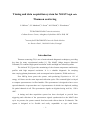
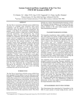
UKAEA FUS 520 EURATOM/UKAEA Fusion Timing and data acquisition system for MAST high rate Thomson scattering S. Shibaev, S.J. Manhood, J. Sousa, M.J. Walsh, J. Waterhouse January 2005 UKAEA EURATOM/UKAEA Fusion Association Culham Science Centre Abingdon Oxfordshire OX14 3DB United Kingdom Telephone: +44 1235 820220 Facsimile: +44 1235 463209 Timing and data acquisition system for MAST high rate Thomson scattering S. Shibaev1, S.J. Manhood1, J. Sousa2. M.J. Walsh1, J. Waterhouse1 1 EURATOM/UKAEA Fusion Association, Culham Science Centre, Abingdon, Oxfordshire OX14 3DB, UK 2 Associação EURATOM/IST Centro de Fusão Nuclear Av. Rovisco Pais1, 1049-001 Lisboa, Portugal Introduction Thomson scattering (TS) is one of main tokamak diagnostic techniques, providing key data for many experimental studies [1]. The MAST (Mega Ampere Spherical Tokamak) TS combines high spatial resolution visible and high rate infrared systems. The infrared TS [2] provides monitoring of the electron temperature and density profiles with high temporal resolution. It is a valuable diagnostic for studying time-varying plasma phenomena, such as transport barrier dynamics, ELMs and so on.. Four NdYag lasers power the system, each producing 50 pulses/s at 1.2 J of energy. All lasers use the same input and collection optics. The scattered light is relayed to compact spectrometers via fibre bundles. The spectrometer is designed to have seven spectral channels. At present there are 14 spectrometers of which 6 are duplexed, making 20 spatial channels in all. The spectrometer signals are digitised using an 8 bit, 1 GS/s ADC. A timing and data acquisition system has been developed to provide laser triggering and collection of the spectrometer signals synchronised to the MAST shot cycle. At present, the system controls four lasers and collects data on 56 channels. The system is designed to be flexible and easily expandable to cope with future -1- improvements, such as additional lasers and data channels. The system has been operating since 2001 (with some modifications) providing reliable, high rate Thomson scattering data. Laser timing The timing sub-system triggers the NdYag lasers synchronously with the MAST shot cycle. Each laser is triggered at a nominal pulse frequency of 50 Hz. For optimum laser performance, a warm up time of up to 2 min is required before each shot. For each laser trigger, the timing system provides two pulses – the first to energise the flash-lamp and the second to fire the laser (by opening a Pockels cell). The delay between these two pulses is configurable, and is gradually reduced during the warm up time. Fig. 1 shows the typical time dependence of the inter-pulse delay – the initial delay being chosen experimentally for optimal laser performance. Flash lamp start Pockels cell laser firing 20 ms delay (microsecond) delay 500 400 300 200 100 0 0 20 40 60 80 100 time (s) Fig. 1. The timing diagram of a single laser trigger and the typical dependence of the laser firing delay. The main timing requirement is to provide synchronous triggering of all lasers. There are three modes of operation – triggering with equal intervals, providing a 200 Hz -2- data rate with four lasers; burst mode, when several lasers are triggered within a short interval; and laser overlapping, to provide higher sensitivity. In overlap mode all the lasers are fired within a 1 ns window. In other modes the laser mutual delays are set in 1 µs steps. The laser timing system has been implemented as a MAST data acquisition unit [3] consisting of a VME workstation and an EPN (Event and Pulse Node) timing module [4]. The EPN module contains eight channels – all used as outputs to provide control of four lasers (two channels per laser, one for triggering the flash-lamp, the other for firing the laser). The EPN output can be programmed as a sequence of static or event frames (pulse sequence) – up to 64k sequences, hence the device configuration is rather complicated. A dedicated software module has therefore been developed to implement limited set of EPN configurations specific for this task, and thus making the configuration more ‘user friendly’. It translates simple records for the device configuration file and for the common MAST “parameter” file into EPN internal configuration parameters. This lets the EPN be configured without reloading the device module, allowing the configuration to be changed between shots by editing the “parameter” file. This file is mounted on a workstation from the central computer and contains only four records listing the start time and full duration of the pulse sequence for each laser. The EPN outputs are logically divided into four pairs. The first channel in each pair controls the flash-lamp triggering, and second the laser firing. Each laser-firing channel independently provides a simple pulse train of 20 ms period, with the start time defining the mutual laser triggering delays and thus the operation mode. When all pairs are set to the same delay, the output pulses are observed to be simultaneous to better than 1 ns. The flash-lamp trigger channel is programmed to output two pulse trains – the first with a period slightly less than 20 ms (typically 100 ns), and the second with a 20 ms period. This provides, at first, a decreasing and then a constant delay between the flash lamp triggering and the laser firing during the warm-up phase. The EPN internal clock is synchronised with the MAST central timing system, so that the laser pulse rate is exactly 50 Hz (20 ms period) in the MAST time-scale. The start time for the pulse sequence is arbitrary with respect to the shot time and is set by the -3- MAST scheduler system before the shot. The start time can be specified in the workstation configuration file to be any time from up to 120 s before the plasma. The laser timing sub-system can be easily expanded by adding additional EPNs, with each controlling up to four lasers. There is one limitation though – the overlap mode with nanosecond synchronisation between lasers can only be implemented for a group of four lasers controlled by the same EPN. EPN modules are synchronised but their internal clocks cannot be simultaneous, so the laser group firing could be separated by up to one EPN time tick (i.e. 100 ns). The EPN also provides a facility for event triggering. An application for this has, however, yet to be identified in the context of the TS system since the lasers cannot be fired at rate higher than 50 Hz and the only possible reaction to an identified event would be an additional delay of subsequent laser pulse. TS data acquisition requirements The TS spectrometer outputs are digitised by 8 bit, 1 GS/s ADCs (Acqiris DC270). At present there are two 6U PXI crates with seven 4-channel ADCs in each. All ADCs in a crate can be connected by an “ASbus” which provides synchronous ADC triggering. The data is captured as a sequence of segments, with the laser pulse triggering each segment. The maximum number of segments depends on the onboard memory size, up to 8000 segments for 8 MB. The delay between segments can be arbitrary, as well as their position with respect to MAST shot. The main requirements for TS data acquisition are: • automatic acquisition of data synchronously with the MAST shot sequence providing correct timing data for each segment in the MAST time-scale; • identification of which laser has triggered the data segment; • graphical data preview for control during operations; • user-friendly configuration of all ADCs (56 channels at present) and operative tuning of ADC when the operating regime changes. -4- The data timing The Acqiris ADC provides precise time stamps that give the interval between data segments. To tie the segment time to MAST time, a simple electronic device was developed which provides gating of the trigger pulses (Fig. 2). Trigger signals coming from the lasers are blocked until the MAST shot trigger. The MAST trigger generates the first trigger input for the ADC and launches all subsequent triggers. So, the first data segment is always triggered by the MAST trigger and, hence, has the correct time in MAST time scale. Laser trigger pulses MAST trigger Data segment trigger Fig. 2. The timing diagram of data segments triggering. The ADC time stamps are registered in picoseconds and rounded to nanoseconds for data timing. The group of ADCs connected by ASbus has a common clock. At present we use two groups, with 7 ADCs in each. The internal clock accuracy is guaranteed to 2 ppm, so the maximum error in measuring the time of first data segment (laser trigger) after MAST trigger is less than 40 ns. This error is proportional to the segment’s number and can exceed 1 µs in 1 s. This error can be easily corrected because the laser trigger period is exactly 20 ms in MAST time scale, provided by EPN synchronisation with the MAST central timing system. This correction could be made automatically, but it is left unchanged to indicate the timing error (the two groups of data have slightly different time values). The error can be corrected in data processing if required. One of ADC channels is dedicated to the laser identification mark. This mark is a sum of pulses generated by lasers. The laser number is coded as a pulse magnitude in geometrical progression. Thus the resulting pulse shows unambiguously which laser, or lasers in overlap mode, trigger the segment. -5- The ADC control program An ADC control program has been developed to meet the requirements of the TS system. The program is implemented as a Windows 2000 application with graphical user interface. It is written in C++ to simplify implementation of future ADC types. At present the program supports two types of Acqiris [5] ADCs, the DC265 and DC270. For maximum performance it doesn’t use the MFC system. The program was developed initially for one crate with 7 ADCs. Then the program was rewritten twice – first to control any number of crates and ADCs, then to implement interface of a new MAST scheduler system. At present, “Acqiris, version 3” is used in operations. Program logic First the program determines the hardware configuration: number of crates, ADCs, and ADCs connected by ASbus. The program creates virtual devices, each device being a number of ADCs connected by ASbus. Usually all ADCs in a crate are connected, that gives one device with 28 channels. The program implies that all ADCs have common trigger. The time stamps are registered by the master ADC in the group connected by ASbus, so all data produced by the group have the same time values. Data times can be slightly different between groups, as mentioned above. During start-up the program tries to connect to MAST scheduler. The result of connecting defines one of two operation modes: “connected” or “disconnected”. In “connected” mode the program creates an acquisition thread on MAST “Trigger” (-20 s) state. The thread waits for the first trigger for a period defined by the “Trigger timeout” time. On receiving the first trigger, the thread waits for the end of acquisition for a period defined by the “Acquisition timeout” time. If at least one data segment is acquired, the program writes data into an IDA file [6] and transfers it to a central archive. The program then waits for the next MAST shot. In “disconnected” mode, the program creates the acquisition thread on pressing the “Run” button and the thread then waits for the first trigger perpetually. The data segments are acquired, saved, and transferred in the same way as for MAST shot. -6- The program contains a manual switch for testing purposes which disconnects the MAST scheduler, logically analogue to unplugging the network cable. All toolbar buttons and configuration dialog boxes are supplied with ToolTips help. There is also a program manual called by F1 key. User interface - main program window The main program window (Fig. 3) contains the menu, the toolbar, the status bar, and the data display. All bars can be switched on or off to provide more space for data display. Fig. 3. The main program window. The toolbar includes only the most frequently used functions. In normal operations the user need only press the “Run” button – the program will acquire and transfer data automatically. The toolbar also contains a “Disconnect” button for running the program independently of MAST, a “Config” button for changing the ADC -7- configuration, and two buttons for unzooming the data display, which is zoomed using the mouse. There is also a small window, which shows the current shot number. The status bar shows the current program mode and state. Two windows of the status bar show the mouse pointer position, the signal (ADC channel) name and the data segment number. The data display shows all acquired data segments in all ADC channels. Its primary goal is to preview data for operative control and to indicate channel overloading. The display therefore shows all data, with overloaded channels indicated by yellow background. Pressing and dragging the mouse button selects a data window to zoom. Fig. 4 shows the data of the same shot with all bars switched off and a zoomed data display. Fig. 4. The main program window - zoomed. When the ADC configuration is changed (range and offset only) the data display is updated to show how the data will look in new configuration. -8- User interface – configuration dialog Fig. 5 shows the configuration dialog where all program settings are collected. There are five groups of settings. MAST settings include: the data file prefix, the MAST trigger time (which is used as a time of first segment’s trigger), the first trigger timeout time (which defines the maximum delay between switching to the MAST “Trigger” state and the hardware trigger) and acquisition time the timeout (which maximum acquire is time all to data segments). Acqiris settings are common to all ADCs. They are: the sampling period, the number of data segments to acquire, the number of samples Fig.5 The configuration dialog. in a segment, and the first sample offset with respect to the segment’s trigger. “Common settings” lets the user increase or decrease all channel ranges with one button click. This is necessary if the plasma density is changed significantly between shots. The sensitivity of some channels should not be changed, so these buttons change range of channels marked as “scaled”. -9- The configuration dialog contains two list boxes, the left ones show all virtual devices (groups of ADCs connected by ASbus). The serial number belongs to the master ADC to which the trigger must be connected. Double clicking on the device item calls the device configuration dialog box, which contains only trigger settings: coupling, level, and input impedance. The right list box shows all channels of the selected virtual device. Double clicking on the channel item calls the channel configuration dialog box, which includes all settings applicable to the ADC channel (Fig. 6). The channel list box shows the channel (signal) name, the range, and whether this channel is “scaled”. Each channel can be switched on or off both in the channel dialog box and in the list box. Fig.6. The channel configuration. Operational issues The control program runs automatically acquiring and transferring data to the central archive when it is connected to MAST central controller. It also correctly handles test shots, with the data being saved to a different file name. At present the MAST shot duration is about 0.5 s, and, hence, the program usually acquires 100 data segments creating a 3.3 MB data file. It takes less than 1 s to get data from ADCs to the computer and about 1 s to transfer it to the central archive. The maximum number of data segments is limited by the ADC on-board memory, 4000 for ADC currently used. So, the maximum shot duration for this system is about 20 s, with 120 MB data file size. The data transferring time rises linearly with the data size. - 10 - The real-time option The period between laser pulses (5 ms) can be used for real-time data processing which could provide real-time temperature and density profiles. This information is of importance for plasma control and real-time processing is the only feasible route for steady state tokamak operations. To implement this option a special ADC control program was developed, AcqirisRT. This program has the same user interface, but different internal structure. ADCs here are programmed to collect one data segment, and the program reads data from all ADCs just after acquiring the segment. The program then restarts all ADCs for the next segment. The real-time program was tested in the same configuration as the working program. It turns out that the minimum data acquisition period is 8 ms – twice the maximum period needed for real-time data processing. The reason for this result is that Acqiris ADC is optimised for collecting a large number of samples and segments reading the channel memory sequentially, and to read data the ADC must be stopped. To implement real-time processing an ADC with a different structure is needed. This could have a smaller on-board data buffer, but it should be adjusted for simultaneous acquisition and data reading. Summary A timing and data acquisition system for the MAST high rate Thomson scattering system has been developed. The system provides triggering of 4 NdYag lasers and acquisition of TS data at a 200 Hz rate. The system operations are synchronised with the MAST shot cycle. The maximum error in the data segment position is less than 40 ns, this error is the same for all data segments after correction. The system has worked faultlessly for several years. It can be easily extended for more lasers. The maximum shot duration with the present ADC is about 20 s, and 40 s with an upgraded ADC. A real-time option for data acquisition and processing has been developed and tested. Its maximum working frequency is 100 Hz. Higher rates may be achieved with a different ADC. - 11 - Acknowledgements This work is funded jointly by the UK Engineering and Physical Sciences Research Council and EURATOM. The EPN fast timer system was developed under collaboration with EURATOM/IST Fusion Association, Lisbon, Portugal. References [1] B. Lloyd et al., Nucl. Fusion 43 (2003), 1665. [2] M. J. Walsh et al., Rev. Sci. Instrum. 74 (2003), 1663. [3] S.J. Manhood, et al, Fusion Eng. Des. 48 (2000), 219. [4] J. Sousa, et al, Fusion Eng. Des. 43 (1999), 407. [5] User manual, family of 8-bit digitizers (2003), http://www.acqiris.com. [6] J. Waterhouse, S.J. Manhood, Fusion Eng. Des. 48 (2000), 187. - 12 -