1
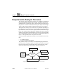
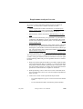
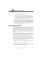
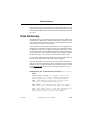
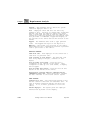
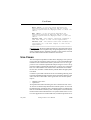
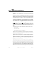
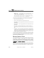
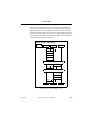
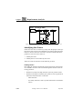
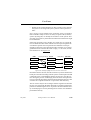
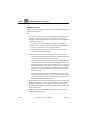
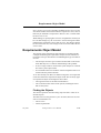
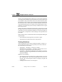
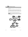
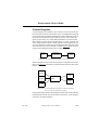
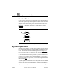
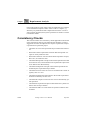
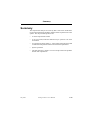
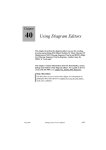
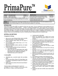
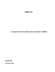
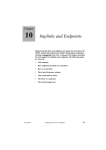
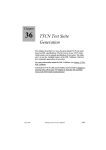
Chapter
71
Requirements Analysis
This chapter gives a thorough description of the different models in
the requirements analysis activity as well as some guidelines on how
to create these models. A recommendation on consistency rules that
are relevant for the models in this activity is also included.
The chapter requires that you are at least reasonable familiar with
the concepts concerning object models as well as the concepts concerning MSC diagrams.
July 2003
Telelogic Tau 4.5 User’s Manual
,um-st1
3697
Chapter
71
Requirements Analysis
Requirements Analysis Overview
The purpose of the requirements analysis is to establish an understanding of the application domain and to capture, formalize, analyze and
validate the user requirements on the system to be built. For this purpose
the system is viewed as a black-box and only the objects and concepts
visible on the system boundary and outside the system are modeled.
The input to this activity can of course be very different depending on
the application, from an extensive requirements specification provided
by a customer to some more or less vague ideas not documented on paper. In any case the result of the activity should be the same: An understanding of the problem domain that the system is to be operating within
and an understanding of the role the system is to fulfill in this environment, i.e. the requirements on the system to be built.
In many cases the requirements analysis can be divided into two activities:
•
•
A problem analysis
A system requirements analysis
The problem analysis concentrates on understanding the problem domain the system is going to operate in, without any reference to the system itself. The system requirements analysis focuses directly on the
functional requirements on the system, viewed as a black box.
Data Dictionary
Req. Use Cases
System Operations
External
textual requirements
Requirements
Analysis
Requirements
Object Model
Internal textual requirements
Figure 627: Overview of the requirements analysis activity
3698
,um-st1
Telelogic Tau 4.5 User’s Manual
July 2003
Requirements Analysis Overview
An overview of the requirements analysis activity is depicted in
Figure 627. As can be seen a number of models are used:
•
Textual requirements model as described in “Textual Requirements” on page 3700. Some requirements are supplied as input to
the activity, others may be produced within the activity.
•
Data dictionary, further described in “Data Dictionary” on page
3701.
•
Use case model, described by text, plain MSCs, or plain MSCs in
combination with HMSCs. The use case model shows the system
and the actors interacting with the system. It is described in “Use
Cases” on page 3703.
•
Requirements object model using object model notation. This model includes both a problem domain model and context diagrams
showing the system and the external actors that interact with the system. The requirements object model is described in “Requirements
Object Model” on page 3711.
•
System operations model, see “System Operations” on page 3716.
The requirements analysis is a highly iterative process where the different tasks creating the different models are iterated over and over again
but the following outline can give some guideline on how to structure
the work:
1. Study any textual requirements that are provided as input and other
sources of information that are available, e.g. read text books about
the problem domain and talk to potential users of the system. This
may also include rewriting (or creating from scratch) the textual requirements to make them more complete or structured.
2. While performing 1 above create a first version of the data dictionary, including lists of actors, use cases and important problem domain concepts.
3. Create a first version of the requirements object model:
July 2003
–
Use context diagrams to give an overview of the actors and the
system.
–
Use an information model to describe the problem domain.
Telelogic Tau 4.5 User’s Manual
,um-st1
3699
Chapter
71
Requirements Analysis
4. Create a first version of the use case model.
–
Review and optimize the list of use cases found so far.
–
Describe the details of the most important use cases as text
and/or MSCs. If the use cases are complex, HMSCs can be used
in combination with plain MSCs. Start with the normal cases
and leave the exceptional cases for the moment.
5. Refine and extend the requirements object model and use case model until the use cases and their exceptions cover a sufficient part of
the requirements. Add state charts to the requirements object model
if the behavior of an object needs to be considered. When needed
use system operations to define the details of the interactions between the actors and the system.
Textual Requirements
Conventional textual requirements are in most development projects an
important input and result of the requirements analysis. In SOMT, the
textual requirements model is simply one or more text documents. It is
however important to include them within the scope of SOMT to get a
possibility to create implinks from them to the other models in SOMT,
and thus make it possible to trace the implementation of the requirements.
The source of the requirements may in some cases be the customers in
which case the textual requirements form one of the inputs to the requirements analysis. In other cases the textual requirements are created
by the development team as part of the requirements analysis.
Non-functional requirements are an example of a type of requirements
that are important to capture, but may be difficult to formulate using the
other models in the requirements analysis. The non-functional requirements may express properties about for example:
•
Performance issues like response time or number of transactions per
second.
•
Reliability like the mean time between failure.
This type of requirements are most easily expressed in natural language
and entered into the textual requirements model.
3700
,um-st1
Telelogic Tau 4.5 User’s Manual
July 2003
Data Dictionary
It is important to not only write down the requirements but also to analyze them. One aspect of this analysis is to mark all important concepts
in the requirements that can be useful later when identifying objects and
use cases.
Data Dictionary
The data dictionary is a textual list of all concepts that are defined during the analysis. The purpose of the data dictionary is to define a vocabulary that is common to all the members of the development team and
to the customers and users of the system.
It is important to notice that the data dictionary is not a separate list of
entities that is unrelated to the other models in the requirements analysis. Rather it can be seen as a different viewpoint on the same set of basic concepts that are used and defined in the use cases and in the requirements object model. For example all domain objects should be added to
the data dictionary as soon as they are defined in the object model.
For each entity defined in the data dictionary at least the name of the entity and a brief explanation of the entity must be supplied.
Note that although the data dictionary is created in the requirements
analysis it can be used during the entire development process and be updated when new concepts are found also in the other activities. The following Example 602 shows a part of a data dictionary for the access
control system.
Example 602: A part of a data dictionary description ––––––––––––––
NOUNS
Access control system - A system to control the
access rights to an office. Unauthorized persons
should not be able to enter without permission.
Card - Each employee working in the office has a
card and a corresponding personal code.
Card reader - The hardware into which the employee
enters the card. The cardreader reads the cardId.
Code - Each employee has a four digit personal code
connected to the card. To enter the office the
employee must type the code on the keypad.
July 2003
Telelogic Tau 4.5 User’s Manual
,um-st1
3701
Chapter
71
Requirements Analysis
Display - The hardware unit by which the system
tells the employee what to do.
Door - Employees enter and exit the office by
opening a door. The door is always kept locked and
unlocks only when the employee enters the office
with a valid card and code or when the employee is
leaving the office by pressing the exit button. Each
door provides a cardreader, keypad and display on
the outside of the office and an exit button on the
inside.
Keypad - The hardware unit used to type personal
codes. The keypad has keys for the digits 0-9.
Employee - The holder of a position in the office.
Every employee has a registered card with a personal
code to get access to the office.
RELATION PHRASES
Card with code - Each employee in the office has a
card with a a personal code.
Code consists of four digits - The personal code
that every employee has got, consists of four
digits.
Door provides local panel - Each door has a
localpanel on the outside of the office. This
localpanel is made up of a card reader, a display
and a keypad.
Door provides exit button - Each door has an exit
button on the inside of the office.
Registerfile contains employee identifications,
cardnumbers and codes - The registerfile contains
the data relevant to the access control system.
VERB PHRASES
Connection is lost - The connection between a door
and the central controller can sometimes fail. In
case of broken connection nobody can enter the
office. It is, however, possible to leave the
office.
Inform employee - The system gives the employee
instructions by means of the display.
3702
,um-st1
Telelogic Tau 4.5 User’s Manual
July 2003
Use Cases
Enter office - A use case which describes the
interaction between an employee and the access
control system when the employee wants to enter the
office.
Exit office - A use case which describes the
interaction between an employee and the access
control system when the employee wants to exit the
office.
Validate card - The central controller validates a
card with respect to info in the registerfile.
Validate code - The central controller validates the
correctness of a code with respect to info in the
registerfile.
––––––––––––––––––––––––––––––––––––––––––––––––––––––––––
In Example 602, the items in data dictionary are categorized into nouns,
relation phrases and verb phrases. By categorizing the items, it may be
easier to find the objects, attributes, operators, actors and use cases and
also the relations between these entities in each model.
Use Cases
The most important problem to tackle when designing a new system is
not to verify the correctness of the system or to get an optimized implementation. None of this matters if the system does not solve the right
problem. User-centered requirements analysis using use cases is an approach to capture requirements from the user’s point of view. The intention is of course that the users will be able to understand and validate
the use cases, and thus confirm that they indeed define the right system
to be built.
Consider a system that controls the access to a building, allowing users
to enter the building through doors that can be opened by entering a card
and a code into a card reader. Some typical use cases for this system
may be:
•
•
“Register a new user”
“Open door”
An important term when discussing use cases is the notion of an “actor”.
An actor is an outside entity that interacts with the system. An actor can
be a human being, a hardware unit, a computer program or anything else
that can communicate with the system. Usually there is also made a distinction between the individual users of a system and the actors. An actor is not supposed to be an individual user, but rather represents one of
July 2003
Telelogic Tau 4.5 User’s Manual
,um-st1
3703
Chapter
71
Requirements Analysis
the different “roles” individual users can play when interacting with the
system.
Each use case describes essentially the possible sequences of events that
take place when one or more actors interact with the system in order to
fulfill the purpose of the use case. Note that the use case does not define
one specific sequence of events, but rather a set of possible sequences.
A use case is thus simply a description, in one format or another, of a
certain way to use the system. It has been found to be a very efficient
way to capture a user’s view of the system and the concept of use cases
is now used in a number of object-oriented methods. The version used
in SOMT is mainly a combination of the original use cases as described
in [18] and the OMT version [19]. A difference is that, as will be seen
below, SOMT puts some more effort in the formalization of the use cases to be able to use them for verification purposes during the object design.
In SOMT the use case model is in practise composed of three parts:
•
A list of actors
•
A list of use cases
•
The collection of use case descriptions
The list of actors should describe all actors that have been identified,
why they use the system (or which service they provide to the system)
and what their responsibilities are.
The list of use cases just gives a one-sentence description of each use
case.
The lists of actors and use cases can either be separate documents or be
a part of the data dictionary. The lists are particularly useful in the beginning of the requirements analysis when trying to identify the most
important use cases and actors.
Two different formats are used to describe use cases in SOMT. One
purely textual format and one format that uses MSC diagrams to define
the use cases. Depending on the application (and the users) one or both
of the notations can be used in a specific project. If the chosen approach
is to describe the use cases by means of MSCs and they turn out to be
very complex, it is possible to use a combination of plain MSCs and
HMSCs to describe them. Most of the things that can be expressed with
3704
,um-st1
Telelogic Tau 4.5 User’s Manual
July 2003
Use Cases
HMSCs can also be expressed by plain MSCs, so it is a matter of taste
if you want to use HMSCs or not. HMSCs have certain advantages, especially if the system is complex:
•
They give a good overview of what is happening in the system and
thereby facilitate understanding of the system behavior.
•
They make it easier to maintain the use case model.
The choice of notation for use cases is a matter of personal taste and the
application at hand. There are four different possibilities:
•
Use only textual use cases.
•
Use only MSC use cases.
•
Give a brief textual description of the use case. Then give a complete formal MSC definition of the use case.
•
Give a complete detailed textual description of the use case, covering all exceptions etc. Then use MSCs to exemplify some of the
more important cases.
Textual Use Cases
The textual format consists essentially of natural language text structured into a number of fields and is easiest introduced with an example.
Consider the Enter building use case for the access control system that
controls the doors of a building. This use case is depicted in
Example 603.
Example 603: Textual description of the Enter building use case––––
Use case name: Enter building
Actors: Regular user, Door
Preconditions: ‘Enter card’ is displayed and doors
are closed and locked
Postconditions: Same as preconditions
Description: A user enters a card into the
cardreader. ‘Enter code’ is displayed on the
display. The user enters his code (4 digits) using
the keyboard. The door is unlocked and ‘Door
unlocked. Please enter.’ is displayed. The user
opens the door, enters the building and closes the
door again. the door is locked again and ‘enter
card’ is displayed.
July 2003
Telelogic Tau 4.5 User’s Manual
,um-st1
3705
Chapter
71
Requirements Analysis
Exceptions: - If the user enters the wrong code then
‘Wrong code’ is flashed for 3 seconds and then
‘enter card’ is displayed.
- If the user does not open the door after it has
been unlocked, then the door is locked again after
30 seconds and ‘Enter card’ is displayed
––––––––––––––––––––––––––––––––––––––––––––––––––––––––––
As can be seen in the example, a use case has the following fields:
•
Name: The name of the use case.
•
Actors: A list of the actors involved in the use case.
•
Preconditions: A list of properties that must be true for this use case
to take place.
•
Postconditions: A list of properties that are true when the use case
is finished.
•
Description: A textual description of the “normal” sequence of
events that describe the interaction between the actors and the system.
•
Exceptions: A list of exceptional interactions that complement the
“normal” flow of events described in the Description field. If an exception leads to different postcondition properties compared to the
“normal” sequence, this should be noted.
As with the textual requirements, it is important to analyze the textual
use cases and clearly mark all important concepts in order to be able to
use them when identifying classes and when performing consistency
checks between the different models.
Message Sequence Charts
The second notation for use cases used in SOMT is Message Sequence
Charts (MSCs). An MSC is a diagram that shows a number of communicating entities (called instances) and the messages that they exchange.
Two MSCs that correspond to the “Enter building” use case are shown
in Figure 628 and Figure 629. Figure 628 describes the normal case and
Figure 629 describes one of the exceptions.
A comment to this use case: There is always a choice of how much to
show in a use case. In this particular example there is of course a choice
whether to show the interaction between the User and the Door that
3706
,um-st1
Telelogic Tau 4.5 User’s Manual
July 2003
Use Cases
does not involve the system. There is of course such an interaction
where the user opens and closes the door. What to do depends on the
purpose of the use case. Is the purpose mainly to describe and understand the problem domain or is the purpose to define the precise requirements on the system? In this use case we have assumed that the purpose
is to define the requirements so the interaction that does not directly involve the system is left out of the MSC.
MSC Enter_building
User
System
Door
Card
Display
’Enter code’
Digit
Digit
Digit
Digit
exc WrongCode
Unlock
Display ’Please enter’
exc DoorNotOpened
Open
Close
Lock
Display
’Enter card’
Figure 628: The “Enter_building” use case
July 2003
Telelogic Tau 4.5 User’s Manual
,um-st1
3707
Chapter
71
Requirements Analysis
MSC WrongCode
User
Display
System
’Wrong code’
t
Display
Door
3s
’Enter card’
Figure 629: The exception “WrongCode” for the “Enter_building” use case
Identifying Use Cases
Often some use cases are found very easily from the purpose of the system, but in some cases it is more difficult. One strategy that works well,
both as a means to find use cases and as a means to check that all important use cases have been found, is:
1. Identify the actors.
2. Identify the use cases needed by each actor.
These two tasks are discussed in the following sections.
Finding Actors
By reading the textual requirements model or discussing with customers, candidates for actors can be found through the answers to the following questions:
3708
•
Which user groups need help from the system to perform a task?
•
Which user groups are needed by the system in order to perform its
functions? These functions can be both:
,um-st1
–
Main functions
–
Secondary functions, such as system maintenance and administration
Telelogic Tau 4.5 User’s Manual
July 2003
Use Cases
•
Which are the external hardware or other systems (if any) that use
the system or are being used by the system in order to perform a
task?
Now, we have a set of possible actors. From this, we have to decide if
these candidates really are actors or if they are parts of the (software)
system. By doing this, we identify the boundaries of the system. This
step does not provide any final solutions and decisions taken here might
be modified later.
If the actor represents a user, perhaps one, single user, try to keep the
level of abstraction that comes with the actor concept. It might be the
case that this specific user can perform some tasks that can be performed by other users and some unique tasks. Therefore, try to distinguish between the roles that the users can play, i.e. the actors, and the
users themselves. See Figure 630.
USER
Can play the role of
ACTOR
Takes part in
USE CASE
Philip
System administrator
Re-boot
Michael
Employee
Enter with code
Ann
Visitor
Outsider entry
Figure 630: Example of difference between users and actors
Document all actors in a list, describe each actor by a name and describe
briefly its role when interacting with the system. The description should
contain the actors’ responsibilities and the way the actor uses the system. During the process of identifying the actors these descriptions are
most conveniently kept in the textual document that lists all actors. This
can either be a separate document or a part of the data dictionary.
The set of actors may be due to changes after having started to describe
the use cases. Especially the MSC diagrams are useful to pinpoint the
problem of determining the actors. In practice this means that the activity of identifying use cases by defining actors and use cases should be
performed iteratively.
July 2003
Telelogic Tau 4.5 User’s Manual
,um-st1
3709
Chapter
71
Requirements Analysis
Finding Use Cases
When you have defined a set of actors, it is time to describe the way they
interact with the system.
Steps:
1. For each actor, find the tasks and functions that he should be able to
perform or tasks which the system needs the actor to perform.
Search the textual requirements for verb phrases, these are possible
candidates for use cases.
–
If possible, make the use cases as complete as possible, i.e.
make one use case of a complex function rather than splitting it
up into several use cases for each sub-function.
–
To begin with, concentrate on the normal cases. Leave the exceptional cases until a later stage.
2. Name the use cases and enter them in a textual list of use cases.
–
The names should be informative and be accompanied with general descriptions of the use case functionality.
–
The naming should be done with care, the description of the use
case should be descriptive and consistent. Example: the use case
that describes when a person leaves deposit items to a recycling
machine could either be named Receive deposit items or Returning deposit items, but the latter is preferable since it is usually
better to give names that reflect the users point of view rather
than the systems.
–
From the list of use cases, try to discard unnecessary use cases.
A use case should represent a set of events that leads to a clear
goal (or in some cases several distinct goals that could be alternative) for the actor or for the system.
3. Describe the use cases using the textual use case format and/or give
a formal description of the use cases using MSCs (combined with
HMSCs if necessary). Use the terms in the requirements object
model and data dictionary as much as possible. Focus to begin with
on the normal cases.
4. Refine the use cases by examining the exceptional cases that are
possible for each use case.
3710
,um-st1
Telelogic Tau 4.5 User’s Manual
July 2003
Requirements Object Model
Now, we have got a view of possible candidates for use cases. It is not
sure that all of these need to be described in separate use cases; some of
them may be modeled as exceptions to other use cases. Consider what
the actor wants to do!
While finding (or specifying) the use cases, it might be the case that you
have to make changes to your set of actors. All actor changes should be
updated in the textual list of actors and use cases. The changes should
be carried out with care, since changes to the set of actors affect the use
cases as well.
Requirements Object Model
The purpose of the requirements object model is to document all the
concepts found during the requirements analysis and the relations between these concepts. The benefits of establishing this type of model are
obvious:
•
The developer and users get a common medium that can be used to
check that they have a common understanding of the problem.
•
It can to a large extent be reused in the system analysis as a foundation of the system object model.
•
It is invaluable when new members of the development team are introduced into the problem domain.
As we have already seen there are different categories of concepts that
can be described in the requirements object model. The two major types
of requirements object model diagrams show either:
•
The logical structure of the data and information
•
The environment and context of the system, including the actors
that use the system.
Finding the Objects
The classical question when discussing object models is: How do we
find the objects?
The final answer to this question is yet to be found, but some obvious
sources of information are:
•
•
July 2003
The use cases
Textual requirements
Telelogic Tau 4.5 User’s Manual
,um-st1
3711
Chapter
71
Requirements Analysis
The use cases are helpful in more than one way. They directly define the
actors that interact with the system and these are of course obvious object candidates. They also describe what is to be entered into the system
and what will come out of the system. This may be physical entities like
the card in the access control system or abstract data like a data unit in
a telecommunication protocol. In either case the entities that are transported in to or out from the system are likely candidates for the requirements object model.
If there exist textual requirements specifications a classical way to find
the objects that may be useful is to study the requirements and note all
nouns that are used. If a particular substantive is used in many places it
may represent a concept that is worth including in the requirements object model.
Other possible sources of information that can be helpful in finding the
objects include:
•
General domain knowledge from text books or experts
•
The physical environment the system will operate in
Finding Relations
After we think that we have found a sufficient number of objects, we
want to relate these objects, or more generally, the classes. There are
three different kinds of relations:
•
•
•
Aggregation – describing a “consists of” relation
Generalization or inheritance – describing a relation where one of
the classes are generalized from the other class(es)
Association – describing how different classes (that are not closely
related by aggregation or generalization) are related by means of information exchange
Relations can be found by
•
•
3712
,um-st1
Searching the textual requirements for “relation phrases”, for example: “card with code”, “the central controller has access to the register file” and “each local panel consists of a display, a keypad, and
a card reader”
Looking in the textual use case description
Telelogic Tau 4.5 User’s Manual
July 2003
Requirements Object Model
In order to increase to readability of the model, name the associations.
If needed, you can also attach role names to each class in an association.
Generalization and aggregation relations can also be named.
Finding Attributes and Operations
Closely related to the associations are the attributes. Attributes are entities (that could be classes of their own) that are considered to be individual for a class.For example: name, address and phone number could
be three different attributes of the class person. This information can be
found in:
•
•
The textual requirements
The use cases
Sometimes it is not easy to decide if an entity should be an attribute of
a class or if it should be a class of its own and have an association to the
other class. If the independent existence of a property is important, then
it should be a class. Consider also possible future changes and extensions, this might also give a reason for making the entity a class of its
own. Example: A card in the access control system could change owner
after a reorganization.
Operations describe functionality of a class. Operations are often used
to modify the attributes of a class. If an operator has features of its own
(attributes that do not have to be known for the whole class), then it
could be modeled as an individual class.
Operations can be found
•
•
•
By looking at the system operations and distributing the responsibilities to several classes
In the textual requirements
In the textual use cases
Information Modeling
The requirements object model forms a description of the problem domain in a graphical way using object model diagrams. The purpose of
the requirements object model is to give an overview of the concepts
used by experts in the problem domain when discussing various aspects
of the problem. Notice that the object models give the overview of the
concepts, more details should be defined in the data dictionary. In the
July 2003
Telelogic Tau 4.5 User’s Manual
,um-st1
3713
Chapter
71
Requirements Analysis
requirements object model the focus is on classes and associations between classes.
Another way to view the requirements object model is that it at least
should describe all concepts that are visible on the “outside” of a system. Note that this does not only include physical entities that a user can
see but also the knowledge the user must have to be able to use the system.
As an example of a small requirements object model consider
Figure 631 that shows a requirements object model for an access control
system that describe the different kinds of persons that are of interest for
the application area, how they relate to cards and codes and the structure
of an office building.
Person
has
Name
Card
CardId
*
Regular_
Guard
linked-with
Operator
Code
User
Digits
Building
1..*
1..*
Office
Entrance
Operator_
Control_
DoorLock
Terminal
Panel
Figure 631: A requirements object model for an access control system
3714
,um-st1
Telelogic Tau 4.5 User’s Manual
July 2003
Requirements Object Model
Context Diagrams
Context diagrams are intended to give a static overview of how the system will interact with its environment. This is accomplished by showing
in a class diagram (if needed exemplified in instance diagrams) what external actors exist that will interact with the system. The context diagrams are obviously very closely linked with the use cases since they
show all types of actors that are defined in the use cases. Actually, one
of the major benefits with the context diagrams is thus that they in one
(or a few) diagrams capture the static information that otherwise is hidden in the use cases. As an example, consider Figure 632 that shows a
simple context diagram for the access control system.
<<actor>>
Door
1..*
<<system>>
AccessControl
*
<<actor>>
User
Figure 632: A context diagram for an access control system
Instance diagrams can be used to show specific configurations or examples as in Figure 633 which show a situation where there are three doors
and two users.
D1: Door
Sys:Access_
D2: Door
A: User
Control
B: User
D3: Door
Figure 633: A context diagram using object instances instead of
classes to show an application example
An important aspect of the context diagrams is that they show where the
borderline between the system and the environment is, event though it
is shown in an abstract fashion.
July 2003
Telelogic Tau 4.5 User’s Manual
,um-st1
3715
Chapter
71
Requirements Analysis
Modeling Behavior
In some cases it is useful to give a description of the internal behavior
of the most important objects that appear in the object model. Due to the
simplicity of the notation State Charts is the preferred notation in the
analysis activities. As an example consider the DoorLock object in
Figure 631. A description of the behavior of this object is shown in
Figure 634.
DoorLock
Locked
Unlock
Lock
Unlocked
Open
Close
DoorOpen
Figure 634: An SDL state machine describing the behavior of the DoorLock object
System Operations
In the use cases a number of events can be found that form the elementary communication means that is used when the system and the actors
interact. For example in the “Enter building” use case in Figure 628
there are several events, e.g. “enter card” and “enter digit”. It is important to understand and document the events that are used in the use cases, since they define the interface between the system and its environment. This can be done in the requirements object model and in the data
dictionary, but sometimes a more detailed definition is useful. This is
the purpose of the system operations, a concept that originates from the
Fusion method [29].
A system operation is a definition of what that system must do to handle
an event. It defines declaratively the behavior of the system as a response to an event in terms of the changes of state and events that are
output or returned. System operations are in SOMT defined using sche-
3716
,um-st1
Telelogic Tau 4.5 User’s Manual
July 2003
System Operations
mata containing structured text. As an example consider the system operation in Example 604 that defines the Enter card operation.
Example 604: A system operation schemata for the enter card
operation ––––––––––––––––––––––––––––––––––––––––––––––––––
Operation: EnterCard
Responsibilites: Informs the system of the fact that
a card has been entered into one of the card readers
Inputs: Card identificatio Card reader
identification
Returns: Enter code’ is displayed
Modified objects: A ‘card’ object,a ‘card reader’
object
Preconditions: The door must be closed
Postconditions: The card identification is stored in
a ‘card’ object associated with the ‘cardReader’
object with an id equal to the card reader
identification that was an input to the operation
––––––––––––––––––––––––––––––––––––––––––––––––––––––––––
The different rows in the schemata has the following meaning:
•
Operation: The name of the system operation (equal to the name of
the event that it handles).
•
Responsibilities: A short description of the operation.
•
Inputs: The data that is supplied as parameters.
•
Returns: The events that are returned to the outside of the system as
a result of the operation.
•
Modified objects: The internal objects that are changed by the operation.
•
Preconditions: Predicates that define when definition of the operation given in this schemata is valid.
•
Postconditions: The postconditions for the operation define how the
state of the system has changed due to the execution of the operation.
Note that in general more than one schemata is needed for each system
operation: one schemata is needed for each possible variant of the preconditions.
The criteria for choosing to use the system operations in addition to the
use cases are based on the estimated complexity of the opera-
July 2003
Telelogic Tau 4.5 User’s Manual
,um-st1
3717
Chapter
71
Requirements Analysis
tions/events in the use cases. If the events are simple there is no need for
a more detailed description of them. If the events are complex, e.g.
when they are parametrized with complex data structures or involve
some complex algorithm, then system operations are useful as a means
to define the details.
Consistency Checks
This section contains some consistency checks applicable to the models
in the requirements analysis. The following list should be viewed as
suggestions and must be adapted to the way the requirements analysis
is performed in a particular project:
3718
•
Check the use cases and requirements object model with actual users.
•
Reread the textual requirements and check that all important concepts are clearly marked as such.
•
Reread the textual use cases and check that all important concepts,
like actors, are marked as such.
•
Check that all important concepts in the textual requirements model
and in the use cases, and all entities in the requirements object model are added to the data dictionary.
•
Check that all important concepts in the textual requirements are
modeled by the requirements object model.
•
Check that all actors in the use cases are modeled in the context diagram(s) and vice versa.
•
Check that all functional requirements in the textual requirements
model are modeled by the use cases.
•
Check that all complex events in the use cases are described by system operations.
•
Check that the requirements object model follows the syntactic/semantic rules for object models.
•
Check that the MSC use cases follow the syntactic/semantic rules
for MSCs.
,um-st1
Telelogic Tau 4.5 User’s Manual
July 2003
Summary
Summary
The requirements analysis is an activity that is focused on understanding and documenting the problem domain and the requirements on the
system. The major models produced are:
July 2003
•
A textual requirements model
•
A use case model, where the different ways a system is to be used
are defined
•
A requirements object model, i.e. a description of the objects needed
to understand the problem domain and external requirements
•
System operations
•
The data dictionary, which is a list of concepts used in the problem
domain and requirements
Telelogic Tau 4.5 User’s Manual
,um-st1
3719
Chapter
71
3720
,um-st1
Requirements Analysis
Telelogic Tau 4.5 User’s Manual
July 2003