Transcript
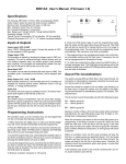
EM11A Dual Channel Event Timer - User’s Manual (Rev. 1)
Specifications
Max. Cycle Time
127 seconds in high resolution mode
254 seconds in low resolution mode
Timing Resolution
1/8 second in high resolution mode
1/4 second in low resolution mode
Unit Cascading
Unlimited number of units can be cascaded.
Max. Relay Load
12A @ 120VAC, 10A @ 240VAC/28VDC
Power Requirement
12V DC, 200 mA
Physical Dimensions
4.25” x 2.75” x 1.6” excluding mounting ears
Inputs & Outputs
Power Jack: VDC
Use a power adaptor capable of providing at least 200 mA at 12V
DC, with a 2.1mm center positive coaxial plug. There is no power
on/off switch.
Power Light: PWR
The power light will be turned on when power is applied.
Trigger Input Terminal: TRG
Depending on how the switch #2 is set, the unit can be triggered by
either making or breaking the connection between the trigger input
and the ground (GND). This can be achieved through various devices such as push buttons, pressure mats, and motion sensors
with dry contacts.
Reset & Cascade Terminal : RST/CAS
This terminal serves as both reset input and cascade output.
The unit can be reset at any time by shorting this terminal to the
ground (GND). The timing cycle, if active at the moment, will be
stopped immediately.
See the Cascading Units section for the cascade function.
Relay Output Terminals: N.C. / N.O. / COM
Both normally closed (N.C.) and normally open (N.O.) contacts are
available for controlling external devices.
Teach-n-LearnTM Programming
The timing cycle can be programmed into the unit with the following
Teach-n-LearnTM procedures:
1. Remove the front cover and press the PROGRAM button. The
PGM light will be turned on.
2. Relay #1 is programmed by pressing/holding the CH#1 button
at the desired moment for the desired duration. The CH1 light will
be lit when relay #1 is on. Use the CH#2 button to program relay
#2. Both relays must be programmed within the same cycle. There
is no limit on the number of times the relay can turn on/off.
3. Press the PROGRAM button again to end the programming.
The timing cycle is now stored in non-volatile memory. The unit
can be re-programmed for thousands of times if necessary.
Switch Settings
Switch #1
OFF = high resolution mode (1/8 second)
ON = low resolution mode (1/4 second)
Switch #2
OFF = normally open trigger
(connect TRG to GND to trigger)
ON = normally closed trigger
(disconnect TRG from GND to trigger)
Timing Resolution
The unit has an internal clock that, when the unit is triggered, starts
ticking once every 1/4 or 1/8 second depending on the resolution.
Relays get turned on/off on the tick only, not between ticks. Therefore, higher resolution means more accuarte timing.
Cascading Units
At the very end of the timing cycle, the RST/CAS terminal turns
into an open collector output for 0.1 second. This pulse can be
used to trigger another unit (which must be configured for normally
open trigger.)