1
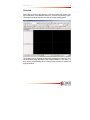
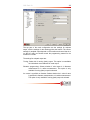
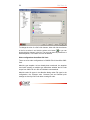
www.cimco-software.com
CIMCO CNC-Calc 2
User Guide
CNC-Calc v2
1
License Information
Information in this document is subject to change without notice and
does not represent a commitment on the part of CIMCO Integration. The
software described in this document may be used or copied only in
accordance with the terms of the license. The purchaser may make one
copy of the software for a backup, but no part of this user manual may
be reproduced, stored in a retrieval system, or transmitted in any form or
by any means electronic or mechanical, including photocopying and
recording for any purpose other than the purchaser’s personal use,
without prior written permission from CIMCO Integration.
TERMS OF USE FOR SOFTWARE
Software: CNC-Calc v2
Version: 2.x.x
Date: October 2004
Copyright © 2004 by CIMCO Integration
Notice:
CIMCO Integration reserves the right to make changes to the CNC-Calc
v2 Software at any time and without notice.
Software License
You have the right to use the number of licenses of the enclosed
program, which you have bought from CIMCO Integration. You may not
distribute copies of the program or related documentation to any persons
or companies. You may not modify the program or related
documentation without the prior written consent of CIMCO Integration.
Disclaimer of all Warranties and Liability
CIMCO Integration makes no warranties, either express or implied, with
respect to the software, its quality, performance, merchantability, or
fitness for any particular purpose. The entire risk as to its quality and
performance is with the buyer. Should the CNC-Calc v2 software prove
defective following its purchase, the buyer (and not CIMCO Integration,
its distributor, or its retailer) assumes the entire cost of all necessary
2
CNC-Calc v2
servicing, repair, of correction and any incidental or consequential
damages. In no event will CIMCO Integration be liable for direct, indirect,
or consequential damages resulting from any defect in the software,
even if CIMCO Integration has been advised of the possibility of such
damages. Some jurisdictions do not allow the exclusion or limitation of
implied warranties or liability for incidental or consequential damages, so
the above limitation or exclusion may not apply to you.
NOTICE: The accompanying software is confidential and proprietary to
CIMCO Integration. No use or disclosure is permitted other than as
expressly set forth by written license with CIMCO Integration.
Copyright © 2004 CIMCO Integration. All rights reserved.
THIS SOFTWARE CONTAINS CONFIDENTIAL INFORMATION AND
TRADE SECRETS OF CIMCO INTEGRATION. USE, DISCLOSURE,
OR REPRODUCTION IS PROHIBITED WITHOUT THE PRIOR
EXPRESS WRITTEN PERMISSION OF CIMCO INTEGRATION.
The CIMCO Logo is a trademark of CIMCO Integration. Microsoft,
Windows, and Windows NT are registered trademarks of Microsoft
Corporation. Other brand and product names are trademarks or
registered trademarks of their respective holders.
Contacting CIMCO Integration
Address:
CIMCO Integration I/S
Maglebjergvej 6
DK-2800 Lyngby
Denmark
Phone: +45 4585 6050
Fax: +45 4585 6053
E-mail: [email protected]
Web: http://www.cimco-software.com
CNC-Calc v2
3
CNC-Calc v2
_____________
Installing CNC-Calc v2 ............................................................................. 4
Overview................................................................................................... 5
Mouse functions........................................................................................ 7
Toolbars.................................................................................................... 8
Tools ..................................................................................................... 8
Points and Lines ................................................................................... 9
Arcs and Circles .................................................................................. 10
Modify.................................................................................................. 12
Menus ..................................................................................................... 14
File menu ............................................................................................ 14
CNC-Calc menu .................................................................................. 14
Draw Points / Lines ......................................................................... 14
Draw Arcs / Circles .......................................................................... 16
Draw Special ................................................................................... 17
Modify .............................................................................................. 18
Creating toolpath contours ..................................................................... 21
Drilling holes ........................................................................................... 25
Configuring CNC-Calc ............................................................................ 28
Main configuration............................................................................... 28
Color configuration.............................................................................. 31
Other configurations that affect CNC-Calc ......................................... 32
Manual – Updated March 11, 2005
4
CNC-Calc v2
Installing CNC-Calc v2
CNC-Calc v2 is installed as part of CIMCO Edit v5. Please see the
CIMCO Edit v5 documentation for installation instructions.
If you are upgrading and existing installation (without CNC-Calc v2), then
you do not need to reinstall CIMCO Edit v5, you only need to copy the
new keyfile (named “license.key) to the appropriate directory.
CNC-Calc v2
5
Overview
CNC-Calc v2 can draw 2D geometry, and can produce NC code in ISO
and Heidenhain conversational format for contours and drilling cycles.
The program window looks like this (with an empty drawing pane):
The toolbars can be arranged as desired by dragging them around. They
can be docked along any edge of the program window, in any order, or
they can be placed floating on top of the program window or outside the
program window.
6
CNC-Calc v2
To the left of the drawing pane, you see
the CNC-Calc and Element Info panes.
The CNC-Calc pane shows coordinate
entry fields and other information about
the activity you are performing at any give
time, while the Element Info pane shows
the statistics of the element you are
hovering the mouse over. To the right,
you can see an example of Element Info
pane display.
Most of the functions in CNC-Calc v2 can be accesses both through the
toolbars and through the CNC-Calc menu, though a few functions are
accessed in the File menu in CIMCO Edit v5. The manual will first
describe the mouse functions, then the toolbars and menus.
CNC-Calc v2
7
Mouse functions
The mouse has a number of functions:
Left button: Selects whatever is described in the lower left corner of the
program window.
Middle button (on most mice, pressing the scroll wheel): Fit the geometry
icon.
to the graphics area. This can also be done with the
Right button: Drag the drawing across the graphics area by holding down
the right mouse button as you drag the mouse.
Scroll wheel: Zoom in and out, centered on the cursor position.
8
CNC-Calc v2
Toolbars
Tools
The Tools toolbar
handles file operations, toolpath functions, zoom, snap and configuration
access. The functions on the Tools toolbar are directly in the CNC-Calc
menu.
New Drawing will clear the graphics area (you will get a chance to
save any unsaved changes). New can also be accessed with
Ctrl-N.
Open Drawing will open an existing CNC-Calc v2 file. Open can
also be accessed with Ctrl-O. The downwards arrow next to the
open icon gives access to a recent files list, making it easy to
reopen a file which you have been editing recently.
Save saves the drawing to your hard disk. If it is the first time you
save the drawing, you will be prompted for a file location and
name. Save can also be accessed with Ctrl-S.
Layout Toolpath lets you chain a toolpath contour, and then export
it as ISO or Heidenhain Conversational NC code.
Drill Hole lets you select drill points and a drill cycle, and then
export it as ISO or Heidenhain Conversational NC code.
Zoom in centered on the middle of the graphics area. Zoom in can
also be accessed with Page Down.
Zoom out centered on the middle of the graphics area. Zoom out
can also be accessed with Page Up.
Zoom All fits the drawing to the graphics area. This can also be
done by clicking the middle button on the mouse (on most mice,
pressing the scroll wheel), or with Ctrl-End.
Zoom Window lets you zoom in on an area, which you select by
first clicking at one corner, then dragging the rectangle and clicking
at the opposite corner.
Snap to Grid snaps to the grid points.
Snap to Points snaps to points drawn by the user.
Snap to Center Points snaps to the centers of circles and arcs.
Snap to Mid points snaps to the midpoints of elements.
Snap to End points snaps to the endpoints of elements.
CNC-Calc v2
9
Snap to Intersections snaps to the intersections between
elements.
Enable All Snap Types activates all snap types.
Disable All Snap Types deactivates all snap types.
Setup CNC-Calc lets you access the configuration for CNC-Calc.
Points and Lines
The line toolbar draws lines defined in
different ways, and also points. The functions in the Points / Lines
toolbar can be found under Draw Points / Lines in the menu.
Point will draw a point at the selected position.
Between 2 Points will draw a line between the two selected points.
Vertical will draw a vertical line. The first point selected defines the
starting point (and the X coordinate), the second point selected
defines the length (and need not be directly above or below the
first point).
Horizontal will draw a horizontal line. The first point selected
defines the starting point (and the Y coordinate), the second point
selected defines the length (and need not be directly to the left or
right of the first point).
Polar lets you select the starting point of a line, and you then select
(or write) the angle and length of the line.
Perpendicular draws a line perpendicular to another line. You first
select the line your new line is to be perpendicular to, then the
starting point of your new line. You then select the length of your
new line, and last you select in which direction from the starting
point your new line is to go.
Parallel draws a line parallel to another line. You first select the
line your new line is to be parallel to, then the starting point of your
new line. You then select the length of your new line, and last you
select in which direction from the starting point your new line is to
go.
Bisector draws a line bisecting two other lines, i.e. a line that
halves the angle between two lines. You first select the two line
you want to bisect, then you select the length of your new line
(from the intersection of the two lines you are bisecting), and last
you select which of the four possible solutions you want to keep.
10
CNC-Calc v2
Tangent Two Elements lets you draw a line tangent to two circles
or arcs. You select the two circles or arcs your new line is to be
tangent to, and then you select which of the solutions you want to
keep.
Tangent Angle draws a line tangent to an arc or circle, at a
selected angle. You first select the arc or circle your new line is to
be tangent to, then the angle and length, and last you select which
of the two solutions you want to keep.
Tangent Through Point draws a line tangent to an arc or circle, to a
selected point. You first select the arc or circle your new line is to
be tangent to, then the point it is to go though, and last you select
which of the two solutions you want to keep.
Rectangle draws a rectangle where you select the two opposite
corners. It is possible to define a corner radius for the rectangle
(the corner radius is ignored if there is not room for it).
Arcs and Circles
The Arcs / Circles toolbar lets you
draw full circles (360 degree arcs), arcs and bolt patterns. The functions
in the Arcs / Circles toolbar can be found under Draw Arcs / Circles and
Draw Special in the menu.
Center Radius lets you define the center of the circle, followed by
the radius.
Two Points lets you define the circle by selecting two (diametrically
opposite) points.
Three Points lets you define the circle by selecting three points on
the periphery of the circle.
Center Diameter lets you define the center of the circle, followed
by the diameter.
Tangent Two Elements lets you define a circle tangent to two
elements, of a defined radius. You first write the radius, then you
select the two elements the circle is to be tangent to. Last you
select which of the solutions you want to keep.
CNC-Calc v2
11
Tangent Center on Line lets you define a circle tangent to one
element, with its center on a line, of a defined radius. You first
write the radius, then you select the line the center is to be on, and
the element the circle is to be tangent to. Last you select which of
the solutions you want to keep.
Tangent through Point lets you define a circle tangent to one
element, through a point, of a defined radius. You first select the
point the circle is to go through, then write the radius, and select
the element the circle is to be tangent to. Last you select which of
the solutions you want to keep.
Tangent Three Elements defines a circle tangent to three
elements. You select the three elements the circle is to be tangent
to, and then you select which of the solutions you want to keep.
Two Points lets you draw an arc by selecting the endpoints of the
arc, entering the radius, and selecting which solution you want to
keep.
Three Points lets you draw an arc by selecting three points. Note,
that the arc created will not cross the zero degree point (3 o'clock);
The order the three points are selected in does not matter.
Start and End Angles lets you define an arc by its center point,
radius, starting angle and end angle.
Rectangular Bolt Hole Pattern defines a rectangular bolt pattern.
You select the start point (one of the corners), and then enter the
step in X, step in Y, number of holes in X, number of holes in Y
and the hole diameter.
Circular Bolt Hole Pattern defines a circular bolt pattern. You select
the center of the bolt pattern, select the radius of the bolt pattern,
and then enter the start angle, step angle, number of holes and the
hole diameter.
12
CNC-Calc v2
Modify
The modify toolbar modifies the
geometry in different ways. The functions in the Modify toolbar can be
found under Modify in the menu.
Trim To Intersection will trim the selected element to the nearest
intersection(s). Select the element to be trimmed on that part to be
removed; It is then trimmed to the intersection(s) nearest the point
where it was selected. The trimmed element is also broken in two,
if there are intersections on both sides of the selected point.
Trim One Element will trim one element to another. Select the
element to be trimmed first, on the side to be kept, then select the
element to trim to.
Trim Two Elements will trim two elements to each other. Select the
two elements to be trimmed, on the side to be kept.
Fillet Elements creates a fillet between two elements, with a fillet
radius the user selects. It is optional, whether the two elements
should also be trimmed to the fillet.
Break Elements will divide an element into two pieces. First select
the element to be broken into two, then select the point at which it
should be divided.
Join Elements will join two selected elements into one. The two
elements have to elements that can be joined into one element, of
course.
Delete will delete the elements you select. They can be restored
with the Undo function (the
icon or Undo under Modify in the
menu.
Offset Elements will offset the elements you select by a specified
distance. It is optional whether the original should be kept.
Mirror Elements will mirror the elements you select about a line
selected as the mirror axis.
Translate Elements will translate the elements you select along a
vector defined by selecting two points. It is optional whether the
original should be kept, and it is possible to create multiple copies,
where each copy is translated one step further along the selected
vector.
CNC-Calc v2
13
Rotate Elements will create one or more copies of the selected
elements, rotated around a selected point, at a specified angle per
copy. It is optional whether the original should be kept.
Scale Elements will create one or more copies of the selected
elements, scaled about a selected point by a specified scale factor.
It is optional whether the original should be kept.
Undo will undo one or more operations. This can mean deleting
elements created, restoring deleted elements, and/or undoing
modifications to elements. Undo can also be accessed with CtrlBackspace.
14
CNC-Calc v2
Menus
Most of the CNC-Calc v2 functions that are accessed through the CNCCalc menu, but there are a few that are accessed through the File menu.
File menu
Close closes the active file. If the active file has been modified, then the
user will be prompted to save it. Close can also be accessed
with Ctrl-F4.
Close All closes all open files. If any files have been modified, then the
user will be prompted to save them.
Save saves the drawing to your hard disk. If it is the first time you save
the drawing, you will be prompted for a file location and name.
Save can also be accessed with Ctrl-S.
Save As will save the drawing under a different name.
Exit closes CIMCO Edit v5, and thus also CNC-Calc v2. If any files have
been modified, then the user will be prompted to save them. Exit
can also be accessed with Alt-F4 (Alt-F4 is a Windows
standard).
CNC-Calc menu
New Drawing will clear the graphics area (you will get a chance to save
any unsaved changes). New can also be accessed with Ctrl-N.
Open Drawing will open an existing CNC-Calc v2 file. Open can also be
accessed with Ctrl-O.
Draw Points / Lines
Point will draw a point at the selected position
Between 2 points will draw a line between the two selected
points.
CNC-Calc v2
15
Vertical will draw a vertical line. The first point selected defines
the starting point (and the X coordinate), the second
point selected defines the length (and need not be
directly above or below the first point).
Horizontal will draw a horizontal line. The first point selected
defines the starting point (and the Y coordinate), the
second point selected defines the length (and need not
be directly to the left or right of the first point).
Polar lets you select the starting point of a line, and you then
select (or write) the angle and length of the line.
Perpendicular draws a line perpendicular to another line. You
first select the line your new line is to be perpendicular
to, then the starting point of your new line. You then
select the length of your new line, and last you select in
which direction from the starting point your new line is to
go.
Parallel draws a line parallel to another line. You first select the
line your new line is to be parallel to, then the starting
point of your new line. You then select the length of your
new line, and last you select in which direction from the
starting point your new line is to go.
Bisector draws a line bisecting two other lines, i.e. a line that
halves the angle between two lines. You first select the
two line you want to bisect, then you select the length of
your new line (from the intersection of the two lines you
are bisecting), and last you select which of the four
possible solutions you want to keep.
Tangent Two Elements lets you draw a line tangent to two
circles or arcs. You select the two circles or arcs your
new line is to be tangent to, and then you select which of
the solutions you want to keep.
16
CNC-Calc v2
Tangent Angle draws a line tangent to an arc or circle, at a
selected angle. You first select the arc or circle your new
line is to be tangent to, then the angle and length, and
last you select which of the two solutions you want to
keep.
Tangent Through Point draws a line tangent to an arc or circle,
to a selected point. You first select the arc or circle your
new line is to be tangent to, then the point it is to go
though, and last you select which of the two solutions
you want to keep.
Rectangle draws a rectangle where you select the two opposite
corners. It is possible to define a corner radius for the
rectangle (the corner radius is ignored if there is not
room for it).
Draw Arcs / Circles
Two Points lets you define the circle by selecting two
(diametrically opposite) points.
Three Points lets you define the circle by selecting three points
on the periphery of the circle.
Center Radius lets you define the center of the circle, followed
by the radius.
Center Diameter lets you define the center of the circle, followed
by the diameter.
Tangent Two Elements lets you define a circle tangent to two
elements, of a defined radius. You first write the radius,
then you select the two elements the circle is to be
tangent to. Last you select which of the solutions you
want to keep.
Tangent Three Elements defines a circle tangent to three
elements. You select the three elements the circle is to
be tangent to, and then you select which of the solutions
you want to keep.
CNC-Calc v2
17
Tangent Center on Line lets you define a circle tangent to one
element, with its center on a line, of a defined radius.
You first write the radius, then you select the line the
center is to be on, and the element the circle is to be
tangent to. Last you select which of the solutions you
want to keep.
Tangent through Point lets you define a circle tangent to one
element, through a point, of a defined radius. You first
select the point the circle is to go through, then write the
radius, and select the element the circle is to be tangent
to. Last you select which of the solutions you want to
keep.
Two Points lets you draw an arc by selecting the endpoints of
the arc, entering the radius, and selecting which solution
you want to keep.
Three Points lets you draw an arc by selecting three points.
Note, that the arc created will not cross the zero degree
point (3 o'clock); The order the three points are selected
in does not matter.
Start and End Angles lets you define an arc by its center point,
radius, starting angle and end angle.
Draw Special
Rectangular Bolt Hole Pattern defines a rectangular bolt pattern.
You select the start point (one of the corners), and then
enter the step in X, step in Y, number of holes in X,
number of holes in Y and the hole diameter.
Circular Bolt Hole Pattern defines a circular bolt pattern. You
select the center of the bolt pattern, select the radius of
the bolt pattern, and then enter the start angle, step
angle, number of holes and the hole diameter.
18
CNC-Calc v2
Modify
Trim To Intersection will trim the selected element to the nearest
intersection(s). Select the element to be trimmed on that
part to be removed; It is then trimmed to the
intersection(s) nearest the point where it was selected.
The trimmed element is also broken in two, if there are
intersections on both sides of the selected point.
Trim One Element will trim one element to another. Select the
element to be trimmed first, on the side to be kept, then
select the element to trim to.
Trim Two Elements will trim two elements to each other. Select
the two elements to be trimmed, on the side to be kept.
Fillet Elements creates a fillet between two elements, with a fillet
radius the user selects. It is optional, whether the two
elements should also be trimmed to the fillet.
Break Elements will divide an element into two pieces. First
select the element to be broken into two, then select the
point at which it should be divided.
Join Elements will join two selected elements into one. The two
elements have to elements that can be joined into one
element, of course.
Delete will delete the elements you select. They can be restored
with the Undo function (the
icon or Undo under
Modify in the menu.
Offset will offset the elements you select by a specified distance.
It is optional whether the original should be kept.
Mirror Elements will mirror the elements you select about a line
selected as the mirror axis.
CNC-Calc v2
19
Translate Elements will translate the elements you select along
a vector defined by selecting two points. It is optional
whether the original should be kept, and it is possible to
create multiple copies, where each copy is translated
one step further along the selected vector.
Rotate Elements will create one or more copies of the selected
elements, rotated around a selected point, at a specified
angle per copy. It is optional whether the original should
be kept.
Scale Elements will create one or more copies of the selected
elements, scaled about a selected point by a specified
scale factor. It is optional whether the original should be
kept.
Undo will undo one or more operations. This can mean deleting
elements created, restoring deleted elements, and/or
undoing modifications to elements. Undo can also be
accessed with Ctrl- Backspace.
Zoom in centered on the middle of the graphics area. Zoom in can also
be accessed with Page Down.
Zoom out centered on the middle of the graphics area. Zoom out can
also be accessed with Page Up.
Zoom All will fit the drawing to the graphics area. This can also be done
by clicking the middle button on the mouse (on most mice,
pressing the scroll wheel), or with Ctrl-End.
Zoom Window lets you zoom in on an area, which you select by first
clicking at one corner, then dragging the rectangle and clicking
at the opposite corner.
Snap to Grid snaps to the grid points.
Snap to Points snaps to points drawn by the user.
Snap to Center points snaps to the centers of circles and arcs.
20
CNC-Calc v2
Snap to Mid points snaps to the midpoints of elements.
Snap to End points snaps to the endpoints of elements.
Snap to Intersections snaps to the intersections between elements.
Enable All Snap Types activates all snap types.
Disable All Snap Types deactivates all snap types.
Layout Toolpath lets you chain a toolpath contour, and then export it as
ISO or Heidenhain Conversational NC code.
Drill Holes lets you select drill points and a drill cycle, and then export it
as ISO or Heidenhain Conversational NC code.
Setup CNC-Calc lets you access the configuration for CNC-Calc.
CNC-Calc v2
21
Creating toolpath contours
Before creating a toolpath or drilling holes, you should select the correct
machine type in CIMCO Edit v5. This can also be done later, though.
To create a toolpath, you first need to
have the geometry drawn in the graphics
area. You then select CNC-Calc Æ
Layout Toolpath or the
icon to start
defining a toolpath contour. This will show
the toolpath pane to the left in the
window, shown to the right.
At the top of the toolpath pane, you can
give a name for your toolpath. The name
will be output as a comment at the start of
the toolpath.
First you define where your machine zero
is in the drawing. This is often X0 Y0 in
your drawing, but any point can be
entered.
You must then select the start point of the contour. This is best done by
setting End Points as the only active snap (use the icons Cancel All
and End Points
from the Snap toolbar), as the start point of the
contour has to be at the end point of an element.
CNC-Calc v2 now highlights all elements that have an endpoint at the
selected start point, and you have to select which of them you want the
contour to start along. The behavior then depends on whether the Single
Step option is selected.
If Single Step is selected, then it is necessary to click on each element
needed in the contour; CNC-Calc will highlight the possible selections.
If Single Step is not selected, then CNC-Calc will automatically select all
elements until the contour is closed or there is a branching (i.e. two
22
CNC-Calc v2
possible direction for the contour). CNC-Calc will then highlight the
possible selections for continuing the contour.
When the desired contour has been selected, it is necessary to set the
depth of the contour, and you should also set the Retract and Lead
In/Out settings by clicking the appropriate buttons.
For Retract, you can set rapid and feed
retract heights, as shown to the right. The
behavior depends on which of the options
are selected, as follows:
None selected: At the start of the contour,
there is a positioning at rapid to the start of
the contour in X and Y, and a feed move to
contour depth. The contour ends at depth
(there is no retract).
Rapid Retract selected, Feed Retract not
selected: At the start of the contour, there
is a positioning at rapid to the start of the contour in X and Y, and a feed
move to contour depth. At the end of the contour, there is a rapid move
to rapid retract height.
Feed Retract selected, Rapid Retract not selected: At the start of the
contour, there is a positioning at rapid to the start of the contour in X and
Y, and a feed move to contour depth. At the end of the contour, there is
a feed move to feed retract height.
Both selected: At the start of the contour, there is a positioning at rapid to
the start of the contour in X and Y, a rapid move to feed retract height
and a feed move to contour depth. At the end of the contour, there is a
feed move to feed retract height, and a rapid move to rapid retract
height.
For Lead In/Out, you can set lead in, lead out and cutter compensation in
the control, as shown on next page.
CNC-Calc v2
23
Lead Side selects which side the lead in and/or lead out is to be to, and
which side the cutter compensation in control is to be to if that is
selected.
Compensation selects whether the codes for cutter compensation in
control (G41/G42 and G40 for ISO, RR/RL and R0 for Heidenhain
conversational) are to be output.
The settings for Lead In and Lead Out are the same.
Use Line selects that there is to be a line in the lead, and it can be
selected whether that line is to be perpendicular or tangent to the next
element (the arc of the lead if selected, otherwise the contour). Note: If
cutter compensation in control is active, then a lead line of more than the
radius of the cutter is usually required, in order to allow the control to
activate the cutter compensation before cutting the contour itself.
24
CNC-Calc v2
Use Arc selects that there is to be an arc in the lead, and the radius and
sweep in degrees can be set. Note: If cutter compensation in control is
active, then the lead arcs usually must have a radius greater than the
radius of the cutter.
The two arrows between the Lead In and Lead Out areas will copy the
settings from one lead to the other.
When the toolpath has been defined, you create NC code by clicking
either the Export Editor or the Export Clipboard button. Export Editor
opens a new editor tab, with the NC code for the toolpath already in the
tab, while Export Clipboard places the NC code in the Windows
clipboard, so it can be pasted into an existing NC program (or any other
document, in any Windows application).
CNC-Calc v2
25
Drilling holes
Before creating a toolpath or drilling holes, you should select the correct
machine type in CIMCO Edit v5. This can also be done later, though.
To drill holes, you first need to have the
geometry drawn in the graphics area
(usually in the form of circles or points).
You then select CNC-Calc Æ Drill Holes
or the
icon to start defining drill points.
This will show the drilling pane, shown to
the right.
At the top of the drilling pane, you can
give a name for your drilling operation.
The name will be output as a comment at
the start of the drilling operation.
First you define where your machine zero
is in the drawing. This is often X0 Y0 in your drawing, but any point can
be entered.
You then select the positions where you need to drill. This is usually
done with snap to circle center and/or snap to points active, and the
other snap types off. Select CNC-Calc Æ Disable All Snap Types from
the menu (or the
icon), then CNC-Calc Æ Snap to Points and/or
Snap to Center Points (or the
and/or
icon) to set the snap settings.
Initially, the drill points will be drilled in the order they are selected, but
the order can be changed with the Reorder Circ and Reorder Rect
options.
26
CNC-Calc v2
When the drill points have been selected, it
is time to define which type of drilling cycle
is to be used. That is done by clicking the
Drill Parameters button, which opens the
dialog shown to the left.
You select the type of drilling cycle from
the dropdown menu at the top, and then fill
in the relevant parameters for drill cycle.
To reorder the drill points, you click either
the Reorder Circ or the Reorder Rect
button, depending on the reordering
method desired. The two reordering
methods work like this:
Reorder Circ shows the dialog to the left.
Center specifies the center the drill points
are to be sorted around, Start Angle the
starting angle of the sorting (the direction
to the first hole), and CW and CCW the
direction of the sorting. Zigzag will move in
a pattern where the tool will move back to
near the center once all holes along a give
angle have been drilled, while Forth and
Back will move the drill over to the next
angle at the distance from center of the
last hole at a given angle.
CNC-Calc v2
27
Reorder Rect shows the dialog to the right.
Primary Axis is the axis that defines the
flow of the drill point order; as the tool
moves along the primary axis, drill points
that are at the same position on the
primary axis are sorted along the
secondary axis according to the movement
pattern. Orientation gives the direction
from the first to the last hole for the primary
axis; for the secondary axis, it is the
direction from first to last hole if Zigzag is
selected, or the initial direction if Forth and
Back is selected.
When the drilling operation has been
defined, you create NC code by clicking
either the Export Editor or the Export
Clipboard button. Export Editor opens a new editor tab, with the NC code
for the drilling operation already in the tab, while Export Clipboard places
the NC code in the Windows clipboard, so it can be pasted into an
existing NC program (or any other document, in any Windows
application).
28
CNC-Calc v2
Configuring CNC-Calc
Perhaps the most important thing to remember when configuring CNCCalc is that except for the toolbar positions, the configuration is specific
to each machine type.
Main configuration
The main configuration is easiest to enter by selecting CNC-Calc Æ
Setup CNC-Calc or Setup Æ CNC-Calc from the menu, or the
icon
from the CNC-Calc Tools toolbar. It can also be entered by selecting
Setup Æ Machine / File Types from the menu or the
icon from the file
operations toolbar, and then selecting CNC-Calc from the configuration
tree. It is important to have selected the correct machine type, and it
should be noted, that the selection between ISO and Heidenhain
conversational NC code output is made by the template used when
creating the machine type. The main configuration dialog can be seen on
next page.
CNC-Calc v2
29
The top part of the main configuration are the settings for toolpath
output, with the settings for the drawing grid at the bottom. The correct
settings for toolpath output depend on the machine and control that is to
run the NC code, you should consult the programming manual for the
machine if in doubt.
The settings for toolpath output are:
Turning: Select this for turning (lathe) output. This option is unavailable
for Heidenhain conversational NC code output.
Diameter programming: Selects whether X axis output is in diameter
measurement or in radius measurement. This option is only
available if turning (lathe) output is selected.
Arc center is specified as diameter: Selects whether the I value for arcs
is specified in diameter measurement or in radius measurement.
This option is only available if turning (lathe) output is selected.
30
CNC-Calc v2
Show plot as positive X/I: Selects whether the X/I output is in the X+ or
the X- direction. This option is only available if turning (lathe)
output is selected.
Always add sign: Selects whether the sign of the coordinate always is
output (giving a + sign on positive and zero coordinates), or the
sign is only output on negative coordinates.
Modal X/Y values: Selects whether the coordinates are modal or not.
Modal coordinates means the coordinates are only output when
changed, while non-modal coordinates means both X and Y are
output on every line, regardless of whether they are changed or
not.
Arc Type:
Absolute arc center: The arc center is given in absolute I and J
coordinates.
Relative to start: The arc center is given in I and J coordinates,
relative to the start point of the arc.
Radius (R) values: The arc radius is given (with the address R),
rather than the arc center.
Number of decimal: All coordinates are rounded to this number of
decimals, and if padding with trailing zeroes is selected below,
coordinates are padded with trailing zeroes to this number of
decimals.
Trailing 0’s:
X123.000: Coordinates are padded with trailing zeroes to the
number of decimal selected above, if rounding results in
fewer non-zero decimals.
X123.0: Whole numbers are output with one trailing zero. Other
coordinates are output rounded to the number of
decimals selected above, without trailing zeroes.
CNC-Calc v2
31
X123.: Whole numbers are output with a decimal point, with no
trailing zeroes. Other coordinates are output rounded to
the number of decimals selected above, without trailing
zeroes.
The grid settings are:
Show grid: Select this to have the grid visible.
Show sub-grid: Select this to have a sub-grid visible when zoomed in to
a degree that shows few main grid points.
Show origin: Select this to have lines along X and Y zero visible.
Grid size: This sets the spacing between main grid points.
Color configuration
The color configuration is entered by selecting Colors in the configuration
tree (after entering the configuration and selecting the correct machine
type), and scrolling down to the CNC-Calc colors in the list. The color
configuration dialog is shown on nect page.
32
CNC-Calc v2
To change the color of a CNC-Calc element, either left click the element
, or you can
in the list to select it and click the select color button
double-click the element in the list. The color can then be picked from a
standard palette, or a custom color can be defined.
Other configurations that affect CNC-Calc
There are a few other configurations in CIMCO Edit v5 that affect CNCCalc.
Machine type template: As has already been mentioned, the template
used when creating a machine type determines whether the NC code
output from CNC-Calc is in ISO or Heidehain conversational.
Machine under file types: In the Machine dialog under File types in the
configuration, the Comment start, Comment end and Decimal point
settings are used by CNC-Calc when creating NC code.